Neptune Technology Group R450DC DATA COLLECTOR User Manual IM R450 Rack Mount DC

Neptune Technology Group Inc. DATA COLLECTOR IM R450 Rack Mount DC

Contents

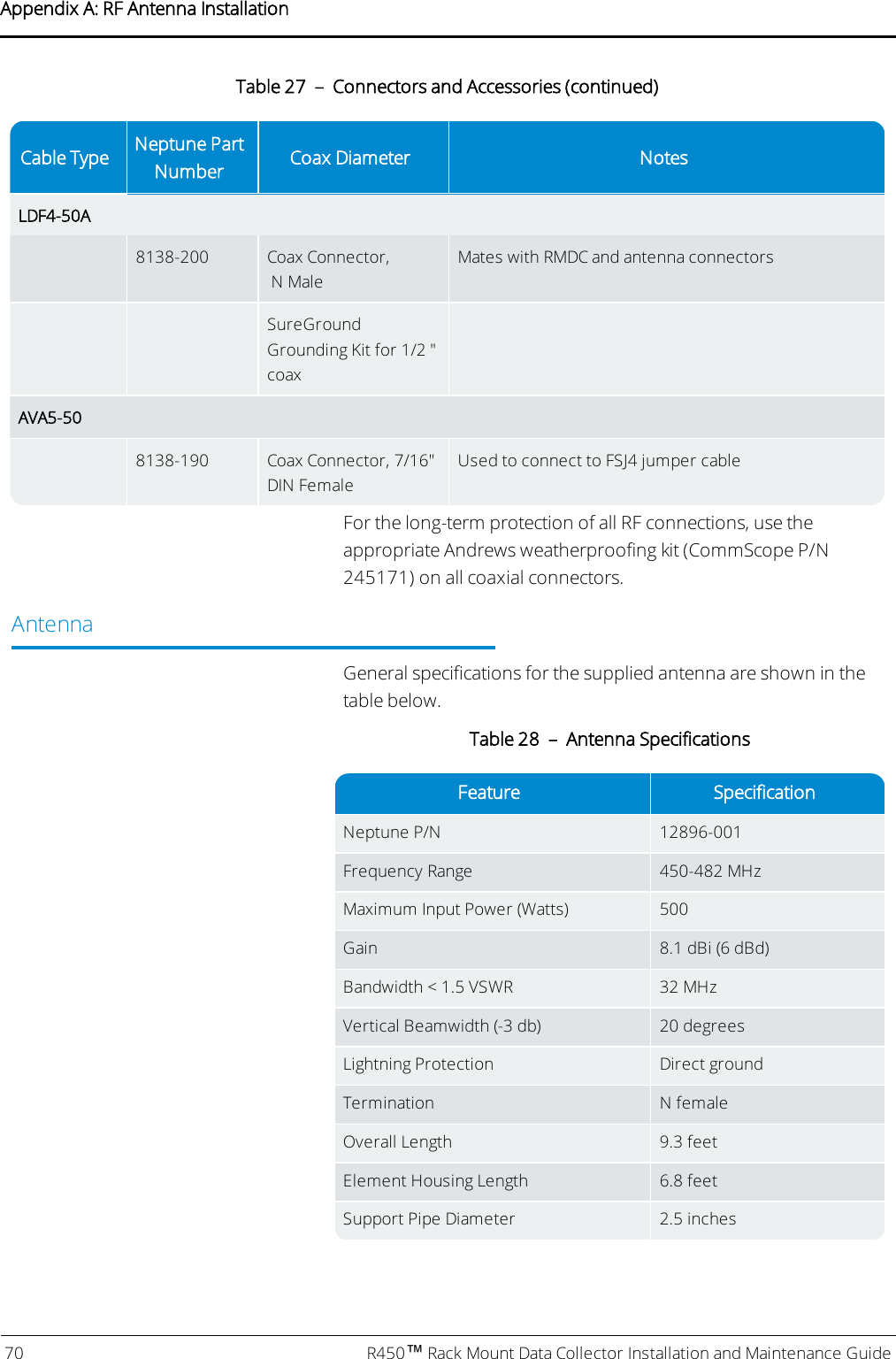
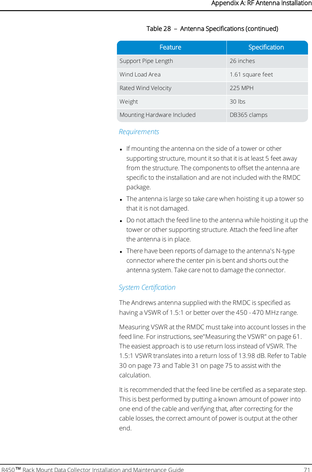
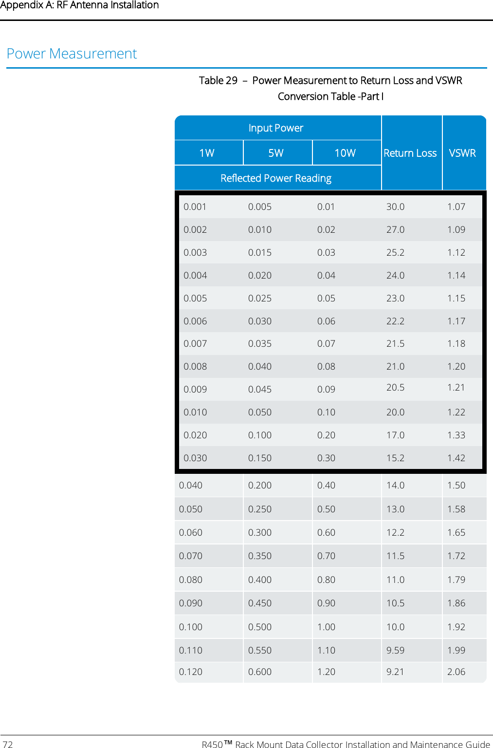
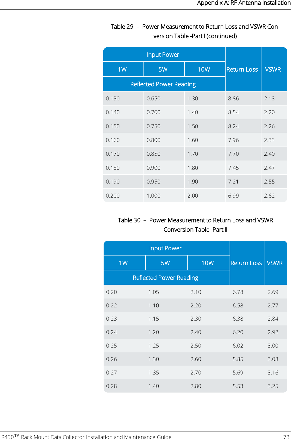
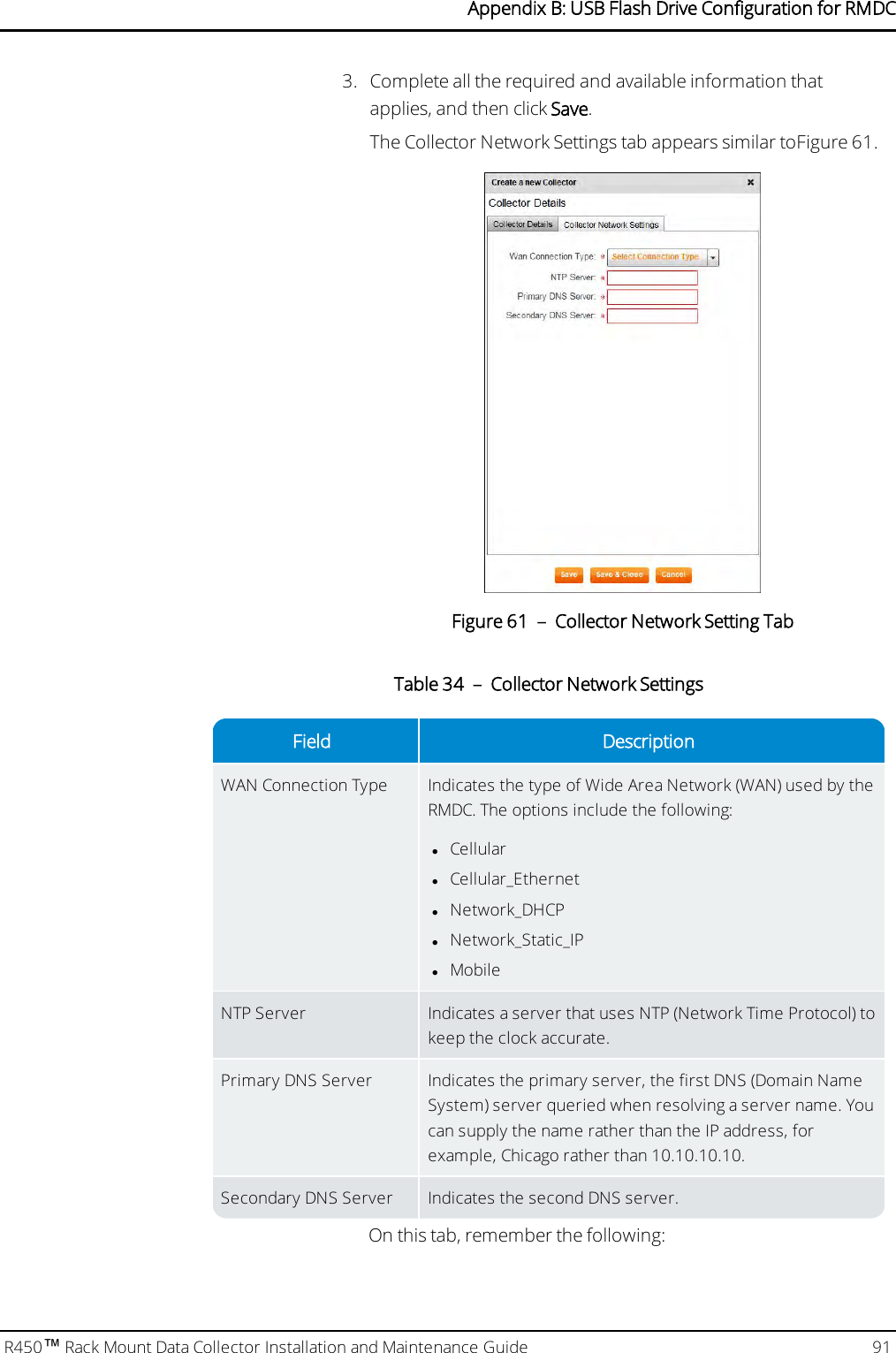
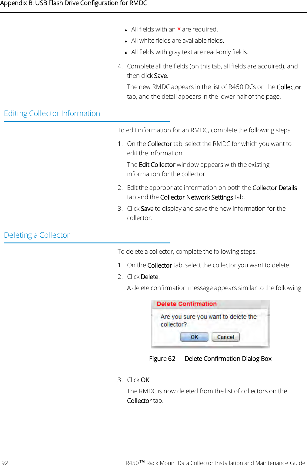
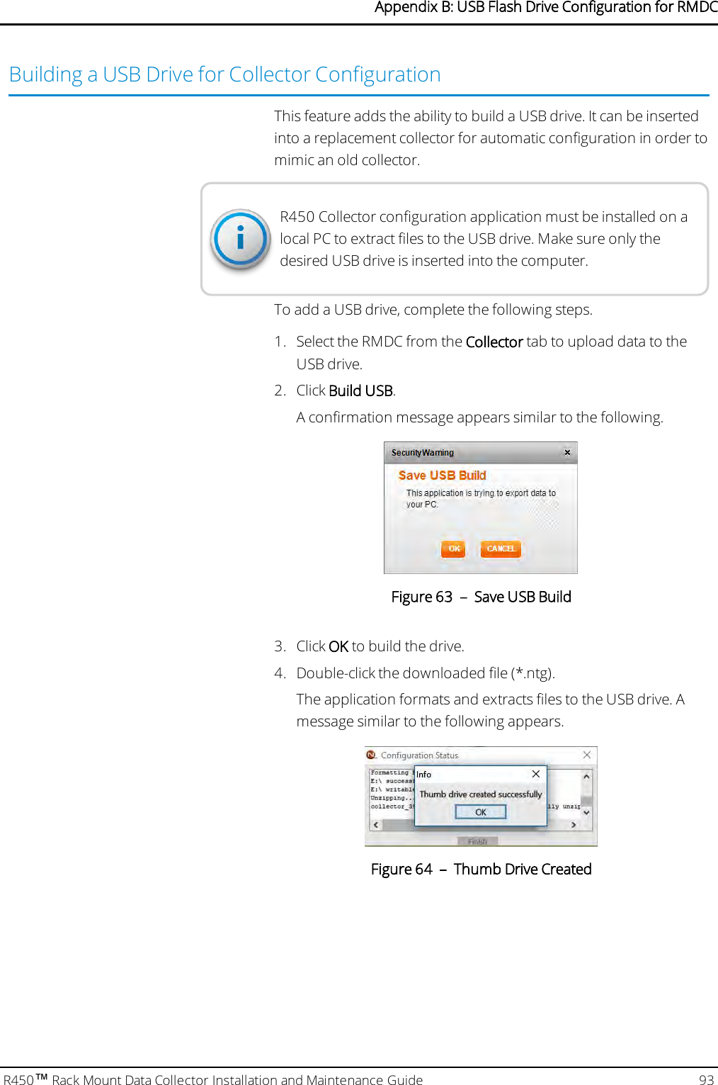
User Manaul Rack Mount DC

R450™ Rack Mount Data CollectorInstallation and Maintenance Guide
CopyrightThis manual is an unpublished work and contains the trade secrets andconfidential information of Neptune Technology Group Inc., which arenot to be divulged to third parties and may not be reproduced ortransmitted in whole or part, in any form or by any means, electronic ormechanical for any purpose, without the express written permission ofNeptune Technology Group Inc. All rights to designs or inventionsdisclosed herein, including the right to manufacture, are reserved toNeptune Technology Group Inc.Neptune engages in ongoing research and development to improveand enhance its products. Therefore, Neptune reserves the right tochange product or system specifications without notice.Trademarks Used in this ManualR450 Rack Mount Data Collector is a trademark of Neptune TechnologyGroup Inc. R450 is a trademark of Neptune Technology Group Inc. N_SIGHT is a registered trademark of Neptune Technology Group Inc.R450 System is a trademark of Neptune Technology Group Inc. Otherbrands or product names are the trademarks or registered trademarksof their respective holders.FCCNoticeThis device complies with Part 15 of the FCC Rules. Operation is subjectto the following two conditions: (1) this device may not cause harmfulinterference, and (2) this device must accept any interference received,including interference that may cause undesired operation.NOTE: This equipment has been tested and found to comply with thelimits for a Class B digital device, pursuant to Part 15 of the FCC Rules.These limits are designed to provide reasonable protection againstharmful interference in a residential installation. This equipmentgenerates, uses, and can radiate radio frequency energy, and if notinstalled and used in accordance with the instructions, may causeharmful interference to radio communications. However, there is noguarantee that interference will not occur in a particular installation.
If this equipment does cause harmful interference to radio or televisionreception, which can be determined by turning the equipment off andon, the user is encouraged to try to correct the interference by one ormore of the following measures:lReorient or relocate the receiving antenna.lIncrease the separation between the equipment and receiver.lConnect the equipment into an outlet on a circuit different from thatto which the receiver is connected.lConsult the dealer or an experienced radio / TV technician for help.RF Exposure InformationThis equipment complies with the FCC RF radiation requirements foruncontrolled environments. To maintain compliance with theserequirements, the antenna and any radiating elements should beinstalled to ensure that a minimum separation distance of 100 cm ismaintained from the general population.CAUTION: Changes or modifications not expressly approved byNeptune Technology Group could void the user's authority tooperate the equipment.Industry CanadaThis Class B digital apparatus meets all requirements of the CanadianInterference Causing Equipment Regulations. Operation is subject tothe following two conditions: (1) this device may not cause harmfulinterference, and (2) this device must accept any interference received,including interference that may cause undesired operation.Cet appareillage numérique de la classe B répond à toutes lesexigences de l'interférence canadienne causant des règlementsd'équipement. L'opération est sujette aux deux conditions suivantes:(1) ce dispositif peut ne pas causer l'interférence nocive, et (2) cedispositif doit accepter n'importe quelle interférence reçue, y comprisl'interférence qui peut causer l'opération peu désirée.
Professional InstallationIn accordance with Section 15.203 of the FCC rules and regulations, theR450 Rack Mount Data Collector must be professionally installed.Changes or modifications not expressly approved by the partyresponsible for compliance could void the user's authority to operatethe equipment.Important Safety PrecautionsReview the following precautionary measures prior to installation.CAUTION: Refer installation and service to qualified service personnelonly.lReview the following precautionary measures prior to installation.Connections to the AC mains must be performed by a licensedelectrician. No user-installable parts inside.lInstallation must be done in accordance with the instructionscontained in this manual.lInstallation must be done in accordance with the National ElectricalCode (NEC), NFPA 70 or Canadian Electrical Code (CEC), CSA C22.2,No. 1.lIn particular, installation must be done in accordance with NECArticle 810 or CEC Section 54.lThis unit is not intended to be powered directly from the MainDistribution System.WARNING: Risk of explosion if UPS battery is replaced by an incorrecttype. Dispose of used batteries according to the manufacturer'sinstructions.
Installations that Require DiggingIf the installation requires digging, review the following warning.WARNING: If the installation site requires digging, survey the area forconcealed hazards. Call 811, the Call Before You Dig phone center,before proceeding. Be sure to locate any electric, natural gas, andwater lines as well as cable and phone lines. In some states andjurisdictions, it is the law. Most state laws require at least two to threefull work day's notice.Antenna AlertIf installing or removing an antenna, review the following warnings.WARNING: Antenna contact with high voltage wires can result indeath. Watch for overhead electric power lines when erecting theantenna and mast. For proper installation and grounding of theantenna, please refer to National Electrical Code (NEC) Article 810and Canadian Electrical Code (CEC) Section 54.WARNING: Do not mount antennas on utility poles, electric servicemasts, or other structures carrying electric light or power wires.Outdoor antennas and coaxial cables must maintain clearance of atleast 2 feet (0.6 m) from power or light wires carrying 250V or less, orat least 10 feet (3.0 m) from power wires carrying more than 250Vper NEC Article 810 and CEC Section 54.
R450™ Rack Mount Data CollectorInstallation and Maintenance GuideLiterature No. IMR450 RMDC 08.18Part No. 12835-002Neptune Technology Group Inc.1600 Alabama Highway 229Tallassee, AL 36078Tel: (800) 633-8754Fax: (334) 283-7293Copyright © 2003 - 2018Neptune Technology Group Inc.All Rights Reserved
ContentsChapter 1: Product Description 1General Product Overview 1Before you Begin 2Two Versions of RMDC Installation 2Determining How to Install the RMDC 3Mounting Components 3Wall Mount 3Poleor H-Frame Installation 4Optimizing System Performance 5Optimizing the Performance of a New System 5Proper Operation 5Maintaining the Performance of the R450 System 7RMDC Components 7Cellular Modem 7Ethernet 9Chapter 2: General Installation Guidelines 11RMDC Specifications 11Electrical Specifications 11Environmental Conditions 11Mechanical Specifications 11RMDCFootprint 11Storage 12Unpacking 12RMDC Installation Kits 12Tools and Materials 13R450 MIU and Magnet 14Chapter 3: Installing theR450™RMDC 15Mounting the RMDC to a Pole or H-Frame 15Locating the Site 15R450™Rack Mount Data Collector Installation and Maintenance Guide vii
Mounting Recommendations 15Mounting Hardware Recommendations 16Attaching Cables for the RMDC 17Attaching the RF 450 MHz Antenna Cable 17Connecting the Ground Wire 18Mounting the Cellular Antenna 19Attaching the Power Plug to the RMDC 21Weatherizing the Cable Connections 21Installing a Wall Mount System 23Mounting the RMDC to a Wall 23Connecting Antenna Cables to the RMDC 25Mounting the Cellular Antenna 25Mounting Hardware 26Connecting the Ethernet Cable 26Connecting the Cables to the RMDC 28Activating the RMDC 29Configuring the Cellular Modem 29Selecting the Carrier 30CDMA Settings (Provisioning) Verizon subscribers: 31GSM Settings (SIMCard Acceptance): 31Configuration Complete 31Configuring the Collector with the USB Flash Drive 32Completing the Installation 33Testing the Connections 33Field Service Tool 34Swiping the MIU 34If You Do Not Receive an Email 35Securing the RMDC 36viii R450™Rack Mount Data Collector Installation and Maintenance GuideContents
R450™Rack Mount Data Collector Installation and Maintenance Guide ixChapter 4: Uninterruptible Power Supply 37UPSSpecifications 38Input 38Output 38Battery 39Physical 39Safety 39Environmental 39Checklists 40UPSSafety Checklists 40Battery Safety Checklist 41Site Preparation Warnings 42Grounding 42Branch Circuit Breaker Protection 43Disconnects 43Mounting the UPS 43Wall Mounting 44Pole Mounting 44Connecting the UPS 45Tools and Materials Required 45Procedure 46Wiring the Input and Output Connectors 46Installing and Wiring the UPS 46Powering On the UPS 47Servicing the UPS 47Checking UPS Status LEDs 47Checkup Complete 49Chapter 5: Troubleshooting 51Equipment Required 51PC Notebook Configuration 52Potential RMDCProblems 52Contents
Multiple RMDC Not Syncing with Host Database 52Storm Damage Affecting Multiple Sites 52First Steps 52Initial Site Activities 53Checking the General Health of Each Module 53CPU Board Power and Activity Visual Check 53Radio Power Visual Check 55Checking the Backhaul Modem Power and Connectivity 56CalAmp Vanguard Modem Visual Check 56Additional Detail Checks 57Verify Main Power 57Verifying Switched DC Power 58Verifying Cellular Modem Power 59Verifying Connectivity 59CalAmp Vanguard Modem 59Ethernet 60Verifying Radio and NTGModem Functionality Using the MIU 60RMDC is Syncing but Not Supplying MIU Data 61Initial Observations 61Radio Transmits but ALM Indicator Flashes 61Measuring the VSWR 61The Radio Never Transmits 62Reduction in Amount of Data Collected 63Contacting Customer Support 64By Phone 64By Fax 64By Email 64x R450™Rack Mount Data Collector Installation and Maintenance GuideContents
R450™Rack Mount Data Collector Installation and Maintenance Guide xiAppendix A: RF Antenna Installation 65RF Antenna Overview 65Mounting the Antenna 65Mounting the Antenna Mast 66Site Recommendations 66Feed Line and Antenna Recommendations 67Feed Line 67Feed Line Requirements 67Cable Guidelines 68Neptune Part Numbers 69Antenna 70Requirements 71System Certification 71Power Measurement 72Coax Cable Loss 75VSWRCalculation 76Using a Wattmeter and a Handheld 450MHz Radio 77Using the AEA 140-525 Antenna Analyzer 78Taking the Reading and Calculating VSWR 78General Installation Guidelines 79Unpacking 79RF Antenna Installation Kit 79Tools and Materials 80Installing the RF Antenna 81Mounting the RF 450 MHz Antenna 81Mounting the Antenna Mast to the Building 82Attaching the RF 450 MHz Antenna Cable 83Weatherizing the Cable Connections 84Troubleshooting the RF Antenna 84Equipment Required 84Testing the RF Antenna 85Contents
Appendix B: USB Flash Drive Configuration for RMDC 87Overview 87Creating a Collector 87Searching for Collectors 87Creating a New Collector 89Editing Collector Information 92Deleting a Collector 92Building a USB Drive for Collector Configuration 93Appendix C: Ethernet Termination 95RJ-45 Straight-Through Ethernet Cable 95RJ-45 Crossover Ethernet Cable 95Determining if You Need a Crossover Cable 96Appendix D: Cellular Antenna Coax Cable 97Cellular Antenna Coax Cable Recommendations 97Appendix E: Strut Clamp Recommendations 99Glossary 101Index 107xii R450™Rack Mount Data Collector Installation and Maintenance GuideContents
FiguresFigure 1 – R450™ Rack Mount Data Collector 1Figure 2 – Wall-Mount Installation 3Figure 3 – Pole Installation 4Figure 4 – R450 Rack Mount Data Collector 12Figure 5 – RF 450 MHz Antenna 12Figure 6 – R450 Rack Mount Data Collector 15Figure 7 – RF 450 MHz Antenna Connection 17Figure 8 – Antenna Connections 17Figure 9 – Ground Wire 18Figure 10 – Items for Cellular Antenna 19Figure 11 – Attaching the Cellular Antenna 19Figure 12 – Tighten Bolt for Cellular Antenna 20Figure 13 – Cable to Cellular Antenna 20Figure 14 – Cellular Antenna Connection at Base 20Figure 15 – Weatherizing Connections 21Figure 16 – Weatherizing the BaseConnection 22Figure 17 – Weatherizing the AntennaConnection 22Figure 18 – RMDC Mounted on Wall 24Figure 19 – Adding Cables to the RMDC 25Figure 20 – Ethernet Port Connection 26Figure 21 – Feed-Through Assembly 27Figure 22 – RJ45 Ethernet Plug 27Figure 23 – Ethernet Plug Terminated 27Figure 24 – Ethernet Plug Receptacle 27Figure 25 – Connecting the RMDC 28Figure 26 – Main Breaker Switch 29Figure 27 – Modem in R450 RMDC 29Figure 28 – Vanguard Modem Back Panel 30R450™Rack Mount Data Collector Installation and Maintenance Guide xiii
Figure 29 – USB Port on CPU Board 32Figure 30 – Collector's Internal Power Supply LEDs 32Figure 31 – Activating the MIU 34Figure 32 – Email Sent from RMDC 35Figure 33 – Radio TXLight 35Figure 34 – Unit Door Locks 36Figure 35 – Outdoor UPS (Closed) 37Figure 36 – Outdoor UPS (Cover Removed) 37Figure 37 – Strut Channel or Wall Mounting 44Figure 38 – Pole Mounting Straps 44Figure 39 – Wire Input and Output Connectors 46Figure 40 – RMDC Power Plug 47Figure 41 – LEDs Above CPU 54Figure 42 – Ethernet Status LEDs 55Figure 43 – Radio LEDs 55Figure 44 – Modem Indicator LEDs 56Figure 45 – Radio Modem Power Front Panel Connector 57Figure 46 – RMDC Power Supply 58Figure 47 – Radio Modem Power Front Panel Connector 58Figure 48 – Vanguard Modem Power Connector 59Figure 49 – CalAmp Vanguard Modem with RSSI LED 59Figure 50 – NTG Modem Status LEDs 60Figure 51 – Standoff Mounting Bracket 80Figure 52 – RF 450 MHz Antenna 80Figure 53 – RF 450 MHz Antenna to be Mounted 82Figure 54 – Securing the Pole Bracket 82Figure 55 – Lining Up Second Bracket 83Figure 56 – RF 450 MHz Antenna Connection 83Figure 57 – Weatherizing the RF Antenna Connection 84xiv R450™Rack Mount Data Collector Installation and Maintenance GuideFigures
R450™Rack Mount Data Collector Installation and Maintenance Guide xvFigure 58 – Collector Search 87Figure 59 – Collector Search Results 88Figure 60 – Create a New Collector Window 89Figure 61 – Collector Network Setting Tab 91Figure 62 – Delete Confirmation Dialog Box 92Figure 63 – Save USB Build 93Figure 64 – Thumb Drive Created 93Figure 65 – Straight-Through Ethernet Cable 95Figure 66 – RJ-45 Crossover Ethernet Cable 95Figures
This page intentionally left blank.xvi R450™Rack Mount Data Collector Installation and Maintenance GuideFigures
TablesTable 1 – R450™ RMDC Cellular Modem Components List (P/N 12799-800) 8Table 2 – R450™ RMDC Ethernet Components List 9Table 3 – Electrical Specifications 11Table 4 – Environmental Conditions 11Table 5 – Recommended Tools and Materials 13Table 6 – R450 RMDC Pole Mounting Hardware Recommendations 16Table 7 – Installing a Wall Mount System 23Table 8 – R450 RMDC Wall Mounting Hardware Recommendations 24Table 9 – Lights on the CPU Board 33Table 10 – Radio Tx Light - Identify Problem 35Table 11 – UPS Specifications 38Table 12 – Input Specifications 38Table 13 – Output Specifications 38Table 14 – Battery Specifications 39Table 15 – Physical Specifications 39Table 16 – Safety Specifications 39Table 17 – Environmental Specifications 39Table 18 – UPS Safety Checklist 40Table 19 – Battery Safety Checklist 41Table 20 – RMDC Does not Power Up 48Table 21 – UPS Status LEDs 48Table 22 – Verify UPS is Producing Correct Voltage 49Table 23 – Visual Check Modem RSSI and SVC LEDs 56Table 24 – Modem Status LEDs 57Table 25 – Material Needed for Cable Installation 68Table 26 – Neptune Part Numbers for Cable 69Table 27 – Connectors and Accessories 69Table 28 – Antenna Specifications 70R450™Rack Mount Data Collector Installation and Maintenance Guide xvii
Table 29 – Power Measurement to Return Loss and VSWR Conversion Table -Part I 72Table 30 – Power Measurement to Return Loss and VSWR Conversion Table -Part II 73Table 31 – Coax Cable Loss Table 75Table 32 – Recommended Tools and Materials 80Table 33 – Collector Details 90Table 34 – Collector Network Settings 91Table 35 – Cable Color Code Table 96Table 36 – Coax Cable Recommendations for Cellular Antenna 97Table 37 – Recommended Stainless Steel Strut Clamps 99xviii R450™Rack Mount Data Collector Installation and Maintenance GuideTables
R450™Rack Mount Data Collector Installation and Maintenance Guide 1Chapter 1: Product DescriptionThis chapter introduces the installation process. It explains the focus of the guide,the pre-installation personnel responsibilities, and general information on technicalsupport.General Product OverviewThis section provides a general description of the R450™ Rack Mount DataCollector (RMDC).The RMDC receives, stores, and communicates meter reading data to the Neptunehost software. The RMDC collects meter reading data from Neptune’s R450™ MeterInterface Unit (MIU) interfacing with Neptune’s absolute encoder register. This datacan be uploaded to the Customer Information System (CIS) and sent to the utilitybilling system for processing.Figure 1 – R450™ Rack Mount Data CollectorThe RMDC operates in frequencies in the 450-470 MHzlicensed band. A Federal Communications Commission (FCC)license is required prior to installation of the system.
Before you BeginBefore you install the RMDC, it is important to become familiar withthe unit and its components. This guide is intended for installerand is designed to help in the installation process. It containsinformation on the components and specifications, the siteselection, and the actual installation of the unit.WARNING: If the installation site requires digging, survey thearea for concealed hazards. Call 811, the Call Before You Digphone center, before proceeding. Be sure to locate any electric,natural gas, and water lines as well as cable and phone lines. Insome states and jurisdictions, it is the law. Most state lawsrequire at least two to three full work day's notice. Install inaccordance with the FCC site license.Two Versions of RMDC InstallationThere are two RMDC versions available depending on the utility'sbackhaul preference. Each type is powered by external 12V DCpower. Power is supplied to the RMDC by an UninterruptiblePower Supply (UPS).Neptune provides an installation kit for each type of installation.The standard configuration of the RMDC backhaul is a cellularmodem. The other backhaul option available is an Ethernetconnection.Backhaul TypelCellular modem (P/N 12799-800)lEthernet (P/N 12799-810)The RMDC can be mounted on a wall, a pole, or H-frame.2 R450™Rack Mount Data Collector Installation and Maintenance GuideChapter 1: Product Description
Determining How to Install the RMDCConsider the following information.WARNING: Do not mount the RMDC, antenna mast, antenna, orlead-in conductor to a pole or similar structure carrying openelectric light, power wires, or trolley wires over 250 volts. SeeNEC, Article 810.Depending upon the availability of communications, you canuse a cellular modem or Ethernet backhaul. Use with theselection checklist before installing the RMDC.Mounting ComponentsThis section describes the various mounting components for theRMDC.Wall MountA wall-mounted RMDC can be installed indoors; however, becausethe unit uses an external antenna, you need an antenna mast.Refer to Figure 2 for how to mount the RMDC to a wall.Figure 2 – Wall-Mount InstallationR450™Rack Mount Data Collector Installation and Maintenance Guide 3Chapter 1: Product Description
Depending upon the availability of communications, you canuse a cellular modem or Ethernet backhaul.Poleor H-Frame InstallationUse the pole or H-Frame installation to mount the R450 RMDC onan outdoor free-standing pole or H-frame. Refer to Figure 3 forhow to install the RMDC on a pole.Figure 3 – Pole InstallationDepending upon the availability of communications, you canuse a cellular modem or Ethernet backhaul.4 R450™Rack Mount Data Collector Installation and Maintenance GuideChapter 1: Product Description
Optimizing System PerformanceThis section addresses situations where the system is functioning,but the R450 RMDC or MIU communication is not performing asexpected.This discussion covers two situations:lNewly-installed system does not perform per specification.lInstalled system performance degrades suddenly or over time.Optimizing the Performance of a New SystemBefore you install the system, Neptune uses computer softwareand other resources to predict the performance of the system.Each site survey recommends a minimum number of RMDCs toprovide the desired performance over a specified coverage area.The survey also recommends antenna placement and looks forpotential radio interference. Neptune provides a propagationmodel which uses sophisticated software to predict the systemperformance. If you place an RMDC outside the recommendedlocations, it might not perform well.CAUTION: If Neptune's propagation model is not followed,inadequate performance can occur.Proper OperationReview the following note.Owners of both licensed and unlicensed equipment areresponsible for the proper operation of their equipment. If it isnot operating within specifications, the owner is required tobring the system into compliance or stop using it. Thecollaborative effort of all the affected parties is required to solvethis problem.It is possible for a piece of equipment to be functioning totallywithin its required specifications and still cause interference withthe R450™ System.R450™Rack Mount Data Collector Installation and Maintenance Guide 5Chapter 1: Product Description
During the initial installation, Neptune advises using a receiver orhigh-quality spectrum analyzer connected to the antenna to assurethe transmit and receive frequencies are free from interference.Additionally, be sure that there are no potentially interfering signalsaround the frequencies the RMDC uses for transmitting andreceiving. The overall noise level can potentially reduce thesensitivity of the RMDC or MIU receivers. A Rohde & SchwarzFSH3.03 or FSH3.23 or equivalent spectrum analyzer isacceptable.Problems can occur from a number of sources. Some commonproblems include:lImproper installation resulting in loose connectors. Refer to "RFAntenna Installation" on page65 of Appendix A to confirm thecorrect installation procedures.CAUTION: You must provide Appendix A to antenna contractorsprior to installation. Failure to follow the procedures in theAppendix can result in poor system performance.lLocal cable systems operating with RF leakage from cables andamplifiers can degrade the performance of the R450 System.lLocal businesses and factories can have equipment that raisesthe ambient noise level, reducing the ability of the RMDC to hearMIUs.lLocal residences and businesses can have equipment thatinterferes with the R450 System.Site surveys often find these problems but cannot detectintermittent, factory shift-related, or other time-specific sources ofinterference.Being in close proximity to a high-power commercial broadcastantenna produces a unique set of problems. Loose or badlycorroded hardware on or near the site can cause signals from theRMDC or other transmitters near the site to combine with thebroadcast signal and produce interfering signals. Incorrectlyinstalled antennas and feed lines can also cause similar problems.The RMDC and other local transmitters themselves can also be asource of re-radiated interference. Additional equipment that yourinstaller recommends can help control these issues.6 R450™Rack Mount Data Collector Installation and Maintenance GuideChapter 1: Product Description
Terrain and the types of buildings in the area can affect theperformance of the R450 System. Hilly or rolling terrain as well astall buildings can make it difficult to receive even local MIU data.Placement of the MIUs (wall mount and pit style) can be critical insome areas. Additional RMDCs that supplement the problem areasis the best solution in these situations.Maintaining the Performance of the R450 SystemFor consistent performance, be sure that you have properlyinstalled all the R450 MIUs so that the R450 System can reliablyreceive their transmissions.The Troubleshooting chapter of this guide includesrecommendations on how to verify that the RMDC and antennasystem are performing up to specification.Storm activity can degrade the performance of the RMDC. If thishappens, check the lightning arrestors and replace them, ifdefective.Running the surveys again using the radio receiver can identify newsources of interference. For problems related to specific timeperiods, run the surveys during those time periods.RMDC ComponentsThe following section describes the components of the RMDC.Cellular ModemThe RMDC is mounted on either a pole, wall, or H-Frame. Table 1on the next page includes the components for the RMDC cellularmodem version.R450™Rack Mount Data Collector Installation and Maintenance Guide 7Chapter 1: Product Description
Part Number Description Qty12799-800 R450 Rack Mount, 4G Cellular Modem includes:lUninterruptible power supply (UPS)l4G/LTE cellular antennal6-foot cellular coax cablelStrut clamplRJ45 connector,lEnclosure keylManual112896-001 Antenna, RF Omni (mounting hardware included) 1Coax cable (see Appendix A, "RF Antenna Installation" on page65) As required13751-001 Antenna, 4G LTE cellular (included with the RMDC) 110046-112 Coax Cable, six-foot, cellular antenna (included with the RMDC) 113750-001 Strut clamp, 3/4-inch, stainless steel (included with RMDC) 113450-200 Uninterruptible Power Supply (UPS)kit (includes UPS, pole/wall mountingbracket, DC power cord, DC cord grip, and stainless steel clamps). Othervendors supply wall mounting hardware.112835-002 RMDC Installation and Maintenance Guide 1Table 1 – R450™ RMDC Cellular Modem Components List (P/N 12799-800)The cellular modem requires a System Information Manager(SIM) card which must be ordered separately. To obtain a SIMcard, contact your preferred cellular service provider and givethem the modem Mobile Equipment Identifier (MEID)andInternational Mobile Equipment Identifier (IMEI) numbers.8 R450™Rack Mount Data Collector Installation and Maintenance GuideChapter 1: Product Description
EthernetTable 2 shows the parts included in the RMDC Ethernet kit.Part Number Description Qty12799-810 R450 Rack Mount, Ethernet version includes:lUninterruptible power supply (UPS)l4G/LTE cellular antennal6-foot cellular coax cablelStrut clamplRJ45 connectorlEnclosure keylManual112896-001 Antenna, RFOmni (mounting hardware included) 1Coaxial cable (see Appendix A, "RF Antenna Installation" on page65 As required13450-200 UPS Kit (includes UPS, pole/wall mounting bracket, DC power cord, DC cordgrip, and stainless steel clamps). Wall mounting hardware to be supplied byothers113138-001 External RJ45 Plug Kit (included with R450 RMDC - Ethernet version) 112835-002 RMDC Installation and Maintenance Guide 1Table 2 – R450™ RMDC Ethernet Components ListR450™Rack Mount Data Collector Installation and Maintenance Guide 9Chapter 1: Product Description
This page intentionally left blank.Chapter 1: Product Description10 R450™Rack Mount Data Collector Installation and Maintenance Guide
R450™Rack Mount Data Collector Installation and Maintenance Guide 11Chapter 2: General Installation GuidelinesThis chapter describes the specifications for the R450™ Rack Mount Data Collector( RMDC). It includes information on storage, unpacking, preliminary tests, tools,materials, site selection, and installation of the RMDC.RMDC SpecificationsThis section provides the specifications of the RMDC.Electrical SpecificationsSpecification DescriptionDCPower 12V DC, 7APower Consumption 84 WattsTable 3 – Electrical SpecificationsEnvironmental ConditionsCondition DescriptionOperating Temperature -22° to 140°F (-30° to 60°C)Storage Temperature -40° to 185°F (-40° to 85°C)Operating Humidity 0 to 95% Non-condensingEnvironmental Rating NEMA 4X enclosure boxOperating Altitude Less than 6561 feet (2000 meters)Table 4 – Environmental ConditionsMechanical SpecificationsThe weight of the RMDC is 100 lbs.RMDCFootprintThe RMDC measures 24"h x 27"w x 23"d.
StorageUpon receipt, inspect shipping containers and their contents for damage prior tostorage.After inspection, store the cartons in a clean, dry environment where thetemperature remains between -40° and 185°F (-40° and 85°C).UnpackingAs with all precision electronic instruments, handle the RMDC withcare; however, no special handling is required.After unpacking the RMDC, inspect it for damage. If any parts of theRMDC appear to be damaged or prove to be defective uponinstallation, notify your Neptune sales representative. If the unit oritem requires reshipment, use the original cardboard box andpacking material.RMDC Installation KitsThe RF 450 MHz antenna and accessories are now orderedseparately from the RMDC. The RF 450 MHz antenna, coaxialcables, and coaxial connectors must be ordered as accessories.See "RF Antenna Installation" in Appendix A for a list of the antennaaccessories and cables.Figure 4 – R450 Rack Mount Data Collector Figure 5 – RF 450 MHz Antenna12 R450™Rack Mount Data Collector Installation and Maintenance GuideChapter 2: General Installation Guidelines
Tools and MaterialsTable 5 below shows the recommended tools and materials youneed to successfully install the RMDC.Some items do not apply to your specific installation, and the listdoes not contain all tools or materials depending on whichinstallation method you use.Item Description/Recommendation UseTool Kit Contains standard tools including:lAssorted screwdrivers (medium, Flat-Head (slotted), Phillips head)lCordless electric drill/assorted bitslAdjustable wrenchlStandard socket wrench setlStandard box-end wrench setlHammerlChannel locksVarious installation proceduresperformed by the installer.UV-Stable Ties 8" and 12" (20.32 cm and 30.48 cm) Securing smaller short coaxial.Cable Hangers Various sizes Securing coaxial cable. For largercoaxial (1/2" diameter and larger),secure to tower or structure permanufacturers recommendations.RMDC Key Key for lock on unit Securing the unit.Weatherizing Kit 3M Scotch®Wireless Kit P/N: WK-101 orTimes Microwave P/N: WK-S-2Weatherproofing coaxial cableconnections.Coaxial Grounding Kit SG12-06B2A for 1/2" LDF4-50 Coaxial orSG78-06B2A for 7/8" AVA5-50 CoaxGrounding coaxial cable (seeAndrew Bulletin 17800B-JC).Coaxial HoistingGripsAs recommended by coaxial cablemanufacturer (see Andrew Bulletin17800B-JC)For tower and monopoleinstallations - hoist and securecoaxialPersonal ProtectiveEquipment (PPE)Wear OSHA approved PPE as required.Safety glasses must meet ANSI Z87.1Table 5 – Recommended Tools and MaterialsR450™Rack Mount Data Collector Installation and Maintenance Guide 13Chapter 2: General Installation Guidelines
R450 MIU and MagnetIf you have R450 MIUs already installed, you can use these to test ifthe RMDC is receiving readings. However, it is recommended thatyou take an R450 MIU and Neptune magnet with you when youinstall the RMDC. These items are needed to test the unit. See"Swiping the MIU" on page34.When you install the R450 MIU, be sure that the N_SIGHT PLUShost software is running and that you have an R450 MIU andmagnet with you. Use the R450 MIU and magnet to test theunit.14 R450™Rack Mount Data Collector Installation and Maintenance GuideChapter 2: General Installation Guidelines
R450™Rack Mount Data Collector Installation and Maintenance Guide 15Chapter 3: Installing theR450™RMDCThis chapter details the installation instructions for the R450™ Rack Mount DataCollector (RMDC). There are two installation options:l"Mounting the RMDC to a Pole or H-Frame" belowl"Installing theR450™RMDC " aboveMounting the RMDC to a Pole or H-FrameThis section provides information on mounting the RMDC to a pole orH-frame.Locating the SiteChoose a location that does not interfere with any other wiring and is easilyaccessible. After selecting a site, complete the following procedures.Mounting RecommendationsWARNING: Outdoor antennas and coaxial cables should maintain a clearance ofat least 2 feet (0.6 m) from open electric light or power service conductors of 250volts or less. If the power wires are more than 250V, maintain a clearance of atleast 10 feet (3.0 m) per NEC Article 810 and CEC Section 54.You can mount the RMDC to a pole (4 inch or larger) using two 3/4-inch widestainless steel straps (Band-It #C20699 strap, #C25699 buckle, and #C00169standard tool). Other vendors supply the straps, buckles, and standard tools.Hardware needs to be corrosion resistant and coastal areas can use stainless steel.Figure 6 – R450 Rack Mount Data Collector
Mounting Hardware RecommendationsTable 6 lists installation types and the recommended mountinghardware to use.Installation Type Comments Recommended Mounting Hardware(supplied by other vendors)Small Pole 2-inch to 4-inch diameter galvanizedsteel, Schedule 40lSlotted or half slot steel strut channel (1-5/8" x 1-5/8" x 22" L), two mounted to the back of the R450RMDC enclosurel3/8"-16 x 1" Grade 8 (A490) bolts, four minimum1l3/8"-16 nutsl3/8" fender washerslTwo steel strut clamps (2" to 4" depending on polesize)lOptional: 1/4"-20 x 1" Grade 8 (A490) bolts; use aminimum of eight; also, 1/4"-20 nuts and 1/4"fender washersLarge Pole 4-inch diameter or larger Use two 3/4" wide stainless-steel straps (Band-It#C20699 strap, #C25699 buckle, and #C00169standard tool)2-Pole"H-Frame" StrutChannelRecommended minimum pole size is2-inch diameter galvanized steel,Schedule 403/8"-16 x 1" bolts, 3/8"-16 spring nuts, and 3/8"washers; use a minimum of four 3/8" boltsOptional: 1/4"-20 x 1" Grade 8 (A490) bolts and 1/4"washers; use a minimum of eight1Note: If mounting to the shallower 13/16" depth strut channel (1-5/8" x 13/16"), then 7/8" long bolts are recommended to keep frombottoming out.2Note: Hardware listed is the minimum allowable recommended hardware. Additional provisions can be necessary for high wind areas.Table 6 – R450 RMDC Pole Mounting Hardware RecommendationsFor pipe mounting, use Schedule 40 or Schedule 80 galvanizedsteel pipe with at least a 2-inch or larger diameter. Seat the pipeper local codes.16 R450™Rack Mount Data Collector Installation and Maintenance GuideChapter 3: Installing theR450™RMDC
For general recommendations on strut clamps and sizinginformation, see Appendix E: " Strut Clamp Recommendations"on page99.Attaching Cables for the RMDCThe corresponding sections detail how to attach the followingcomponents:lRF 450 MHz antenna cablelGround wirelCellular antennalAC Power plugFigure 7 – RF 450 MHz Antenna ConnectionAttaching the RF 450 MHz Antenna CableTo attach the RF 450 MHz antenna cable, complete the followingsteps.1. Locate the RF 450 MHz antenna cable that extends from theRF 450 MHz antenna cable conduit.2. Connect the RF 450 MHz antenna cable to the RF 450 MHzantenna connector located on the bottom of the RMDC. SeeFigure 83. Tighten the coaxial connector to 15 - 20 in-lb (1.7 - 2.2 Nm)for N-type connector.Figure 8 – Antenna ConnectionsR450™Rack Mount Data Collector Installation and Maintenance Guide 17Chapter 3: Installing theR450™RMDC
WARNING: Give special consideration when the RMDC youinstalled is inside a building.Connect the outer conductor (shield) of the coaxial cable to theearth (grounded) at the entrance to the building using theappropriate coax grounding kit. Be sure this is done inaccordance with applicable national electrical installation codes(Section 820.93 of the National Electrical Code (NEC),ANSI/NFPA 70).Connecting the Ground WireTo attach the ground wire, complete the following steps.1. Locate the lightning protection system ground for the site.2. Connect the external ground lug of the RMDC to the lightningprotection system ground for that site, as illustrated in Figure9. Use #6 American Wire Gauge (AWG) copper wire with aminimum temperature rating of 75°C.3. Tighten with a flathead screwdriver. Torque to 35 in-lb. (4.0Nm).Figure 9 – Ground WireIf you are using an Ethernet backhaul, see"Connecting theEthernet Cable" on page26.18 R450™Rack Mount Data Collector Installation and Maintenance GuideChapter 3: Installing theR450™RMDC
Mounting the Cellular AntennaNeptune recommends mounting the cellular antenna to thetower or mast. Make sure the tower (or mast) does not obscurethe line of sight path to the nearest cellular carrier's tower.If the cellular modem RSSI signal level is marginal or weak,relocate the cellular antenna to the opposite side of the tower(or mast).To mount the cellular antenna, complete the following steps.1. Locate the cellular antenna, and strut clamp. See Figure 10.Figure 10 – Items for Cellular AntennaSome installations require a longer coax cable for the cellularantenna connection. See "Appendix D: Cellular Antenna CoaxCable" for recommendations.2. Using the 3/4-inch strut clamp, attach the cellular antenna toone side of the top strut channel connected to the back of theRMDC, as illustrated in Figure 11.Figure 11 – Attaching the Cellular AntennaR450™Rack Mount Data Collector Installation and Maintenance Guide 19Chapter 3: Installing theR450™RMDC
WARNING: Secure the clamp around the silver band of thecellular antenna only. Damage can occur if the clamp is securedaround any other part of the antenna.3. Using a 3/8-inch socket wrench, tighten the bolt for the strutclamp around the cellular antenna, as illustrated in Figure 12.Figure 12 – Tighten Bolt for Cellular Antenna4. Connect the cable to the cellular antenna before connecting itto the base of the RMDC. See Figure 13.5. Tighten the coaxial cable connection to 14 in-lb.(1.58 Nm).Figure 13 – Cable to Cellular Antenna6. Connect the cellular antenna cable to the base of theRMDC. See Figure 14.7. Tighten to 14 in-lb. (1.58 Nm).Figure 14 – Cellular Antenna Connection at Base20 R450™Rack Mount Data Collector Installation and Maintenance GuideChapter 3: Installing theR450™RMDC
WARNING: Give special consideration when theRMDC is installed inside a building.The screen (shield) of the coaxial cable must be connected toearth (grounded) at the entrance to the building. Do this inaccordance with applicable national electrical installation codes(Section 820.93 of the NEC, ANSI/NFPA 70).Attaching the Power Plug to the RMDCAttach the circular power plug to the bottom of the RMDC. Pushthe connector plug upward while rotating the outer sleeveclockwise until you feel engagement.Weatherizing the Cable ConnectionsComplete the following instructions to weatherproof the cablesusing the 3M Scotch®Wireless WK-101 or an equivalentweatherproofing kit.1. Using the weatherizing kit, start the tape at the bottom of thecellular antenna connection as illustrated in Figure 15.2. Wrap the tape around the connection several times; slowlywork your way up to weatherize your connection at the base.3. Wrap the 3M Butyl Mastic Tape 2212 according to thedetailed installation instructions in the3M Scotch®Wireless Weatherproofing kit.Figure 15 – Weatherizing Connections4. Wrap the entire section of cable with one or two layers of half-lapped 2-inch (51 mm) wide Scotch®Super 33+™ VinylElectrical Tape according to the detailed installation instructionsin the 3M Scotch®Wireless Weatherproofing kit.R450™Rack Mount Data Collector Installation and Maintenance Guide 21Chapter 3: Installing theR450™RMDC
5. Repeat steps 1 and 2 to weatherize the cellular connection atthe base of the RMDC, as illustrated in Figure 16.Figure 16 – Weatherizing the BaseConnectionFor detailed installation instructions on the 3M Scotch®Wireless Weatherproofing Kit (P/N: WK-101) refer to:http://multimedia.3m.com/mws/media/659028O/scotch-wireless-weatherproofing-kit-wk-101.pdf.6. Repeat steps 1 through 4 to weatherize the RF 450 MHzAntenna feed-in connection at the base of the RMDC, asillustrated in Figure 17.Figure 17 – Weatherizing the AntennaConnectionCAUTION: Wiring the AC-power for the UPS must be done by alicensed electrician. Install the wiring in accordance with the NEC,Canadian Electrical Code (CEC), and local electrical codes.22 R450™Rack Mount Data Collector Installation and Maintenance GuideChapter 3: Installing theR450™RMDC
Installing a Wall Mount SystemThe following section contains the instructions needed to install awall mount system.Complete Instructions Cellular Ethernet1 "Installing theR450™RMDC " on page152 "Installing theR450™RMDC " on page153 "Mounting the Cellular Antenna" onpage194 "Connecting the Ethernet Cable" onpage265 "Installing theR450™RMDC " on page15Table 7 – Installing a Wall Mount SystemMounting the RMDC to a WallChoose a location that does not interfere with any other wiringand is easily accessible.Mounting hardware (screws, bolts, slotted or half-slot steel strutchannels, spring nuts, and strut clamps) for wall or strut channelinstallations, are provided by the party responsible for theinstallation. Hardware needs to be corrosion resistant and coastalareas can use stainless steel.To mount the RMDC to a wall as illustrated in Figure 18 on page24, use the following mounting hardware recommendationsshown in Table 8 on the next page.R450™Rack Mount Data Collector Installation and Maintenance Guide 23Chapter 3: Installing theR450™RMDC
Figure 18 – RMDC Mounted on WallThe mounting hardware listed in Table 8 is supplied by othervendors and should be corrosion resistant. Coastal areas canuse stainless steel.Installation Type Comments Recommended Mounting Hardware(supplied by installation vendors)Wall - strutchannelMounting the RMDC to the strut channel thatis mounted to the wallUse the following:lTwo pieces of slotted or half-slot steelstrut channel (1-5/8" x 1-5/8" x 22" L)l3/8"-16 x 1" Grade 8 (A490) boltsl3/8"-16 spring nutsl3/8" washerslUse minimum of four 3/8" bolts.Optional:l1/4"-20 x 1" Grade 8 (A490) boltsl1/4" washers; use a minimum of eightTable 8 – R450 RMDC Wall Mounting Hardware Recommendations24 R450™Rack Mount Data Collector Installation and Maintenance GuideChapter 3: Installing theR450™RMDC
Installation Type Comments Recommended Mounting Hardware(supplied by installation vendors)Wall - direct Mounting RMDC directly to wall Use the following:l1/4" x 1-3/4" wood screws orl1/4" x 1-3/4" masonry screws(forexample Tapcon HW4-134)lUse a minimum of eight screwsTable 8 – R450 RMDC Wall Mounting Hardware Recommendations (continued)Connecting Antenna Cables to the RMDCThe RF 450 MHz antenna and the communications antennaconnect on the outside of the building to the RMDC inside thebuilding.1. Locate an area behind the wall where the cables can threadthrough to the outside of the building.2. Secure the cables to the bottom of the RMDC as illustrated inFigure 19.3. Thread the cables through to the RMDC antenna and mast.4. Continue to work with the cables on the outside of thebuilding.Figure 19 – Adding Cables to the RMDCMounting the Cellular AntennaSee "Mounting the Cellular Antenna" on page19If you are using an Ethernet backhaul, refer to "Connecting theEthernet Cable" on the next page.R450™Rack Mount Data Collector Installation and Maintenance Guide 25Chapter 3: Installing theR450™RMDC
Mounting HardwareWhen mounting hardware, consider the following.Mount the antenna using a unistrut for the collector or onseparate mounting hardware. The bracket (P/N: 13750-001) isneeded with the cellular kit variant of the R450 RMDC (P/N:12799-800).Connecting the Ethernet CableThis procedure is only for kits using the Ethernet backhaulconnection. If you are using a cellular modem and antenna,refer to "Mounting the Cellular Antenna" on page19.Prior to connecting to the Ethernet port (10/100/1000 Mbps) ofthe RMDC, you must run an Ethernet cable to the location of theRMDC. If you installed an Ethernet cable outside, be sure it isshielded and outdoor rated CAT5E or CAT5. For example, a Beldencable (P/N 7919A).To connect to the Ethernet Port (10/100/1000 Mbps), completethe following steps.1. Locate the Ethernet port (10/100/1000 Mbps) at the bottomof the RMDC. See Figure 20. Refer to Appendix C "EthernetTermination" on page95for more information.Figure 20 – Ethernet Port Connection26 R450™Rack Mount Data Collector Installation and Maintenance GuideChapter 3: Installing theR450™RMDC
2. Locate the Ethernet plug that is included with theRMDC. See Figure 21.Figure 21 – Feed-Through Assembly3. Assemble the Ethernet plug according to the instructionsincluded. See Figure 22.Figure 22 – RJ45 Ethernet Plug4. Terminate the Ethernet jack to the Ethernet cable. SeeFigure 23. Refer to Appendix C "Ethernet Termination" onpage95Figure 23 – Ethernet Plug Terminated5. Insert the Ethernet plug into the Ethernet receptacle on theRMDC. See Figure 24.6. Screw the entire Ethernet plug assembly into the RJ45Ethernet housing, which is already mounted at the bottomof the RMDC.7. Tighten the cable fitting until the gasket is tight around theRJ45 cable.Figure 24 – Ethernet Plug ReceptacleR450™Rack Mount Data Collector Installation and Maintenance Guide 27Chapter 3: Installing theR450™RMDC
The Ethernet connector is weatherproof (IP67 rated) and doesnot require weatherproofing wrap.When the Ethernet port is not in use, cover it with the protectiveguard (CONEC P/N:17-10002).Connecting the Cables to the RMDCConnect the cables to the RMDC by completing the followingsteps.1. Locate where the cables connect on the bottom of theRMDC.2. Secure the cables to the bottom of the RMDC as illustrated inFigure 25.Figure 25 – Connecting the RMDC3. Thread the cables through to the RF 450 MHz Antenna.4. Wire the DC-power as described in "Installing theR450™RMDC" on page15.5. Weatherproof all coax cables using the weatherizing kit.6. Verify all the connections as described in "Testing theConnections" on page33.28 R450™Rack Mount Data Collector Installation and Maintenance GuideChapter 3: Installing theR450™RMDC
Activating the RMDCTo activate the RMDC, complete the following steps.1. Open the door of the power box at the AC-power source.2. Apply power from the main breaker switch as illustrated inFigure 26.3. Close the door of the AC-power box.4. Turn on the disconnect switch.5. Turn on the UPS using the internal on-off switch.6. Connect the DC power cable to the bottom of theRMDC.Figure 26 – Main Breaker SwitchConfiguring the Cellular ModemThe following list of equipment is needed to configure the cellularmodem.lLaptop or PC with Ethernet network portlCalAmp Vanguard modem and the modem's Quick Start GuidelEthernet patch cableTo configure the modem, complete the following steps.1. Follow the instruction provided in the CalAmp Vanguardmodem Quick Start Guide.To use the modem, activate it for your specific carrier.2. Turn off the power to the RMDC.3. Remove the modem from the RMDC. See Figure 27.Figure 27 – Modem in R450 RMDCR450™Rack Mount Data Collector Installation and Maintenance Guide 29Chapter 3: Installing theR450™RMDC
4. Insert the SIM card with the gold side up into the SIM card sloton the back of the modem. Push the card completely into theslot until it clicks in place. See Figure 28.Figure 28 – Vanguard Modem Back Panel5. Connect the modem to the laptop using the Ethernet cable.6. Turn on the power for the RMDC.7. Open a Web browser and in the address bar type the IPaddress 192.168.1.50.The connection log on window appears.8. Type admin in the User Name field.9. Type your password.10. Click OK.On the Unit Status page, the WAN status reads DOWN until thecellular connection is enabled. Before activating the unit, selectyour carrier(s), activate the modem, and if applicable, activateyour SIMcard.Selecting the CarrierTo select a carrier, with the model still connected to the laptopcomplete the following steps.1. Select Cell Connection from the Main Navigation Panel andselect the Carrier tab.2. Select your carrier from the list provided.You cannot select the same carrier for primary and secondary.Select Global System for Mobile communication (GSM) for anyGSMcarrier.If you have more than one carrier, select whether the cellconnection is on the primary or secondary carrier, or enableautomatic switching, if possible.30 R450™Rack Mount Data Collector Installation and Maintenance GuideChapter 3: Installing theR450™RMDC
3. Click Save.This action refreshes the page. The information showndepends on the carrier you selected.4. Configure the applicable settings on the Settings tab, for eachcarrier selected (primary or secondary).Complete the following instructions that pertain to the carrier youselected.CDMA Settings (Provisioning) Verizon subscribers:To provision the cellular modem using Code Division MultipleAccess (CDMA) setting, complete the following steps.1. Make sure you have a strong or medium signal strength (dBm)and not roaming.2. Click the OTASP button to start the provisioning process.3. Verify the unit status.The status has updated to show a Mobile Directory Number(MDN). If the number does not appear, your device did notprovision properly. Refer to the cellular modem's User Manualfor manual activation procedures.GSM Settings (SIMCard Acceptance):In the GSM settings, the SIMSTATUS reads SIMACCEPTED.Configuration CompleteTo verify the service is operational, open a browser on the laptopand navigate to an active Web page (for example: Google.com). Ifthe service is not operational, contact the service provider.Be sure to maintain the user name, password, and Access PointName (APN) information the cellular service provides.R450™Rack Mount Data Collector Installation and Maintenance Guide 31Chapter 3: Installing theR450™RMDC
Configuring the Collector with the USB Flash DriveTo configure the RMDC with the USB flash driveComplete thefollowing steps.CAUTION: Operators need to wear a grounded wrist strap tomitigate the effects of Electro-Static Discharge (ESD).1. Configure the USB flash drive (included with the RMDC) asdescribed in "USB Flash Drive Configuration for RMDC" onpage87.2. Insert the configured USB flash drive into either one of thetwo available USB ports on the CPU board.Figure 29 – USB Port on CPU Board3. Make sure the collector's internal power supply is fully offbefore re-applying collector power. See Figure 30.4. Cycle the power to the RMDC.Figure 30 – Collector's Internal Power Supply LEDsDuring configuration, the unit performs an automated self-reset. The entire process takes approximately five minuteswithout user intervention.5. Remove the USB flash drive when configuration is completed.32 R450™Rack Mount Data Collector Installation and Maintenance GuideChapter 3: Installing theR450™RMDC
Completing the InstallationAfter completing the wiring for the RMDC, you must verify that theunit has been activated.lTest the connections - lights and audible sounds. See"Testing theConnections" below.lSwipe a Meter Interface Unit (MIU) and receive the email thehost software automatically sends to the installer. See "Swipingthe MIU" on the next page.Testing the ConnectionsComplete the following instructions to test the connections.1. Wait approximately 60 seconds after you activate theRMDC and listen for the sequence of several tones and beepsthat last approximately five seconds.2. Check that the blue power light is on at the bottom of theMidland Radio.3. Check that the power light is on for the modem.If the modem finds a network , the power light is solid. Forfurther details, refer to the modem's Users Manual.4. If you use the Ethernet backhaul, check the status of thePri ETH Ethernet connector.These lights provide a visual indication of the link status, andnetwork activity.lThe green Link Integrity light is lit when a valid connection isdetected.lThe yellow Activity light blinks on and off when activity isdetected on the wire.Designator Light Color DescriptionPri ETH Green Link IntegrityPri ETH Yellow ActivityTable 9 – Lights on the CPU BoardR450™Rack Mount Data Collector Installation and Maintenance Guide 33Chapter 3: Installing theR450™RMDC
5. After the RMDC has been powered up for five minutes, removethe USB flash drive from the CPU board.Connect only the Pri ETH Ethernet connector. Do not connectany other component to the Sec ETH Ethernet connector.Field Service ToolUse the Field Service Tool (FST), Received Signal Strength Indicator(RSSI), MIU Simulator,Collector, and Collector Monitor to verify theRMDC is working properly. See the FST manual for instructions.Swiping the MIUBefore you can proceed with these steps, the RMDC must be setup in the N_SIGHT PLUS host software. See "Creating aCollector" on page87 and "Building a USB Drive for CollectorConfiguration" on page93 for instructions on setting up theRMDC in the host software. In addition, confirm theConfiguration Packet Alarms are set in the host software. To setthe alarms, click the Endpoints tab, System Commands, andthen Alarm Notifications.To verify that the RMDC can receive readings from MIUs andcan synchronize with the N_SIGHT PLUS host software,complete the following steps.1. Wait about five minutes after you have powered on theRMDC.2. Position the Neptune magnet against the left side of theR450 MIU directly in line with the Neptune logo, asshown in Figure 31.3. Bring the magnet from the side and around the corner tothe top of the MIU to swipe it. See Figure 31.Figure 31 – Activating the MIU34 R450™Rack Mount Data Collector Installation and Maintenance GuideChapter 3: Installing theR450™RMDC
4. When swiped, the RMDC sends an email to the address set upin the host software, similar to the following example.Figure 32 – Email Sent from RMDClMake sure the email comes from the RMDC that you areinstalling.lIf you do not receive an email, follow the instructionsoutlined in the next section.If You Do Not Receive an EmailIf you do not receive an email, complete the following steps.Figure 33 – Radio TXLight1. Check to see if the Midland Radio is getting power by verifyingthat the blue power light is on. See Figure 43 on page 55.2. Check to see if the red Tx light of the Midland Radio is flashingevery 10 seconds. See Figure 33If... Then...The red Tx light is not flashingevery 10 seconds,Call Neptune Customer Support. Refer to"Contacting Customer Support" on page64.The red Tx light is flashing every 10seconds, but you do not receiveemails,lThere could be a problem with the networkconnection.lThere could be a problem with theN_SIGHT PLUS host software.The problem is with the networkconcordance,Refer to "Verifying Connectivity" on page59.Table 10 – Radio Tx Light - Identify ProblemR450™Rack Mount Data Collector Installation and Maintenance Guide 35Chapter 3: Installing theR450™RMDC
If... Then...The problem is with theN_SIGHT PLUS host software.lVerify the host software is configured to sendemails to the correct email address.lCheck the host software to ensure the RMDC issynchronizing. Refer to "PotentialRMDCProblems" on page52.Table 10 – Radio Tx Light - Identify Problem (continued)Securing the RMDCAfter you finish the configuration, complete the following steps tolock the RMDC.1. Close the door of the RMDC.2. Using the key that is supplied with the unit, secure bothdoor locks of the RMDC, as illustrated in Figure 34.Figure 34 – Unit Door Locks36 R450™Rack Mount Data Collector Installation and Maintenance GuideChapter 3: Installing theR450™RMDC
R450™Rack Mount Data Collector Installation and Maintenance Guide 37Chapter 4: Uninterruptible Power SupplyThis chapter describes the specifications for the Uninterruptible Power Supply(UPS) or backup power solution. It also includes procedures for storing, unpackingand inspecting, installing and connecting the UPS, plus descriptions of tools andmaterials you use when working with the UPS.Figure 35 – Outdoor UPS (Closed)Figure 36 – Outdoor UPS (Cover Removed)
UPSSpecificationsThis section provides information on the specifications of the UPS.Specification DescriptionNeptune P/N: 13450-200 (includes pole/wall mounting bracket, DC power cord,and stainless steel clamps)UPS Topology AC to DC rectifier, battery charger, and sealed, valve-regulated, lead acidbatteries that are maintenance-free and rechargeable.Table 11 – UPS SpecificationsInputInput DescriptionsNominal Input Voltage 120 VACOperating Input Voltage Range 100 - 140 VACInput Current 6AOperating Frequency 57 - 63 HzAC Input Surge Immunity ANSI / IEEE C62.41: 6 kV, 1.2 x 50 μs / 3kA, 8 x 20 μsAC Connections Holes for 1/2" conduit connectors; wiring terminalsTable 12 – Input SpecificationsOutputSpecification DescriptionNominal Output Voltage 12 VDCOutput Voltage Range 10 - 14 VDCOutput Current 13.04 AEfficiency: Line / Backup 84 / 95.5%Power On / Off Switch On / off rocker style power switchTransfer Time to Backup 0 msDCConnections Holes for 1/2" conduit connectors; wiring terminalsTable 13 – Output Specifications38 R450™Rack Mount Data Collector Installation and Maintenance GuideChapter 4: Uninterruptible Power Supply
BatterySpecification DescriptionBattery Type AGM(12 VDC 7 Ah x 2), sealed, valve-regulated lead-acid (VRLA) battery that is maintenance-free andrechargeable. (EnerSys Genesis P/N: NP7-12TFR)Recharge Time to 90% 4 hrsBattery Backup Time 24 min @ full load (13.04A)Table 14 – Battery SpecificationsPhysicalSpecification DescriptionDimensions 12.5" (318 mm) wide x 12" (305 mm) high x 6.5" (165mm) deepSteel Cabinet All weather NEMA 3R design, UL 50E rain tested, padlockable enclosureWeight 32 lbs (14.5 kg)Mounting Option Pole or wall mounting bracket includedTable 15 – Physical SpecificationsSafetySpecification DescriptioncETLus (Canada & US) ANSI / UL 60950-1, CAN / CSA C22.2: No. 60950-1-07 ClauseANSI / UL 1778, CAN / CSA C22.2: No. 107.3-05 ClauseANSI / UL 50E, CAN / CSA C22.2: No. 94-2-07 ClauseTable 16 – Safety SpecificationsEnvironmentalSpecification DescriptionOperating temperature l-40° to + 122° F (-40° to +50° C)lWith BH5 optional battery heaterTable 17 – Environmental SpecificationsR450™Rack Mount Data Collector Installation and Maintenance Guide 39Chapter 4: Uninterruptible Power Supply
ChecklistsThis section provides safety checklists for:lHandling the UPS and batterylUnpacking and inspecting the UPSUPSSafety ChecklistsWARNING: The UPS should be installed by people trained in thesafe use of high-energy power supplies and their batteries. Theinstaller also should have knowledge of the local electricalcode(s) and their safe application.To prevent accidental shorts, shocks, or electrocutions, never letwater enter the UPS. (Rain, a hose, tap, sprinkler output, or roadsplash.)Safety ConsiderationsCarefully unpack the components and report any shipping or otherdamage immediately.Always assume electrical connections or conductors are live. Turn offall circuit breakers and double-check using a voltmeter beforeperforming installation or maintenance.Before installation, verify the input voltage and current requirementsof the load meet the UPS's output (see specifications). Verify the linevoltage and current meet the UPS's input requirements.Place a warning label on the utility panel to tell emergency personnela UPS is installed.Use proper lifting techniques when lifting or moving the UPS or itscomponents.Note that this UPS has more than one live circuit. DCpower can bepresent at the output even if the UPS is disconnected from the DCline.Table 18 – UPS Safety Checklist40 R450™Rack Mount Data Collector Installation and Maintenance GuideChapter 4: Uninterruptible Power Supply
Battery Safety ChecklistWARNING: Battery Emergency ProcedureslIf electrolyte splashes on your skin, immediately wash theaffected area with water.lIf electrolyte gets into your eyes, wash them for at least 10minutes with clean running water or a special neutralizing eyewash solution. Seek medical attention immediately.lNeutralize spilled electrolyte with special neutralizingsolutions in a "spill kit" or a solution of 1 lb. (0.45 kg) of bakingsoda (bicarbonate of soda) in 1 gallon (3.9 L.) of water.Battery Safety ConditionsPersonnel knowledgeable about batteries and the required precautions needed toinstall and service them.Always replace batteries with the same type, numbers, and ratings. Never install oldor untested batteries. One sealed lead-acid battery is rated to a maximum voltageof 12VDC.CAUTION: A battery can present a risk of electrical shock and high short-circuitcurrent. Observe the following precautions when working on a battery.lRemove watches, rings, or other metal objects.lUse tools with insulated handles.lWear rubber gloves and boots.lDo not lay tools or metal parts on top of the battery.lDisconnect charging source prior to connecting or disconnecting batteryterminals.lDetermine if the battery is inadvertently grounded. If so, remove source fromground.Contact with any part of a grounded battery can result in electrical shock.To reduce the likelihood of shock, remove grounds during installation andmaintenance (applicable to equipment and remote battery supplies not having agrounded supply circuit).lNever dispose of batteries in a fire; they can explode. Follow the manufacturer'sdirections for safe battery disposal.lNever open or damage the batteries. Released electrolyte is harmful to the skinand eyes and it can be toxic and hazardous to the environment.Table 19 – Battery Safety ChecklistR450™Rack Mount Data Collector Installation and Maintenance Guide 41Chapter 4: Uninterruptible Power Supply
Battery Safety ConditionsNever let live battery wires touch the UPS, the enclosure, or any other metalobjects. This can cause a fire or explosion.Lead-acid batteries can release hydrogen gas. Never expose the UPS or enclosureto open flames or sparks to prevent a fire or explosion.Inspect the batteries once a year for signs of cracks, leaks, or swells. Replace asneeded.If you have batteries in storage, charge them at least once every three months foroptimum performance and to extend their lifetime.Table 19 – Battery Safety Checklist (continued)Site Preparation WarningsThis section provides information on site preparation warnings.GroundingConsider the following warning concerning grounding the UPS.WARNING: The UPS must be correctly grounded for properoperation. Older facilities can have inadequate electricalgrounding. A qualified electrician must perform an inspectionbefore installation to ensure that grounding meets the localelectrical code.42 R450™Rack Mount Data Collector Installation and Maintenance GuideChapter 4: Uninterruptible Power Supply
Branch Circuit Breaker ProtectionConsider the following warning about branch circuit protection.WARNING: To provide branch circuit protection, the utility lineattached to the UPS’s input must be protected by a circuitbreaker certified for this use and per the local electrical code. Thebreaker’s minimum size is calculated by the following formula:Minimum Breaker Size = UPS’s maximum input current / 0.8The UPS’s maximum input current is read off the nameplate. Forexample, if the nameplate gives the maximum input current as6A, be sure the circuit breaker is rated at least 7.5A; however,limit breaker size to a maximum of 15A.DisconnectsConsider the following warning when installing the UPS.WARNING: The AC input to the UPS must have a readily-accessible disconnect device installed.Mounting the UPSThis section provides information on mounting the UPS.A pole / wall mounting bracket is included with the UPS.R450™Rack Mount Data Collector Installation and Maintenance Guide 43Chapter 4: Uninterruptible Power Supply
Wall MountingThe UPS’s maximum input current is on the nameplate. Forexample, if the nameplate gives the maximum input current as 6A,be sure the circuit breaker is rated at least 7.5A.Secure the UPS to the strut channel or wall using therecommended hardware from Table 8 on page24.Figure 37 – Strut Channel or Wall MountingThe UPS utilizes the same strut channel or wall mountinghardware as the RMDC.Pole MountingTo strap mount the UPS to the pole (4-inch to 16-inch diameter),use the two stainless-steel clamps (included).1. Attach the straps to the UPS mounting bracket.2. Attach the UPS to the pole.3. Tighten the straps using a flat-head (slotted) screwdriver.Figure 38 – Pole Mounting Straps44 R450™Rack Mount Data Collector Installation and Maintenance GuideChapter 4: Uninterruptible Power Supply
OPTIONAL: The UPS can be mounted to a large pole (4-inch orlarger) using two 3/4-inch wide stainless-steel straps (Band-It#C20699 strap, #C25699 buckle, and #C00169 standard tool).The strap, buckle, and tool are supplied by other vendors.To secure the UPS to a small pole (2-inch to 4-inch), use therecommended hardware from Table 6 on page16. Alsoreference Appendix E: Strut Clamp Recommendations.Connecting the UPSThis section provides information on the tools, materials, andprocedures are needed to connect the UPS.Tools and Materials RequiredThe following list describes the tools and materials needed toconnect the UPS.lSlotted-tip screwdrivers for tightening screws on terminal blockslAC/DC voltmeterl#2 Phillips Head screwdriver for removing the coverlChannel lock pliers for tightening cord grip and jam nutR450™Rack Mount Data Collector Installation and Maintenance Guide 45Chapter 4: Uninterruptible Power Supply
ProcedureTo wire the input and output connectors, complete the followingsteps.Wiring the Input and Output Connectors1. Remove the two screws that secure the UPS cover.2. Remove the UPS cover.Figure 39 – Wire Input and Output ConnectorsCAUTION: The UPS contains a vent on the upper right side of thecase; do not remove this.Installing and Wiring the UPS1. Install Liquid-Tight Flexible Non-Metallic Conduit from thedisconnect switch to the lower 1/2-inch conduit hole on theside of the UPS.2. Install the black, white, and green wires through the conduitand terminate to the terminal block inside the UPS.3. Install the DC cord grip in the upper 1/2-inch conduit hole onthe side of the UPS; just above the conduit.4. Route the open pigtail end of the DC power cable through thecord grip and terminate to the DC terminal block inside theUPS.5. Tighten the DC cord grip using pliers or a wrench.6. Attach the power cord to the bottom of the RMDC.46 R450™Rack Mount Data Collector Installation and Maintenance GuideChapter 4: Uninterruptible Power Supply
Powering On the UPSTo turn the UPS on, complete the following steps .1. Turn the UPS power switch ON.2. Re-install the UPS cover and secure it with the two screws.Servicing the UPSThis section provides information on servicing the UPS.CAUTION: Before attempting to service the UPS, verify that thedisconnect device is turned OFF. Also verify that the UPS switch isturned OFF.Checking UPS Status LEDsThis section provides information on checking and troubleshootingthe UPS.If the RMDC does not power up, complete the following steps tocheck the UPS status.1. Remove the power plug from the bottom of the RMDC.2. Measure between pin-1 (+) and pin-2 (-) on the plug.The voltage measures 13.5-14.4 VDC. See Figure 40.Figure 40 – RMDC Power PlugR450™Rack Mount Data Collector Installation and Maintenance Guide 47Chapter 4: Uninterruptible Power Supply
If ThenThe voltage measurement is good There is a problem with the RMDC. Refer to"Troubleshooting" on page 51.The voltage is negative There is a problem with the UPS wiring.Complete the following steps.lRemove the UPS cover.lCorrect the wiring issue.lRecheck wiring.There is no voltage present or thevoltage is low (< 10.5V DC)Complete the following steps.lRemove the UPScover.lVerify the internal power switch is ON.lCheck the status LEDs inside the UPS.See Table 21 .Table 20 – RMDC Does not Power UpLED Indicators DescriptionGreen Solid on = AC is goodOff = AC failureYellow Solid on = battery fully chargedBlinking slowly = battery chargingBlinking rapidly = battery discharging (possible AC input voltagefailure)Red Faulty DCoutput = fuse can be blownTable 21 – UPS Status LEDs5. Verify the UPS is producing the correct voltage at the outputterminals by measuring across DC+ (red) and DC- (black).The voltage measures 13.5-14.4 VDC.This step assumes the AC input voltage is present and the UPSinternal switch is ON (battery is charging).48 R450™Rack Mount Data Collector Installation and Maintenance GuideChapter 4: Uninterruptible Power Supply
If the ThenAC input voltage is not present The voltage across DC+ (red) and DC-(black) measures 10.5-12.8 VDC.Voltage is less than 10.5 VDC The battery is fully discharged and must berecharged. Complete the following steps.1. Measure the AC input voltage acrossL1 and N1.Verify that the voltage measures100-140 VAC.2. Verify the UPS's internal switch isON.3. Check the UPS status LEDs. See"UPS Status LEDs" on the previouspage.Table 22 – Verify UPS is Producing Correct VoltageCheckup CompleteAfter completing the UPS diagnostics, perform the following steps.1. Re-install the UPS cover.2. Secure cover with two screws.The batteries in the UPS have an expected life span of three tofive years in float service applications. Length of service life isdirectly affected by the number of discharge cycles, depth ofdischarge, ambient temperature, and charging voltage.R450™Rack Mount Data Collector Installation and Maintenance Guide 49Chapter 4: Uninterruptible Power Supply
This page intentionally left blank.Chapter 4: Uninterruptible Power Supply50 R450™Rack Mount Data Collector Installation and Maintenance Guide
R450™Rack Mount Data Collector Installation and Maintenance Guide 51Chapter 5: TroubleshootingThis section provides information for possible symptoms, areas of focus, andactions to resolve problems that can arise with your R450™ Rack Mount DataCollector (R450 RMDC).WARNING: Neptune does not recommend servicing an RMDC during inclementweather.Equipment RequiredThe following items are required to troubleshoot the RMDC.lKeys to access the site and open the RMDC cabinetlDigital Multimeter with long leadslVoltage Standing Wave Ratio (VSWR) meterlSockets and open-end wrenches to install / remove the RMDClSmall, medium, and large standard screw driversl#1 and #2 Phillips head screw driverslElectrical tape and wire tieslA backup RMDC, if one failslRMDC configuration USB flash drive (included with the RMDC)The USB flash drive must be configured for the specific RMDC.lAnti-static wrist strap and ground lead with alligator clip for attaching the wriststrap to the RMDC cabinetlMIU configured for sitelMagnet to swipe the MIUlR450 System Field Service Tool (FST)
PC Notebook ConfigurationTo use a notebook computer, consider the following for theCalAmp Cellular Modem:lRequires an Ethernet patch cable to connect to the network portof the computer.lUses a Web-based application, not software, for configuration.Refer to the cellular modem's Quick Start Guide for log on andsetup instructions.Potential RMDCProblemsThe following sections describe problems that can arise and howto handle these potential problems.Multiple RMDC Not Syncing with Host DatabaseThe following issues can cause syncing problems:lHost database server is down or not connected to the Internet.lRemote Internet, phone, cable, or cell service provider is eitherdown or experiencing degraded service.lMultiple power outages affecting several sites.Storm Damage Affecting Multiple SitesOne RMDC is not syncing with the host database. Troubleshootingthis problem requires going to the RMDC site.First StepsBefore leaving for the site, assess the health of the RMDC using thehost system.For instructions on how to assess the health of the RMDC, referto "Using System Health" in the "System Health" topic of the N_SIGHT®PLUS Online Help.52 R450™Rack Mount Data Collector Installation and Maintenance GuideChapter 5: Troubleshooting
lIf the RMDC is offline, this indicates that external power, internalpower, CPU, relays, or the backhaul modem is not functioning.lSome sites are configured so operators can log on to theRMDC remotely. Look at the logs, and watch the system activity. Ifthe RMDC is offline but it is still possible to log on the system, thisindicates that the computer and backhaul modem are bothfunctional.Initial Site ActivitieslOpen the RMDC and inspect the equipment.lMake sure that there is no obvious physical damage to thesystem, condensate or standing water. For example, burnedcomponents or wires can indicate a direct or nearby lightningstrike. If there is any evidence of physical damage, replace theRMDC with the spare and contact Neptune to request a ReturnMaterial Authorization (RMA) to return the damaged collector.CAUTION: The ground wrist strap must be clipped to the RMDC'sground system. Do not touch the computer circuit board or anyof the components if you are not wearing the wrist strap. Failureto use the strap can cause damage to the computer due to staticelectricity discharge.Checking the General Health of Each ModuleThis section provides information on the general health of theR450 RMDC's internal modules.CPU Board Power and Activity Visual CheckThere are two Light Emitting Diodes (LEDs) above the CPU board.See Figure 41 on page 54.lGreen Power LEDlRed HDDLEDThe green LED is lit if power is applied to the CPU board. The redLED flashes intermittently to indicate hard drive and CPU activity.R450™Rack Mount Data Collector Installation and Maintenance Guide 53Chapter 5: Troubleshooting
Figure 41 – LEDs Above CPUThere are two additional Ethernet status LEDs:lOne to the left of the primary Ethernet RJ45 connector thatindicates an active link when lit.lOne to the right of the same connector that indicatescommunication activity.Connect the Ethernet cable to the PriETH port. Connection tothe Sec ETH port can cause unreliable operation.When functioning properly, the link LED is steadily lit and theactivity LED intermittently. Random flashes indicate live networkactivity. See Figure 42 on page 55.54 R450™Rack Mount Data Collector Installation and Maintenance GuideChapter 5: Troubleshooting
Figure 42 – Ethernet Status LEDsRadio Power Visual CheckThe radio has several indicator LEDs on the front panel. The powerLED should be lit blue. See Figure 43. If the amber ALM LED is on orflashing:lThe radio may be malfunctioning.lThe R450 RMDC may be operating on UPS backup power in theevent of a main power failure.Figure 43 – Radio LEDsR450™Rack Mount Data Collector Installation and Maintenance Guide 55Chapter 5: Troubleshooting
Checking the Backhaul Modem Power and ConnectivityThis section provides information on visually checking the backhaulmodem.CalAmp Vanguard Modem Visual CheckLook at the indicator LEDs on the modem to verify that the modemis working. See Figure 44 on page 56.If the ThenRSSI and SVC LEDs are on The modem is powered.RSSI and SVC LEDs are not on There is a power problem with the modem. Verify that the main power is on.SVC LED is solid The modem is connected to the cellular network. See Table 24 on the facingpage.SVC LED is flashing The modem is trying to connect to the network. See Table 24 on the facing pageTable 23 – Visual Check Modem RSSI and SVC LEDsFigure 44 – Modem Indicator LEDsThe LED behavior is different thanTable 24 on the facing page atboot (initial power-up). The proper sequence is:lAll red LEDslAll amber LEDslOff for a momentlAll green LEDslAll green LEDs flash three timesThis indicates a successful Built-In-Self-Test (BIST) and a healthymodem.56 R450™Rack Mount Data Collector Installation and Maintenance GuideChapter 5: Troubleshooting
Function Off Green FlashGreen Red FlashRed Amber FlashAmberRSSI Strong Weak/None MediumSVC (cellularnetworkconnection)4G NC NC 3G/2G NCNET No connectivity Rx data Tx data Rx/TxGPS Disabled Fix Search no fixAUX Disabled Good FailedTable 24 – Modem Status LEDsThe CalAmp Vanguard 5530MC includes a multi-carrier featurewhich provides more choice in carrier networks and delivers 4GLTE performance with automatic fallback to 3G and 2G legacy GSMand CDMA networks.Additional Detail ChecksIf any of the previous checks failed, perform the following detailchecks. Perform power supply voltage checks one at a time so thata load remains on the power supply. This is especially importantfor the CPU and modem voltage checks. With no load on thepower supply, erroneous values can be measured.Verify Main PowerIt is a good practice to check the main power and make sure it iswithin specification. If there are no power indications on the RMDC,complete the following.1. Verify there is power on the upper front panel of theRMDC. Measure the DC voltage at the black and redAnderson connector labeled "Power" on the right side of thefront panel. This voltage should measure 13.5 to 14.4V DCwhen the UPS is switched on and main power into the UPS ispresent. See Figure 45.Figure 45 – Radio Modem Power Front Panel ConnectorR450™Rack Mount Data Collector Installation and Maintenance Guide 57Chapter 5: Troubleshooting
2. Verify the main AC power disconnect device is turned ON.3. Verify the UPS output voltage. Refer to the "Checking UPSStatus LEDs" on page47.The RMDC is capable of functioning on voltages as low as10VDC.If voltage is not present at the R450 RMDC main powerconnector, switch OFF the UPS, disconnect the power harnessfrom the R450 RMDC power connector, and ohm-out theharness to the UPS +12VDC terminals. An open or highresistance indicates damage to either the internal or externalpower harness.Verifying Switched DC PowerTo verify switched DC power, complete the following steps.1. Turn on the UPS and wait approximately 60 seconds for theR450 RMDC to power up.The two right-most green LEDs should flash during this initial60-second power-on delay.2. Verify the R450 RMDC internal power supply's four left-mostgreen LEDs are lit. See Figure 46.Figure 46 – RMDC Power SupplyIf the LEDs are lit, complete the following steps.3. Verify there is Switched DC power on the upper front panel ofthe RMDC at the Radio / Modem Power Anderson powerconnector.4. Measure the voltage at the black and red Andersonconnector labeled "Radio/Modem Power".The voltage should measure between 13.5 VDC and 14.4VDC. If the voltage is above or below these values, the internalpower relays or UPS may be defective. Contact NeptuneCustomer Support for additional guidance.Figure 47 – Radio Modem Power Front Panel Connector58 R450™Rack Mount Data Collector Installation and Maintenance GuideChapter 5: Troubleshooting
Verifying Cellular Modem PowerTo verify cellular modem power, complete the following steps.1. Disconnect the power harness from the cellular modem (black4-pin Molex connector).2. Verify the voltage is 13.5 VDC to 14.4 VDC between the red andblack contacts.3. Verify the voltage is 13.5 VDC to 14.4 VDC present between thewhite and black contacts.Figure 48 – Vanguard Modem Power ConnectorVerifying ConnectivityCalAmp Vanguard ModemTo verify connectivity and signal levels, complete the followingsteps.1. Locate and identify the RSSI LED light on the modem.2. Identify the RSSILED light:lSolid = indicates signal strength is stronglBlinking = indicates signal strength is mediumlOff = indicates signal strength is poor, or no signal at allFigure 49 – CalAmp Vanguard Modem with RSSI LEDR450™Rack Mount Data Collector Installation and Maintenance Guide 59Chapter 5: Troubleshooting
If the signal strength is poor or if there is no signal at all, there canbe something wrong with the antenna. It is also possible that thelocal cellular service is not working.For more detailed information on your wireless connectionstatus, connect to the modem's configuration application. Referto "Configuring the Cellular Modem" on page29.EthernetIf you use an Ethernet backhaul, then check the status lights on theCPU board. Refer to "Testing the Connections" on page33.Verifying Radio and NTGModem Functionality Using the MIUTo verify that the system is functioning properly, complete thefollowing steps.For this test to be valid, the R450 RMDC must send regular timebeacon transmissions. This is indicated by the TX indicatorflashing every ten seconds. See Figure 43 on page 55. If theRMDCdoes not send time beacons, it automatically fails the test.1. Obtain a magnet and MIU.2. Swipe the magnet across the MIU so that it sends out aconfiguration packet.3. Watch for the NTG Modem Rx/Tx LED "couplet" in theModem Status Window. This happens within a minute ofswiping the MIU.lThe Rx LED flashes followed immediately by a flash of theTx LED. See Figure 50.lIf the couplet is not observed or only the Rx LED flashes,there is an internal problem with the RMDC that caninclude its configuration, the radio, NTG modem, or thecomputer.Figure 50 – NTG Modem Status LEDs60 R450™Rack Mount Data Collector Installation and Maintenance GuideChapter 5: Troubleshooting
The radio's BUSY indicator can be constantly lit. This is normal.RMDC is Syncing but Not Supplying MIU DataIf the RMDC is online, this indicates that the computer and thebackhaul modem are both working. If the RMDC collects noreadings, this indicates that there is a potential problem with theradio and modem.Troubleshooting this problem requires going to theRMDC site.Initial ObservationsAfter opening the cabinet, assess the following.lThe RMDC sends out a time beacon every ten seconds. Thetransmit light on the radio and the NTGmodem's Tx LED flashesevery ten seconds. See "Radio LEDs" on page55. Only the redtransmit indicator should flash. If the amber ALM indicatorflashes at the same time, this indicates that there is a problembetween the radio's transmitter and the RF antenna.lIf the transmit indicator does not flash, this indicates that there isa potential problem with the NTG modem, the computer, or theI/O harness to the NTG modem.Radio Transmits but ALM Indicator FlashesThis requires measuring the VSWR of the antenna system. If theVSWR is greater than 1.5:1, it indicates there is a problem with theRFsurge arrestor, feed line or the antenna.Measuring the VSWRTo measure the VSWR using the MFJ-269 SWR Analyzer, completethe following steps.1. Make sure the red Power button is off. The red button isextended outward.2. Press the UHF button to be sure it is extended outward.R450™Rack Mount Data Collector Installation and Maintenance Guide 61Chapter 5: Troubleshooting
3. Turn the Frequency knob fully counter-clockwise. This knobpoints to 114-170/UHF.4. Connect the 2-inch attenuator pad to the Antenna Connector.Leave the other end open.5. Press and lock the red Power button and the black UHF button.6. Adjust the Tune knob to the desired frequency. Sweep theentire 450 - 470 MHz range.7. Observe the indicated VSWR to ensure it reads 3.0 ± 0.2.This indicates that the unit is calibrated correctly and thebatteries are good.8. Do one of the following:lIf the reading is outside this range, then try replacing thebatteries (eight AA batteries). If this does not improve thereadings, the unit needs to be recalibrated.lIf the reading is within the range, go to step 9.9. Power off the unit.10. Remove the attenuator pad and connect the antenna from thebottom of the collector.11. Press and lock the red Power button and the black UHF button.12. Adjust the Tune knob for desired frequencies. Look at both thecollector receive and transmit frequencies.13. Observe the indicated VSWR.A value of 1.0 is ideal but not practical. Typical values are 1.1 to1.2 for a healthy antenna system.13. When finished, power off the unit.If a flashing SLP indicator appears in the bottom-right corner ofthe display, this indicates Sleep mode. Simply turn the unit offand then on again.The Radio Never TransmitsThe simplest test is to cycle power on the RMDC to see if the radiostarts transmitting.It can take up to ten minutes for the RMDC to be fully functional.62 R450™Rack Mount Data Collector Installation and Maintenance GuideChapter 5: Troubleshooting
lIf the radio starts transmitting, this indicates that there was a softfailure in one of the serial ports possibly related to the effects ofa storm.lIf cycling the power does not fix the problem, the RMDC has aninternal problem, either with the computer, the NTG modem, orthe modem's I/O harness. Return the RMDC for repair.Reduction in Amount of Data CollectedIf the RMDC is not collecting as much data as before (but it is stillcollecting some MIU data), this usually indicates that there is aproblem with the antenna and feedline system. It could alsoindicate an internal problem. To determine the cause of theproblem, complete the following steps.1. Check all the system voltages as outlined above.2. Measure the VSWR following the steps on the previous page.If the VSWR is high, have qualified radio personnel check outand certify the feedline and antenna.3. Check the power ouput.If the power output is low, place the wattmeter between theduplexer and the surge protector to make a second VSWR.If the VSWR measures much higher before the surgesuppressor, the suppressor can be damaged.If there is still a reduction in data collected, most likely there is aproblem with the duplexer or radio. Contact Customer Support.R450™Rack Mount Data Collector Installation and Maintenance Guide 63Chapter 5: Troubleshooting
Contacting Customer SupportWithin North America, Neptune Customer Support is availableMonday through Friday, 7:00 AM to 5:00 PM Central StandardTime by telephone, email, or fax.By PhoneTo contact Neptune Customer Support by phone, complete thefollowing steps.1. Call (800) 647-4832.2. Select one of the following options:lPress 1if you have a Technical Support PersonalIdentification Number (PIN).lPress 2if you do not have a Technical Support PIN number.3. Enter the six-digit PIN and press #.4. Select one of the following options.lPress 2for Technical Support.lPress 3for maintenance contracts or renewals.lPress 4for Return Material Authorization (RMA) for Canadianaccounts.You are directed to the appropriate team of Customer SupportSpecialists. The specialists are dedicated to you until the issue isresolved to your satisfaction. When you call, be prepared to givethe following information.lYour name and utility or company name.lA description of what occurred and what you were doing atthe time.lA description of any actions taken to correct the issue.By FaxTo contact Neptune Customer Support by fax, send a descriptionof your problem to (334) 283-7497. Please include on the faxcover sheet the best time of day for a customer support specialistto contact you.By EmailTo contact Neptune Customer Support by email, send yourmessage to support@neptunetg.com.64 R450™Rack Mount Data Collector Installation and Maintenance GuideChapter 5: Troubleshooting
R450™Rack Mount Data Collector Installation and Maintenance Guide 65Appendix A: RF Antenna InstallationRF Antenna OverviewThere are a number of critical items you must consider when placing and installingthe antenna. The following topics contain items that can influence the antennaplacement and installation.Mounting the AntennaTo mount the antenna, complete the follow these steps.1. Mount the antenna as high as possible with an unobstructed view of thecoverage area.lThe supporting structure, if the antenna is not mounted above it, can causespecific areas of limited coverage.lA water tower in particular can severely limit coverage where the signal mustpass directly through the tank. When mounting the antenna on a water tower,Neptune recommends mounting it on top as close to the center as possible.lWhen mounting the antenna on a traditional three-leg or four-leg tower,position the antenna using a standoff mount at least 5 feet away from thetower to minimize coverage area problems.2. Avoid making the RMDC antenna the tallest point in the surrounding area todecrease the potential of the antenna being damaged by lightning.WARNING: Do not mount antennas on utility poles, electric service masts, orother structures carrying electric light or power wires. Coaxial cables mustmaintain clearance of:lAt least 2 feet (0.6 m) from power or light wires carrying 250V or less.orlAt least 10 feet (3.0 m) from power wires carrying more than 250V, per NEC,Article 810, CEC Section 54.
Mounting the Antenna MastWhen mounting the antenna and antenna mast, it is important tomaximize the line-of-sight relationship between the RF 450™ MHzantenna and R450 MIUs for optimum RF communications.WARNING: The antenna mast and stand must be grounded tothe same grounding electrode used for the building's electricalsystem. This ensures that all exposed, non-current-carryingmetal parts are the same potential. Refer to NEC Article 810 andCEC Section 54.WARNING: Antenna contact with high voltage wires can result indeath. Watch for overhead electric power lines when erectingthe antenna and mast.Site RecommendationsThe following are recommendations for sites with multipletransmitters, receivers, and antennas. These sites require extracare when determining a location to install the antenna.lAvoid mounting the RMDC antenna so that it is at the sameheight as another antenna on the site, regardless of thefrequencies.lOn sites that have multiple antennas, if possible, mount theantennas one above the other, separating each by at least 10feet vertically. This minimizes the interference between thesystems.lFor cellular antenna sites, mount the RMDC antenna eitherabove, below, or in the middle of the ring of cellular antennas.The two systems can coexist without interference.lAntenna sites that must share space with multiple transmittingsystems can require additional equipment to protect thesystems from interfering with each other. These sites can alsorequire additional engineering to make them perform well.66 R450™Rack Mount Data Collector Installation and Maintenance GuideAppendix A: RF Antenna Installation
lSites with multiple radio systems that are already operating onthe 450 - 470 MHz band can combine the signals into oneantenna system using the appropriate equipment. This oftenworks better than attempting to protect the individual systemsfrom interfering with each other.lManaged antenna sites can require additional equipment anddictate the installation. As long as the installation meetsNeptune's minimum requirements, follow the site'srequirements as recommended.Feed Line and Antenna RecommendationsCAUTION: Neptune recommends that you consult with aqualified installer on the design and installation of the antennasystem. If the installer is already familiar with the site and theexisting equipment, this can make the installation go moresmoothly.Feed LineThe feed line is a significant contributor to both good and poorsystem performance. A properly installed feed line is critical tooptimal system performance. Testing the antenna while it is on theground can ensure the system is working properly.Installation of the connectors is best done with the proper toolsand a trained installer. With the proper tools and jigs, installingcoaxial connectors takes only a few minutes each. Not using theproper tools as recommended by the manufacturer can potentiallycause problems, either immediately or after several years of properoperation.Feed Line RequirementsConsider the following feed line requirements.lThe installer must certify the antenna and feed line systeminstallation (after it is completed) to ensure it performs accordingto specifications.lThe maximum loss for the feed line and connectors must be lessthan 3 dB.R450™Rack Mount Data Collector Installation and Maintenance Guide 67Appendix A: RF Antenna Installation
lBond the feed line at the top of the tower and at the base of thetower. Use Andrew / CommScope grounding kits andprocedures for all bonds.lFor towers over 150 feet tall, bond the feed line at regularintervals down the tower. The general recommendation is thatthe feed line be bonded every 50 feet to 75 feet. Siterequirements and standard practices always dictate theconfiguration.lYou can install an optional surge protector on the tower nearthe antenna to help protect the feed line.lFor the AVA5-50 cable or larger, use jumpers to go between thelarger cable and the RMDC and antenna connectors. Jumpersprovide coaxial cable downsizing for the last 6 feet of theinstallation, allowing a more flexible and manageableconnection to the RMDC.lAndrew provides installation instructions for the Heliax coaxialcable. See Bulletin 17800B Revision C. Neptune CustomerSupport can supply a PDF copy .Cable GuidelinesPrepare the cable for installation, and check for damage. You needthe following materials to install the cable.Action Material NeededHoisting the Cable lHoist lineslPulleyslCable reellHoisting gripsAnchoring Cable lCable hangersl3-feet to 4-feet intervals or as recommended by the coax cablemanufacturerGrounding Coax ground kits (top, bottom, building entrance)Horizontal CableRunslAbove ground - ice bridgelBuried cable - conduit or sand below the frost line or one meterTable 25 – Material Needed for Cable Installation68 R450™Rack Mount Data Collector Installation and Maintenance GuideAppendix A: RF Antenna Installation
Action Material NeededCable Connections lConnector installation instructionslConnector torquelWeatherizing kitsMeasurements lReturn Loss (VSWR)lDistance to Fault (DTF)Table 25 – Material Needed for Cable Installation (continued)Neptune Part NumbersThe following table provides Neptune part numbers for cable.NeptunePart NumberCoaxDiameterLoss per100'MinimumBend RadiusWeight perFootMaximumLength Notes10046-119 1/2" 1.45 dB 5" 0.15 150' Recommendedantenna cable for150' cable runs orless10046-118 7/8" 0.74 dB 10" 0.30 400' Recommendedantenna cable forruns over 150'Table 26 – Neptune Part Numbers for CableThe following table provides the Neptune part numbers forconnectors and accessories.Cable Type Neptune PartNumber Coax Diameter NotesFSJ4-50B10046-117 Pre-made Coax 6'Jumper DIN Male onone end, N Male onthe otherUsed as jumper from feed line to RMDC or antennaTable 27 – Connectors and AccessoriesR450™Rack Mount Data Collector Installation and Maintenance Guide 69Appendix A: RF Antenna Installation
Cable Type Neptune PartNumber Coax Diameter NotesLDF4-50A8138-200 Coax Connector,N MaleMates with RMDC and antenna connectorsSureGroundGrounding Kit for 1/2 "coaxAVA5-508138-190 Coax Connector, 7/16"DIN FemaleUsed to connect to FSJ4 jumper cableTable 27 – Connectors and Accessories (continued)For the long-term protection of all RF connections, use theappropriate Andrews weatherproofing kit (CommScope P/N245171) on all coaxial connectors.AntennaGeneral specifications for the supplied antenna are shown in thetable below.Feature SpecificationNeptune P/N 12896-001Frequency Range 450-482 MHzMaximum Input Power (Watts) 500Gain 8.1 dBi (6 dBd)Bandwidth < 1.5 VSWR 32 MHzVertical Beamwidth (-3 db) 20 degreesLightning Protection Direct groundTermination N femaleOverall Length 9.3 feetElement Housing Length 6.8 feetSupport Pipe Diameter 2.5 inchesTable 28 – Antenna Specifications70 R450™Rack Mount Data Collector Installation and Maintenance GuideAppendix A: RF Antenna Installation
Feature SpecificationSupport Pipe Length 26 inchesWind Load Area 1.61 square feetRated Wind Velocity 225 MPHWeight 30 lbsMounting Hardware Included DB365 clampsTable 28 – Antenna Specifications (continued)RequirementslIf mounting the antenna on the side of a tower or othersupporting structure, mount it so that it is at least 5 feet awayfrom the structure. The components to offset the antenna arespecific to the installation and are not included with the RMDCpackage.lThe antenna is large so take care when hoisting it up a tower sothat it is not damaged.lDo not attach the feed line to the antenna while hoisting it up thetower or other supporting structure. Attach the feed line afterthe antenna is in place.lThere have been reports of damage to the antenna's N-typeconnector where the center pin is bent and shorts out theantenna system. Take care not to damage the connector.System CertificationThe Andrews antenna supplied with the RMDC is specified ashaving a VSWR of 1.5:1 or better over the 450 - 470 MHz range.Measuring VSWR at the RMDC must take into account losses in thefeed line. For instructions, see"Measuring the VSWR" on page61.The easiest approach is to use return loss instead of VSWR. The1.5:1 VSWR translates into a return loss of 13.98 dB. Refer to Table30 on page73and Table 31 on page75 to assist with thecalculation.It is recommended that the feed line be certified as a separate step.This is best performed by putting a known amount of power intoone end of the cable and verifying that, after correcting for thecable losses, the correct amount of power is output at the otherend.R450™Rack Mount Data Collector Installation and Maintenance Guide 71Appendix A: RF Antenna Installation
Power MeasurementInput PowerReturn Loss VSWR1W 5W 10WReflected Power Reading0.001 0.005 0.01 30.0 1.070.002 0.010 0.02 27.0 1.090.003 0.015 0.03 25.2 1.120.004 0.020 0.04 24.0 1.140.005 0.025 0.05 23.0 1.150.006 0.030 0.06 22.2 1.170.007 0.035 0.07 21.5 1.180.008 0.040 0.08 21.0 1.200.009 0.045 0.09 20.5 1.210.010 0.050 0.10 20.0 1.220.020 0.100 0.20 17.0 1.330.030 0.150 0.30 15.2 1.420.040 0.200 0.40 14.0 1.500.050 0.250 0.50 13.0 1.580.060 0.300 0.60 12.2 1.650.070 0.350 0.70 11.5 1.720.080 0.400 0.80 11.0 1.790.090 0.450 0.90 10.5 1.860.100 0.500 1.00 10.0 1.920.110 0.550 1.10 9.59 1.990.120 0.600 1.20 9.21 2.06Table 29 – Power Measurement to Return Loss and VSWRConversion Table -Part I72 R450™Rack Mount Data Collector Installation and Maintenance GuideAppendix A: RF Antenna Installation
Input PowerReturn Loss VSWR1W 5W 10WReflected Power Reading0.130 0.650 1.30 8.86 2.130.140 0.700 1.40 8.54 2.200.150 0.750 1.50 8.24 2.260.160 0.800 1.60 7.96 2.330.170 0.850 1.70 7.70 2.400.180 0.900 1.80 7.45 2.470.190 0.950 1.90 7.21 2.550.200 1.000 2.00 6.99 2.62Table 29 – Power Measurement to Return Loss and VSWR Con-version Table -Part I (continued)Input PowerReturn Loss VSWR1W 5W 10WReflected Power Reading0.20 1.05 2.10 6.78 2.690.22 1.10 2.20 6.58 2.770.23 1.15 2.30 6.38 2.840.24 1.20 2.40 6.20 2.920.25 1.25 2.50 6.02 3.000.26 1.30 2.60 5.85 3.080.27 1.35 2.70 5.69 3.160.28 1.40 2.80 5.53 3.25Table 30 – Power Measurement to Return Loss and VSWRConversion Table -Part IIR450™Rack Mount Data Collector Installation and Maintenance Guide 73Appendix A: RF Antenna Installation
Input PowerReturn Loss VSWR1W 5W 10WReflected Power Reading0.29 1.45 2.90 5.38 3.330.30 1.50 3.00 5.23 3.420.31 1.55 3.10 5.09 3.510.32 1.60 3.20 4.95 3.600.33 1.65 3.30 4.81 3.700.34 1.70 3.40 4.69 3.800.35 1.75 3.50 4.56 3.900.36 1.80 3.60 4.44 4.000.37 1.85 3.70 4.32 4.110.38 1.90 3.80 4.20 4.210.39 1.95 3.90 4.09 4.330.40 2.00 4.00 3.98 4.440.41 2.05 4.10 3.87 4.560.42 2.10 4.20 3.77 4.680.43 2.15 4.30 3.67 4.810.44 2.20 4.40 3.57 4.940.45 2.25 4.50 3.47 5.080.46 2.30 4.60 3.37 5.220.47 2.35 4.70 3.28 5.360.48 2.40 4.80 3.19 5.510.49 2.45 4.90 3.10 5.67Table 30 – Power Measurement to Return Loss and VSWR Con-version Table -Part II (continued)74 R450™Rack Mount Data Collector Installation and Maintenance GuideAppendix A: RF Antenna Installation
Coax Cable LossCoax Type FSJ4-50B LDF4-50A AVA5-50Loss 100 ft. 2.31 dB 1.45 dB 0.744 dBLength (ft.) Loss in dB10 0.231 0.145 0.07420 0.462 0.290 0.14930 0.693 0.435 1.22340 0.924 0.580 0.29850 1.155 0.725 0.37260* 1.386 0.870 0.44670* 1.617 1.015 0.52180* 1.848 1.160 0.59590* 2.079 1.305 0.670100* 2.310 1.450 0.744110 2.541 1.595 0.818120 2.772 1.740 0.893130 3.003 1.885 0.967140 3.234 2.030 1.042150 3.465 2.175 1.116160 3.696 2.320 1.190170 3.927 2.465 1.265180 4.158 2.610 1.339190 4.389 2.755 1.414200 4.620 2.900 1.488210 4.851 3.045 1.562*Acceptable rangeTable 31 – Coax Cable Loss TableR450™Rack Mount Data Collector Installation and Maintenance Guide 75Appendix A: RF Antenna Installation
Coax Type FSJ4-50B LDF4-50A AVA5-50Loss 100 ft. 2.31 dB 1.45 dB 0.744 dBLength (ft.) Loss in dB220 5.082 3.190 1.637230 5.313 3.335 1.711240 5.544 3.480 1.786250 5.775 3.625 1.860260 6.006 3.770 1.934270 6.237 3.915 2.009280 6.468 4.060 2.083290 6.699 4.205 2.158300 6.930 4.350 2.232310 7.161 4.495 2.306320 7.392 4.640 2.381330 7.623 4.785 2.455340 7.854 4.930 2.530350 8.085 5.075 2.604360 8.316 5.220 2.678370 8.547 5.365 2.753380 8.778 5.510 2.827390 9.009 5.655 2.902400 9.240 5.800 2.976Table 31 – Coax Cable Loss Table (continued)VSWRCalculationNeptune recommends the following method of computing VSWR.Taking the reading at the RMDC end of the feed line withoutcompensating for cabling losses can give a false impression of theantenna and feed line performance.76 R450™Rack Mount Data Collector Installation and Maintenance GuideAppendix A: RF Antenna Installation
Using a Wattmeter and a Handheld 450MHz RadioThe recommended procedure is to:lUse a handheld commercial grade transceiver that is tuned tothe RMDC's transmitter frequency.lUse an inline wattmeter, such as a Bird Model 43 Wattmeterwith the appropriate element (slug) for the frequency range andpower output of the transceiver.The Bird Model 43 Wattmeter uses elements to set the frequencyand power ranges that the meter reads. Be sure the wattmeterelement is a 400 - 1000 MHz model sized so that the forwardpower reading is close to full scale. For a 5W output handheld, theBird 5E element is recommended. If the radio puts out more than5W, a Bird 10E or higher power element can be required.Complete the following steps to use a wattmeter and handheld tocalculate VSWR.1. Connect the wattmeter and transceiver to the feed line in placeof the RMDC.2. Measure both the forward and reflected power.3. Find the return loss value using Table 29 on page72 and Table30 on page73.4. Find the loss attributed to the coax using Table 31 on page75(based on the coax type and feed line length).Use the following formula to calculate the adjusted return loss.Return Loss (fromTable) - (2 x Cable Loss) = Corrected ReturnLoss5. Find the VSWR using Table 29 on page72 and Table 30 onpage73 using the Corrected Return Loss value.6. Change the frequency on the handheld transceiver to theRMDC's receive frequency.7. Measure the power and calculate VSWR using the procedurejust used for calculating transmitter VSWR.8. Record the VSWR values for both the transmit and receivefrequencies. For the antenna system to pass, both calculatedVSWR values must be less than 1.5.1.R450™Rack Mount Data Collector Installation and Maintenance Guide 77Appendix A: RF Antenna Installation
Using the AEA 140-525 Antenna AnalyzerTo configure the analyzer, complete the following steps.This procedure assumes that the analyzer has not beenconfigured prior to use.1. Turn the analyzer ON.2. Type the frequency: 46000.3. Press Enter.4. Use the width buttons to set the value next to WID to 20.5. Set the reading to return loss by pressing F1 slowly three times.The unit beeps each time.Taking the Reading and Calculating VSWRTo take the reading and calculate VSWR, complete the followingsteps.1. Connect the analyzer to the feed line in place of theRMDC.2. Configure the analyzer using the preceding procedure.Be sure that there is not a vertical line running through thedisplay in the plot area. If there is, press EXAM PLOT to clear it.3. Allow 10 - 20 seconds for the analyzer reading to stabilize.4. Press EXAM PLOT to freeze the display.5. Using the FREQ arrows, move the cursor (the vertical line in themiddle of the screen) to the RMDC's frequency. (It moves towithin 100KHz of a frequency.)6. Read the value next to RETL on the display. This is the returnloss value.7. Find the loss attributed to the coax (based on the coax type andfeed line length) using Table 31 on page75.8. Calculate the adjusted return loss using the following formula.Return Loss (from Table 5) - (2 x Cable Loss) = CorrectedReturn Loss.78 R450™Rack Mount Data Collector Installation and Maintenance GuideAppendix A: RF Antenna Installation
9. Find the VSWR using the Corrected Return Loss value in Table29 on page72 or Table 30 on page7310. Move the cursor to within 100KHz of the RMDC's receivefrequency.11. Calculate the VSWR using the new return loss value.12. Record both values. They must be less than 1.5.1 for theantenna and feed line to pass the test.General Installation GuidelinesThis section provides general installation guidelines.UnpackingAs with all precision electronic instruments, handle the RF 450MHz antenna with care; however, no additional special handling isrequired.After unpacking the RF 450 MHz antenna, inspect it for damage. Ifany parts of the R450 MHz antenna appear to be damaged orprove to be defective upon installation, notify your Neptune salesrepresentative. If the unit or item requires reshipment, use theoriginal cardboard box and packing material.In particular, check to be sure that the N-type connector at the baseof the antenna is not damaged. This is much easier to check whilethe antenna is on the ground than after it is installed.RF Antenna Installation KitThe RF 450 MHz antenna (see Figure 52) and the basic accessoriesare included with the RMDC. The mounting brackets that areincluded are designed to mount on the top of a mast or similarstructure.If the installation requires offsetting the antenna from thesupporting structure, an antenna standoff mounting bracket (seeFigure 51) can be ordered separately from another vendor.Neptune does not sell it. Mounting the antenna with a standoffbracket moves the antenna out away from the structure andimproves performance.R450™Rack Mount Data Collector Installation and Maintenance Guide 79Appendix A: RF Antenna Installation
Figure 51 – Standoff Mounting Bracket Figure 52 – RF 450 MHz AntennaMounting the antenna using the standoff bracket will affect theantenna pattern.Tools and MaterialsTable 32 shows the recommended tools and materials you needto successfully install the RF antenna.Item Description/Recommendation UseTook Kit Contains standard toolsincluding:lAssorted screwdrivers(medium, flat-head)lCordless electric drill /assorted bitslAdjustable wrenchlStandard socket wrench setVarious installation proceduresperformed by the installerTable 32 – Recommended Tools and Materials80 R450™Rack Mount Data Collector Installation and Maintenance GuideAppendix A: RF Antenna Installation
Item Description/Recommendation UselStandard box-end wrench setlHammerlChannel locksUV-Stable Cable Ties 8" and 12"(20.32 cm and 30.48 cm)Secure coax cableCable Clips Various sizes Securing coax cableWeatherizing Kit 3M - Scotch Weatherproofing Kit(P/N: WK-101)- orTimes Microwave P/N: WK-S-2- orCommScope P/N: 245171Weatherproofing coax cableconnectionsElectrical Tape Scotch®Heavy Duty VinylElectrical Tape 22- orScotch®Super 88Weatherproofing coax cableconnections and other connectionsas requiredTable 32 – Recommended Tools and Materials (continued)Installing the RF AntennaThis section contains theinstructions for the RF antennainstallation.Mounting the RF 450 MHz AntennaThe RF 450 MHz antenna must be installed by professionals inaccordance with the FCC site license before you begin theinstallation of the RMDC.WARNING: Mounting and wiring the RF 450 MHz antenna mustbe done by a trained professional. Be sure to subcontract thiswork, so it is completed properly.R450™Rack Mount Data Collector Installation and Maintenance Guide 81Appendix A: RF Antenna Installation
The subcontractor must check the cable, connectors, and theantenna installation using the VSWR meter.To mount the RF 450 MHz antenna, complete these steps.1. Assemble the RF 450 MHz antenna according to theinstructions included with the antenna kit. See"Troubleshooting" on page51.2. Mount the antenna according to the instructions provided.Use the mounting hardware included with the antenna kit.3. Install the antenna in accordance with the FCC site license(per the antenna mounting instructions contained in thisappendix).4. Weatherize the antenna coaxial connector using theweatherizing kit. See Table 32 on page80.Figure 53 – RF 450 MHz Antenna to be MountedMounting the Antenna Mast to the BuildingWith a wall-mount installation, it is necessary to mount theRF 450 MHz antenna and cellular antenna on the exterior of thebuilding. Complete the following steps to mount the antenna mastto the building. Use the manufacturer installation instructionsprovided with mounting hardware.Figure 54 – Securing the Pole Bracket1. Use antenna pole brackets to install the pole to the building.See Appendix A.2. Pre-drill your holes for the first pole bracket.3. Secure the pole bracket in one of the following ways. Ifmounting to:lA wood-constructed wall, use wood screws rated atminimum of 20 pounds loading.lSheet metal or masonry, use appropriate sheet metalscrews or masonry anchors rated at a minimum of 20pounds loading.82 R450™Rack Mount Data Collector Installation and Maintenance GuideAppendix A: RF Antenna Installation
4. Place the antenna mast pole within the bracket.5. Using a level to make sure the pole is vertical, line up asecond bracket a minimum of 2 feet from the bracket youjust installed.6. Secure the second bracket similarly to the first one, followingsteps 2 and 3.7. Line up the pole in the two brackets. See Figure 55.8. Secure the pole with the bolts provided.Figure 55 – Lining Up Second BracketAttaching the RF 450 MHz Antenna CableTo attach the RF 450 MHz antenna cable to the RMDC , completethe following steps.1. Locate the RF 450 MHz antenna cable that extends from theRF 450 MHz antenna cable conduit. See Figure 56.2. Connect the RF 450 MHz antenna cable to the RF 450 MHzantenna connector located on the bottom of the antenna.See Figure 56. Tighten the coaxial connector to:lType N: 15 to 20 in-lb (1.7 - 2.30 N-m)lType 7 - 16 DIN: 220 - 265 in-lb (25 - 30 N-m)Figure 56 – RF 450 MHz Antenna ConnectionWARNING: Give special consideration when the RMDC isinstalled inside a building.The screen (shield) of the coaxial cable must be connected to theearth (grounded) at the entrance to the building. Be sure to dothis in accordance with applicable national electrical installationcodes (Section 820.93 of the National Electrical Code,ANSI / NFPA 70).R450™Rack Mount Data Collector Installation and Maintenance Guide 83Appendix A: RF Antenna Installation
Weatherizing the Cable ConnectionsTo weatherproof the cables using the Scotch Wireless WK-101 Kitor equivalent, complete the following steps.1. Using the weatherizing kit, start the tape at the top of the RFantenna connection as illustrated in Figure 57.2. Wrap the tape around the connection several times; slowlywork your way downward to weatherize your connection atthe base.Figure 57 – Weatherizing the RF Antenna ConnectionTroubleshooting the RF AntennaThis section provides a list of equipment needed to resolveproblems that can arise with your RF antenna.Equipment RequiredThe following items are required to troubleshoot theRMDC.lKeys to access the site and open the R450 RMDC cabinetlAdjustable wrench or set of open end wrenches to remove theantenna N-type coaxial connector from inside of the R450RMDC antenna surge arrestor.lHandheld UHF (450 - 470 MHz) RadiolBird Model 43 Wattmeter with appropriate slug or AEA140 - 525 Antenna Analyzer84 R450™Rack Mount Data Collector Installation and Maintenance GuideAppendix A: RF Antenna Installation
Testing the RF AntennaTo test the RFantenna, complete the following steps.1. Remove the power from the R450 RMDC.2. Open the R450 RMDC cabinet.3. Use an open-end wrench or adjustable wrench to carefullyremove the coaxial cable assembly (with the N-type connector)from the main antenna surge arrestor (located inside theR450 RMDC cabinet at the bottom).4. Go to "VSWRCalculation" on page76If using the power measurement method for the VSWRcalculation, you cannot use the R450 RMDC's transmitter tocertify the antenna system. The transmitter only transmits shortpackets approximately 50 ms in length, so taking an accuratereading of forward or reflected power cannot be done withstandard equipment.5. If the VSWR does not meet specifications, disconnect the RFantenna feed cable (with the N-type connector) that is locatedunder the R450 RMDC cabinet.Repeat the VSWRcalculation procedure on the RF antenna andfeed cable.If the VSWR meets specifications, the problem may be a bad ordamaged antenna surge arrestor. Contact Neptune CustomerSupport to return the R450 RMDC for repair.R450™Rack Mount Data Collector Installation and Maintenance Guide 85Appendix A: RF Antenna Installation
This page intentionally left blank.Appendix A: RF Antenna Installation86 R450™Rack Mount Data Collector Installation and Maintenance Guide
R450™Rack Mount Data Collector Installation and Maintenance Guide 87Appendix B: USB Flash Drive Configuration for RMDCOverviewThis appendix provides information and the steps for creating aR450™ Rack Mount Data Collector (R450 RMDC) and configuring the USB flashdrive using the N_SIGHT®PLUS host software.Creating a CollectorThe Collector tab in the N_SIGHT PLUS host software provides valuable informationabout the R450 RMDC in your R450™ System. On this tab you can search for orcreate an R450 RMDC.Searching for CollectorsTo locate an RMDC, complete the following steps.1. Click Search Collectors on the Collector tab.The following page appears.Figure 58 – Collector Search2. Click the Filter button. See Figure 58.Three search fields appear. See Figure 58:lCollector IDlCollector NamelSynchronized User
3. Type all or part of the search criteria in the search field.Everything matching your search criteria appears in thecollector list on the Collector tab.4. Select a collector and the detailed information for the collectorappears in the lower-half of the page. See Figure 59.Figure 59 – Collector Search Results5. Select one of the following options.lCreate, to create another RMDC.lEdit, to edit information for the selected RMDC.lDelete, to delete the selected RMDC.lBuild a USB, to build a drive for the RMDC.88 R450™Rack Mount Data Collector Installation and Maintenance GuideAppendix B: USB Flash Drive Configuration for RMDC
Creating a New CollectorOn this tab, remember the following:lAll fields with an *are required.lAll white fields are available fields.lAll fields with gray text are read-only fields.To create a new RMDC, complete the following steps.1. Open the N_SIGHT PLUS host software on the PC.2. Select the Collector tab, and then click Create Collector.The Create a New Collector window appears similar to Figure60 on page 89. The Collector Details tab is the default tabdisplayed. All required fields display ared *.Figure 60 – Create a New Collector WindowR450™Rack Mount Data Collector Installation and Maintenance Guide 89Appendix B: USB Flash Drive Configuration for RMDC
Field DescriptionCollector ID Indicates the unique identifier for the data collector which can be astreet, location, or a neighborhood.Collector Name Indicates the name of the data collector, for example the street,neighborhood, tower name, and so forth.Host IP Address Indicates the static IP address for the host database.System ID # Indicates the system identification number.Time Zone Indicates the unique identifier for the time zone in which theRMDC is located; offset is fromUTC: Atlantic Time is -4; EasternTime is -5; and so forth.Sync Interval(minutes)Indicates, in number of minutes, the time betweensynchronizations between the collector and the database. Usuallyit is 60 minutes for a cellular system, and 30 minutes for anEthernet system.TransmitFrequencyIndicates the frequency used to transmit data.ReceiveFrequencyIndicates the frequency used to receive data.Latitude Indicates the actual latitude of the RMDC.Longitude Indicates the actual longitude of the RMDC.Power Indicates the power used by the RMDC.Antenna Height Indicates the actual height of the RF antenna.Daily Reboot Indicates if the RMDC requires a daily reboot.Start Time Indicates the beginning time in hh:mm format for the quiet timeperiod when the RMDC is not transmitting or receiving.End Time Indicates the ending time in hh:mm format for the quiet timeperiod when the RMDC is not transmitting or receiving.Table 33 – Collector Details90 R450™Rack Mount Data Collector Installation and Maintenance GuideAppendix B: USB Flash Drive Configuration for RMDC
3. Complete all the required and available information thatapplies, and then click Save.The Collector Network Settings tab appears similar toFigure 61.Figure 61 – Collector Network Setting TabField DescriptionWAN Connection Type Indicates the type of Wide Area Network (WAN) used by theRMDC. The options include the following:lCellularlCellular_EthernetlNetwork_DHCPlNetwork_Static_IPlMobileNTP Server Indicates a server that uses NTP (Network Time Protocol) tokeep the clock accurate.Primary DNS Server Indicates the primary server, the first DNS (Domain NameSystem) server queried when resolving a server name. Youcan supply the name rather than the IPaddress, forexample, Chicago rather than 10.10.10.10.Secondary DNS Server Indicates the second DNS server.Table 34 – Collector Network SettingsOn this tab, remember the following:R450™Rack Mount Data Collector Installation and Maintenance Guide 91Appendix B: USB Flash Drive Configuration for RMDC
lAll fields with an *are required.lAll white fields are available fields.lAll fields with gray text are read-only fields.4. Complete all the fields (on this tab, all fields are acquired), andthen click Save.The new RMDC appears in the list of R450 DCs on the Collectortab, and the detail appears in the lower half of the page.Editing Collector InformationTo edit information for an RMDC, complete the following steps.1. On the Collector tab, select the RMDC for which you want toedit the information.The Edit Collector window appears with the existinginformation for the collector.2. Edit the appropriate information on both the Collector Detailstab and the Collector Network Settings tab.3. Click Save to display and save the new information for thecollector.Deleting a CollectorTo delete a collector, complete the following steps.1. On the Collector tab, select the collector you want to delete.2. Click Delete.A delete confirmation message appears similar to the following.Figure 62 – Delete Confirmation Dialog Box3. Click OK.The RMDC is now deleted from the list of collectors on theCollector tab.92 R450™Rack Mount Data Collector Installation and Maintenance GuideAppendix B: USB Flash Drive Configuration for RMDC
Building a USB Drive for Collector ConfigurationThis feature adds the ability to build a USB drive. It can be insertedinto a replacement collector for automatic configuration in order tomimic an old collector.R450 Collector configuration application must be installed on alocal PC to extract files to the USB drive. Make sure only thedesired USB drive is inserted into the computer.To add a USBdrive, complete the following steps.1. Select the RMDC from the Collector tab to uploaddata to theUSBdrive.2. Click Build USB.A confirmation message appears similar to the following.Figure 63 – Save USB Build3. Click OKto build the drive.4. Double-click the downloaded file (*.ntg).The application formats and extracts files to the USBdrive. Amessage similar to the following appears.Figure 64 – Thumb Drive CreatedR450™Rack Mount Data Collector Installation and Maintenance Guide 93Appendix B: USB Flash Drive Configuration for RMDC
This page intentionally left blank.Appendix B: USB Flash Drive Configuration for RMDC94 R450™Rack Mount Data Collector Installation and Maintenance Guide
R450™Rack Mount Data Collector Installation and Maintenance Guide 95Appendix C: Ethernet TerminationRJ-45 Straight-Through Ethernet CableFor most installations, use the straight-through Ethernet cable. Terminate theEthernet cable according to the diagram below using the T-568B wiring standardfor both ends. Usually the end is already pre-terminated to the switch or hub.Figure 65 – Straight-Through Ethernet CableRJ-45 Crossover Ethernet CableFor some installations, a crossover Ethernet cable is required. If you require a cableto connect two Ethernet devices directly together without a hub or when youconnect two hubs together, you need to use a crossover cable instead.Figure 66 – RJ-45 Crossover Ethernet Cable
Determining if You Need a Crossover CableOne method of determining if you need a crossover cable is toplug the Ethernet cable from the hub or modem into your laptopcomputer's Ethernet port. If the laptop computer cancommunicate through the Ethernet port, then the site probablyrequires a crossover Ethernet cable to be compatible with theRMDC.Symbol Wire Coloro White with orange stripeO Solid orangeg White with green stripeB Solid blueb White with blueG Solid greenbr White with brown stripeBR Solid brownTable 35 – Cable Color Code Table96 R450™Rack Mount Data Collector Installation and Maintenance GuideAppendix C: Ethernet Termination
R450™Rack Mount Data Collector Installation and Maintenance Guide 97Appendix D: Cellular Antenna Coax CableThis appendix provides information about the cellular antenna coax cable.Cellular Antenna Coax Cable RecommendationsSome installations require a longer coax cable for the cellular antenna connection.In these instances, you can order longer pre-terminated coax cable assembliesfrom Neptune. Refer to the coax cable recommendations in Table 36.The coax cables are available in various lengths with N-male (plug), 50 ohm,connectors terminated on each end. In addition, heat shrink tubing is applied toboth ends for added weatherproofing. However, the weatherproofing wrap (forexample 3M Weatherproofing Kit P/N: WK-101) is still required after you make thefinal connection.Coax CableLength (ft.) Coax Cable Type Neptune P/N(if applicable)6 Times Microwave LMR-195 10046-1128 Times Microwave LMR-195 10046-11310 Times Microwave LMR-400-UF 13090-00120 Times Microwave LMR-400-UF 13090-00230 Times Microwave LMR-400-UF 13090-00340 Times Microwave LMR-400-UF 13090-004Table 36 – Coax Cable Recommendations for Cellular Antenna
This page intentionally left blank.Appendix D: Cellular Antenna Coax Cable98 R450™Rack Mount Data Collector Installation and Maintenance Guide
R450™Rack Mount Data Collector Installation and Maintenance Guide 99Appendix E: Strut Clamp RecommendationsUse the strut clamps to mount the R450™ Rack Mount Data Collector (R450 RMDC)and UPS to Schedule 40 or Schedule 80 galvanized steel pipe. You can purchasestrut clamps from local electrical suppliers. A quantity of two per unit is required.Table 37 shows some general recommendations for stainless steel (304) strutclamps.Inside Diameter (ID)Clamp (inch)For SCH 40/SCH 80steel pipe size (inch)Manufacturer P/N(stainless steel)2 3/8" 2" McMaster-Carr 3115T472 7/8" 2.5" McMaster-Carr 3115T483 1/2" 3" McMaster-Carr 3115T494" 3.5" McMaster-Carr 3115T514 1/2" 4" McMaster-Carr 3115T525 9/16" 5" McMaster-Carr 3115T536 5/8" 6" McMaster-Carr 3115T548 5/8" 8" McMaster-Carr 3115T66Table 37 – Recommended Stainless Steel Strut ClampsWARNING: Do not mount the R450 RMDC or UPS to steel pipe that is smallerthan 2 inches in diameter.
This page intentionally left blank.Appendix E: Strut Clamp Recommendations100 R450™Rack Mount Data Collector Installation and Maintenance Guide
GlossaryAALMAlarm indicator.AMIAdvance Metering Infrastructure. System that captures, stores, and provides to the utility atfrequent intervals detailed consumption and other information, such as, usage, leak, and flowstatus, in order to support advanced applications. These data can then be used to support aconsumer portal. Furthermore, the mass of data generated by the system can feed anadvanced Analects system to convert it into actionable information that supports the efficientmanagement of the utility.AMRAutomatic Meter Reading. The automated process of reading meters.ANSIAmerican National Standards Institute.APNAccess Point Name.BballastHeavy material used to secure the stability of the equipment stand. For the R450 System,concrete blocks are used for the ballast.R450™Rack Mount Data Collector Installation and Maintenance Guide 101
GlossaryCCDMACode Division Multiple Access. A channel-access method used by various radio communicationtechnologies that allows multiple users to be connected over the same channel.DData CollectorR450 Data Collector (R450 DC). The physical equipment that houses Neptune's N_SIGHT PLUShost software. The R450 DC is a device that collects meter reading data from Neptune'sabsolute encoder register interfacing with Neptune's R450 MIU and transmits the data forcollection. This unit receives the data for collection. This unit receives the data and stores datato be downloaded through the host software.dBDecibels. The definition of the decibel is based on the measurement of power or the signal-to-noise ratio.dBmPower ratio in decibels (dB) of the measured power referenced to one milliwatt.DCDirect Current.DHCPDynamic Host Configuration Protocol.DNSDomain Name System.DTFDistance to Fault.102 R450™Rack Mount Data Collector Installation and Maintenance Guide
GlossaryFFCCFederal Communications Commission.FSTField Service Tool.GGSMGlobal System for Mobile communication. The most widely-used digital wireless telephonytechnology.IIEEEInstitute of Electrical and Electronics Engineers.IMEIInternational Mobile Equipment Identifier.in-lbInch-pound. A measurement of torque in the Imperial (American) system.KkAKiloampere. A measurement of electric current.R450™Rack Mount Data Collector Installation and Maintenance Guide 103
GlossaryLLEDLight Emitting Diode.MMDAMobile Directory Number.MEIDMobile Equipment Identifier.MHzMegahertz, a unit of frequency. One MHz is equal to one million hertz.MIUMeter Interface Unit.MPHMiles per Hour, as related to wind velocity.msMilliseconds.NNmNewton meter or newton moment, a measurement of torque in the metric system.NTPNetwork Time Protocol.104 R450™Rack Mount Data Collector Installation and Maintenance Guide
GlossaryOohm-outPerform a continuity test with a digital multimeter or an ohm-meter.PP/NPart Number.PINPersonal Identification Number.RR450 SystemR450 System is a fixed network AMI system for targeted applications allowing a utility toconduct meter reading operations automatically ensuring maximum collection of the data.RMAReturn Material Authorization.RSSIReceived signal strength indicator.Sserial numberA unique identification number given to each product at the factory.SIMSubscriber Identification Module.R450™Rack Mount Data Collector Installation and Maintenance Guide 105
GlossaryUUPSUninterruptible Power Supply.VVACVolts Alternating Current.VSWRVoltage Standing Wave Ratio. The ratio of the amplitude of a partial standing wave at anantinode (maximum) to the amplitude at an adjacent node (minimum) in an electricaltransmission line.WWANWide Area Network.106 R450™Rack Mount Data Collector Installation and Maintenance Guide
IndexAAC-power box 29AC connections 38accessories, antenna 12activating R450 RMDC 29alarms, configuration packet 34ALM 61ambient noise 6amplifiers 6antenna 3, 12analyzer 78cable, RF 450 MHz 17, 25cellular 8, 20commercial broadcast 6connection 17connector 62external 3mast 66mounting 65placement 5RF 450 MHz 28, 66APN 31AWG 18Bbackhaul 2, 4, 56base connection 22batteryAGM 38charger 38safety checklist 41type 39build USB 93Ccableattaching 17AVA5-50 68clips 81conduit 17guidelines 68Heliax 68ties 81CalAmp Vanguard 29, 56, 59calculation, VSWR 76carrier 30CDMA 31CEC 22cell connection 30R450™Rack Mount Data Collector Installation and Maintenance Guide 107Index
Indexcellular 22antenna 19-20modem 2, 7, 29modem, connectivity 59service provider 31CIS 1coaxcable 13, 18, 20-21hoisting grips 13coax cable loss 75collector configuration, USB 93collector monitor 34color code, cable 96communication 5compliance 5components 2configuration, PC notebook 52configuringcellular modem 29collector, USB flash drive 32connectingEthernet 26UPS 45corrected return loss 77-78CPU board 32-33, 53crossover cable, Ethernet 95customer support 64DDC connections 38diagnostics, UPS 49dimensions 39disconnect switch 29Eelectrical specifications 11email 35environmental conditions 11equipment, proper operation 5Ethernet 2, 4, 26, 60external antenna 3FFCC 1, 82feed-in connection 22feed line 6, 67footprint 11frequencies 1FST 34, 51Ggeneral description 1groundlug 18wire 18grounding 21, 66108 R450™Rack Mount Data Collector Installation and Maintenance Guide
IndexGSM 31guidelines, installation 11Hhandheld 77hazards 2host database 52host software 14, 34, 87create new collector 89deleting collector 92editing collector 92searching for collector 87IIMEI 8improper installation 6inclement weather 51input current 43installation 2, 33interference 6internal on-off switch 29internet 52Kkitcoax grounding 13, 18installation 12RF antenna installation 79tool 13UPS 8-9weatherizing 13, 21, 81Llicensed electrician 22link integrity 33Mmagnet 14, 34, 60main breaker switch 29mast, antenna 3materials and materials 13MDN 31measuring VSWR 61mechanical specifications 11MEID 8Midland Radio 35MIU, R450 1, 5, 14, 51, 60, 66modemcellular 2, 7, 29Ethernet 18WiFi 26mountingantenna mast 66, 82bracket 38, 79cellular antenna 25components 3hardware 8, 26procedures 15R450™Rack Mount Data Collector Installation and Maintenance Guide 109
IndexRF antenna 65, 81wall 23NN-type connector 17N_SIGHT PLUS 14, 34, 87NEC 18, 22network 33noise level 6OOhm multimeter 51operating frequency 38OTASP 31outputconnectors 46current 38Ppart numberscable 69connectors and accessories 69parts list, cellular modemcellular modem 8performancedegrade 6maintaining 7optimizing 5storm activity 7poleinstallation 4mounting, UPS 37propagation model 5RR450 RMDC 1, 6, 53, 61, 65, 81R450 system 5, 7radio 62radio power 55receiver 6-7register, absolute encoder 1requirements, feed line 67return loss 72-73RF antenna 65-66attaching antenna cable 83installation guidelines 79installation kit 79tools and materials 80troubleshooting 84unpacking 79RJ45, external plug kitexternal plug kit 9RSSI 34Ssecuring 36serial port 61service provider, cellular 8110 R450™Rack Mount Data Collector Installation and Maintenance Guide
Indexservicing, UPS 47SIM 8, 30simulator, MIU 34site, recommendation 66socket wrench 20specifications 11electrical 11environmental conditions 11mechanical 11UPS 38spectrum analyzer 6stable ties, UV 13status LEDsmodem 57UPS 47storage 12storm damage 52strut clamp 8surgeimmunity, input 38protector 68survey 2, 6-7synchronize 34, 61system certification 71Ttermination, Ethernet 95terrain 7testing connections 33tool kit 80top strut channel 19torque 18transceiver 77transfer time 38transmitter 6troubleshooting 51UUHF 61unpacking 12UPS 2, 22, 37connecting 45diagnostics 49powering on 47safety checklists 40status LEDs 47topology 38weights 39USB 32, 87VVerizon 31voltage 47input 38output 38VSWR 51, 63, 71, 78, 82R450™Rack Mount Data Collector Installation and Maintenance Guide 111
IndexWwall mount 3, 23WAN 30water towers 65wattmeter 77weatherizing 21antenna connection 22base connection 22cable connections 84connections 21kit 21, 81wrist strap 53112 R450™Rack Mount Data Collector Installation and Maintenance Guide
IMR450™ RMDC 08.18 Part No. 12835-002 © Copyright 2006-2018,Neptune Technology Group Inc. Neptune is a registered trademark ofNeptune Technology Group Inc.

Navigation menu