Neptune Technology Group SD250NTG LMR DATA RADIO User Manual Preliminary UG SD250NTGx
Neptune Technology Group Inc. LMR DATA RADIO Preliminary UG SD250NTGx
UserManual.wiki
>
Neptune Technology Group
>
SD250NTG User Manual
Users Manual
Navigation menu
Upload a User Manual
Namespaces
Wiki Guide
HTML
PDF
Info
Views
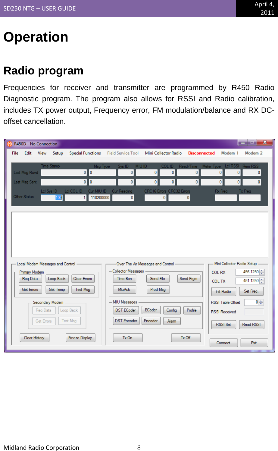
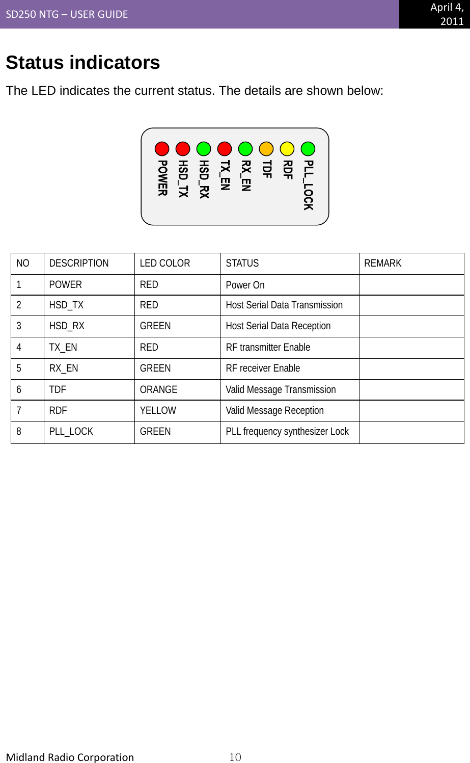
User Manual
Discussion / Help
Navigation