Neptune Technology Group SD250NTG LMR DATA RADIO User Manual Preliminary UG SD250NTGx
Neptune Technology Group Inc. LMR DATA RADIO Preliminary UG SD250NTGx
Users Manual
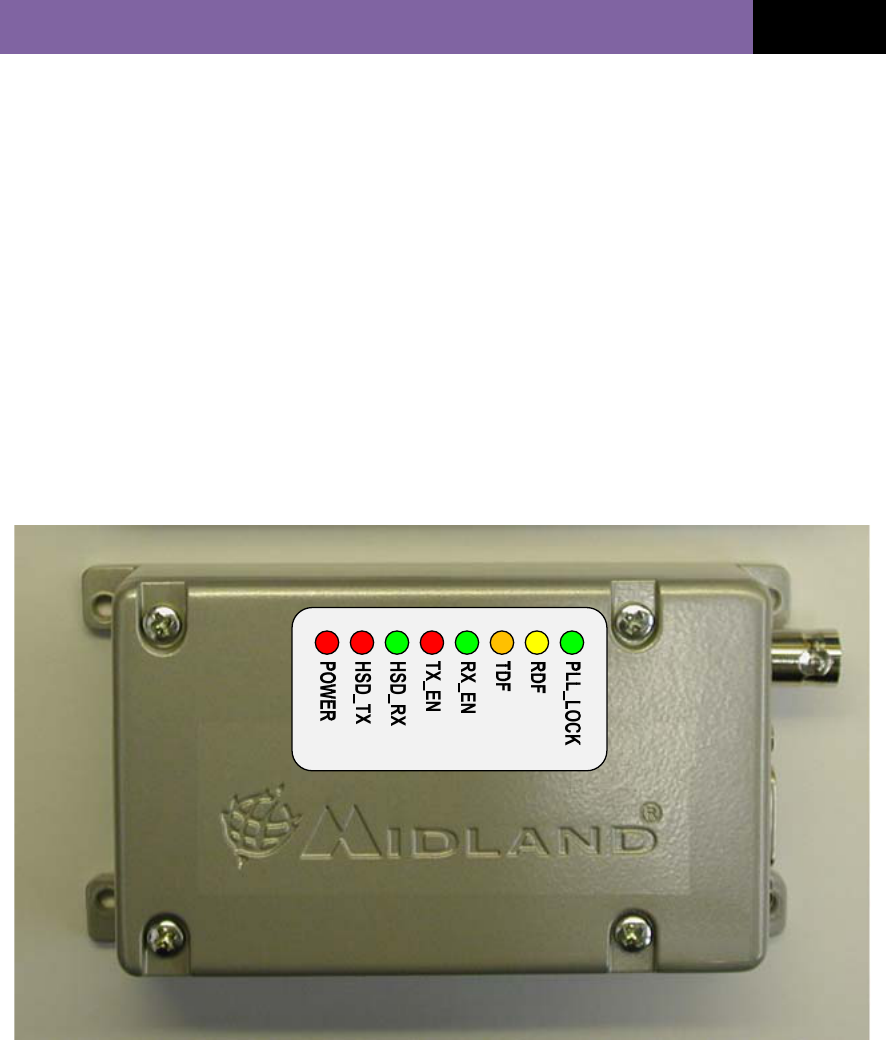
POWER
HSD_TX
HSD_RX
TX_EN
RX_EN
TDF
RDF
PLL_LOCK
SD-250NTG
User Guide

SD250NTG–USERGUIDEApril4,
2011
MidlandRadioCorporation
1
Contents
Introduction --- 2
Preparing for use
Unpacking and inspection --- 3
Description of modem --- 4
Features --- 5
External Connections --- 6
Pin Outs --- 7
Operation
Program Radio --- 8
Transmit/Receive Operation --- 9
Status Indicators --- 10
Installation
Antennas --- 11
Power sources --- 11
Cabling --- 12
Fixing --- 12
Safety and general information --- 13
Warranty and repairs --- 15
Care of the equipment --- 15
Disposal / Recycling --- 15

SD250NTG–USERGUIDEApril4,
2011
MidlandRadioCorporation
2
Introduction
The SD250NTG range is a 0.5 to 5 Watts RF data module at UHF frequencies.
The SD250NTG is housed in a rugged cast-aluminum box sealed to IEC 529
(IP54) making it suitable for a wide range of mobile and fixed applications.
The SD250 RF data module unit meets the essential requirements of the relevant
directives. In order to maintain this compliance the installation and safety
information must be adhered to at all times.
• The SD250 RF data module must only be installed where unintentional contact
cannot be made. The surface of the device may be hot to touch under certain
transmit conditions. The SD250 is not designed for permanent transmission. If
prolonged transmission periods are used, the unit will become hot and will
require an additional heat-sink to be fitted.
• When fitting the module into a fixed installation, care must be taken in the
routing of all cabling such that the insulation cannot become damaged.
• The recommended supply sources for use with the SD250NTG is a standard
12V / 2A dc supply, but is capable of operating in the range 9V - 18V.
SD250NTG–USERGUIDEApril4,
2011
MidlandRadioCorporation
3
Preparing for use
Unpacking and inspection
Unpack the modem and check that you have received the following items:
• SD250NTG RF data modem
• User Guide (this document)
If any of these items are missing, please contact your supplier.

SD250NTG–USERGUIDEApril4,
2011
MidlandRadioCorporation
4
Description of modem
The SD250NTG has been designed to be used in an advanced, highly robust,
two-way fixed base meter reading solution that delivers comprehensive usage
information through a secure, long-range wireless network.
The SD250NTG is a network free, point to point RF data modem that offers great
flexibility in varied applications where wireless data is needed. The modem
supports 7,200 baud GMSK modulation over the narrow band channel spacing,
12.5 KHz, and high speed data communication through RS 232 serial port.
The internal modem allows communication with a pc using RS 232 for the data
and control lines. For further details, please refer to the mini-collector manual.

SD250NTG–USERGUIDEApril4,
2011
MidlandRadioCorporation
5
Features
• Compact and rugged die cast box
• Resistant to dirt, dust and water ingress (IP54 rated)
• Network free, point to point communication
• 0.5 - 5 watt programmable output power
• Synthesized operation
• 12.5 channel spacing
• Internal GMSK modem
• Calibrated ‘RSSI’ output value
• 9 – 18 volt supply input
SD250NTG–USERGUIDEApril4,
2011
MidlandRadioCorporation
6
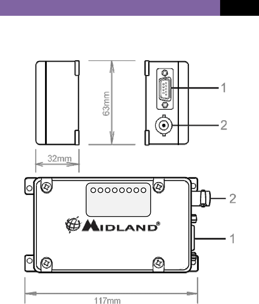
External Connections
POWER
HSD_TX
HSD_RX
TX_EN
RX_EN
TDF
RDF
PLL_LOCK
1. HD 15-way d-type (data, control signals and power supply)
2. BNC antenna connector
SD250NTG–USERGUIDEApril4,
2011
MidlandRadioCorporation
7
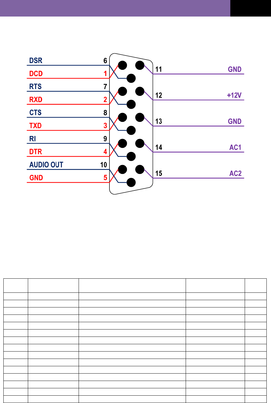
Pin Outs
DB-15 PIN OUT table with input and output levels
D-Type
Pin No. Function Description Signal Type Input/
Output
1 DCD Data Carrier Detect RS-232 O/P
2 RXD Received Data RS-232 O/P
3 TXD Transmitted Data RS-232 I/P
4 DTR Data Terminal Ready RS-232 I/P
5 GND Ground connection to chassis of the radio. 0V (Chassis)
6 DSR Data Set Ready RS-232 O/P
7 RTS Request To Send RS-232 I/P
8 CTS Clear To Send RS-232 O/P
9 RI Ring Indicator RS-232 O/P
10 AUDIO OUT Discriminated audio output Analog O/P
11 GND Ground connection to chassis of the radio. 0V (Chassis)
12 +12V Power supply input (Nominal 12V) 9.0V – 18.0V DC I/P
13 GND Ground connection to chassis of the radio. 0V (Chassis)
14 AC1 AC IN Analog I/P
15 AC2 AC IN Analog I/P
SD250NTG–USERGUIDEApril4,
2011
MidlandRadioCorporation
8
Operation
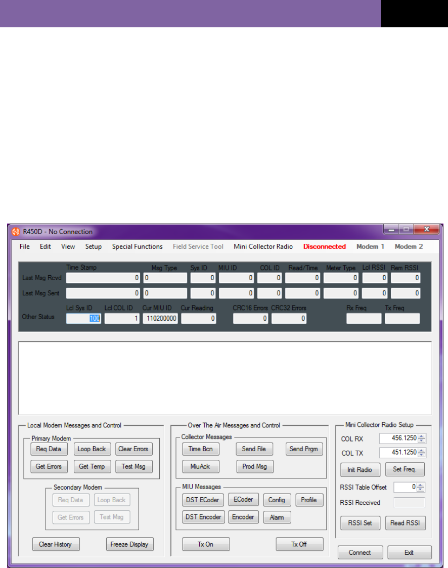
Radio program
Frequencies for receiver and transmitter are programmed by R450 Radio
Diagnostic program. The program also allows for RSSI and Radio calibration,
includes TX power output, Frequency error, FM modulation/balance and RX DC-
offset cancellation.

SD250NTG–USERGUIDEApril4,
2011
MidlandRadioCorporation
9
Transmit/Receive Operation
The SD250NTG is put into transmit/receive by using RS 232 leveled data. The
radio is controlled by existence of inputted data from a DTE. The data to be
transmitted is automatically stored while the transmitter is turned on and
transmitted after finishing preparation for transmission.
When the radio receives valid information over the air, then it is sent out to the
data terminal.
SD250NTG–USERGUIDEApril4,
2011
MidlandRadioCorporation
10
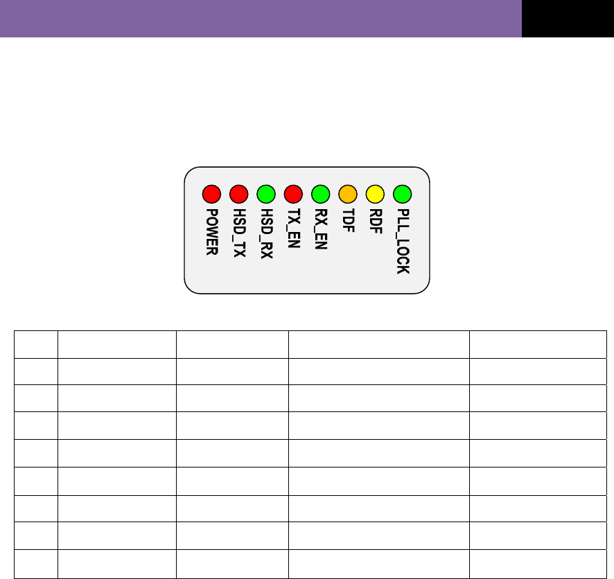
Status indicators
The LED indicates the current status. The details are shown below:
NO DESCRIPTION LED COLOR STATUS REMARK
1 POWER RED Power On
2 HSD_TX RED Host Serial Data Transmission
3 HSD_RX GREEN Host Serial Data Reception
4 TX_EN RED RF transmitter Enable
5 RX_EN GREEN RF receiver Enable
6 TDF ORANGE Valid Message Transmission
7 RDF YELLOW Valid Message Reception
8 PLL_LOCK GREEN PLL frequency synthesizer Lock

SD250NTG–USERGUIDEApril4,
2011
MidlandRadioCorporation
11
Installation
Antennas
It is important that any antennas are installed in a suitable location with an
adequate ground plane. Ideally, multiple antennas should be separated by a
minimum of a wavelength (at the lowest frequency), whilst still retaining a good
ground plane for each antenna. Therefore, for a 400MHz system, the ideal
separation should be a minimum of 0.75m.
Warning: If installing an antenna near people it is necessary to ensure the
minimum separation is maintained. This is particularly important where prolonged
exposure is likely.
Power sources
It is important that a “clean” source of power is used for the 12V supply to the
modem
SD250NTG–USERGUIDEApril4,
2011
MidlandRadioCorporation
12
Cabling
If possible, run RF cables separately from other cables and keep RF cables apart
from one another to avoid interference / coupling.
When fitting the modem into a fixed installation care must be taken in the routing
of all cabling such that the insulation cannot become damaged.
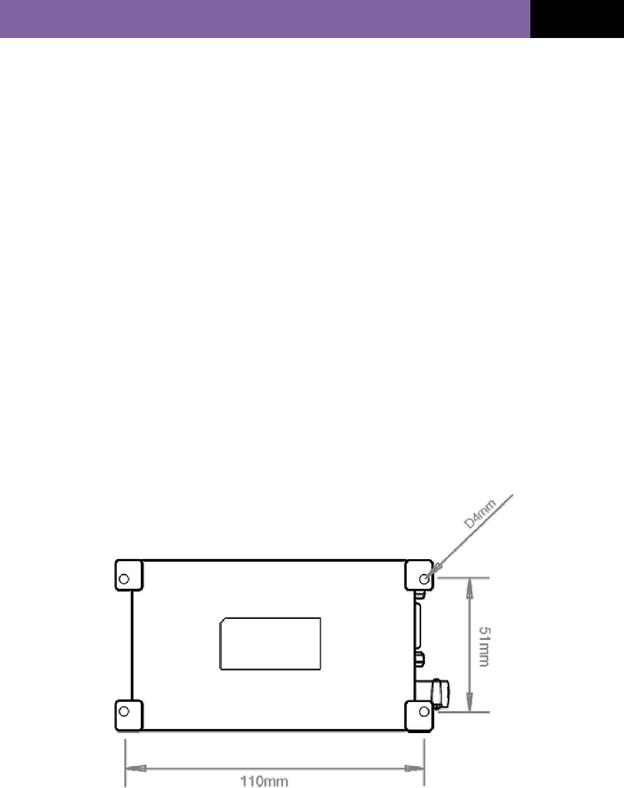
Fixing
We recommend that the SD250 is securely fixed to a surface, either directly, or
with a suitable bracket. The fixing hole center dimensions are as shown.
The modem can be attached to any surface by using suitable size screws
through the M3 holes in the mounting flanges.
Note: We do not recommend that the SD250 is fixed by cable ties to any wiring
looms.

SD250NTG–USERGUIDEApril4,
2011
MidlandRadioCorporation
13
Safety and general information
Important information on safe and efficient use of your Radio device
Exposure to radio frequency energy
Your modem is a high power radio transceiver. When it is on, it receives and also
sends out radio frequency (RF) signals. To help minimize human exposure to RF
electromagnetic energy, keep transmission time to 50% or less.
As with all radio devices, holding the antenna affects transmission quality and
may cause the radio to operate at a higher power level than required. Do not hold
the antenna when the radio is in use.
Do not use radios with damaged or modified antenna, this may violate
compliance with relevant international standards.
Where prolonged human exposure is likely, the minimum separation from the
antenna should be 0.8m.
Electromagnetic interference/compatibility
Most modern electronic equipment is shielded from RF energy. However certain
electronic equipment may not be shielded against RF signals. The modem needs
to be switched off in any facility where posted notices instruct you to do so to
avoid electromagnetic interference or compatibility conflicts. Special care should
be taken near facilities such as hospitals or health care centers may be using
equipment that is sensitive to external RF energy.
Medical devices (Pacemakers)
If you use any personal medical device, consult the manufacturer of your device
to determine it is adequately shielded from RF energy. Your physician may be
able to assist you in obtaining this information.

SD250NTG–USERGUIDEApril4,
2011
MidlandRadioCorporation
14
Vehicles with airbags
Air bags inflate with great force. Do not place a radio in the area over an airbag
or in the airbag deployment area, any radio may be propelled with great force
and cause serious injury to the occupant of the vehicle.
Potentially explosive atmospheres
Turn off your modem prior to entering any area with a potentially explosive
atmosphere, unless it is a radio type especially qualified for use in such areas.
Do not remove install or charge batteries in such areas. Sparks in potentially
explosive atmospheres can cause an explosion or fire resulting in bodily injury or
death.
Potentially explosive atmospheres include fuelling areas such as petrol stations,
below decks on boats, fuel or chemical transfer or storage facilities, vehicles
using liquid petroleum gas (such as propane or butane); areas where the air
contains chemicals or particles such as grain, dust or metal powders, and any
other area where you would normally be advised to turn off your vehicle engine.
Areas with potentially explosive atmospheres are often but not always posted.

SD250NTG–USERGUIDEApril4,
2011
MidlandRadioCorporation
15
Warranty and repairs
The SD250 is a low maintenance device. Once installed it requires no ongoing
maintenance.
In the event that your SD250 RF data module needs repair, return your radio to
an authorized Midland Radio supplier. Do not disassemble, modify or repair the
unit unless the work is carried out by a Midland Radio approved supplier.
Incorrect assembly, modification or repair may cause irreparable damage to your
unit and will invalidate any warranty.
Care of the equipment
Do not immerse the SD250 RF data module in water or other fluids.
Do not use solvents or spirits for cleaning as this may cause damage to the case
materials.
Do not over tighten connection to the modem.
Disposal / Recycling
The SD250 is a Class 3 product in accordance with the Waste of Electrical and
Electronic Equipment (WEEE) Directive. Disposal of this class of equipment must
be carried out through an authorized recycling centre or contact your supplier.
FCC warnings:

SD250NTG–USERGUIDEApril4,
2011
MidlandRadioCorporation
16
Published by Midland Radio Corp.
Any queries regarding information in this manual, please contact the Technical
Services Group Leader at the above address.
Information provided in this document is believed correct at time of printing but is
subject to change without notice.
Midland Radio will not accept liability for any loss, damage or costs howsoever
caused as a result of the information provided.