NetComm Wireless NRB51 Outdoor LTE Router User Manual
NetComm Wireless Limited Outdoor LTE Router
UserManual.wiki
>
NetComm Wireless
>
NRB51 User Manual
User Manual
Navigation menu
Upload a User Manual
Namespaces
Wiki Guide
HTML
PDF
Info
Views
User Manual
Discussion / Help
Navigation
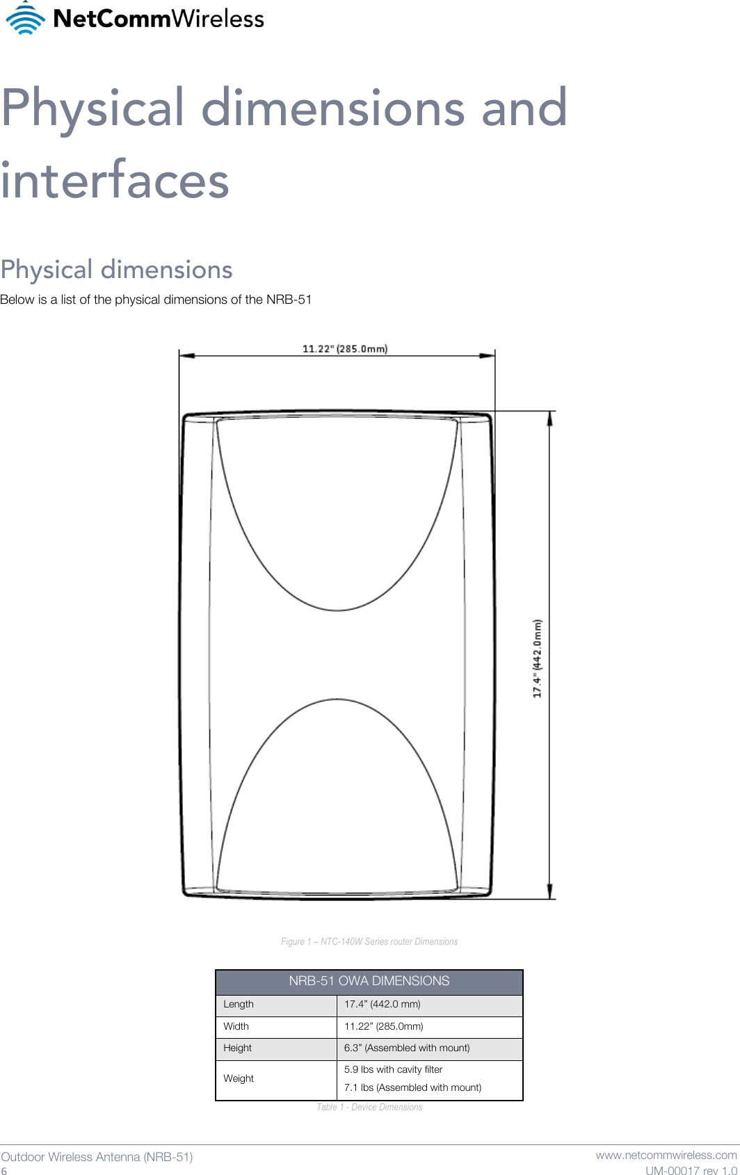
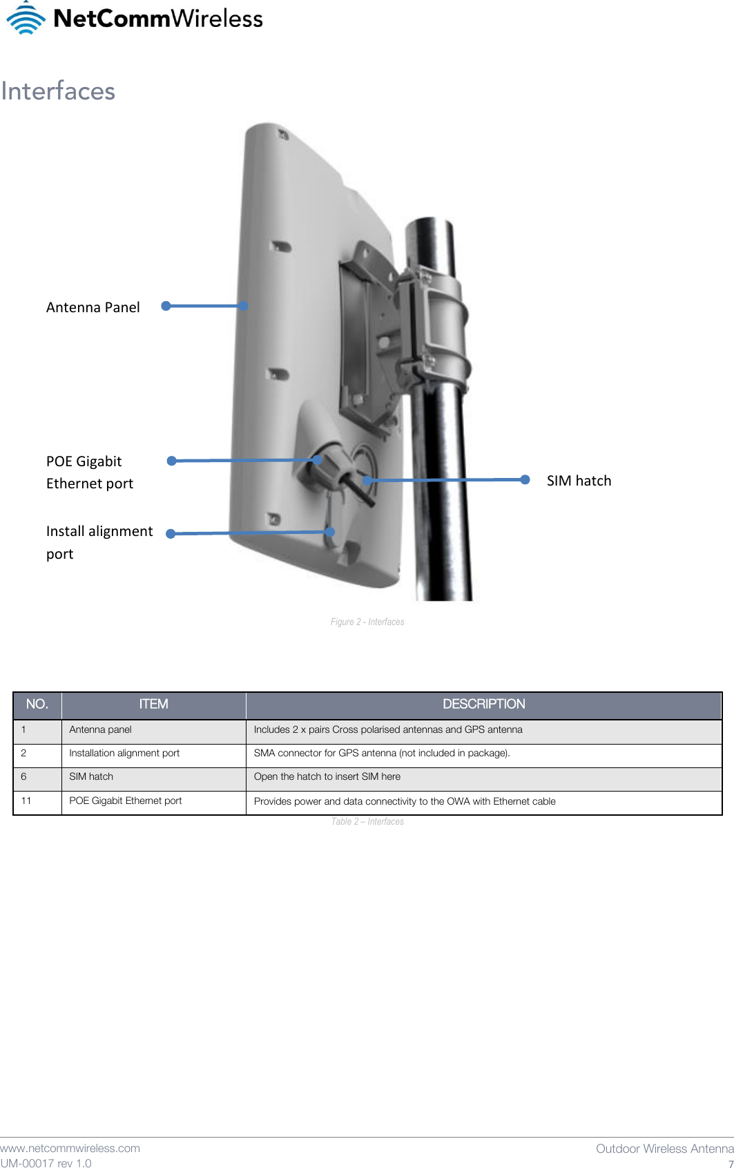
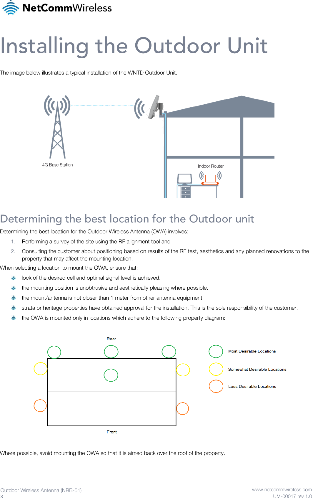
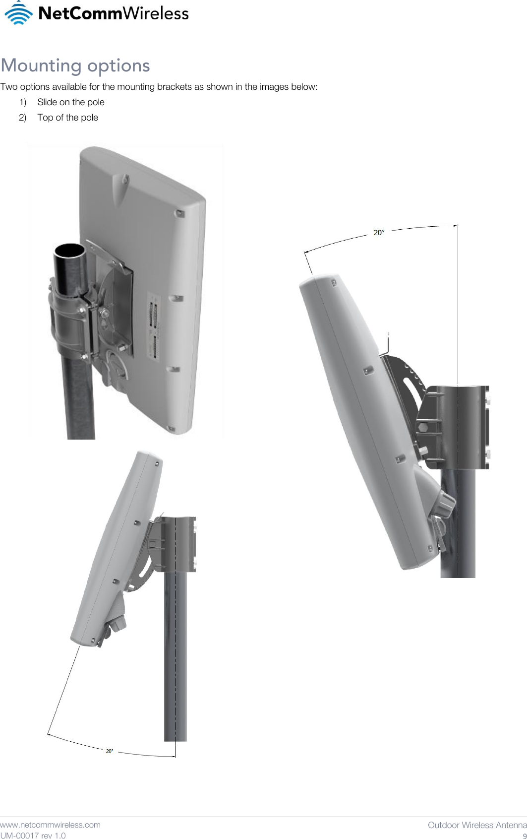
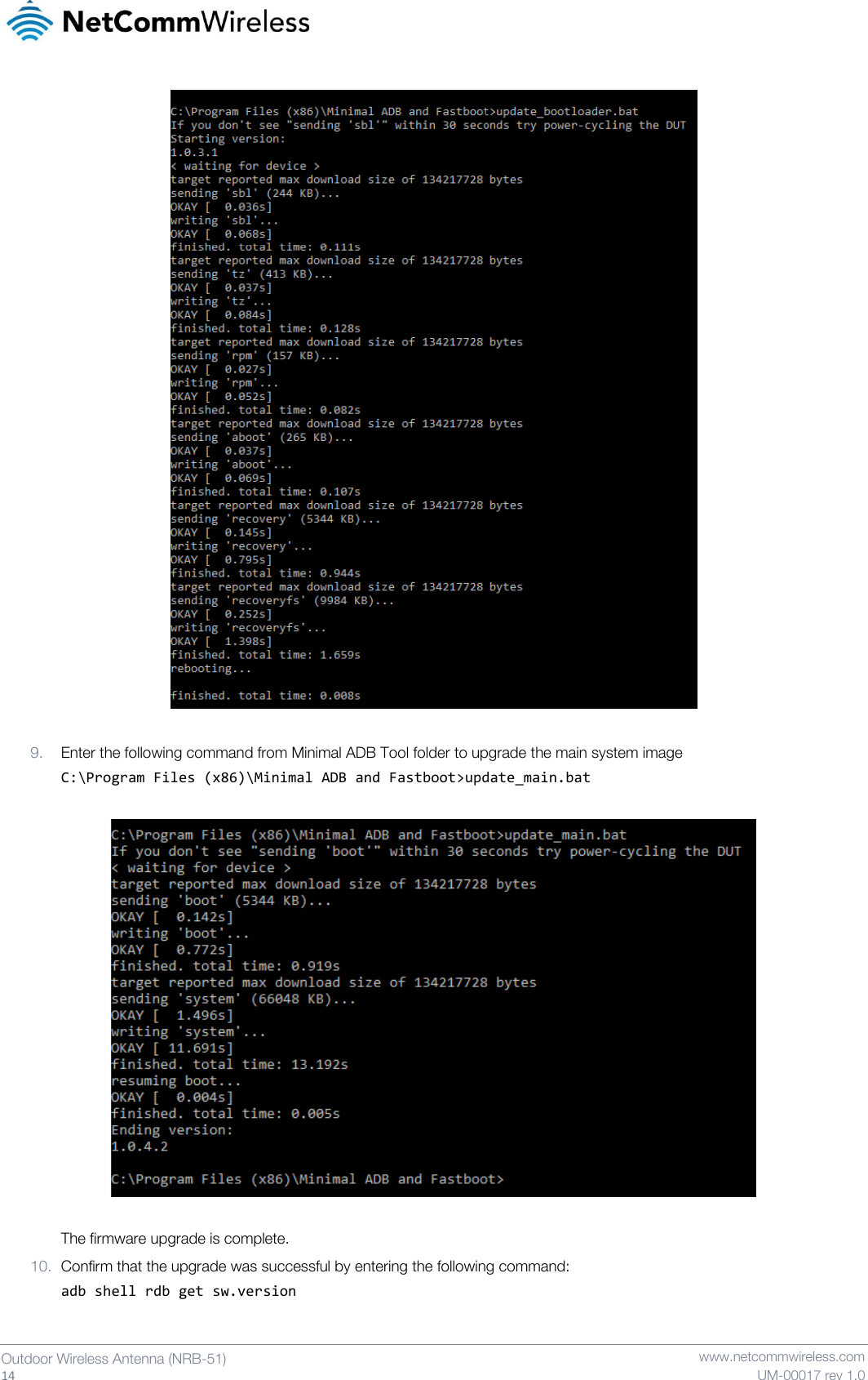
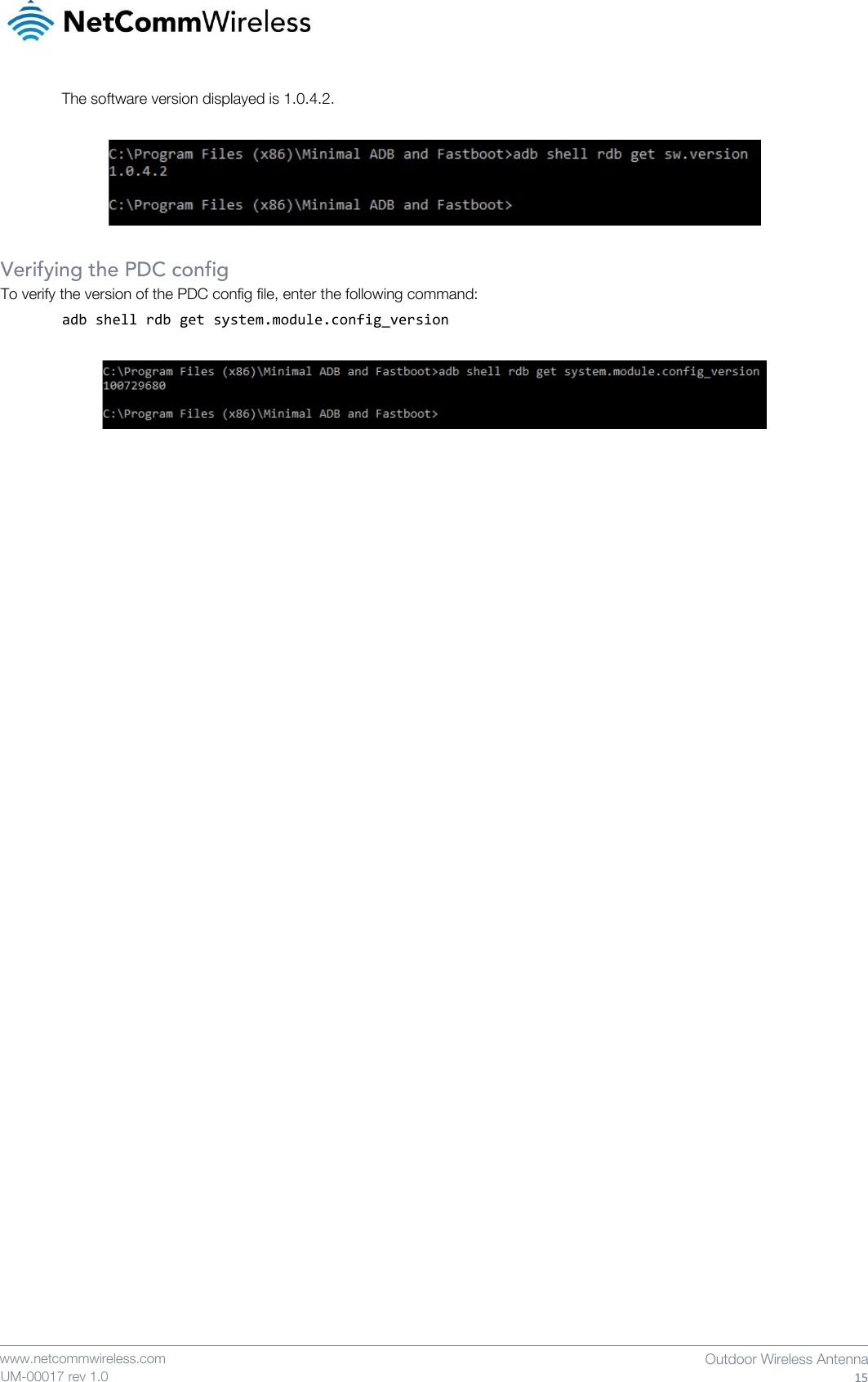
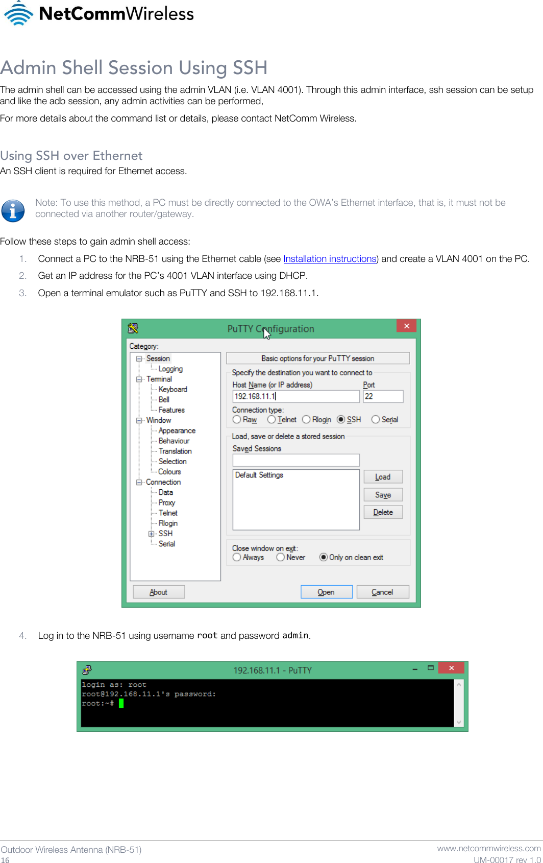
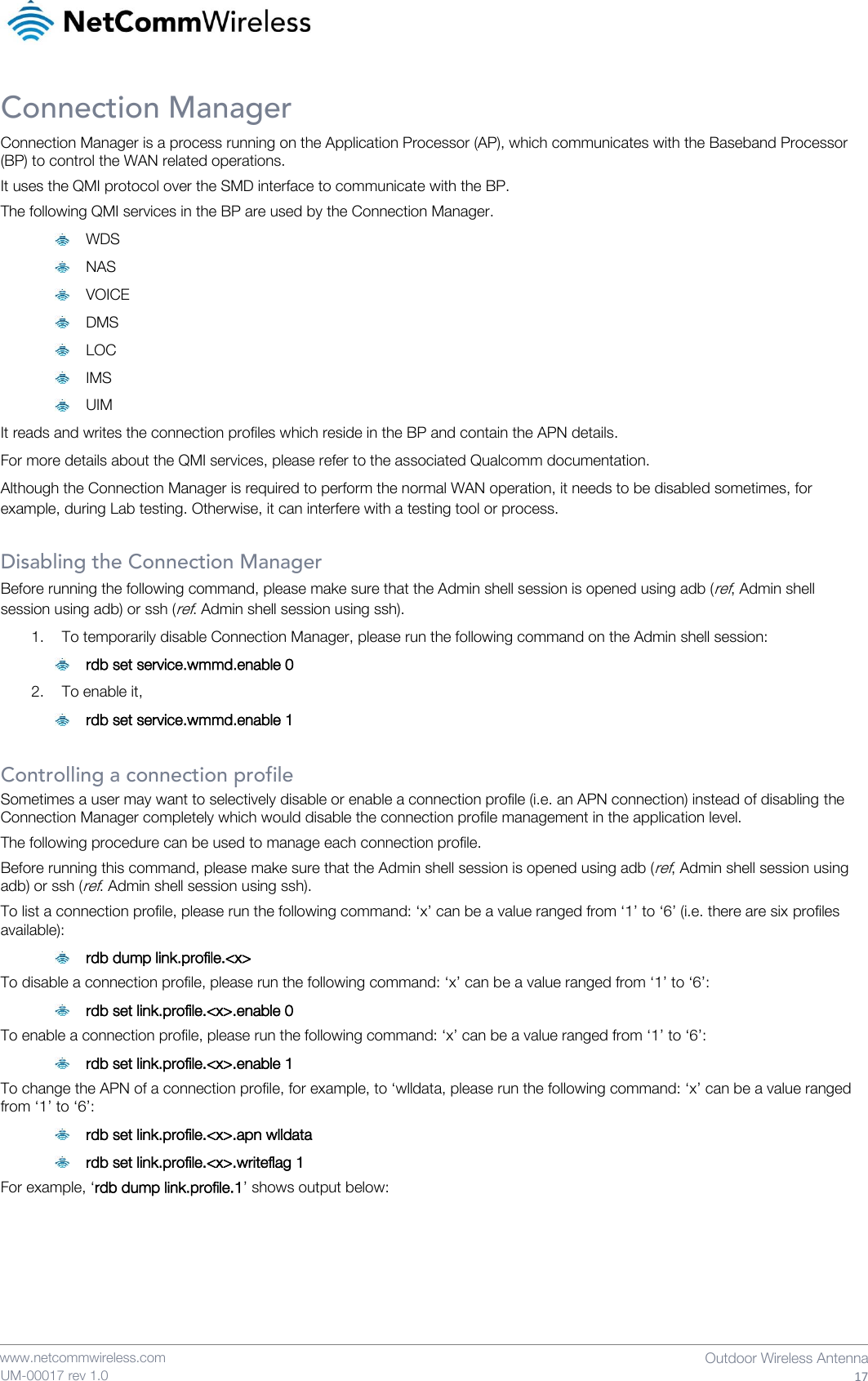
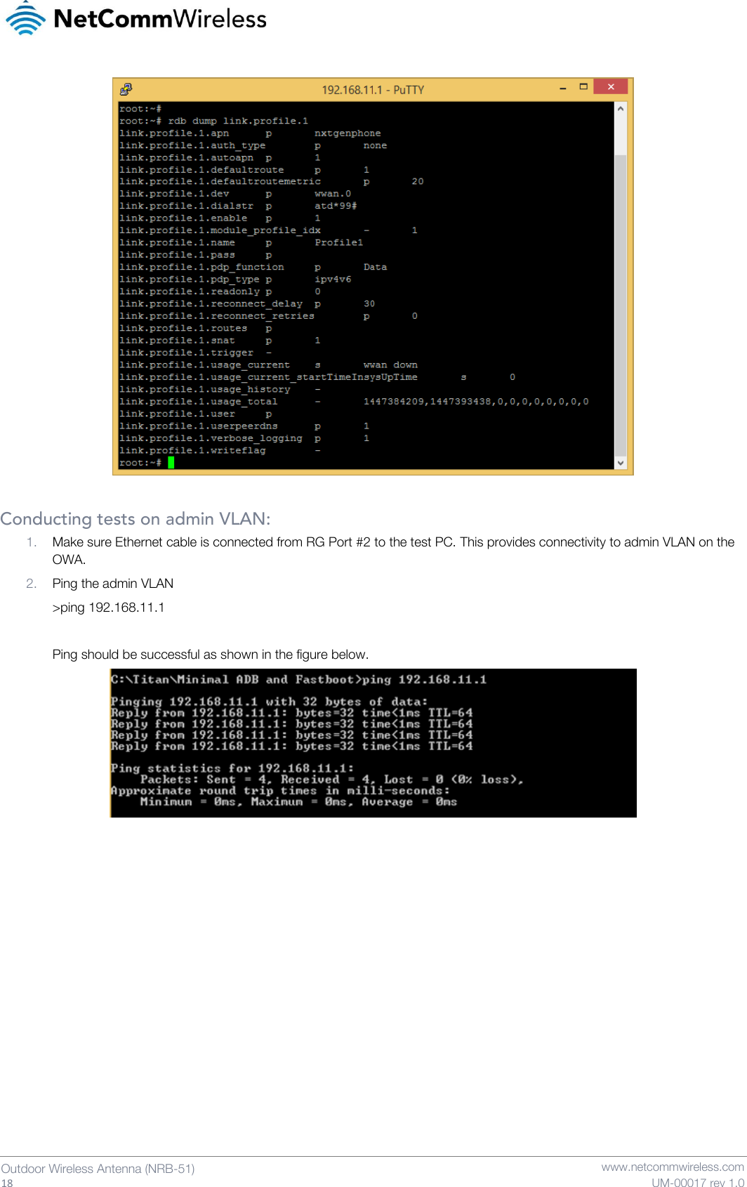
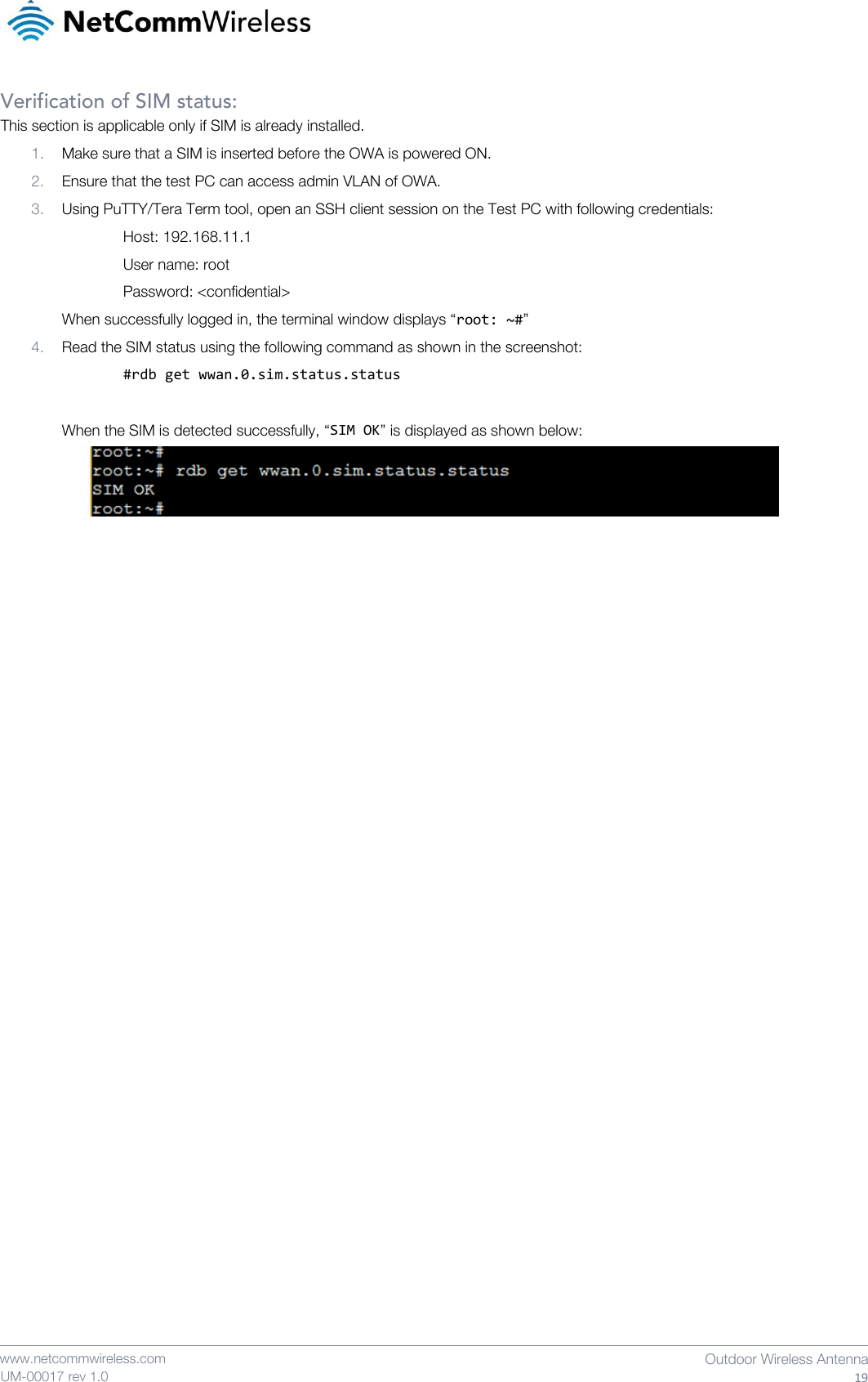
![20 Outdoor Wireless Antenna (NRB-51) www.netcommwireless.com UM-00017 rev 1.0 Useful Commands VLAN details adb shell rdb dump vlan.admin adb shell rdb dump vlan.data adb shell rdb dump vlan.ems adb shell rdb dump vlan.voice WWAN status adb shell rdb dump wwan.0.system_network_status SIM status adb shell rdb dump sim IMEI adb shell rdb dump imei IMS status adb shell rdb dump wwan.0.ims Data Profile adb shell rdb dump link.profile.1 adb shell rdb dump link.profile.1.apn Voice (IMS) profile adb shell rdb dump link.profile.2 SOS profile adb shell rdb dump link.profile.3 EMS profile adb shell rdb dump link.profile.4 To change an APN name, adb shell rdb set link.profile.1.apn [new apn] adb shell rdb set link.profile.1.writeflag 1 To change an APN’s IP type, adb shell rdb set link.profile.1.pdp_type [ipv4|ipv6|ipv4v6] adb shell rdb set link.profile.1.writeflag 1 To enable and disable, an APN state adb shell rdb set link.profile.1.enable 1 adb shell rdb set link.profile.1.enable 0 Check the interface status](https://usermanual.wiki/NetComm-Wireless/NRB51/User-Guide-2922412-Page-20.png)