NetComm Wireless NTC140 LTE M2M Router User Manual
NetComm Wireless Limited LTE M2M Router
Contents
- 1. user manual
- 2. User Manual
User Manual
Quick Start Guide
4G M2M Router
NTC-140

| Industrial IoT
2
Quick start guide
This quick start guide is designed to get you up and running quickly with your new
NTC-140 router. More advanced set up instructions are provided in the user guide
which can be opened by clicking on the Help tab on the web user interface, or
can be downloaded from
https://www.netcommwireless.com/product/4g-m2m-router
Package contents
All NTC-140 packages include:
1 x NetComm NTC-140 router
2 x 3G/4G antennas
1 x 1.5m Black Ethernet cable
1 x DIN rail mounting bracket
1 x Quick start guide
1 x Power supply cable with tted Molex connector
| Industrial IoT
3
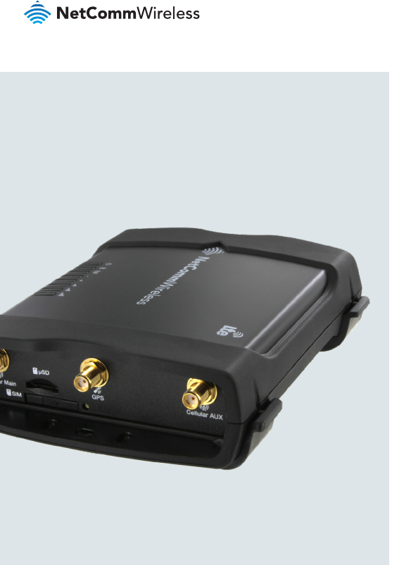
NTC-140 - 4G M2M Router
-
i
I/O
GPS
USB LAN LAN/WAN
Cellular Main
SIM
µSD
Cellular AUX
+
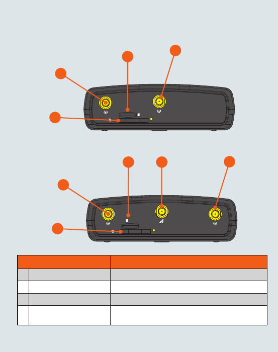
Device overview
ITEM DESCRIPTION
13G/4G antenna connectors SMA female connector for 3G/4G antennas.
2GPS antenna connector SMA female connector for GPS antenna.
3SIM card slot Insert SIM card here.
4MicroSD card slot Insert a MicroSD card here to provide additional storage
(Optional).
2
1
3
1
4
NTC-140-01
-
i
I/O
USB LAN LAN/WAN
Cellular Main
SIM
µSD Cellular AUX
+
1
3
1
4
NTC-140-02
| Industrial IoT
4
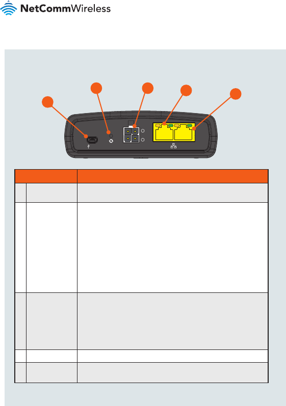
ITEM DESCRIPTION
1Mini USB 2.0
OTG port
Provides connectivity for optional external storage or a USB Ethernet
dongle. Supplies up to 0.5A to connected device.
2Reset button Press and hold for less than 5 seconds to reboot to normal mode.
The LEDs are green and extinguish in sequence to indicate that the
router will reboot normally if the button is released during this period.
Press and hold for 5 to 15 seconds to reboot to recovery mode.
The LEDs are amber and extinguish in sequence to indicate that the
router will reboot to recovery mode if the button is released during
this period.
Press and hold for 15 to 20 seconds to reset the router to factory
default settings. The LEDs are red and extinguish in sequence to
indicate that the router will reset to factory default settings if the
button is released during this period.
3Molex Mini-Fit™
receptacle
Connect the provided power supply here. The Molex receptacle
provides:
• Ground (−)
• Power (+)
• I/O terminal
• (i) ignition input detection terminal.
4LAN port LAN port for wired Ethernet clients.
5LAN/WAN port LAN or WAN port for wired Ethernet clients or to bridge another
network connection.
-
i
I/O
GPS
USB LAN LAN/WAN
Cellular Main
SIM
µSD
Cellular AUX
+
1
25
34
NTC-140-01 / NTC-140-02
| Industrial IoT
5
NTC-140 - 4G M2M Router
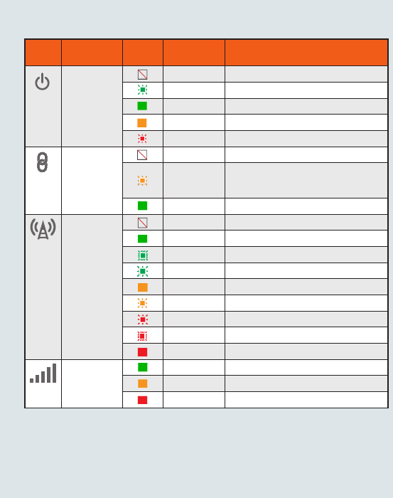
Overview of LED indicators
LED
ICON
NAME
COLOR
STATE DESCRIPTION
Power Off Power off
Double ash Powering up
On Power on
On Power on in recovery mode
Slow ashing Hardware error, such as SIM not inserted.
GPS1/
Customisable
LED
Off GPS function disabled
Slow ashing GPS function is enabled but no satellite
detected
On Satellite detected, location acquired
Network Off Radio Off
On Connected via WWAN
Blinking2Trafc via WWAN
Slow ashing Connecting PDP
On Registered on Network
Slow ashing Registering network
Slow ashing SIM PIN locked
Fast ashing SIM PUK locked
On Can’t connect
Signal
strength
On LTE signal
On WCDMA signal
On GSM signal
1 GPS is only available on the NTC-140-02
2 The term “blinking” means that the LED may pulse, with the intervals that the LED is on and off not being equal. The
term “ashing” means that the LED turns on and off at equal intervals.
| Industrial IoT
6
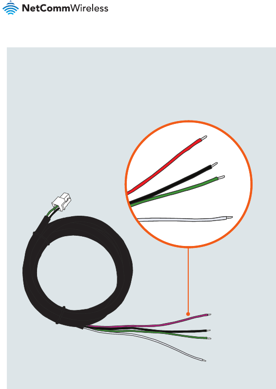
Power supply cable
The included power supply cable has colour-coded breakout wires which can be
terminated to provide power, ignition detection and input/output functionality.
The picture below outlines the polarity and functions of the wires.
Power
(+) Ground
(−)
I/O
Ignition
| Industrial IoT
7
NTC-140 - 4G M2M Router
-
i
I/O
GPS
USB LAN LAN/WAN
Cellular Main
SIM
µSD
Cellular AUX
+
Installing your device
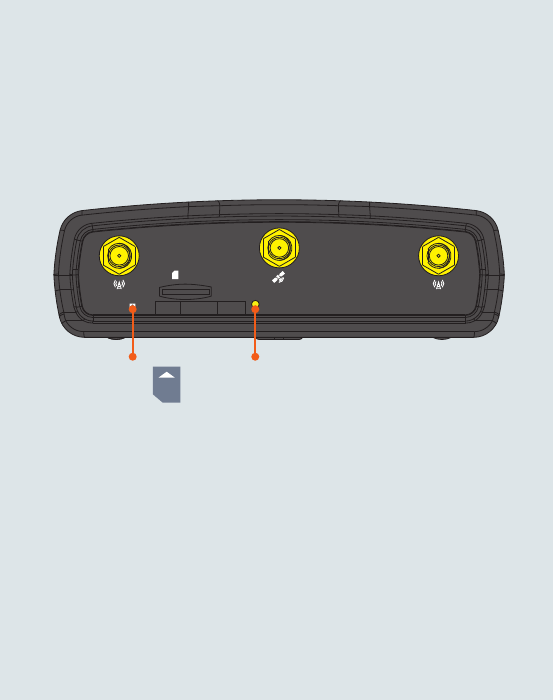
Step 1: Insert the SIM card
Using a paper clip, press the SIM Eject button to eject the SIM card tray. Place the
SIM card in the tray and then insert the loaded tray into the SIM slot with the gold
side facing up, as shown below.
Insert
SIM
Card
Press the SIM
Eject Button
| Industrial IoT
8
-
i
I/O
GPS
USB LAN LAN/WAN
Cellular Main
SIM
µSD
Cellular AUX
+
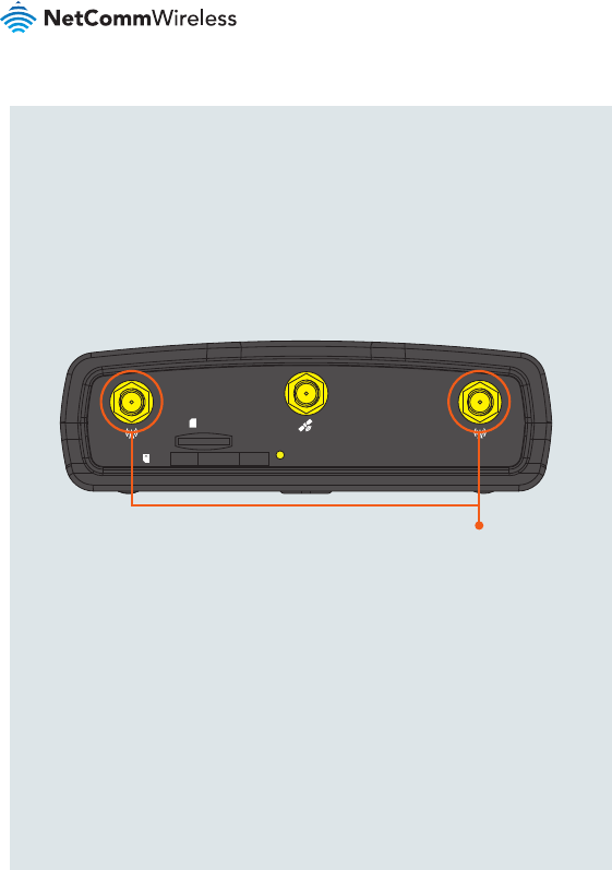
Step 2: Attach the antennas
The NTC-140 router is shipped with caps on the LTE and GPS* antenna sockets.
To attach the supplied antennas, rst remove the antenna socket caps from the
Main and Auxiliary antenna sockets by turning them in an anti-clockwise direction,
then screw the antennas onto the sockets by turning them in a clockwise direction.
Please refer to the Device overview section for the antenna socket layout. If you
have purchased a GPS antenna, remove the socket cap from the GPS antenna
socket and attach the antenna to the socket in the same manner.
Remove caps
then screw
antennas on
*GPS is only available on the NTC-140-02
| Industrial IoT
9
NTC-140 - 4G M2M Router
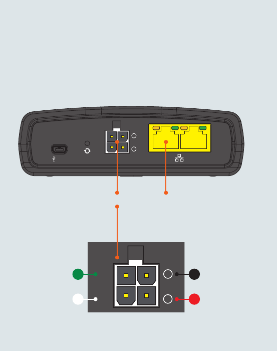
Step 3: Connect the power and Ethernet cables
Connect the included power supply cable to the Molex Mini-Fit™ receptacle
and then connect the green and white breakout wires to the ignition and I/O
connections as required. Connect the Power (red) and the Ground (black) wires to
your power source. The power LED on the router lights up when a power source
is connected.
Attach the supplied Black Ethernet cable to the LAN Ethernet port on your router
and the other end to your computer.
-
i
I/O
GPS
USB LAN LAN/WAN
Cellular Main
SIM
µSD
Cellular AUX
+
-
i
I/O
GPS
USB LAN LAN/WAN
Cellular Main
SIM
µSD
Cellular AUX
+
Connect
Ethernet
Cable
Ground
Power
Molex Mini-Fit™
I/O
Ignition
| Industrial IoT
10
Step 4: Access the router’s web interface
In your web browser’s address bar enter http://192.168.1.1/ or http://my.router/.
The login page is displayed.
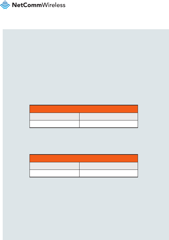
There are two system management accounts (Root Manager and Admin) with
different management capabilities.
Root Manager account
Grants full privileges such as rmware upgrades, device conguration, backup
and restore, and reset to factory default settings. To access the Root Manager
account, use these login details.
http://192.168.1.1 or http://my.router
Username root
Password admin
Admin account
Allows updates to general settings. To access the Admin account, use these
login details.
http://192.168.1.1 or http://my.router
Username admin
Password admin
Enter the username and password for the admin or root manager account and
click Log in. The Status page is displayed.
| Industrial IoT
11
NTC-140 - 4G M2M Router
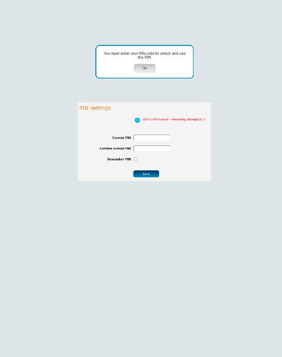
Step 5: Unlock the SIM card
If the inserted SIM card is PIN locked, a pop-up window is displayed informing you
that you must unlock the SIM before use.
Click the OK button. The SIM Security page is displayed.
In the Current PIN eld, enter the SIM PIN and then enter it again in the Conrm
current PIN eld. If you do not want to enter the PIN code each time the SIM
is inserted, select the Remember PIN option. Click the Save button. After a
moment, the router displays “Success! The SIM unlock was successful”.
| Industrial IoT
12
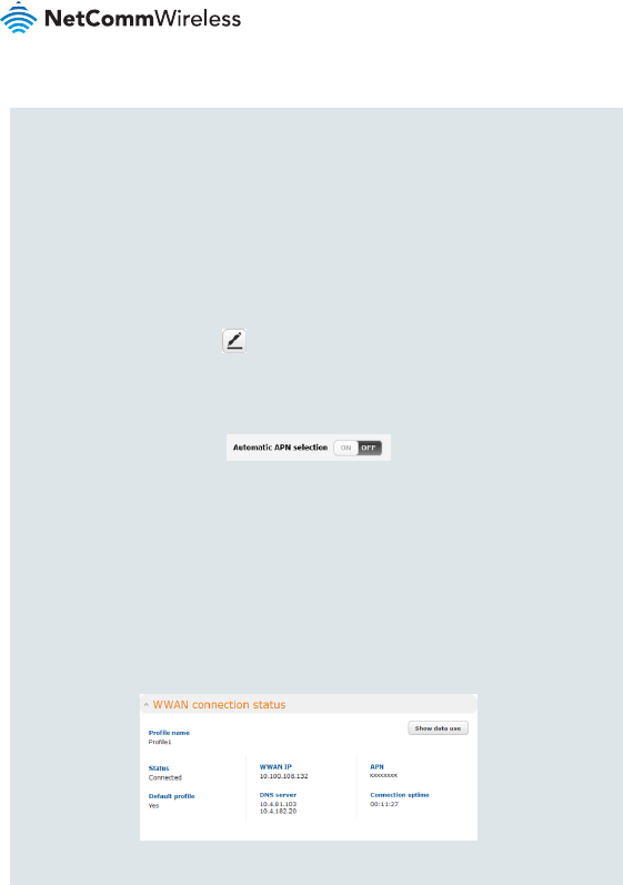
Step 6: Connect to the Internet
If the SIM Status is OK, the NTC-140 router automatically attempts to connect to
the Internet by detecting the correct APN and connection details.
If automatic conguration was unsuccessful, you must manually enter the
connection details.
To manually congure the connection prole:
1. From the top menu bar, select the Networking option.
2. Next to Prole1, click the button. The Data connection prole settings
screen is displayed.
3. Ensure that the Automatic APN selection toggle key is set to the
OFF position.
4. In the APN eld, enter the APN name that your carrier requires for mobile
broadband connection. If required, enter the Username and Password in the
Username and Password elds. Click the Save button.
The connection prole is now congured.
Verifying the connection status
Click on the Status menu item from the top menu bar. The Status page is
displayed. The mobile broadband connection is established successfully if the
Status eld in the WWAN connection status section displays Connected.

| Industrial IoT
13
NTC-140 - 4G M2M Router
Step 7: Mount the router
Mount your router in a suitable location using the options listed in the Mounting
options section.
When selecting a location to mount the NTC-140 router, keep in mind that it
features high performance antennas designed to provide optimum signal strength
in a wide range of environments. You can check the signal strength by observing
the colour and number of LEDs illuminated on the front of the device. For a precise
reading of the signal strength, refer to the Status page on the web user interface.
If you nd the signal strength is weak, try moving the router to a different place,
mounting it differently or changing the orientation of the antennas.
The signal strength LEDs update within a few seconds with a rolling average signal
strength reading. When selecting a location for the router, please allow up to 20
seconds for the signal strength LEDs to update before repositioning.
Congratulations - your NTC-140 router is now ready to use!
| Industrial IoT
14
Mounting your device
Depending on your individual setup, you may need certain components to mount
your device correctly, such as additional fasteners and screwdrivers for specic
wall or rail mounting.
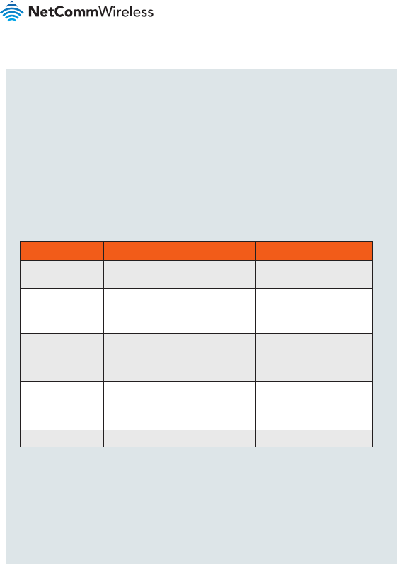
Mounting options
The NetComm Wireless NTC-140 router can be installed quickly and easily in a
variety of locations.
MOUNT TYPE DESCRIPTION BENEFITS
Wall mount Flat against the wall Slimline form factor, close
to wall
Wall mount via
DIN rail mounting
bracket
DIN Rail mounting bracket is secured
to the wall and the router is attached
to the mounting bracket.
Easy to remove
DIN rail mount
DIN Rail mounting bracket is slid or
snapped on to the DIN Rail and the
router is attached to the mounting
bracket.
Simplicity, easy to remove.
Pole mount via
DIN rail mounting
bracket
DIN Rail mounting bracket is secured
to a pole or other xed object using
cable ties and the router is attached
to the mounting bracket.
Easy to remove, exibility
of orientation, variety of
objects to which the router
may be mounted.
Desk mount Stand on a desk Simplicity, versatility
| Industrial IoT
15
NTC-140 - 4G M2M Router
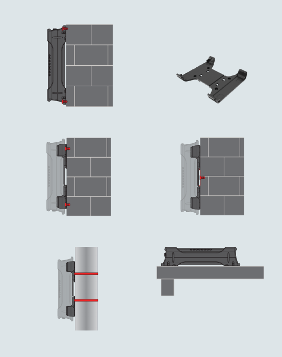
Wall mount DIN Rail mounting bracket
V Bend allows you to snap the DIN
bracket onto the middle of a DIN rail
rather than sliding it onto the end.
Wall Mounted via DIN Rail Bracket DIN Rail mount
Pole mount using DIN Rail bracket Desk mount
| Industrial IoT
16
Conguring multiple devices
To apply your advanced conguration settings to more than one NTC-140 router,
follow these simple steps.
Step 1
Back up your router’s conguration
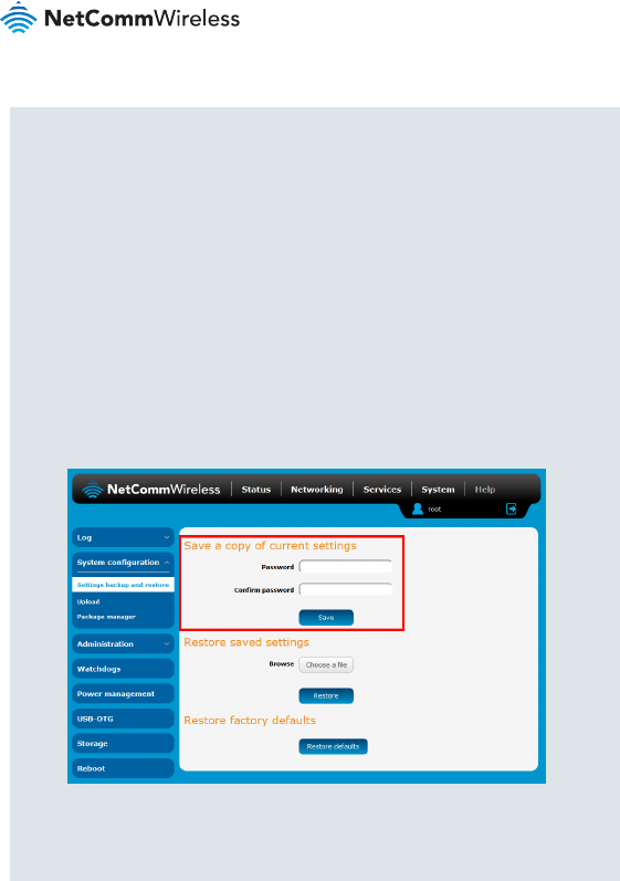
Log in to the web conguration interface, click on the System menu, select
System conguration and click on Settings backup and restore.
If you want to password protect your backup conguration les, enter your
password in the elds under Save a copy of current settings and click on Save.
If you don’t want to password protect your les, just click on Save. The router will
then prompt you to select a location to save the settings le.
| Industrial IoT
17
NTC-140 - 4G M2M Router
Step 2
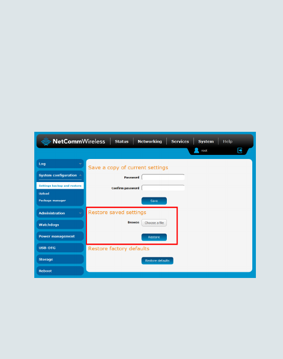
Restore your backup conguration
In the web conguration interface click on the System menu, select System
conguration and click on Settings backup and restore.
From the Restore saved settings section, click on Choose a le and select the
backup conguration le on your computer.
Click Restore to copy the settings to the new NTC-140 router. The router will
apply these settings and inform you it will reboot - click on OK.
Tip: Don’t change the le extension of the backup le as this may cause it
to corrupt.

| Industrial IoT
18
Regulatory information
NTC-140-01
FCC regulations
Federal Communications Commission Notice (United States): Before a wireless
device model is available for sale to the public, it must be tested and certied to
the FCC that it does not exceed the limit established by the government-adopted
requirement for safe exposure.
This device complies with part 15 of the FCC Rules. Operation is subject to the
following two conditions:
(1) This device may not cause harmful interference, and
(2) this device must accept any interference received, including interference that
may cause undesired operation.
This device has been tested and found to comply with the limits for a Class B
digital device, pursuant to Part 15 of the FCC Rules. These limits are designed
to provide reasonable protection against harmful interference in a residential
installation. This equipment generates, uses and can radiate radio frequency
energy and, if not installed and used in accordance with the instructions,
may cause harmful interference to radio communications. However, there is
no guarantee that interference will not occur in a particular installation. If this
equipment does cause harmful interference to radio or television reception, which
can be determined by turning the equipment off and on, the user is encouraged to
try to correct the interference by one or more of the following measures:
• Reorientate or relocate the receiving antenna.
• Increase the separation between the equipment and receiver.

| Industrial IoT
19
NTC-140 - 4G M2M Router
• Connect the equipment into an outlet on a circuit different from that to which the
receiver is connected.
• Consult the dealer or an experienced radio/TV technician for help.
Changes or modications not expressly approved by the party responsible for
compliance could void the user‘s authority to operate the equipment.
RF Exposure
Your device contains a transmitter and a receiver. When it is on, it receives and
transmits RF energy. When you communicate with your device, the system
handling your connection controls the power level at which your device transmits.
• This device meets the government’s requirements for exposure to radio waves.
• This device is designed and manufactured not to exceed the emission limits
for exposure to radio frequency (RF) energy set by the Federal Communications
Commission of the U.S. Government.
• This device complies with FCC radiation exposure limits set forth for an
uncontrolled environment. To ensure compliance with RF exposure guidelines the
device must be used with a minimum of 24cm separation from the body. Failure to
observe these instructions could result in your RF exposure exceeding the relevant
guideline limits.
External antenna (transmitters equipped with detachable antennas)
Any external antenna used for this transmitter must be installed to provide a
separation distance of at least 24cm from all persons and must not be co-located
or operated in conjunction with any other antenna or transmitter. Please consult
the health and safety guide of the chosen antenna for specic body separation
guidelines as a greater distance of separation may be required for high-gain
antennas.
Any external antenna gain must meet RF exposure and maximum radiated output
power limits of the applicable rule section. The maximum antenna gain for this
device as reported to the FCC is:
| Industrial IoT
20
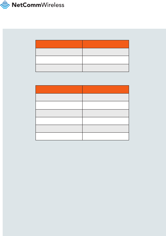
FREQUENCY (MHz) GAIN (dBi)
704 - 798 1.6
824 - 960 1
1710 - 2170 3.7
with ANT-0024
with ANT-0050 (0.6m cable losses included)
Company Contact Details
NetComm Wireless Limited, 1000 Sawgrass Corporate Parkway, Suite 500
Sunrise, Florida 33323, USA
Phone: +1 320 566 0316
IC regulations
This Class B digital apparatus complies with Canadian ICES-003.
Cet appareil numérique de la classe B est conforme à la norme NMB-003 du
Canada.
This device complies with Industry Canada licence-exempt RSS standard(s).
FREQUENCY (MHz) GAIN (dBi)
824 - 849 5.65
817 - 823 5.65
777 - 787 1.66
704 - 716 1.66
1710 - 1755 3.66
1850 - 1915 4.17

| Industrial IoT
21
NTC-140 - 4G M2M Router
Operation is subject to the following two conditions:
Le présent appareil est conforme aux CNR d’Industrie Canada applicables
aux appareils radio exempts de licence. L’exploitation est autorisée aux deux
conditions suivantes:
(1) this device may not cause interference, and
(1) l’appareil ne doit pas produire de brouillage, et
(2) this device must accept any interference, including interference that may cause
undesired operation of the device.
(2) l’utilisateur de l’appareil doit accepter tout brouillage radioélectrique subi, même
si le brouillage est susceptible d’en compromettre le fonctionnement.”
RF Exposure Information (MPE):
This device has been tested and meets applicable limits for Radio Frequency (RF)
exposure. /
Cet appareil a été testé et répond aux limites applicables en matière d’exposition
aux radiofréquences (RF).
This equipment should be installed and operated with minimum distance 24 cm
between the radiator & your body. / Cet équipement doit être installé et utilisé avec
une distance minimale de 24 cm entre le radiateur et votre corps.
External antenna - RSS-Gen 8.3 (transmitters equipped with
detachable antennas)
This radio transmitter has been approved by Industry Canada to operate with
the antenna types listed below with the maximum permissible gain and required
antenna impedance for each antenna type indicated. /
Le présent émetteur radio a été approuvé par Industrie Canada pour fonctionner
avec les types d’antenne énumérés ci-dessous et ayant un gain admissible
maximal et l’impédance requise pour chaque type d’antenne.
Antenna types not included in this list, having a gain greater than the maximum
| Industrial IoT
22
NTC-140-02
CE regulation
RF Exposure Information (MPE)
This device meets the EU requirements and the International Commission on Non-
Ionizing Radiation Protection (ICNIRP) on the limitation of exposure of the general
public to electromagnetic elds by way of health protection. This equipment should
gain indicated for that type, are strictly prohibited for use with this device. /
Les types d’antenne non inclus dans cette liste, ou dont le gain est supérieur au
gain maximal indiqué, sont strictement interdits pour l’exploitation de l’émetteur.
Antenna types / Type d’antennes:
Antenna gain in dBi / Gain d’antenne (en dBi):
FREQUENCY (MHz) GAIN (dBi)
824 - 849 5.65
817 - 823 5.65
777 - 787 1.66
704 - 716 1.66
1710 - 1755 3.66
1850 - 1915 4.17
with ANT-0024
with ANT-0050
(0.6m cable
losses included)
FREQUENCY (MHz) GAIN (dBi)
704 - 798 1.6
824 - 960 1
1710 - 2170 3.7
| Industrial IoT
23
NTC-140 - 4G M2M Router
NTC-140-02 Simplied EU DoC
Hereby, NetComm Wireless declares that the radio equipment type NTC-140-02 is
in compliance with Directive 2014/53/EU.
The full text of the EU declaration of conformity is available at the following internet
address: http://www.netcommwireless.com/doc/NTC-140-02_CE_DoC.pdf
Waste Electrical and Electronic Equipment (WEEE)
This symbol means that according to local laws and regulations
your product and/or its battery shall be disposed of separately from
household waste. When this product reaches its end of life, take it to
a collection point designated by local authorities. Proper recycling of
your product will protect human health and the environment.
FUNCTIONS MAX. AVERAGE OUTPUT POWER
GSM 900 32 dBm
DCS 1800 29.5 dBm
WCDMA I 23 dBm
WCDMA VIII 23 dBm
LTE 1 23 dBm
LTE 3 23 dBm
LTE 7 23 dBm
LTE 8 23 dBm
LTE 20 23 dBm
be installed and operated to ensure a minimum of 20 cm spacing to any person at
all times.”
Maximum RF Power
Product Warranty
For warranty information please visit
https://support.netcommwireless.com/warranty-info
Safety and product care
Please refer to the user guide for safety and product care information.
NETCOMM WIRELESS LIMITED ABN 85 002 490 486
Head Ofce, 18-20 Orion Road
Lane Cove, Sydney, NSW 2066, Australia
p: +61 2 8205 3888 f: +61 2 9424 2010
e: m2msales@netcommwireless.com
www.netcommwireless.com
QSG-00080 rev6