Netgear orporated FVM318 Wireless Router User Manual FVM318
Netgear Incorporated Wireless Router FVM318
UserManual.wiki
>
Netgear orporated
>
FVM318 User Manual
>
users manual 1 of 2
Contents
1.
users manual 1 of 2
2.
users manual 2 of 2
users manual 1 of 2
Navigation menu
Upload a User Manual
Namespaces
Wiki Guide
HTML
PDF
Info
Views
User Manual
Discussion / Help
Navigation


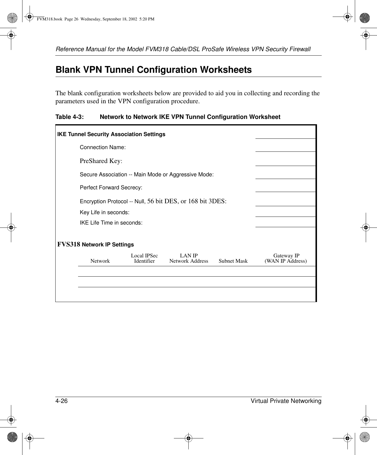
![About This Manual xiii Preface About This ManualThank your for purchasing the NETGEAR™ FVM318 Cable/DSL ProSafe Wireless VPN Security Firewall. This manual describes the features of the firewall and provides installation and configuration instructions.AudienceThis reference manual assumes that the reader has intermediate to advanced computer and Internet skills. However, basic computer network, Internet, firewall, and VPN technologies tutorial information is provided in the Appendices.Typographical ConventionsThis guide uses the following typographical conventions:italics Book titles and UNIX file, command, and directory names.courier font Screen text, user-typed command-line entries.Initial Caps Menu titles and window and button names.[Enter] Named keys in text are shown enclosed in square brackets. The notation [Enter] is used for the Enter key and the Return key.[Ctrl]+C Two or more keys that must be pressed simultaneously are shown in text linked with a plus (+) sign.ALL CAPS DOS file and directory names.FVM318.book Page xiii Wednesday, September 18, 2002 5:20 PM](https://usermanual.wiki/Netgear-orporated/FVM318.users-manual-1-of-2/User-Guide-293418-Page-14.png)


![Reference Manual for the Model FVM318 Cable/DSL ProSafe Wireless VPN Security FirewallVirtual Private Networking 4-25 The SPI should be a string of hexadecimal [0-9,A-F] characters, and should not be used in any other Security Association.Tip: For simplicity or troubleshooting, the Incoming and Outgoing SPI can be identical.4. For Encryption Protocol, select one:a. Null - Fastest, but no security. b. DES - Faster but less secure than 3DES. c. 3DES - (Triple DES) Most secure. 5. Enter a hexadecimal Encryption Key— For DES, enter 16 hexadecimal [0-9,A-F] characters. — For 3DES, enter 48 hexadecimal [0-9,A-F] characters. The encryption key must match exactly the key used by the remote router or host. 6. Select the Authentication Protocol— MD5 (default) - 128 bits, faster but less secure.— SHA-1 - 160 bits, slower but more secure.7. Enter 32 hexadecimal characters for the Authentication Key The authentication key must match exactly the key used by the remote router or host.8. Click the NETBIOS Enable check box to allow NETBIOS over the VPN tunnel.9. Click Apply to enter the SA into the table. FVM318.book Page 25 Wednesday, September 18, 2002 5:20 PM](https://usermanual.wiki/Netgear-orporated/FVM318.users-manual-1-of-2/User-Guide-293418-Page-80.png)