Netgear orporated FVM318 Wireless Router User Manual FVM318
Netgear Incorporated Wireless Router FVM318
Contents
- 1. users manual 1 of 2
- 2. users manual 2 of 2
users manual 1 of 2

SM-FVM318NA-0
October 2002
NETGEAR, Inc.
4500 Great America Parkway
Santa Clara, CA 95054 USA
Phone 1-888-NETGEAR
Reference Manual for the
Model FVM318 Cable/DSL
ProSafe Wireless VPN
Security Firewall
Reference Manual
FVM318.book Page i Wednesday, September 18, 2002 5:20 PM
FEDERAL COMMUNICATIONS COMMISSION
INTERFERENCE STATEMENT
This equipment has been tested and found to comply with the limits for a Class B
digital device, pursuant to Part 15 of the FCC Rules. These limits are designed
to provide reasonable protection against harmful interference in a residential
installation. This equipment generates, uses and can radiate radio frequency
energy and, if not installed and used in accordance with the instructions, may
cause harmful interference to radio communications. However, there is no
guarantee that interference will not occur in a particular installation. If this
equipment does cause harmful interference to radio or television reception,
which can be determined by turning the equipment off and on, the user is
encouraged to try to correct the interference by one or more of the following
measures:
-- Reorient or relocate the receiving antenna.
-- Increase the separation between the equipment and receiver.
-- Connect the equipment into an outlet on a circuit different from that to which
the receiver is connected.
-- Consult the dealer or an experienced radio/TV technician for help.
CAUTION:
Any changes or modifications not expressly approved by the grantee of this
device could void
the user's authority to operate the equipment.
FCC RF Radiation Exposure Statement
This equipment complies with FCC RF radiation exposure limits set forth for an
uncontrolled environment. This equipment should be installed and operated with
a minimum distance of 20cm between the radiator and your body.

ii
© 2002 by NETGEAR, Inc. All rights reserved.
Trademarks
NETGEAR and Auto Uplink are trademarks or registered trademarks of Netgear, Inc.
Microsoft, Windows, and Windows NT are registered trademarks of Microsoft Corporation.
Other brand and product names are registered trademarks or trademarks of their respective holders.
Statement of Conditions
In the interest of improving internal design, operational function, and/or reliability, NETGEAR reserves the right to
make changes to the products described in this document without notice.
NETGEAR does not assume any liability that may occur due to the use or application of the product(s) or circuit
layout(s) described herein.
Federal Communications Commission (FCC) Compliance Notice: Radio Frequency Notice
This equipment has been tested and found to comply with the limits for a Class B digital device, pursuant to
part 15 of the FCC Rules. These limits are designed to provide reasonable protection against harmful interference in a
residential installation. This equipment generates, uses, and can radiate radio frequency energy and, if not installed and
used in accordance with the instructions, may cause harmful interference to radio communications. However, there is no
guarantee that interference will not occur in a particular installation. If this equipment does cause harmful interference to
radio or television reception, which can be determined by turning the equipment off and on, the user is encouraged to try
to correct the interference by one or more of the following measures:
• Reorient or relocate the receiving antenna.
• Increase the separation between the equipment and receiver.
• Connect the equipment into an outlet on a circuit different from that to which the receiver is connected.
• Consult the dealer or an experienced radio/TV technician for help.
EN 55 022 Declaration of Conformance
This is to certify that the FVM318 Cable/DSL ProSafe Wireless VPN Security Firewall is shielded against the
generation of radio interference in accordance with the application of Council Directive 89/336/EEC, Article 4a.
Conformity is declared by the application of EN 55 022 Class B (CISPR 22).
FVM318.book Page ii Wednesday, September 18, 2002 5:20 PM

iii
Bestätigung des Herstellers/Importeurs
Es wird hiermit bestätigt, daß dasFVM318 Cable/DSL ProSafe Wireless VPN Security Firewall gemäß der im
BMPT-AmtsblVfg 243/1991 und Vfg 46/1992 aufgeführten Bestimmungen entstört ist. Das vorschriftsmäßige Betreiben
einiger Geräte (z.B. Testsender) kann jedoch gewissen Beschränkungen unterliegen. Lesen Sie dazu bitte die
Anmerkungen in der Betriebsanleitung.
Das Bundesamt für Zulassungen in der Telekommunikation wurde davon unterrichtet, daß dieses Gerät auf den Markt
gebracht wurde und es ist berechtigt, die Serie auf die Erfüllung der Vorschriften hin zu überprüfen.
Certificate of the Manufacturer/Importer
It is hereby certified that the FVM318 Cable/DSL ProSafe Wireless VPN Security Firewall has been suppressed
in accordance with the conditions set out in the BMPT-AmtsblVfg 243/1991 and Vfg 46/1992. The operation of some
equipment (for example, test transmitters) in accordance with the regulations may, however, be subject to certain
restrictions. Please refer to the notes in the operating instructions.
Federal Office for Telecommunications Approvals has been notified of the placing of this equipment on the market
and has been granted the right to test the series for compliance with the regulations.
Voluntary Control Council for Interference (VCCI) Statement
This equipment is in the second category (information equipment to be used in a residential area or an adjacent area
thereto) and conforms to the standards set by the Voluntary Control Council for Interference by Data Processing
Equipment and Electronic Office Machines aimed at preventing radio interference in such residential areas.
When used near a radio or TV receiver, it may become the cause of radio interference.
Read instructions for correct handling.
Technical Support
Refer to the Support Information Card that shipped with your FVM318 Cable/DSL ProSafe Wireless VPN Security
Firewall.
World Wide Web
NETGEAR maintains a World Wide Web home page that you can access at the universal resource locator (URL)
http://www.netgear.com. A direct connection to the Internet and a Web browser such as Internet Explorer
or Netscape are required.
FVM318.book Page iii Wednesday, September 18, 2002 5:20 PM

iv
FVM318.book Page iv Wednesday, September 18, 2002 5:20 PM

Contents v
Contents
Preface
About This Manual
Audience .......................................................................................................................1-xiii
Typographical Conventions ..........................................................................................1-xiii
Special Message Formats ........................................................................................... 1-xiv
Technical Support ........................................................................................................ 1-xiv
Chapter 1
Introduction
About the FVM318 ..........................................................................................................1-1
Key Features ..................................................................................................................1-1
A Powerful, True Firewall .........................................................................................1-1
Content Filtering .......................................................................................................1-2
Configurable Auto Uplink™ Ethernet Connection ....................................................1-2
Protocol Support ......................................................................................................1-2
Easy Installation and Management ..........................................................................1-3
What’s in the Box? ..........................................................................................................1-5
The Firewall’s Front Panel .................................................................................1-5
The Firewall’s Rear Panel ..................................................................................1-6
Chapter 2
Connecting the Firewall to the Internet
What You Will Need Before You Begin ...........................................................................2-1
LAN Hardware Requirements ..................................................................................2-1
Computer Requirements ....................................................................................2-1
Cable or DSL Modem Requirement ..................................................................2-1
LAN Configuration Requirements ............................................................................2-2
Internet Configuration Requirements .......................................................................2-2
Where Do I Get the Internet Configuration Parameters? ..................................2-2
Connecting the FVM318 firewall to Your LAN ................................................................2-4
Connecting the FVM318 firewall to the Internet .............................................................2-8
FVM318.book Page v Wednesday, September 18, 2002 5:20 PM

vi Contents
Using the Smart Wizard to Auto-Detect Your Internet Connection Type ..................2-8
Manually Configuring Your Internet Connection .....................................................2-14
Configuring Wireless Connectivity ................................................................................2-17
Testing Your Internet Connection ..................................................................................2-21
Chapter 3
Protecting Your Network
Protecting Access to Your FVM318 firewall ....................................................................3-1
Configuring Basic Firewall Services ...............................................................................3-3
Blocking Functions, Keywords, Sites, and Services ................................................3-3
Block Services ...................................................................................................3-5
Setting Times and Scheduling Firewall Services ............................................................3-7
Chapter 4
Virtual Private Networking
Network to Network and Remote Computer to Network VPNs ......................................4-1
Planning a VPN ..............................................................................................................4-2
VPN Configuration Choices ...............................................................................4-2
Sample Network to Network VPN Tunnel Configuration Worksheet .................4-3
Using the VPN Connection .............................................................................. 4-11
Configuring a Remote PC to Network VPN ..................................................................4-12
Sample PC to Network VPN Tunnel Configuration Worksheet .......................4-12
Check the VPN Connection .............................................................................4-21
Monitoring the PC to Network VPN Connection Using SafeNet Tools ............4-22
Deleting a Security Association ..............................................................................4-23
Manual Keying ..............................................................................................................4-24
Blank VPN Tunnel Configuration Worksheets ..............................................................4-26
Chapter 5
Managing Your Network
Network Management Information .................................................................................5-1
Viewing Router Status and Usage Statistics ............................................................5-1
Viewing Attached Devices ........................................................................................5-4
Viewing, Selecting, and Saving Logged Information ................................................5-5
Selecting What Information to Log ....................................................................5-6
Saving Log Files on a Server ............................................................................5-7
Examples of log messages ......................................................................................5-7
Activation and Administration ............................................................................5-7
FVM318.book Page vi Wednesday, September 18, 2002 5:20 PM

Contents vii
Dropped Packets ...............................................................................................5-7
Enabling Security Event E-mail Notification ...................................................................5-8
Backing Up, Restoring, or Erasing Your Settings ...........................................................5-9
Running Diagnostic Utilities and Rebooting the Router ................................................5-12
Enabling Remote Management ....................................................................................5-13
Upgrading the Router’s Firmware .................................................................................5-14
Chapter 6
Wireless Configuration
Considerations For A Wireless Network .........................................................................6-1
Security ....................................................................................................................6-1
Placement and Range ..............................................................................................6-1
Wireless Settings ............................................................................................................6-2
Wireless Network Settings .......................................................................................6-3
Using the Wireless Card Access List to Restrict Wireless Access by MAC Address 6-4
Configuring Wired Equivalent Privacy (WEP) ..........................................................6-5
Chapter 7
Advanced Configuration
Configuring Advanced Security ......................................................................................7-1
Setting Up A Default DMZ Server ............................................................................7-1
Respond to Ping on Internet WAN Port ...................................................................7-2
Configuring LAN IP Settings ...........................................................................................7-2
LAN TCP/IP Setup ...................................................................................................7-2
MTU Size .................................................................................................................7-3
DHCP .......................................................................................................................7-4
Use router as DHCP server ...............................................................................7-4
Reserved IP addresses .....................................................................................7-5
Configuring Dynamic DNS .......................................................................................7-6
Using Static Routes ........................................................................................................7-8
Static Route Example ...............................................................................................7-8
Chapter 8
Troubleshooting
Basic Functions ..............................................................................................................8-1
Power LED Not On ...................................................................................................8-2
Test LED Never Turns On or Test LED Stays On .....................................................8-2
Local or Internet Port Link LEDs Not On ..................................................................8-2
FVM318.book Page vii Wednesday, September 18, 2002 5:20 PM

viii Contents
Troubleshooting the Web Configuration Interface ..........................................................8-4
Troubleshooting the ISP Connection ..............................................................................8-5
Troubleshooting a TCP/IP Network Using a Ping Utility .................................................8-6
Testing the LAN Path to Your Firewall ......................................................................8-6
Testing the Path from Your PC to a Remote Device ................................................8-7
Restoring the Default Configuration and Password ........................................................8-8
Using the Default Reset button ................................................................................8-8
Problems with Date and Time .........................................................................................8-9
Appendix A
Technical Specifications
Appendix B
Network, Routing, Firewall, and Wireless Basics
Related Publications ...................................................................................................... B-1
Basic Router Concepts .................................................................................................. B-1
What is a Router? ................................................................................................... B-2
Routing Information Protocol ................................................................................... B-2
IP Addresses and the Internet ................................................................................. B-2
Netmask .................................................................................................................. B-4
Subnet Addressing .................................................................................................. B-5
Private IP Addresses ............................................................................................... B-7
Single IP Address Operation Using NAT ................................................................. B-8
MAC Addresses and Address Resolution Protocol ................................................. B-9
Related Documents ................................................................................................. B-9
Domain Name Server ............................................................................................ B-10
IP Configuration by DHCP .................................................................................... B-10
Ethernet Cabling ...........................................................................................................B-11
Uplink Switches and Crossover Cables .................................................................B-11
Cable Quality ......................................................................................................... B-12
Internet Security and Firewalls .................................................................................... B-12
What is a Firewall? ................................................................................................ B-12
Stateful Packet Inspection ..................................................................................... B-13
Denial of Service Attack ........................................................................................ B-13
Wireless Networking .................................................................................................... B-13
Wireless Network Configuration ............................................................................ B-13
Ad-hoc Mode (Peer-to-Peer Workgroup) ........................................................ B-14
FVM318.book Page viii Wednesday, September 18, 2002 5:20 PM

Contents ix
Infrastructure Mode ........................................................................................ B-14
Extended Service Set Identification (ESSID) ........................................................ B-14
Authentication and WEP Encryption ..................................................................... B-15
Wireless Channel Selection .................................................................................. B-15
Ethernet Cabling .......................................................................................................... B-17
Uplink Switches, Crossover Cables, and MDI/MDIX Switching ............................ B-17
Cable Quality ......................................................................................................... B-18
Appendix C
Preparing Your Network
Preparing Your Computers for TCP/IP Networking ....................................................... C-1
Configuring Windows 95, 98, and ME for TCP/IP Networking ................................ C-2
Install or Verify Windows Networking Components .......................................... C-2
Enabling DHCP to Automatically Configure TCP/IP Settings ........................... C-4
Selecting Windows’ Internet Access Method .................................................... C-4
Verifying TCP/IP Properties .............................................................................. C-5
Configuring Windows NT, 2000 or XP for IP Networking ........................................ C-5
Install or Verify Windows Networking Components .......................................... C-5
Verifying TCP/IP Properties .............................................................................. C-6
Configuring the Macintosh for TCP/IP Networking .................................................. C-6
MacOS 8.6 or 9.x .............................................................................................. C-6
MacOS X .......................................................................................................... C-7
Verifying TCP/IP Properties for Macintosh Computers ..................................... C-8
Verifying the Readiness of Your Internet Account ......................................................... C-9
Are Login Protocols Used? ..................................................................................... C-9
What Is Your Configuration Information? ................................................................ C-9
Obtaining ISP Configuration Information for Windows Computers ................. C-10
Obtaining ISP Configuration Information for Macintosh Computers ............... C-11
Restarting the Network ................................................................................................ C-12
Glossary
Index
FVM318.book Page ix Wednesday, September 18, 2002 5:20 PM

xContents
FVM318.book Page x Wednesday, September 18, 2002 5:20 PM

xi
List of Procedures
Procedure 2-1: Record Your Internet Connection Information ......................................2-3
Procedure 2-2: Connecting the Firewall to Your LAN ....................................................2-4
Procedure 2-3: Auto-Detecting Your Internet Connection Type ....................................2-9
Procedure 2-4: Wizard-Detected Login Account Setup ...............................................2-10
Procedure 2-5: Wizard-Detected Dynamic IP Account Setup .....................................2-11
Procedure 2-6: Wizard-Detected Fixed IP (Static) Account Setup ..............................2-13
Procedure 2-7: Manual Configuration .........................................................................2-14
Procedure 2-8: Serial Port Internet Connection Configuration ....................................2-17
Procedure 3-1: Changing the Built-In Password ...........................................................3-2
Procedure 3-1: Changing the Administrator Login Timeout ..........................................3-3
Procedure 3-2: Block Functions, Keywords, and Sites .................................................3-4
Procedure 3-3: Block Services ......................................................................................3-6
Procedure 3-4: Setting Your Time Zone ........................................................................3-7
Procedure 3-5: Scheduling Firewall Services ................................................................3-9
Procedure 4-1: Configuring a Network to Network VPN Tunnel ....................................4-4
Procedure 4-2: Check the VPN Connection ................................................................ 4-11
Procedure 4-3: Configuring a Remote PC to Network VPN ........................................4-13
Procedure 4-4: Using Manual Keying as an Alternative to IKE ...................................4-24
Procedure 5-5: Backup the Configuration to a File .......................................................5-9
Procedure 5-6: Restore a Configuration from a File ....................................................5-11
Procedure 5-7: Erase the Configuration ......................................................................5-11
Procedure 5-8: Configure Remote Management ........................................................5-13
Procedure 5-1: Router Upgrade ..................................................................................5-14
Procedure 7-1: Configure LAN TCP/IP Setup ...............................................................7-6
Procedure 7-2: Configure Dynamic DNS ......................................................................7-7
Procedure 7-3: Configuring Static Routes .....................................................................7-9
FVM318.book Page xi Wednesday, September 18, 2002 5:20 PM

xii
FVM318.book Page xii Wednesday, September 18, 2002 5:20 PM

About This Manual xiii
Preface
About This Manual
Thank your for purchasing the NETGEAR™ FVM318 Cable/DSL ProSafe Wireless VPN Security
Firewall.
This manual describes the features of the firewall and provides installation and configuration
instructions.
Audience
This reference manual assumes that the reader has intermediate to advanced computer and Internet
skills. However, basic computer network, Internet, firewall, and VPN technologies tutorial
information is provided in the Appendices.
Typographical Conventions
This guide uses the following typographical conventions:
italics Book titles and UNIX file, command, and directory names.
courier font Screen text, user-typed command-line entries.
Initial Caps Menu titles and window and button names.
[Enter] Named keys in text are shown enclosed in square brackets. The notation
[Enter] is used for the Enter key and the Return key.
[Ctrl]+C Two or more keys that must be pressed simultaneously are shown in text
linked with a plus (+) sign.
ALL CAPS DOS file and directory names.
FVM318.book Page xiii Wednesday, September 18, 2002 5:20 PM
Reference Manual for the Model FVM318 Cable/DSL ProSafe Wireless VPN Security Firewall
xiv About This Manual
Special Message Formats
This guide uses the following formats to highlight special messages:
Technical Support
For help with any technical issues, contact Customer Support at 1-888-NETGEAR, or visit us on
the Web at www.NETGEAR.com. The NETGEAR Web site includes an extensive knowledge
base, answers to frequently asked questions, and a means for submitting technical questions
online.
Note: This format is used to highlight information of importance or special interest.
Procedure: This format is used to let you know that you are following a sequence of
steps required to complete a task.
Warning: This format is used to highlight information about the possibility of injury or
equipment damage.
Danger: This format is used to alert you that there is the potential for incurring an
electrical shock if you mishandle the equipment.
FVM318.book Page xiv Wednesday, September 18, 2002 5:20 PM

Reference Manual for the Model FVM318 Cable/DSL ProSafe Wireless VPN Security Firewall
About This Manual xv
FVM318.book Page xv Wednesday, September 18, 2002 5:20 PM
FVM318.book Page xvi Wednesday, September 18, 2002 5:20 PM

Introduction 1-1
Chapter 1
Introduction
This chapter describes the features of the NETGEAR FVM318 Cable/DSL ProSafe Wireless VPN
Security Firewall.
About the FVM318
The FVM318 is a complete security solution that protects your network from attacks and
intrusions. Unlike simple Internet sharing routers that rely on Network Address Translation (NAT)
for security, the FVM318 uses Stateful Packet Inspection for Denial of Service (DoS) attack
protection and intrusion detection. The 8-port FVM318 with auto fail-over connectivity through
the serial port provides highly reliable Internet access for up to 253 users.
Key Features
The FVM318 offers the following features.
A Powerful, True Firewall
Unlike simple Internet sharing NAT routers, the FVM318 is a true firewall, using stateful packet
inspection to defend against hacker attacks. Its firewall features include:
• Denial of Service (DoS) protection
Automatically detects and thwarts Denial of Service (DoS) attacks such as Ping of Death,
SYN Flood, LAND Attack and IP Spoofing.
• Blocks unwanted traffic from the Internet to your LAN.
• Blocks access from your LAN to Internet locations or services that you specify as off-limits.
FVM318.book Page 1 Wednesday, September 18, 2002 5:20 PM

Reference Manual for the Model FVM318 Cable/DSL ProSafe Wireless VPN Security Firewall
1-2 Introduction
• Logs security incidents
The FVM318 will log security events such as blocked incoming traffic, port scans, attacks,
and administrator logins. You can configure the firewall to email the log to you at specified
intervals. You can also configure the firewall to send immediate alert messages to your email
address or email pager whenever a significant event occurs.
Content Filtering
With its content filtering feature, the FVM318 prevents objectionable content from reaching your
PCs. The firewall allows you to control access to Internet content by screening for keywords
within Web addresses. You can configure the firewall to log and report attempts to access
objectionable Internet sites.
Configurable Auto Uplink™ Ethernet Connection
With its internal 8-port 10/100 switch, the FVM318 can connect to either a 10 Mbps standard
Ethernet network or a 100 Mbps Fast Ethernet network. Both the local LAN and the Internet WAN
interfaces are autosensing and capable of full-duplex or half-duplex operation.
The firewall incorporates Auto UplinkTM technology. Each LOCAL Ethernet port will
automatically sense whether the Ethernet cable plugged into the port should have a ‘normal’
connection such as to a PC or an ‘uplink’ connection such as to a switch or hub. That port will then
configure itself to the correct configuration. This feature also eliminates the need to worry about
crossover cables, as Auto Uplink will accommodate either type of cable to make the right
connection.
Protocol Support
The FVM318 supports the Transmission Control Protocol/Internet Protocol (TCP/IP) and Routing
Information Protocol (RIP). Appendix B, “Network, Routing, Firewall, and Wireless Basics”
provides further information on TCP/IP.
• IP Address Sharing by NAT
The FVM318 allows several networked PCs to share an Internet account using only a single IP
address, which may be statically or dynamically assigned by your Internet service provider
(ISP). This technique, known as Network Address Translation (NAT), allows the use of an
inexpensive single-user ISP account.
FVM318.book Page 2 Wednesday, September 18, 2002 5:20 PM

Reference Manual for the Model FVM318 Cable/DSL ProSafe Wireless VPN Security Firewall
Introduction 1-3
• Automatic Configuration of Attached PCs by DHCP
The FVM318 dynamically assigns network configuration information, including IP, gateway,
and domain name server (DNS) addresses, to attached PCs on the LAN using the Dynamic
Host Configuration Protocol (DHCP). This feature greatly simplifies configuration of PCs on
your local network.
• DNS Proxy
When DHCP is enabled and no DNS addresses are specified, the firewall provides its own
address as a DNS server to the attached PCs. The firewall obtains actual DNS addresses from
the ISP during connection setup and forwards DNS requests from the LAN.
• PPP over Ethernet (PPPoE)
PPP over Ethernet is a protocol for connecting remote hosts to the Internet over a DSL
connection by simulating a dial-up connection. This feature eliminates the need to run a login
program such as EnterNet or WinPOET on your PC.
• PPTP login support for European ISPs, BigPond login for Telstra cable in Australia.
•Dynamic DNS
Dynamic DNS services allow remote users to find your network using a domain name when
your IP address is not permanently assigned. The firewall contains a client that can connect to
many popular Dynamic DNS services to register your dynamic IP address.
Easy Installation and Management
You can install, configure, and operate the FVM318 within minutes after connecting it to the
network. The following features simplify installation and management tasks:
• Browser-based management
Browser-based configuration allows you to easily configure your firewall from almost any
type of personal computer, such as Windows, Macintosh, or Linux. A user-friendly Setup
Wizard is provided and online help documentation is built into the browser-based Web
Management Interface.
• Smart Wizard
The firewall automatically senses the type of Internet connection, asking you only for the
information required for your type of ISP account.
• Auto fail-over connectivity through an analog or ISDN modem connected to the serial port
If the cable or DSL modem Internet connection fails, after a waiting for an amount of time you
specify, the FVM318 can automatically establish a backup ISDN or dial-up Internet
connection via the serial port on the firewall.
FVM318.book Page 3 Wednesday, September 18, 2002 5:20 PM

Reference Manual for the Model FVM318 Cable/DSL ProSafe Wireless VPN Security Firewall
1-4 Introduction
• Remote management
The firewall allows you to login to the Web Management Interface from a remote location via
the Internet. For security, you can limit remote management access to a specified remote IP
address or range of addresses, and you can choose a nonstandard port number.
• Remote Access Server connectivity vial the serial port
• Diagnostic functions
The firewall incorporates built-in diagnostic functions such as Ping, DNS lookup, and remote
reboot. These functions allow you to test Internet connectivity and reboot the firewall. You can
use these diagnostic functions directly from the FVM318 when your are connect on the LAN
or when you are connected over the Internet via the remote management function.
• Visual monitoring
The firewall’s front panel LEDs provide an easy way to monitor its status and activity.
• Flash EPROM for firmware upgrade
• Regional support, including ISPs like Telstra DSL and BigPond or Deutsche Telekom.
FVM318.book Page 4 Wednesday, September 18, 2002 5:20 PM
Reference Manual for the Model FVM318 Cable/DSL ProSafe Wireless VPN Security Firewall
Introduction 1-5
What’s in the Box?
The product package should contain the following items:
• FVM318 Cable/DSL ProSafe Wireless VPN Security Firewall
• AC power adapter
• Category 5 (CAT5) Ethernet cable
•FVM318 Resource CD, including:
— This manual
— Application Notes, Tools, and other helpful information
• Warranty and registration card
• Support information card
If any of the parts are incorrect, missing, or damaged, contact your NETGEAR dealer. Keep the
carton, including the original packing materials, in case you need to return the product for repair.
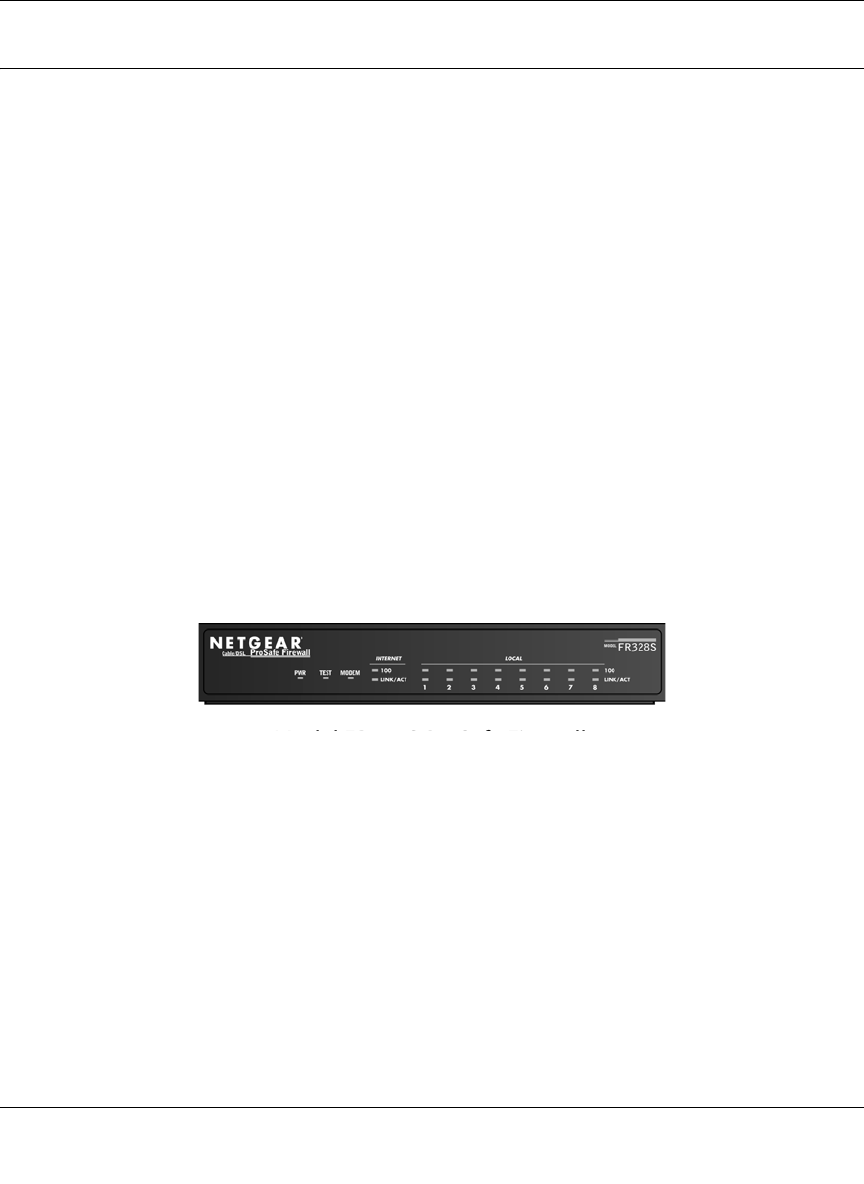
The Firewall’s Front Panel
The front panel of the FVM318 (Figure 1-1) contains status LEDs.
Figure 1-1: FVM318 Front Panel
You can use some of the LEDs to verify connections. Table 1-1 lists and describes each LED on
the front panel of the firewall.
FVM318.book Page 5 Wednesday, September 18, 2002 5:20 PM
Reference Manual for the Model FVM318 Cable/DSL ProSafe Wireless VPN Security Firewall
1-6 Introduction
These LEDs are green when lit, except for the TEST LED, which is amber.
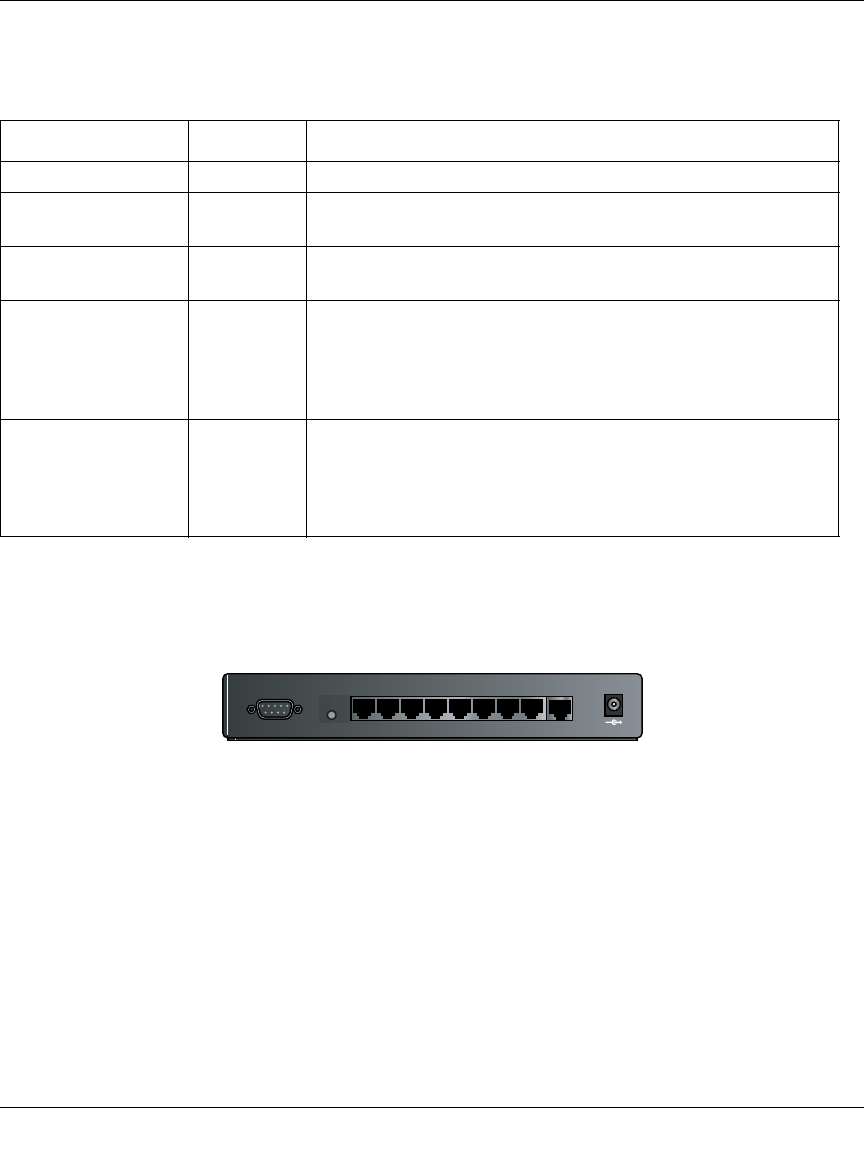
The Firewall’s Rear Panel
The rear panel of the FVM318 (Figure 1-2) contains the connections identified below.
Figure 1-2: FVM318 Rear Panel
Viewed from left to right, the rear panel contains the following elements:
• DB-9 serial port for modem connection
• Factory Default Reset push button
• Eight Local Ethernet RJ-45 ports for connecting the firewall to the local computers
• Internet WAN Ethernet RJ-45 port for connecting the firewall to a cable or DSL modem
• AC power adapter input
Table 1-1: LED Descriptions
Label Activity Description
POWER On Power is supplied to the firewall.
TEST On
Off The system is initializing.
The system is ready and running.
MODEM On/Blinking The port detected a link with the Internet WAN connection or
Remote Access Server. Blinking indicates data transmission.
INTERNET
100 On/Blinking The Internet port is operating at 100 Mbps.
LINK/ACT (Activity) On/Blinking The port detected a link with the Internet WAN connection and is
operating at 10 Mbps. Blinking indicates data transmission.
LOCAL
100 On/Blinking The Local port is operating at 100 Mbps.
LINK/ACT
(Link/Activity) On/Blinking The Local port has detected a link with a LAN connection and is
operating at 10 Mbps. Blinking indicates data transmission.
MODEM 12VDC O.5A
87654321
LO CA L
10/100M
IN TERN ET
FVM318.book Page 6 Wednesday, September 18, 2002 5:20 PM

Connecting the Firewall to the Internet 2-1
Chapter 2
Connecting the Firewall to the Internet
This chapter describes how to set up the firewall on your Local Area Network (LAN), connect to
the Internet, perform basic configuration of your FVM318 Cable/DSL ProSafe Wireless VPN
Security Firewall using the Setup Wizard, or how to manually configure your Internet connection.
What You Will Need Before You Begin
You need to prepare these three things before you can connect your firewall to the Internet:
1. A computer properly connected to the firewall as explained below.
2. Active Internet service such as that provided by a DSL or Cable modem account.
3. The Internet Service Provider (ISP) configuration information for your DSL or Cable modem
account.
LAN Hardware Requirements
The FVM318 firewall connects to your LAN via twisted-pair Ethernet cables.
Computer Requirements
To use the FVM318 firewall on your network, each computer must have an installed Ethernet
Network Interface Card (NIC) and an Ethernet cable. If the computer will connect to your network
at 100 Mbps, you must use a Category 5 (CAT5) cable such as the one provided with your firewall.
Cable or DSL Modem Requirement
The cable modem or DSL modem must provide a standard 10 Mbps 10BASE-T or 100 Mbps
100BASE-T Ethernet interface.
FVM318.book Page 1 Wednesday, September 18, 2002 5:20 PM

Reference Manual for the Model FVM318 Cable/DSL ProSafe Wireless VPN Security Firewall
2-2 Connecting the Firewall to the Internet
LAN Configuration Requirements
For the initial connection to the Internet and configuration of your firewall, you will need to
connect a computer to the firewall which is set to automatically get its TCP/IP configuration from
the firewall via DHCP.
Note: Please refer to Appendix C, "Preparing Your Network" for assistance with DHCP
configuration.
Internet Configuration Requirements
Depending on how your ISP set up your Internet account, you will need one or more of these
configuration parameters to connect your firewall to the Internet:
• Host and Domain Names
• ISP Login Name and Password
• ISP Domain Name Server (DNS) Addresses
• Fixed or Static IP Address
Where Do I Get the Internet Configuration Parameters?
There are several ways you can gather the required Internet connection information.
• Your ISP should have provided you with all the information needed to connect to the Internet.
If you cannot locate this information, you can ask your ISP to provide it or you can try one of
the options below.
• If you have a computer already connected using the active Internet access account, you can
gather the configuration information from that computer.
• For Windows 95/98/ME, open the Network control panel, select the TCP/IP entry for the
Ethernet adapter, and click Properties.
• For Windows 2000/XP, open the Local Area Network Connection, select the TCP/IP entry
for the Ethernet adapter, and click Properties.
• For Macintosh computers, open the TCP/IP or Network control panel.
• You may also refer to the FR328S Resource CD for the NETGEAR Router ISP Guide which
provides Internet connection information for many ISPs.
Once you locate your Internet configuration parameters, you may want to record them on the page
below according to the instructions in “Record Your Internet Connection Information” on
page 2-3.
FVM318.book Page 2 Wednesday, September 18, 2002 5:20 PM

Reference Manual for the Model FVM318 Cable/DSL ProSafe Wireless VPN Security Firewall
Connecting the Firewall to the Internet 2-3
Procedure 2-1: Record Your Internet Connection Information
1. Print this page. Fill in the configuration parameters from your Internet Service Provider (ISP).
ISP Login Name: The login name and password are case sensitive and must be entered exactly as
given by your ISP. Some ISPs use your full e-mail address as the login name. The Service Name is
not required by all ISPs. If you connect using a login name and password, then fill in the
following:
Login Name: ______________________________ Password: ____________________________
Service Name: _____________________________
Fixed or Static IP Address: If you have a static IP address, record the following information. For
example, 169.254.141.148 could be a valid IP address.
Fixed or Static Internet IP Address: ______ . ______ . ______ . ______
Subnet Mask: ______ . ______ . ______ . ______
Gateway IP Address: ______ . ______ . ______ . ______
ISP DNS Server Addresses: If you were given DNS server addresses, fill in the following:
Primary DNS Server IP Address: ______ . ______ . ______ . ______
Secondary DNS Server IP Address: ______ . ______ . ______ . ______
Host and Domain Names: Some ISPs use a specific host or domain name like CCA7324-A or
home. If you haven’t been given host or domain names, you can use the following examples as a
guide:
• If your main e-mail account with your ISP is aaa@yyy.com, then use aaa as your host name.
Your ISP might call this your account, user, host, computer, or system name.
• If your ISP’s mail server is mail.xxx.yyy.com, then use xxx.yyy.com as the domain name.
ISP Host Name: _________________________ ISP Domain Name: _______________________
For Serial Port Internet Access: If you use a dial-up account, record the following:
Account/User Name: _________________________ Password: _________________________
Telephone number: ______________________ Alternative number: ______________________
FVM318.book Page 3 Wednesday, September 18, 2002 5:20 PM

Reference Manual for the Model FVM318 Cable/DSL ProSafe Wireless VPN Security Firewall
2-4 Connecting the Firewall to the Internet
Connecting the FVM318 firewall to Your LAN
This section provides instructions for connecting the FVM318 Cable/DSL ProSafe Wireless VPN
Security Firewall to your Local Area Network (LAN).
Note: The Resource CD included with your firewall contains an animated Installation Assistant to
help you through this procedure.
Procedure 2-2: Connecting the Firewall to Your LAN
There are three steps to connecting your firewall:
1. Connect the firewall to your network
2. Log in to the firewall
3. Connect to the Internet
Follow the steps below to connect your firewall to your network. You can also refer to the
Resource CD included with your firewall which contains an animated Installation Assistant to help
you through this procedure.
1. Connect the Firewall
a. Turn off your computer and Cable or DSL Modem.
FVM318.book Page 4 Wednesday, September 18, 2002 5:20 PM
Reference Manual for the Model FVM318 Cable/DSL ProSafe Wireless VPN Security Firewall
Connecting the Firewall to the Internet 2-5
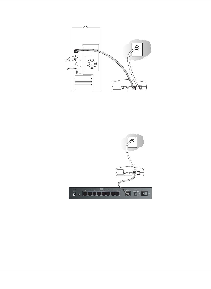
b. Disconnect the Ethernet cable (A) from your computer which connects to your Cable or
DSL modem.
Figure 2-1: Disconnect the Cable or DSL Modem
c. Connect the Ethernet cable (A) from your Cable or DSL modem to the FR328S’s Internet
port.
Figure 2-2: Connect the Cable or DSL Modem to the firewall
DSL modem
A
Cable or
DSL modem
A
FVM318.book Page 5 Wednesday, September 18, 2002 5:20 PM
Reference Manual for the Model FVM318 Cable/DSL ProSafe Wireless VPN Security Firewall
2-6 Connecting the Firewall to the Internet
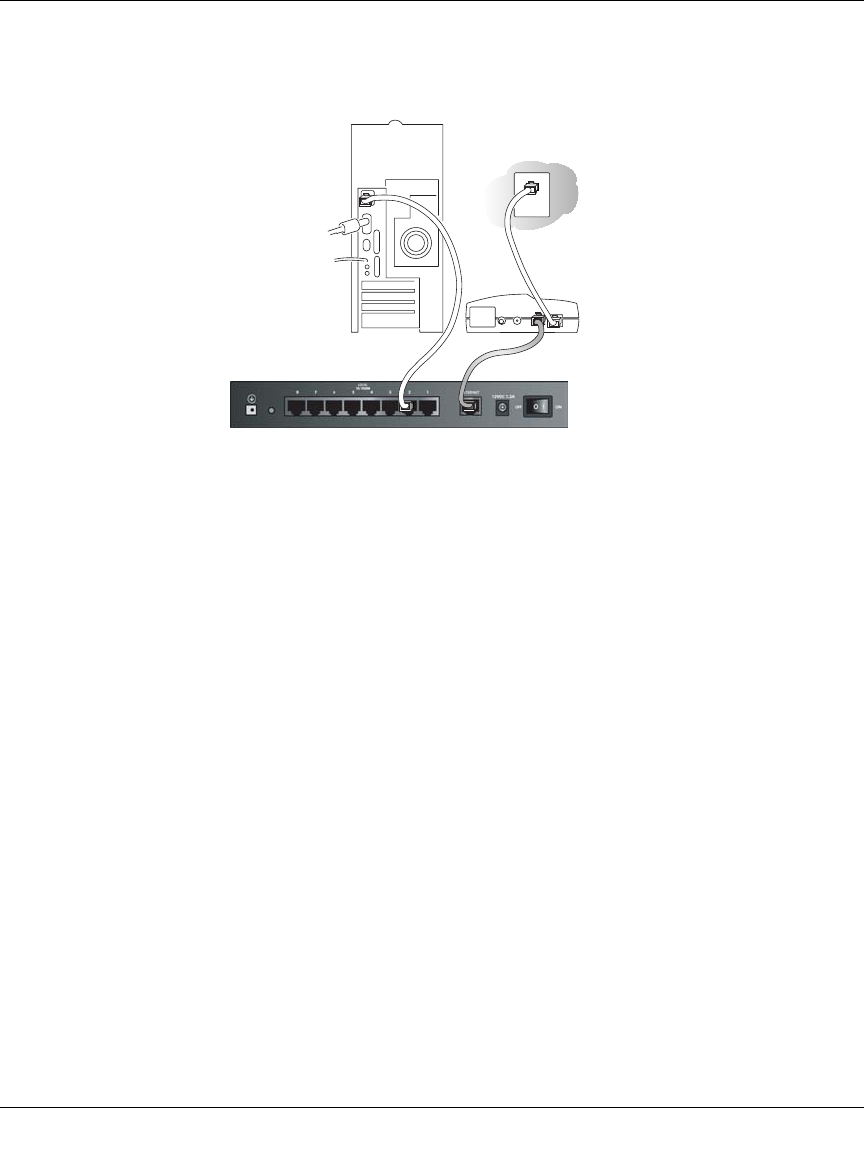
d. Connect the Ethernet cable (B) which came with the firewall from a Local port on the
router to your computer.
Figure 2-3: Connect the computers on your network to the firewall
Note: The FVM318 firewall incorporates Auto UplinkTM technology. Each LAN Ethernet port
will automatically sense whether the cable plugged into the port should have a 'normal'
connection (e.g. connecting to a PC) or an 'uplink' connection (e.g. connecting to a switch or
hub). That port will then configure itself to the correct configuration. This feature also
eliminates the need to worry about crossover cables, as Auto Uplink will accommodate either
type of cable to make the right connection.
e. Turn on the Cable or DSL modem and wait about 30 seconds for the lights to stop
blinking.
2. Log in to the Firewall
Note: To connect to the firewall, your computer needs to be configured to obtain an IP address
automatically via DHCP. Please refer to Appendix C, "Preparing Your Network" for
instructions on how to do this.
a. Turn on the firewall and wait for the Test light to stop blinking.
b. Now, turn on your computer.
Note: If you usually run software to log in to your Internet connection, do not run that
software.
FVS318 C bl /DSL P S f VPN Fi ll
Cable or
DSL modem
BA
FVM318.book Page 6 Wednesday, September 18, 2002 5:20 PM
Reference Manual for the Model FVM318 Cable/DSL ProSafe Wireless VPN Security Firewall
Connecting the Firewall to the Internet 2-7
Now that the Cable or DSL Modem, firewall, and the computer are turned on, verify the
following:
• When power on the firewall was first turned on, the PWR light went on, the TEST light
turned on within a few seconds, and then went off after approximately 10 seconds.
• The firewall’s LOCAL LINK/ACT lights are lit for any computers that are connected to it.
• The firewall’s INTERNET LINK light is lit, indicating a link has been established to the
cable or DSL modem.
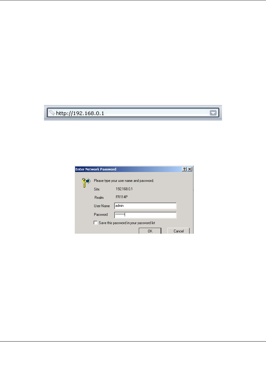
c. Next, use a browser like Internet Explorer or Netscape to log in to the firewall at its default
address of http://192.168.0.1.
Figure 2-4: Log in to the firewall
A login window opens as shown in Figure 2-5 below:
Figure 2-5: Login window
d. For security reasons, the firewall has its own user name and password. When prompted,
enter admin for the firewall User Name and password for the firewall Password, both in
lower case letters.
Note: The user name and password are not the same as any user name or password you
may use to log in to your Internet connection.
FVM318.book Page 7 Wednesday, September 18, 2002 5:20 PM
Reference Manual for the Model FVM318 Cable/DSL ProSafe Wireless VPN Security Firewall
2-8 Connecting the Firewall to the Internet
3. Connect to the Internet
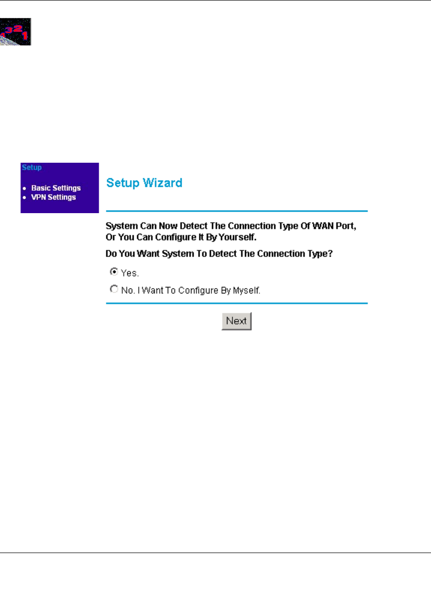
Figure 2-6: Setup Wizard
a. You are now connected to the firewall. If you do not see the menu above, click the Setup
Wizard link on the upper left of the main menu. Click the Yes button in the Setup Wizard.
b. Please click Next to follow the steps in the Setup Wizard to input the configuration
parameters from your ISP to connect to the Internet.
Note: If you were unable to connect to the firewall, please refer to “Basic Functions” on page 8-1.
Connecting the FVM318 firewall to the Internet
The firewall is now properly attached to your network. You are now ready to configure your
firewall to connect to the Internet. There are two ways you can configure your firewall to connect
to the Internet:
• Let the FVM318 auto-detect the type of Internet connection you have and configure it.
• Manually choose which type of Internet connection you have and configure it.
These options are described below. In either case, unless your ISP automatically assigns your
configuration automatically via DHCP, you will need the configuration parameters from your ISP
you recorded in “Record Your Internet Connection Information” on page 2-3.
Using the Smart Wizard to Auto-Detect Your Internet Connection
Type
Follow the procedures below to let the Smart Wizard help set up your Internet configuration.
FVM318.book Page 8 Wednesday, September 18, 2002 5:20 PM
Reference Manual for the Model FVM318 Cable/DSL ProSafe Wireless VPN Security Firewall
Connecting the Firewall to the Internet 2-9
Procedure 2-3: Auto-Detecting Your Internet Connection Type
The Web Configuration Manager built in to the firewall contains a Setup Wizard that can
automatically determine your network connection type.
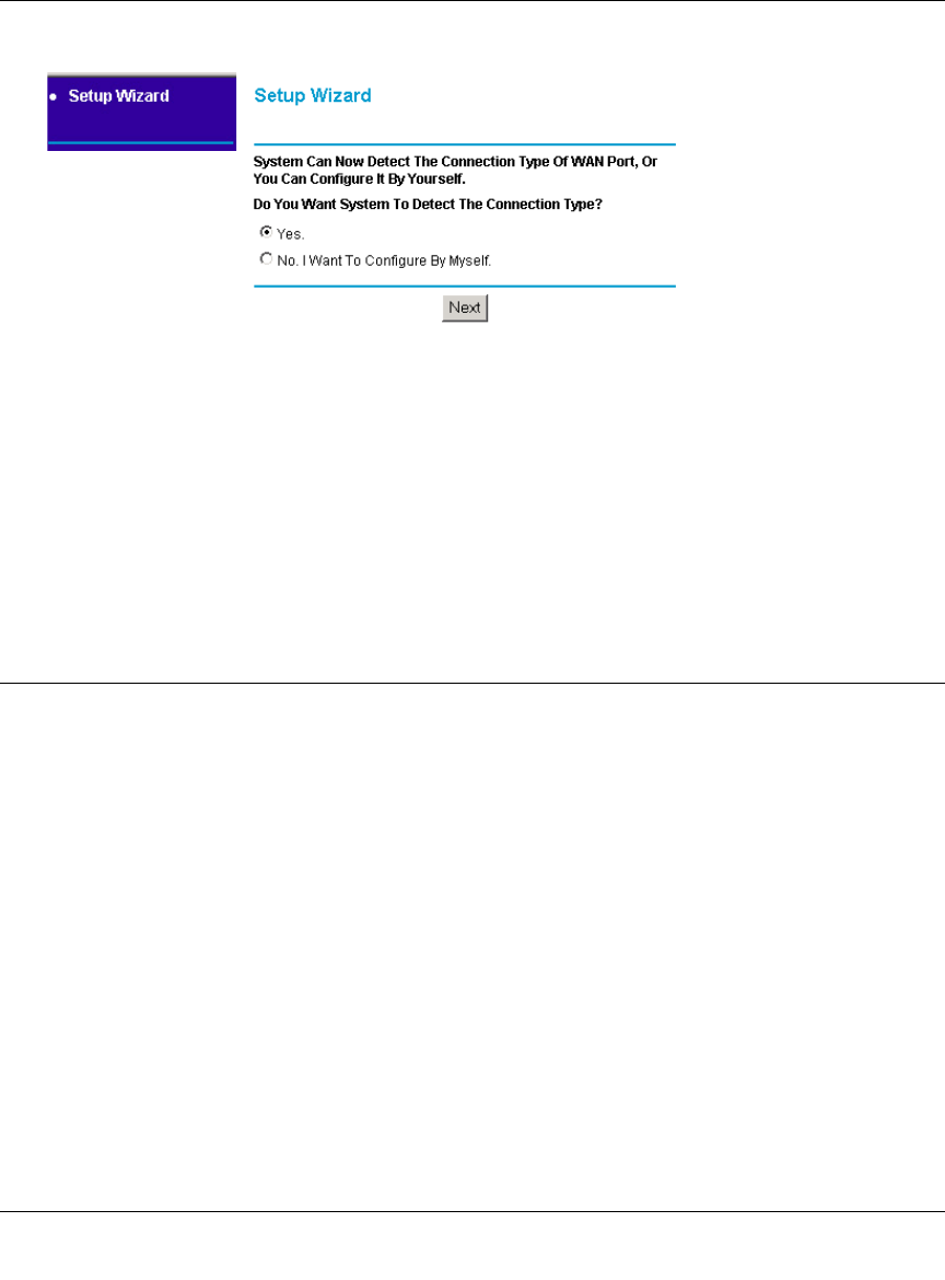
1. If your firewall has not yet been configured, the Setup Wizard shown in Figure 2-7 should
launch automatically.
When the Wizard launches, select Yes in the menu below to allow the firewall to automatically
determine your connection.
Figure 2-7: Built-in Web-based Configuration Manager Setup Wizard
Note: If, instead of the Setup Wizard menu, the main menu of the firewall’s Configuration
Manager as shown in Figure 2-13 appears, click the Setup Wizard link in the upper left to
bring up this menu.
2. Click Next
The Setup Wizard will now check for the following connection types:
• Dynamic IP assignment
• A login protocol such as PPPoE
• Fixed IP address assignment
FVM318.book Page 9 Wednesday, September 18, 2002 5:20 PM
Reference Manual for the Model FVM318 Cable/DSL ProSafe Wireless VPN Security Firewall
2-10 Connecting the Firewall to the Internet
Next, the Setup Wizard will report which connection type it has discovered, and then display
the appropriate configuration menu. If the Setup Wizard finds no connection, you will be
prompted to check the physical connection between your firewall and the cable or DSL
modem. When the connection is properly made, the firewall’s Internet LED should be on.
The procedures for filling in the configuration menu for each type of connection follow below.
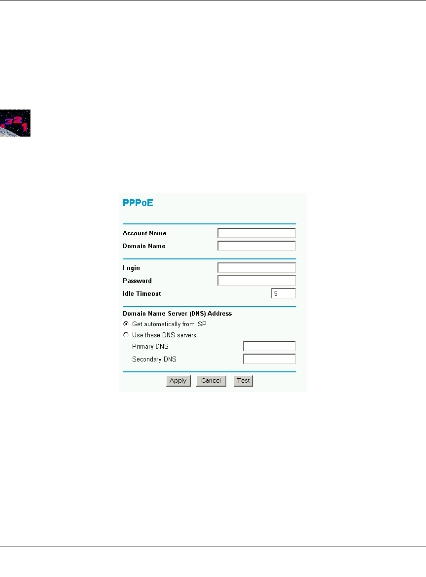
Procedure 2-4: Wizard-Detected Login Account Setup
If the Setup Wizard determines that your Internet service account uses a login protocol such as
PPP over Ethernet (PPPoE), you will be directed to a menu like the PPPoE menu in Figure 2-8:
Figure 2-8: Setup Wizard menu for PPPoE login accounts
1. Enter your Account Name (may also be called Host Name) and Domain Name. These
parameters may be necessary to access your ISP’s services such as mail or news servers. If you
leave the Domain Name field blank, the firewall will attempt to learn the domain
automatically from the ISP. If this is not successful, you may need to enter it manually.
2. Enter the PPPoE login user name and password provided by your ISP. These fields are case
sensitive. If you wish to change the login timeout, enter a new value in minutes.
FVM318.book Page 10 Wednesday, September 18, 2002 5:20 PM
Reference Manual for the Model FVM318 Cable/DSL ProSafe Wireless VPN Security Firewall
Connecting the Firewall to the Internet 2-11
Note: You will no longer need to launch the ISP’s login program on your PC in order to access
the Internet. When you start an Internet application, your firewall will automatically log you
in.
3. Domain Name Server (DNS) Address: If you know that your ISP does not automatically
transmit DNS addresses to the firewall during login, select “Use these DNS servers” and enter
the IP address of your ISP’s Primary DNS Server. If a Secondary DNS Server address is
available, enter it also.
If you enter an address here, after you finish configuring the firewall, reboot your PCs so
that the settings take effect.
4. Click on Apply to save your settings.
5. Click on the Test button to test your Internet connection. If the NETGEAR website does not
appear within one minute, refer to Chapter 8, Troubleshooting”.
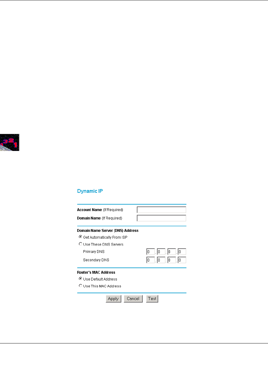
Procedure 2-5: Wizard-Detected Dynamic IP Account Setup
If the Setup Wizard determines that your Internet service account uses Dynamic IP assignment,
you will be directed to the menu shown in Figure 2-9 below:
Figure 2-9: Setup Wizard menu for Dynamic IP address
FVM318.book Page 11 Wednesday, September 18, 2002 5:20 PM

Reference Manual for the Model FVM318 Cable/DSL ProSafe Wireless VPN Security Firewall
2-12 Connecting the Firewall to the Internet
1. Enter your Account Name (may also be called Host Name) and Domain Name. These
parameters may be necessary to access your ISP’s services such as mail or news servers. If you
leave the Domain Name field blank, the firewall will attempt to learn the domain
automatically from the ISP. If this is not successful, you may need to enter it manually.
2. If you know that your ISP does not automatically transmit DNS addresses to the firewall
during login, select “Use these DNS servers” and enter the IP address of your ISP’s Primary
DNS Server. If a Secondary DNS Server address is available, enter it also.
A DNS server is a host on the Internet that translates Internet names (such as
www.netgear.com) to numeric IP addresses. Typically your ISP transfers the IP address of
one or two DNS servers to your firewall during login. If the ISP does not transfer an
address, you must obtain it from the ISP and enter it manually here. If you enter an address
here, you should reboot your PCs after configuring the firewall.
3. The Router’s MAC Address is the Ethernet MAC address that will be used by the firewall on
the Internet port.
If your ISP allows access from only one specific computer’s Ethernet MAC address, select
“Use this MAC address.” The firewall will then capture and use the MAC address of the
computer that you are now using. You must be using the one computer that is allowed by the
ISP. Otherwise, you can type in a MAC address.
Note: Some ISPs will register the Ethernet MAC address of the network interface card in
your PC when your account is first opened. They will then only accept traffic from the
MAC address of that PC. This feature allows your firewall to masquerade as that PC by
using its MAC address.
4. Click on Apply to save your settings.
5. Click on the Test button to test your Internet connection. If the NETGEAR website does not
appear within one minute, refer to Chapter 8, Troubleshooting”.
FVM318.book Page 12 Wednesday, September 18, 2002 5:20 PM
Reference Manual for the Model FVM318 Cable/DSL ProSafe Wireless VPN Security Firewall
Connecting the Firewall to the Internet 2-13
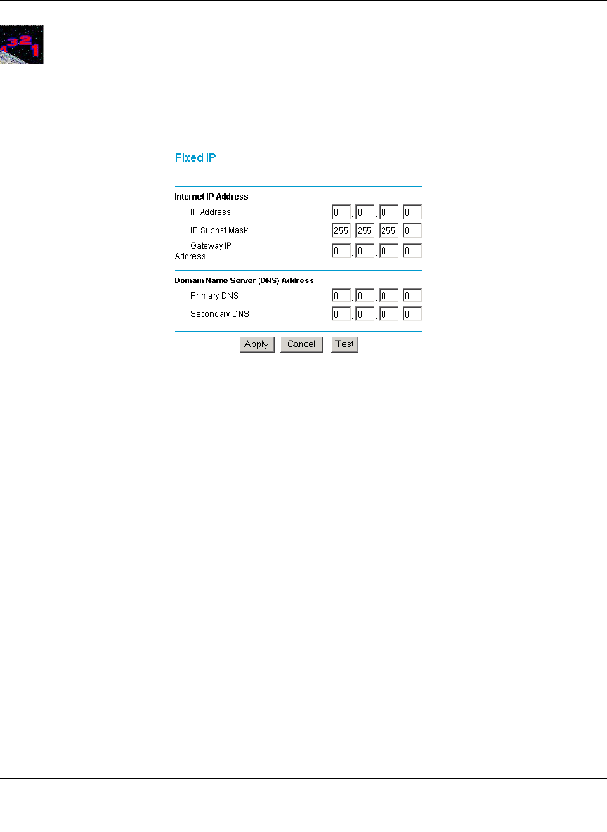
Procedure 2-6: Wizard-Detected Fixed IP (Static) Account Setup
If the Setup Wizard determines that your Internet service account uses Fixed IP assignment, you
will be directed to the menu shown in Figure 2-10 below:
Figure 2-10: Setup Wizard menu for Fixed IP address
1. Enter your assigned IP Address, Subnet Mask, and the IP Address of your ISP’s gateway
router. This information should have been provided to you by your ISP. You will need the
configuration parameters from your ISP you recorded in “Record Your Internet Connection
Information” on page 2-3.
2. Enter the IP address of your ISP’s Primary DNS Server. If a Secondary DNS Server address is
available, enter it also.
A DNS servers are required to perform the function of translating an Internet name such as
www.netgear.com to a numeric IP address. For a fixed IP address configuration, you must
obtain DNS server addresses from your ISP and enter them manually here. You should
reboot your PCs after configuring the firewall for these settings to take effect.
3. Click on Apply to save the settings.
4. Click on the Test button to test your Internet connection. If the NETGEAR website does not
appear within one minute, refer to Chapter 8, Troubleshooting.
FVM318.book Page 13 Wednesday, September 18, 2002 5:20 PM
Reference Manual for the Model FVM318 Cable/DSL ProSafe Wireless VPN Security Firewall
2-14 Connecting the Firewall to the Internet
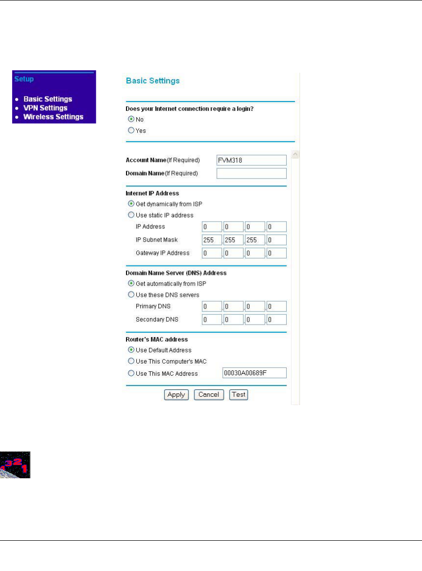
Manually Configuring Your Internet Connection
You can manually configure your firewall using the menu below, or you can allow the Setup
Wizard to determine your configuration as described in the previous section.
Figure 2-11: Browser-based configuration Basic Settings menu
Procedure 2-7: Manual Configuration
You can manually configure the firewall in the Basic Settings menu shown in Figure 2-13 using
these steps:
FVM318.book Page 14 Wednesday, September 18, 2002 5:20 PM

Reference Manual for the Model FVM318 Cable/DSL ProSafe Wireless VPN Security Firewall
Connecting the Firewall to the Internet 2-15
1. Select whether your Internet connection requires a login.
Select Broadband with Login if you normally must launch a login program such as Enternet or
WinPOET in order to access the Internet.
Note: If you are a Telstra BigPond cable modem customer, or if you are in an area such as
Austria that uses PPTP, login is required. If so, select BigPond or PPTP from the Internet
Service Type drop down box.
2. Enter your Account Name (may also be called Host Name) and Domain Name.
These parameters may be necessary to access your ISP’s services such as mail or news servers.
3. (If displayed) Enter the PPPoE login user name and password provided by your ISP.
These fields are case sensitive. If you wish to change the login timeout, enter a new value in
minutes.
Note: You will no longer need to launch the ISP’s login program on your PC in order to access
the Internet. When you start an Internet application, your firewall will automatically log you
in.
4. Internet IP Address:
If your ISP has assigned you a permanent, fixed (static) IP address for your PC, select “Use
static IP address”. Enter the IP address that your ISP assigned. Also enter the netmask and the
Gateway IP address. The Gateway is the ISP’s router to which your firewall will connect.
5. Domain Name Server (DNS) Address:
If you know that your ISP does not automatically transmit DNS addresses to the firewall
during login, select “Use these DNS servers” and enter the IP address of your ISP’s Primary
DNS Server. If a Secondary DNS Server address is available, enter it also.
A DNS server is a host on the Internet that translates Internet names (such as
www.netgear.com) to numeric IP addresses. Typically your ISP transfers the IP address of
one or two DNS servers to your firewall during login. If the ISP does not transfer an
address, you must obtain it from the ISP and enter it manually here. If you enter an address
here, you should reboot your PCs after configuring the firewall.
6. Router’s MAC Address:
This section determines the Ethernet MAC address that will be used by the firewall on the
Internet port. Some ISPs will register the Ethernet MAC address of the network interface card
in your PC when your account is first opened. They will then only accept traffic from the
MAC address of that PC. This feature allows your firewall to masquerade as that PC by
“cloning” its MAC address.
To change the MAC address, select “Use this Computer’s MAC address.” The firewall will
then capture and use the MAC address of the PC that you are now using. You must be using
the one PC that is allowed by the ISP. Or, select “Use this MAC address” and enter it.
FVM318.book Page 15 Wednesday, September 18, 2002 5:20 PM

Reference Manual for the Model FVM318 Cable/DSL ProSafe Wireless VPN Security Firewall
2-16 Connecting the Firewall to the Internet
7. Click Apply to save your settings.
8. Click on the Test button to test your Internet connection.
If the NETGEAR website does not appear within one minute, refer to Chapter 8,
Troubleshooting.
FVM318.book Page 16 Wednesday, September 18, 2002 5:20 PM
Reference Manual for the Model FVM318 Cable/DSL ProSafe Wireless VPN Security Firewall
Connecting the Firewall to the Internet 2-17
Configuring Wireless Connectivity
Use the procedure below to configure an Internet connection via the serial port of your firewall.
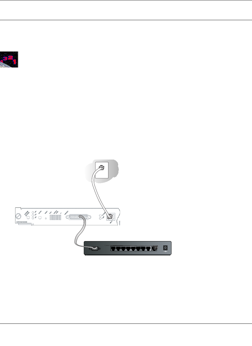
Procedure 2-8: Serial Port Internet Connection Configuration
There are three steps to configuring the serial port of your firewall for an Internet connection:
1. Connect the firewall to your ISDN or dial-up analog modem
2. Configure the firewall
3. Connect to the Internet
Follow the steps below to configure a serial port Internet connection on your firewall.
1. Connect the Firewall to your ISDN or dial-up modem
a. Turn off your Modem and connect the cable (C) from your FR328S’s serial port to the
modem.
Figure 2-12: Connect the ISDN or analog modem to the firewall
b. Turn on the modem and wait about 30 seconds for the lights to stop blinking.
MODEM 12VDC O.5A
87654321
LO CA L
10/100M
IN TERNET
ISDN or
analog modem
C
FVM318.book Page 17 Wednesday, September 18, 2002 5:20 PM
Reference Manual for the Model FVM318 Cable/DSL ProSafe Wireless VPN Security Firewall
2-18 Connecting the Firewall to the Internet
2. Configure the Serial Port of the Firewall.
Note: To connect to the firewall, your computer needs to be configured to obtain an IP address
automatically via DHCP. If you need instructions on how to do this, please refer to
Appendix C, "Preparing Your Network".
a. Use a browser to log in to the firewall at http://192.168.0.1 with its default User Name of
admin and default Password of password, or using whatever User Name, Password you
have set up.
Note: The user name and password are not the same as any user name or password you
may use to log in to your Internet connection.
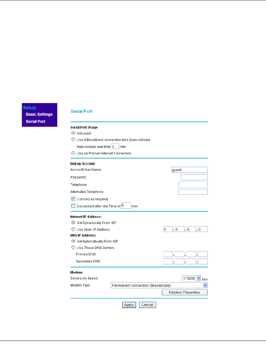
b. From the Setup menu, click the Serial Port link to display the menu below.
Figure 2-13: Setup Serial Port configuration menu
FVM318.book Page 18 Wednesday, September 18, 2002 5:20 PM
Reference Manual for the Model FVM318 Cable/DSL ProSafe Wireless VPN Security Firewall
Connecting the Firewall to the Internet 2-19
c. Choose the type of Serial Port Usage:
• Auto-rollover with a wait time in minutes
• Primary Internet connection
d. Fill in the ISP Internet configuration parameters as appropriate:
• For a Dial-up Account, enter the Account/User Name, Password, the Telephone
number to dial, an Alternative Telephone number if available. Check “Connect as
required” to enable the firewall to automatically dial the number. If you want to enable
a Idle Time disconnect, check the box and enter a time in minutes.
• To configure the TCP/IP settings, fill in whatever address parameters your ISP
provided.
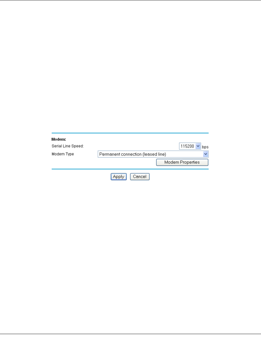
e. Configure the Modem parameters:
Figure 2-14: Modem configuration menu
• Select the Serial Line Speed.
This is the maximum speed the modem will attempt to use. For ISDN permanent
connections, the speeds are typically 64000 or 128000 bps. For dial-up modems, 56000
bps would be a typical setting.
—For ISDN, select “Permanent connection (leased line).”
—For dial-up, select your modem from the list.
—If your modem is not on the list, select “User Defined” and enter the Modem Properties.
FVM318.book Page 19 Wednesday, September 18, 2002 5:20 PM
Reference Manual for the Model FVM318 Cable/DSL ProSafe Wireless VPN Security Firewall
2-20 Connecting the Firewall to the Internet
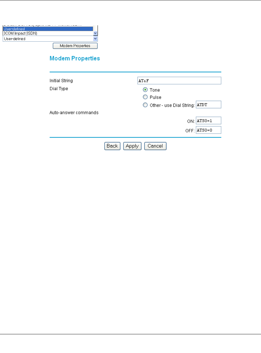
• Select the Modem Type
Figure 2-15: Modem Properties menu
• If you are using the “Generic Modem” selection and configuring your own modem
stings, fill in the Modem Properties settings.
Note: You can validate modem string settings by first connecting the modem directly
to a PC, establishing a connection to your ISP, and then copying the modem string
settings from the PC configuration and pasting them into the FR328S Modem
Properties Initial String field. For more information on this procedure, please refer to
the support area of the NETGEAR web site.
f. Click Apply to save your settings.
3. Connect to the Internet to test your configuration.
a. If you have a broadband connection, disconnect it.
b. From a workstation, open a browser and test your serial port Internet connection.
Note: The response time of your serial port Internet connection will be slower than a
broadband Internet connection.
FVM318.book Page 20 Wednesday, September 18, 2002 5:20 PM

Reference Manual for the Model FVM318 Cable/DSL ProSafe Wireless VPN Security Firewall
Connecting the Firewall to the Internet 2-21
Testing Your Internet Connection
After completing the Internet connection configuration, your can test your Internet connection.
Log in to the firewall, then, from the Setup Basic Settings link, click on the Test button. If the
NETGEAR website does not appear within one minute, refer to Chapter 8, Troubleshooting.
Your firewall is now configured to provide Internet access for your network. Your firewall
automatically connects to the Internet when one of your computers requires access. It is not
necessary to run a dialer or login application such as Dial-Up Networking or Enternet to connect,
log in, or disconnect. These functions are performed by the firewall as needed.
To access the Internet from any computer connected to your firewall, launch a browser such as
Microsoft Internet Explorer or Netscape Navigator. You should see the firewall’s Internet LED
blink, indicating communication to the ISP. The browser should begin to display a Web page.
The following chapters describe how to configure the Advanced features of your firewall, and how
to troubleshoot problems that may occur.
FVM318.book Page 21 Wednesday, September 18, 2002 5:20 PM

Reference Manual for the Model FVM318 Cable/DSL ProSafe Wireless VPN Security Firewall
2-22 Connecting the Firewall to the Internet
FVM318.book Page 22 Wednesday, September 18, 2002 5:20 PM

Protecting Your Network 3-1
Chapter 3
Protecting Your Network
This chapter describes how to use the basic firewall features of the FVM318 Cable/DSL ProSafe
Wireless VPN Security Firewall to protect your network.
Protecting Access to Your FVM318 firewall
For security reasons, the firewall has its own user name and password. Also, after a period of
inactivity for a set length of time, the administrator login will automatically disconnect. When
prompted, enter admin for the firewall User Name and password for the firewall Password.
You can use procedures below to change the firewall's password and the amount of time for the
administrator’s login timeout.
Note: The user name and password are not the same as any user name or password your may use
to log in to your Internet connection.
NETGEAR recommends that you change this password to a more secure password. The ideal
password should contain no dictionary words from any language, and should be a mixture of both
upper and lower case letters, numbers, and symbols. Your password can be up to 30 characters.
FVM318.book Page 1 Wednesday, September 18, 2002 5:20 PM
Reference Manual for the Model FVM318 Cable/DSL ProSafe Wireless VPN Security Firewall
3-2 Protecting Your Network
Procedure 3-1: Changing the Built-In Password
1. Log in to the firewall at its default LAN address of http://192.168.0.1 with its default User
Name of admin, default password of password, or using whatever User Name, Password and
LAN address you have chosen for the firewall.
Figure 3-1: Log in to the firewall
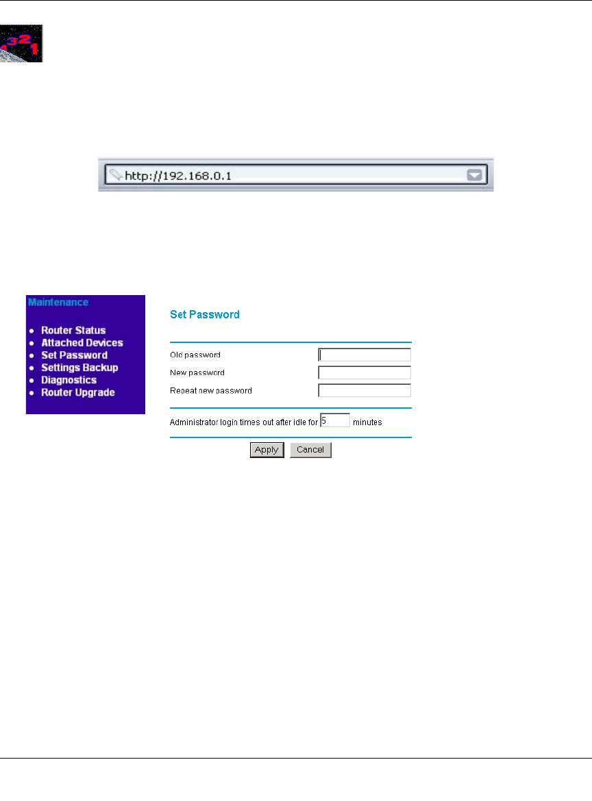
2. From the Main Menu of the browser interface, under the Maintenance heading, select Set
Password to bring up the menu shown in Figure 3-2.
Figure 3-2: Set Password menu
3. To change the password, first enter the old password, and then enter the new password twice.
4. Click Apply to save your changes.
Note: After changing the password, you will be required to log in again to continue the
configuration. If you have backed up the firewall settings previously, you should do a new
backup so that the saved settings file includes the new password.
FVM318.book Page 2 Wednesday, September 18, 2002 5:20 PM

Reference Manual for the Model FVM318 Cable/DSL ProSafe Wireless VPN Security Firewall
Protecting Your Network 3-3
Procedure 3-1: Changing the Administrator Login Timeout
For security, the administrator's login to the firewall configuration will timeout after a period of
inactivity. To change the login timeout period:
1. In the Set Password menu, type a number in ‘Administrator login times out’ field.The
suggested default value is 5 minutes.
2. Click Apply to save your changes or click Cancel to keep the current period.
Configuring Basic Firewall Services
Basic firewall services you can configure include access blocking and scheduling of firewall
security. These topics are presented below.
Blocking Functions, Keywords, Sites, and Services
The firewall provides a variety of options for blocking Internet based content and
communications services. Those basic options include:
With its content filtering feature, the FVM318 firewall prevents objectionable content from
reaching your PCs. The FR114P allows you to control access to Internet content by screening for
keywords within Web addresses. Key content filtering options include:
• Keyword blocking of newsgroup names.
• ActiveX, Java, cookie, and web proxy filtering.
• ActiveX and Java programs can be embedded is websites, and will be executed by your
computer. These programs may sometimes include malicious content.
• Cookies are small files that a website can store on your computer to track your activity.
Some cookies can be helpful, but some may compromise your privacy.
• Web proxies are computers on the Internet that act as relays for browsing. A web proxy
can be used to bypass your web blocking methods.
• Outbound Services Blocking limits access from your LAN to Internet locations or services
that you specify as off-limits.
• Denial of Service (DoS) protection. Automatically detects and thwarts Denial of Service
(DoS) attacks such as Ping of Death, SYN Flood, LAND Attack and IP Spoofing.
FVM318.book Page 3 Wednesday, September 18, 2002 5:20 PM
Reference Manual for the Model FVM318 Cable/DSL ProSafe Wireless VPN Security Firewall
3-4 Protecting Your Network
• Blocks unwanted traffic from the Internet to your LAN.
• Blocks access from your LAN to Internet locations that you specify as off-limits.
The section below explains how to configure your firewall to perform these functions.
Procedure 3-2: Block Functions, Keywords, and Sites
The FVM318 firewall allows you to restrict access to Internet content based on functions such as
Java or Cookies, Web addresses and Web address keywords.
1. Log in to the firewall at its default LAN address of http://192.168.0.1 with its default User
Name of admin, default password of password, or using whatever User Name, Password and
LAN address you have chosen for the firewall.
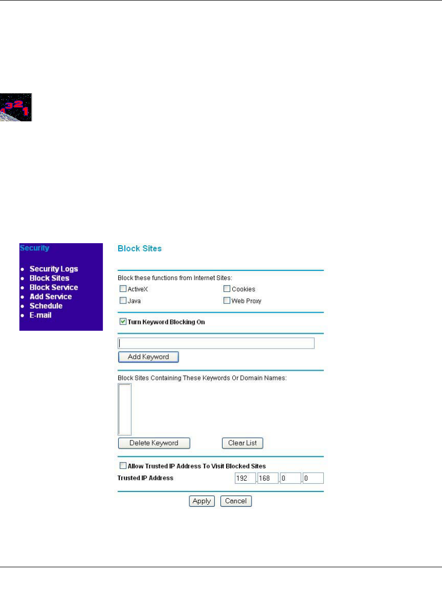
2. Click on the Block Sites link of the Security menu.
Figure 3-3: Block Sites menu
FVM318.book Page 4 Wednesday, September 18, 2002 5:20 PM

Reference Manual for the Model FVM318 Cable/DSL ProSafe Wireless VPN Security Firewall
Protecting Your Network 3-5
3. To block ActiveX, Java, Cookies, or Web Proxy functions for all Internet sites, click the check
box next to the function and then click Apply.
4. To enable keyword blocking, check “Turn keyword blocking on”, enter a keyword or domain
in the Keyword box, click Add Keyword, then click Apply.
Some examples of Keyword application follow:
• If the keyword “XXX” is specified, the URL <http://www.badstuff.com/xxx.html> is
blocked, as is the newsgroup alt.pictures.xxx.
• If the keyword “.com” is specified, only websites with other domain suffixes (such as .edu
or .gov) can be viewed.
• Enter the keyword “.” to block all Internet browsing access.
Up to 32 entries are supported in the Keyword list.
5. To delete a keyword or domain, select it from the list, click Delete Keyword, then click Apply.
6. To specify a Trusted User, enter that PC’s IP address in the Trusted User box and click Apply.
You may specify one Trusted User, which is a PC that will be exempt from blocking and
logging. Since the Trusted User will be identified by an IP address, you should configure that
PC with a fixed IP address.
Block Services
Firewalls are used to regulate specific traffic passing through from one side of the firewall to the
other. You can restrict outbound (LAN to WAN) traffic to what outside resources you want local
users to be able to access. In addition to the kind of blocking of sites discussed above, you can
block services like Telnet or Instant Messenger.
By default, the FR114P regulates inbound and outbound traffic in these ways:
• Inbound: Block all access from outside except responses to requests from the LAN side.
• Outbound: Allow all access from the LAN side to the outside.
You may define exceptions to the default outbound settings by adding Block Services definitions
to the Outbound Services table. In this way, you can block or allow access based on the service or
application destination IP addresses, and time of day. You can also choose to log traffic that
matches or does not match what you have defined.
FVM318.book Page 5 Wednesday, September 18, 2002 5:20 PM
Reference Manual for the Model FVM318 Cable/DSL ProSafe Wireless VPN Security Firewall
3-6 Protecting Your Network
Procedure 3-3: Block Services
1. Log in to the firewall at its default LAN address of http://192.168.0.1 with its default User
Name of admin, default password of password, or using whatever User Name, Password and
LAN address you have chosen for the firewall.
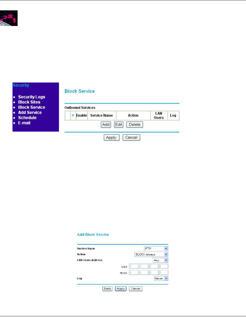
2. Click on the Block Sites link of the Security menu to display the Block Services menu shown
in Figure 3-4:
Figure 3-4: Block Services menu
• To create a new Block Services rule, click the Add button.
• To edit an existing Block Services rule, select its button on the left side of the table and
click Edit.
• To delete an existing Block Services rule, select its button on the left side of the table and
click Delete.
3. Modify the menu shown below for defining or editing a how a service is regulated.
Figure 3-5: Add Block Services menu
FVM318.book Page 6 Wednesday, September 18, 2002 5:20 PM

Reference Manual for the Model FVM318 Cable/DSL ProSafe Wireless VPN Security Firewall
Protecting Your Network 3-7
The parameters are:
•Service
From this list, select the application or service to be allowed or blocked. The list already
displays many common services, but you are not limited to these choices. Use the Add
Services menu to add any additional services or applications that do not already appear.
• Action
Choose how you would like this type of traffic to be handled. You can block or allow
always, or you can choose to block or allow according to the schedule you have defined in
the Schedule menu.
• LAN Users Address
Specify traffic originating on the LAN (outbound), and choose whether you would like the
traffic to be restricted by source IP address. You can select Any, a Single address, or a
Range. If you select a range of addresses, enter the range in the start and finish boxes. If
you select a single address, enter it in the start box.
•Log
You can select whether the traffic will be logged. The choices are:
• Never - no log entries will be made for this service.
• Always - any traffic for this service type will be logged.
• Match - traffic of this type which matches the parameters and action will be logged.
• Not match - traffic of this type which does not match the parameters and action will be
logged.
4. Click Apply to save your definition.
Setting Times and Scheduling Firewall Services
The FVM318 firewall uses the Network Time Protocol (NTP) to obtain the current time and date
from one of several Network Time Servers on the Internet. In order to localize the time for your
log entries, you must select your Time Zone from the list.
Procedure 3-4: Setting Your Time Zone
In order to localize the time for your log entries, you must specify your Time Zone:
FVM318.book Page 7 Wednesday, September 18, 2002 5:20 PM
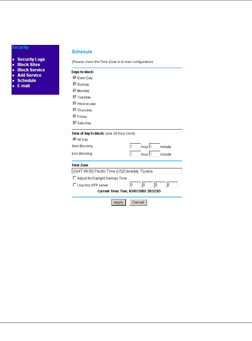
Reference Manual for the Model FVM318 Cable/DSL ProSafe Wireless VPN Security Firewall
3-8 Protecting Your Network
1. Log in to the firewall at its default LAN address of http://192.168.0.1 with its default User
Name of admin, default password of password, or using whatever User Name, Password and
LAN address you have chosen for the firewall.
2. Click on the Schedule link of the Security menu to display menu shown below.
Figure 3-6: Schedule Services menu
3. Select your Time Zone. This setting will be used for the blocking schedule according to your
local time zone and for time-stamping log entries.
Check the Daylight Savings Time box if your time zone is currently in daylight savings time.
Note: If your region uses Daylight Savings Time, you must manually check Adjust for
Daylight Savings Time on the first day of Daylight Savings Time, and uncheck it at the end.
Enabling Daylight Savings Time will cause one hour to be added to the standard time.
4. The firewall has a list of publicly available NTP servers. If you would prefer to use a particular
NTP server as the primary server, enter its IP address under Use this NTP Server.
5. Click Apply to save your settings.
FVM318.book Page 8 Wednesday, September 18, 2002 5:20 PM

Reference Manual for the Model FVM318 Cable/DSL ProSafe Wireless VPN Security Firewall
Protecting Your Network 3-9
Procedure 3-5: Scheduling Firewall Services
If you enabled services blocking in the Block Services menu or Port forwarding in the Ports menu,
you can set up a schedule for when blocking occurs or when access isn't restricted.
1. Log in to the firewall at its default LAN address of http://192.168.0.1 with its default User
Name of admin, default password of password, or using whatever User Name, Password and
LAN address you have chosen for the firewall.
2. Click on the Schedule link of the Security menu to display menu shown in the “Schedule
Services menu“ on page -8.
3. To block Internet services based on a schedule, select Every Day or select one or more days. If
you want to limit access completely for the selected days, select All Day. Otherwise, to limit
access during certain times for the selected days, enter Start Blocking and End Blocking times.
Note: Enter the values as 24-hour time. For example, 10:30 am would be 10 hours and 30
minutes and 10:30 pm would be 22 hours and 30 minutes.
4. Click Apply
FVM318.book Page 9 Wednesday, September 18, 2002 5:20 PM

Reference Manual for the Model FVM318 Cable/DSL ProSafe Wireless VPN Security Firewall
3-10 Protecting Your Network
FVM318.book Page 10 Wednesday, September 18, 2002 5:20 PM
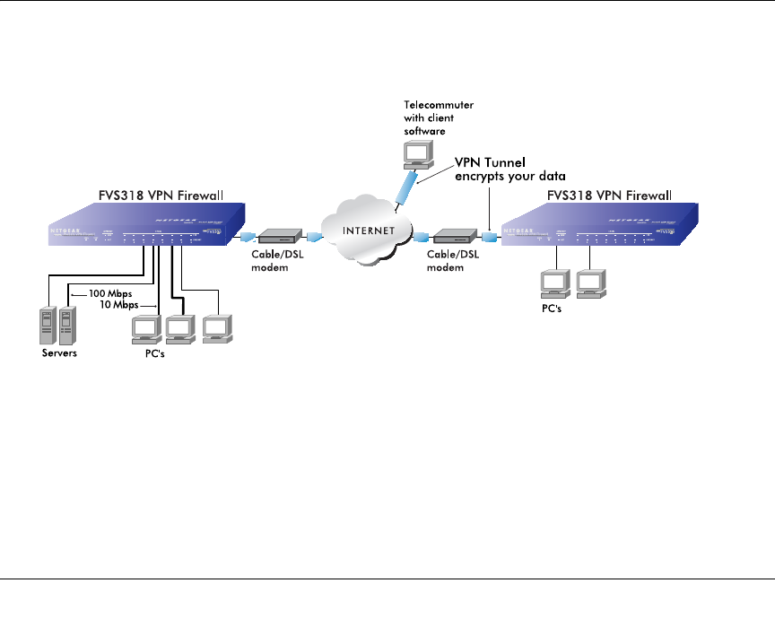
Virtual Private Networking 4-1
Chapter 4
Virtual Private Networking
This chapter describes how to use the virtual private networking (VPN) features of the FVM318
firewall. VPN communications paths are called tunnels. VPN tunnels provide secure, encrypted
communications between your local network and a remote network or computer.
Network to Network and Remote Computer to Network VPNs
Two common scenarios for configuring VPN tunnels are between two or more networks, and
between a remote computer and a network. The FVS318 supports these configurations:
Figure 4-1: Secure access through FVS318 VPN routers
• Secure access between networks, such as a branch or home office and a main office.
A VPN between two or more NETGEAR VPN-enabled routers is a good way to connect
branch or home offices and business partners over the Internet. VPN tunnels also enable
FVM318.book Page 1 Wednesday, September 18, 2002 5:20 PM
Reference Manual for the Model FVM318 Cable/DSL ProSafe Wireless VPN Security Firewall
4-2 Virtual Private Networking
access to network resources when NAT is enabled and remote computers have been assigned
private IP addresses.
• Secure access from a remote PC, such as a telecommuter connecting to an office network.
VPN client access allows a remote PC to connect to your network from any location on the
Internet. In this case, the remote PC is one tunnel endpoint, running VPN client software. The
FVM318 firewall router on your network is the other tunnel endpoint
• The FVM318 firewall supports up to eight concurrent tunnels.
These scenarios are described below.
Planning a VPN
When you set up a VPN, it is helpful to plan the network configuration and record the
configuration parameters on a worksheet. These topics are discussed below.
VPN Configuration Choices
When planning your VPN, you must make a few choices first:
• To set up a VPN connection, you must configure each endpoint with specific identification and
connection information describing the other endpoint. This set of configuration information
defines a security association (SA) between the two points. The FVS318 is capable of eight
Security Associations which are commonly referred to as tunnels.
• Will the remote end be a network or a single PC?
Note: To connect remote networks, the LAN IP address ranges of each connected network
must be different. The connection will not work if both ends are using the NETGEAR default
address range of 192.168.0.x.
Note: The FVM318 firewall uses industry standard VPN protocols. However, due to
variations in how manufacturers interpret these standards, many VPN products are not
interoperable. NETGEAR provides support for connections between FVM318 firewalls,
and between an FVM318 firewall and the SafeNet SoftRemote VPN Client for
Windows. Although the FVS318 can interoperate with many other VPN products, it is
not possible for NETGEAR to provide specific technical support for every other
interconnection. Please see NETGEAR's web site for additional VPN information.
FVM318.book Page 2 Wednesday, September 18, 2002 5:20 PM
Reference Manual for the Model FVM318 Cable/DSL ProSafe Wireless VPN Security Firewall
Virtual Private Networking 4-3
• At least one side must have a fixed IP address.
If one side has a dynamic IP address, the side with a dynamic IP address must always be the
initiator of the connection.
• Will you use the typical automated Internet Key Exchange (IKE) setup, or a Manual Keying
setup in which you must specify each phase of the connection?
IKE is an automated method for establishing a shared security policy and authenticated keys.
• What level of encryption will you use, 56 bit DES or 168 bit 3DES? 3DES is more secure but
the throughput will be slower.
Sample Network to Network VPN Tunnel Configuration Worksheet
The sample configuration worksheet below is filled in with the parameters used in the procedure
examples below. A blank worksheet is provided below at “Network to Network IKE VPN Tunnel
Configuration Worksheet” on page 4-26.
Table 4-1. Sample Network to Network IKE VPN Tunnel Configuration Worksheet
IKE Tunnel Security Association Settings
Connection Name: VPNAB
PreShared Key:r>T(h4&3@#kB
Secure Association -- Main Mode or Aggressive Mode: Main
Perfect Forward Secrecy: Enabled
Encryption Protocol -- Null, 56 bit DES, or 168 bit 3DES: DES
Key Life in seconds: 3600 (1 hour)
IKE Life Time in seconds: 28800 (8 hours)
FVM318 firewall Network IP Settings
Network Local IPSec
Identifier LAN IP
Network Address Subnet Mask Gateway IP
(WAN IP Address)
LAN A LAN_A 192.168.3.1 255.255.255.0 24.0.0.1
LAN B LAN_B 192.168.0.1 255.255.255.0 10.0.0.1
FVM318.book Page 3 Wednesday, September 18, 2002 5:20 PM
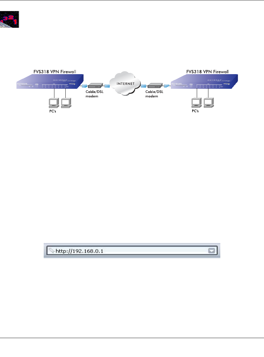
Reference Manual for the Model FVM318 Cable/DSL ProSafe Wireless VPN Security Firewall
4-4 Virtual Private Networking
Procedure 4-1: Configuring a Network to Network VPN Tunnel
Follow this procedure to configure a VPN tunnel between two LANs via a FVS318 at each end.
Figure 4-2: LAN to LAN VPN access through an FVS318 to an FVS318
1. Set up the two LANs to have different IP address ranges.
The procedures below refer to the “Sample Network to Network IKE VPN Tunnel
Configuration Worksheet” on page 4-3.
To configure your actual network, print and fill out the blank “Network to Network IKE VPN
Tunnel Configuration Worksheet” on page 4-26 for your network configuration. Then follow
the procedures below.
a. Log in to the first FVS318 firewall (A) at its default LAN address of http://192.168.0.1
with its default User Name of admin and default Password of password, or using
whatever User Name, Password you have set up.
Figure 4-3: Log in
AB
FVM318.book Page 4 Wednesday, September 18, 2002 5:20 PM
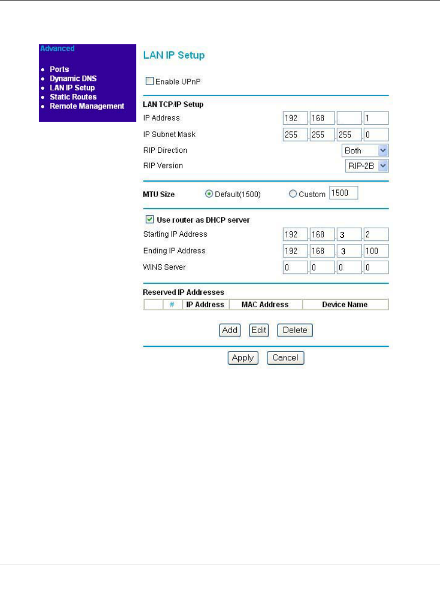
Reference Manual for the Model FVM318 Cable/DSL ProSafe Wireless VPN Security Firewall
Virtual Private Networking 4-5
b. Click the LAN IP Setup link from the Advanced section of the main menu to display the
menu shown in Figure 4-4.
Figure 4-4: Configuring the Local LAN (A) via the LAN IP Setup Menu
c. Change the settings as follows:
• IP Address to 192.168.3.1
• DHCP Starting Address to 192.168.3.2
• DHCP Ending Address to 192.168.3.100
• Change any Reserved IP Addresses to be part of the 192.168.3.x network
Note: If Port Forwarding, Trusted User, or Static Routes are set up, you will need to
change these configurations to match the 192.168.3.x network as well.
FVM318.book Page 5 Wednesday, September 18, 2002 5:20 PM
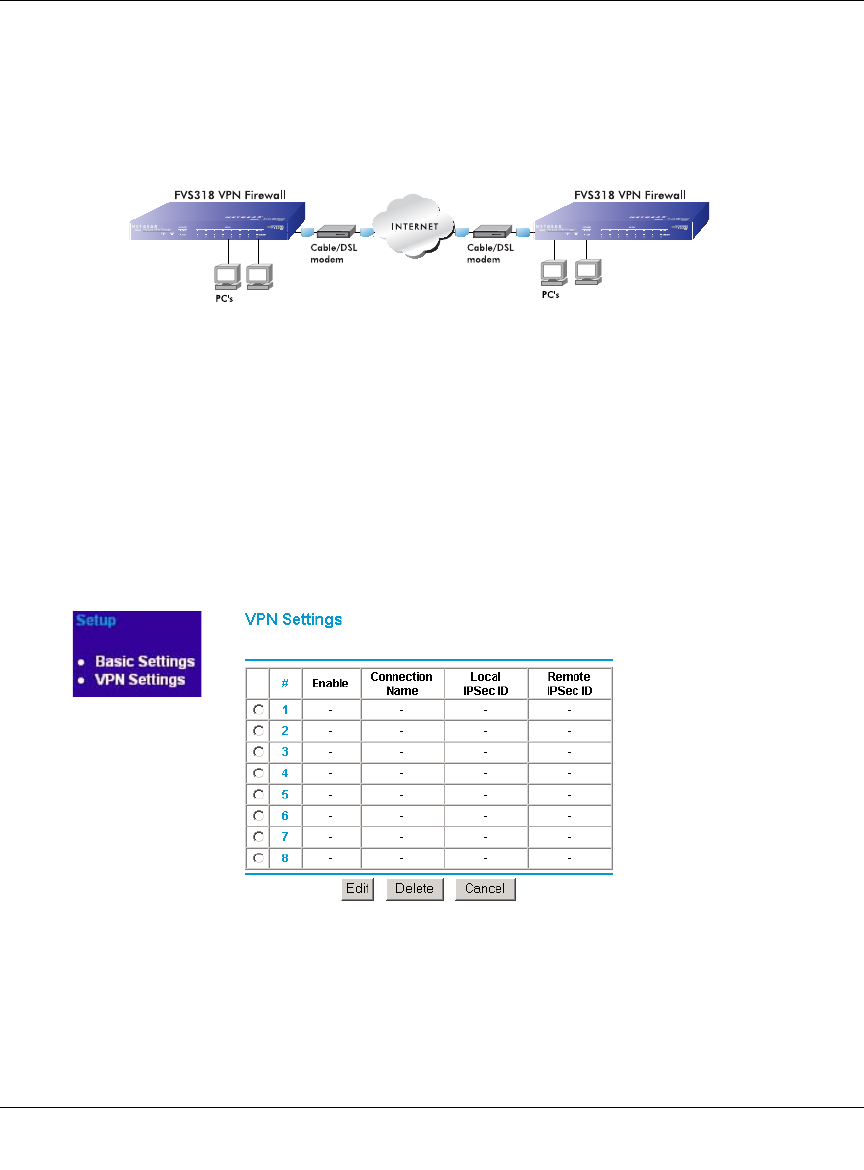
Reference Manual for the Model FVM318 Cable/DSL ProSafe Wireless VPN Security Firewall
4-6 Virtual Private Networking
d. Click Apply.
Because you changed the firewall’s IP address, you are now disconnected.
e. Reboot all PCs on network A. The network configuration should now look like this:
Figure 4-5: Local LAN (A) configuration
2. Configure the VPN Settings of the FVS318 firewall (A) on the local LAN.
a. Log in to the first FVS318 router (A) at its new LAN address of http://192.168.3.1 with its
default User Name of admin and default Password of password, or using whatever User
Name and Password you set up.
b. From the Setup menu, click the VPN Settings link. The VPN Settings window opens as
shown in Figure 4-6 below:
Figure 4-6: VPN Settings menu
AB
192.168.3.1 192.168.0.1
FVM318.book Page 6 Wednesday, September 18, 2002 5:20 PM
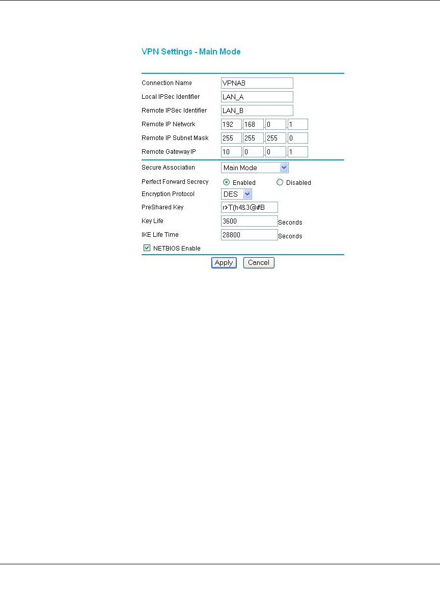
Reference Manual for the Model FVM318 Cable/DSL ProSafe Wireless VPN Security Firewall
Virtual Private Networking 4-7
c. Click the button next to an unused tunnel profile in the table and click Edit.
The VPN Settings - Main Mode window opens as shown in Figure 4-7 below:
Figure 4-7: LAN A VPN Settings - Main Mode IKE Edit menu
d. Fill in the Connection Name VPN settings.
• In the Connection Name box, type the name for the Security Association of LANs A
and B. For example, enter VPNAB as the Connection Name.
• Enter the unique Local IPSec Identifier name for the local FVS318 (A). For example,
enter LAN_A.
Note: This IPSec name must not be used in any other SA definitions in this VPN
network.
• Enter the unique Remote IPSec Identifier name for the remote FVS318 (B).For
example, enter LAN_B.
• Enter the Remote IP Address and IP Subnet Mask.
In this case, the Remote network address is the LAN network address of the second
FVS318 (B), which is 192.168.0.1 and the Subnet Mask is 255.255.255.0.
FVM318.book Page 7 Wednesday, September 18, 2002 5:20 PM

Reference Manual for the Model FVM318 Cable/DSL ProSafe Wireless VPN Security Firewall
4-8 Virtual Private Networking
• Enter the Remote Gateway IP Address which is the WAN IP Address for the second
FVS318 (B). In this example, use 10.0.0.1 for the Gateway IP Address.
You can look up the Remote Gateway IP Address by viewing the WAN Status screen
of the second FVS318 (B). When FVS318 (B) is connected to the Internet, log in, go
go to its Maintenance menu Router Status link. If you find the WAN Port DHCP field
says “DHCP Client” or “PPPOE,” then it is a dynamic address. For a dynamic address
enter 0.0.0.0 in the configuration screen of the FVS318 on LAN A as the WAN IP
Address for the FVS318 on LAN (B).
Note: Only one side may have a dynamic IP address, and that side must always
initiate the connection.
e. Under Secure Association, select Main Mode, unless you are connecting to a device that
requires Aggressive Mode, and fill in the settings below.
Note: The alternative to IKE is Manual Keying which is covered “Using Manual Keying
as an Alternative to IKE” on page 4-24.
To configure the IKE settings for firewall A, enter the following:
• Enable Perfect Forward Secrecy.
• For Encryption Protocol, select: DES.
• Enter the PreShared Key. In this example, r>T(h4&3@#kB is the PreShared Key.
With IKE, a preshared key that you make up is used for mutual identification. The
PreShared Key should be between 8 and 80 characters, and the letters are case
sensitive. Entering a combination of letters, numbers and symbols, such as
r>T(h4&3@#kB provides greater security.
• Key Life - Default is 3600 seconds (1 hour)
• IKE Life Time - Default is 28800 seconds (8 hours).
A shorter time increases security, but users will be temporarily disconnected upon
renegotiation.
f. If you need to run Microsoft networking functions such as Network Neighborhood, click
the NETBIOS Enable check box to allow NETBIOS traffic over the VPN tunnel.
g. Click Apply to save the Security Association tunnel settings into the table.
FVM318.book Page 8 Wednesday, September 18, 2002 5:20 PM
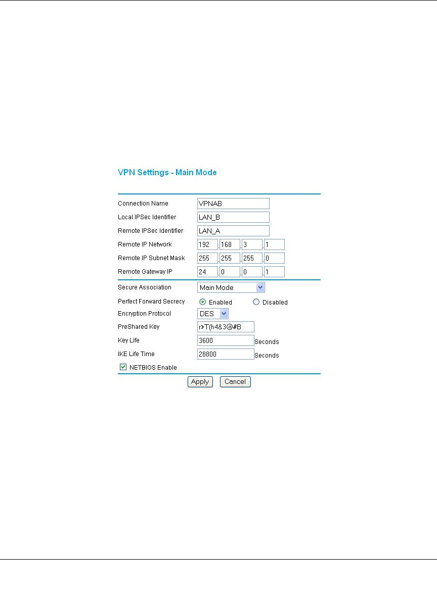
Reference Manual for the Model FVM318 Cable/DSL ProSafe Wireless VPN Security Firewall
Virtual Private Networking 4-9
3. Configure the VPN Settings of the FVS318 firewall (B) on the remote LAN.
To configure the second FVS318 (B), refer to the configuration worksheet and do the
following:
a. Log in to the FVS318 router (B) at its default LAN address of http://192.168.0.1 with its
default User Name of admin and default Password of password, or using whatever User
Name and Password you set up.
b. From the Setup menu, click the VPN Settings link. The VPN Settings window opens.
c. Click the button next to an unused profile in the table and click Edit.
The VPN Settings - Main Mode window opens as shown in Figure 4-8 below:
Figure 4-8: LAN B VPN Settings - Main Mode IKE Edit menu
d. Fill in the Connection Name VPN settings.
• In the Connection Name box, type the same Security Association name of LANs A
and B you entered for LAN A. In this case, enter VPNAB as the Connection Name.
• Enter the unique IPSec Identifiers. In this example, enter LAN_B as the Local IPSec
Identifier name for the local FVS318 (B), and LAN_B as the Remote IPSec Identifier
name for the FVS318 (A).
FVM318.book Page 9 Wednesday, September 18, 2002 5:20 PM

Reference Manual for the Model FVM318 Cable/DSL ProSafe Wireless VPN Security Firewall
4-10 Virtual Private Networking
• Enter the Remote IP Address and the Remote IP Subnet Mask.
In this example, 192.168.3.1 is the Remote network address, which is the LAN
network address of the first FVS318 (A), and 255.255.255.0 is the Subnet Mask.
• Type the Remote Gateway IP Address, which is the WAN IP address of the first
FVS318 (A). In this example, 24.0.0.1 is the Remote Gateway.
You can look up the Remote Gateway IP Address by viewing the WAN Status screen
of the second FVS318 (A). When FVS318 (A) is connected to the Internet, log in, go
to its Maintenance menu Router Status link. If you find the WAN Port DHCP field
says “DHCP Client” or “PPPOE,” then it is a dynamic address. For a dynamic address
enter 0.0.0.0 in the configuration screen of the FVS318 on LAN B as the WAN IP
Address for the FVS318 on LAN (A).
Note: Only one side may have a dynamic IP address, and that side must always
initiate the connection.
e. Under Secure Association, select Main Mode, unless you are connecting to a device that
requires Aggressive Mode, and fill in the settings below.
• Enable Perfect Forward Secrecy.
• For Encryption Protocol, select: Null.
•Enter r>T(h4&3@#kB as the PreShared Key
• Key Life - Default is 3600 seconds (1 hour)
• IKE Life Time - Default is 28800 seconds (8 hours).
f. If you need to run Microsoft networking functions such as Network Neighborhood, click
the NETBIOS Enable check box to allow NETBIOS traffic over the VPN tunnel.
g. Click Apply to save the Security Association tunnel settings into the table.
FVM318.book Page 10 Wednesday, September 18, 2002 5:20 PM
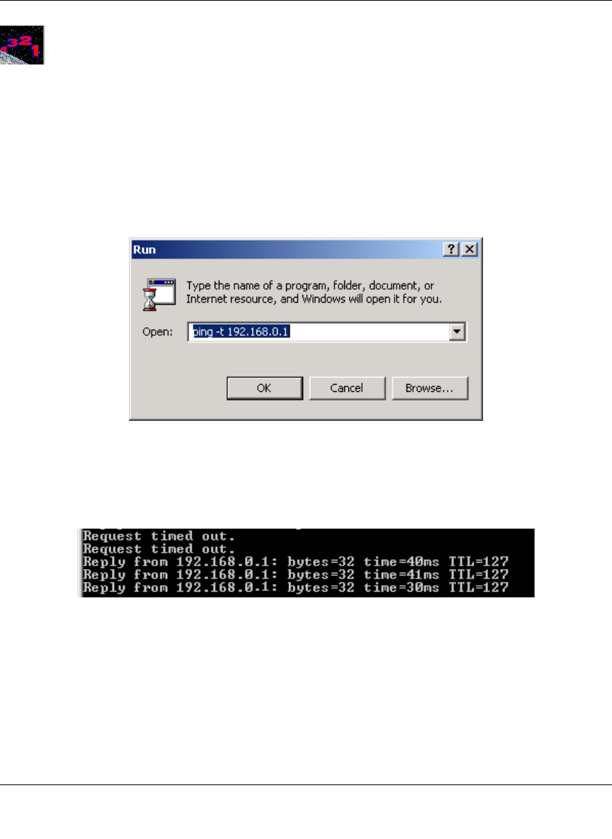
Reference Manual for the Model FVM318 Cable/DSL ProSafe Wireless VPN Security Firewall
Virtual Private Networking 4-11
Procedure 4-2: Check the VPN Connection
To check the VPN Connection, you can initiate a request from one network to the other. If one
FVS318 has a dynamically assigned WAN IP address, you must initiate the request from that
FVS318’s network. The simplest method is to ping the LAN IP address of the other FVS318.
1. Using our example, from a PC attached to the FVS318 on LAN A, on the Windows taskbar
click the Start button, and then click Run.
2. Type ping -t 192.168.0.1 , and then click OK.
Figure 4-9: Running a Ping test from Windows
3. This will cause a continuous ping to be sent to the first FVS318. After between several
seconds and two minutes, the ping response should change from “timed out” to “reply.”
Figure 4-10: Ping test results
At this point the connection is established.
Using the VPN Connection
Now that your VPN connection is working, whenever a PC on the second LAN needs to access an
IP address on the first LAN, the firewalls will automatically establish the connection.
FVM318.book Page 11 Wednesday, September 18, 2002 5:20 PM
Reference Manual for the Model FVM318 Cable/DSL ProSafe Wireless VPN Security Firewall
4-12 Virtual Private Networking
Configuring a Remote PC to Network VPN
This procedure describes linking a remote PC and a LAN. The LAN will connect to the Internet
using an FVS318 with a fixed IP address. The PC can be connected to the Internet through dialup,
cable or DSL modem, or other means, and we will assume it has a dynamically assigned IP
address.
The PC must have a VPN client program that supports IPSec. NETGEAR recommends and
supports the SafeNet SoftRemote (or Soft-PK) Secure VPN Client for Windows, Version 5 or later.
The SafeNet VPN Client can be purchased from SafeNet at http://www.safenet-inc.com.
Sample PC to Network VPN Tunnel Configuration Worksheet
The sample configuration worksheet below is filled in with the parameters used in the procedure
examples below. A blank worksheet is at, “PC to Network IKE VPN Tunnel Settings
Configuration Worksheet” on page 4-27.
Table 4-2: Sample PC to Network IKE VPN Tunnel Settings Configuration Worksheet
IKE Tunnel Security Association Settings
Connection Name: VPNLANPC
PreShared Key:r>T(h4&3@#kB
Secure Association -- Main Mode or Aggressive Mode: Main
Perfect Forward Secrecy: Enabled
Encryption Protocol -- Null, 56 bit DES, or 168 bit 3DES: DES
Key Life in seconds: 3600 (1 hour)
IKE Life Time in seconds: 28800 (8 hours)
FVM318 firewall Network and PC IP Settings
Local IPSec
Identifier LAN IP
Network Address Subnet Mask Gateway IP
(WAN IP Address)
Network: LAN A LANAPCIPSEC 192.168.3.1 255.255.255.0 24.0.0.1
Computer: PC PCIPSEC 192.168.100.2 255.255.255.255 0.0.0.0
FVM318.book Page 12 Wednesday, September 18, 2002 5:20 PM
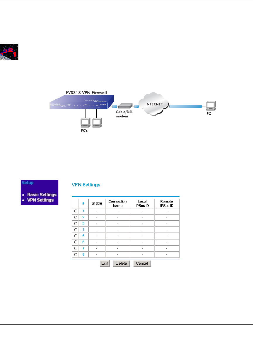
Reference Manual for the Model FVM318 Cable/DSL ProSafe Wireless VPN Security Firewall
Virtual Private Networking 4-13
Note: If your situation is different, for example, if your remote PC is connected through a simple
cable/DSL router, or if you wish to use different VPN client software, please refer to NETGEAR's
web site for additional VPN applications information.
Procedure 4-3: Configuring a Remote PC to Network VPN
1. Configure the VPN Tunnel on the FVS318 (A) firewall.
To configure the firewall, follow these steps:
a. From the Setup Menu, click the VPN Settings link to open the window in Figure 4-6:
Figure 4-11: VPN Settings Window
A
192.168.3.1
FVM318.book Page 13 Wednesday, September 18, 2002 5:20 PM
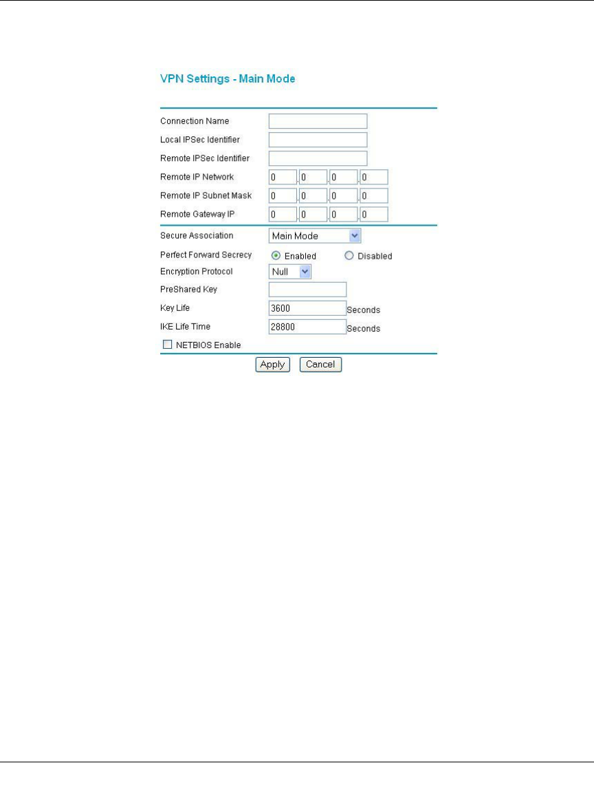
Reference Manual for the Model FVM318 Cable/DSL ProSafe Wireless VPN Security Firewall
4-14 Virtual Private Networking
b. Click the button next to an unused profile in the table and click Edit.
The VPN Settings - IKE window opens as shown in Figure 4-12 below:
Figure 4-12: VPN Edit menu for connecting with a VPN client
c. Choose Main Mode for IKE automated method for establishing a shared security policy
and authenticated keys.
d. Type VPNLANPC in the Connection Name box for this Security Association tunnel.
Note: This name must match the name of the Security Association defined in the VPN
client on the remote PC.
e. Enter LANAPCIPSEC as the Local IPSec Identifier for the FVS318 on LAN A.
Note: This IPSec name must not be used in any other SA definitions in this VPN network.
f. Enter PCIPSEC as the Remote IPSec Identifier for the PC.
g. In this case, the remote network is a single PC, and its IP address is unknown since it will
usually be assigned dynamically by the user’s ISP. We will choose an arbitrary “fixed
virtual” IP address to define this connection. This IP address will be used in the
configuration of the VPN client. For this example, enter 192.168.100.2 as the Remote IP
Network.
FVM318.book Page 14 Wednesday, September 18, 2002 5:20 PM

Reference Manual for the Model FVM318 Cable/DSL ProSafe Wireless VPN Security Firewall
Virtual Private Networking 4-15
h. Since the remote network is a single PC, enter 255.255.255.255 for the Subnet Mask.
i. Since the remote PC has a dynamically assigned IP address, enter 0.0.0.0 as the Remote
Gateway IP Address.
Note: Only one side may have a dynamic IP address, and that side must always initiate the
connection.
j. Under Secure Association, for IKE, select Main Mode, unless you are connecting to a
device that requires Aggressive Mode, and fill in the settings below.
k. Enable Perfect Forward Secrecy.
l. For Encryption Protocol, select: DES
m. Enter the case sensitive PreShared Key: r>T(h4&3@#kB
This combination of letters, numbers and symbols, provides greater security.
n. Key Life - Default is 3600 seconds (1 hour)
o. IKE Life Time - Default is 28800 seconds (8 hours).
A shorter time increases security, but users will be temporarily disconnected upon
renegotiation.
p. If you need to run Microsoft networking functions such as Network Neighborhood, click
the NETBIOS Enable check box to allow NETBIOS traffic over the VPN tunnel.
q. Click Apply to save the Security Association tunnel settings into the table.
2. Install the SafeNet VPN Client Software on the PC.
a. Install the SafeNet Secure VPN Client.
Note: You may need to insert your Windows CD to complete the installation.
—If you do not have a modem or dial-up adapter installed in your PC, you may see the
warning message stating “The SafeNet VPN Component requires at least one dial-up
adapter be installed.” You can disregard this message.
—Install the IPSec Component.
You may have the option to install either or both of the VPN Adapter or the IPSec
Component. The VPN Adapter is not necessary.
b. Reboot your PC after installing the client software.
FVM318.book Page 15 Wednesday, September 18, 2002 5:20 PM
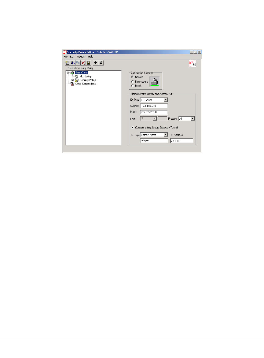
Reference Manual for the Model FVM318 Cable/DSL ProSafe Wireless VPN Security Firewall
4-16 Virtual Private Networking
3. Configure the SafeNet software via its Security Policy Editor
a. Run the SafeNet Security Policy Editor program and, using the “Sample PC to Network
IKE VPN Tunnel Settings Configuration Worksheet” on page 4-12, create a VPN
Connection.
Figure 4-13: Security Policy Editor New Connection
• From the Edit menu of the Security Policy Editor, click Add, then Connection. A
“New Connection” listing appears in the list of policies.
• Rename the “New Connection” so that it matches the Connection Name you entered
in the VPN Settings of the FVS318 (A). In this example, it would be VPNLANPC.
• In the Connection Security box, select Secure.
• In the ID Type menu, select IP Subnet.
• In the Subnet field, type 192.168.3.0 for the network address of the FVS318. In this
example, 192.168.3.0 would be used. The network address is the LAN IP Address of
the FVS318 with 0 as the last number.
• In the Mask field, type 255.255.255.0 as the LAN Subnet Mask of the FVS318
• In the Protocol menu, select All to allow all traffic through the VPN tunnel.
•Check the Connect using Secure Gateway Tunnel checkbox.
• In the ID Type menu below the checkbox, select IP Address.
FVM318.book Page 16 Wednesday, September 18, 2002 5:20 PM
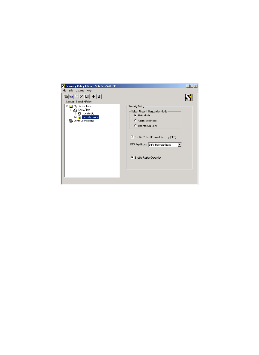
Reference Manual for the Model FVM318 Cable/DSL ProSafe Wireless VPN Security Firewall
Virtual Private Networking 4-17
• Enter the public (WAN) IP Address of the FVS318 in the field directly below the ID
Type menu. In this example, 24.0.0.1 would be used.
4. Configure the Security Policy in the SafeNet VPN Client Software.
a. In the Network Security Policy list, expand the new connection by double clicking its
name or clicking on the “+” symbol.
My Identity and Security Policy subheadings appear below the connection name.
b. Click on the Security Policy subheading to show the Security Policy menu.
Figure 4-14: Security Policy Editor Security Policy
c. In the Select Phase 1 Negotiation Mode box, select Main Mode.
d. Check the Enable Perfect Forward Secrecy (PFS) checkbox.
e. For PFS Key Group, select Diffie-Helman Group 1.
f. Check the Enable Replay Detection checkbox.
FVM318.book Page 17 Wednesday, September 18, 2002 5:20 PM
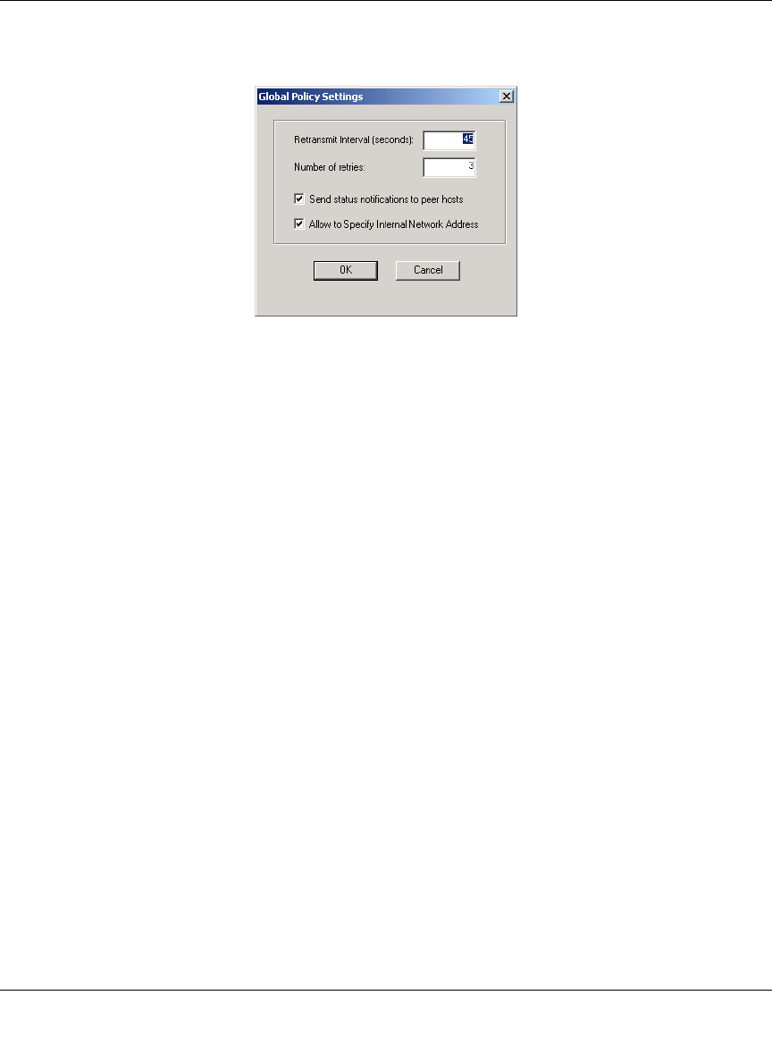
Reference Manual for the Model FVM318 Cable/DSL ProSafe Wireless VPN Security Firewall
4-18 Virtual Private Networking
g. From the Options menu at the top of the Security Policy Editor window, select Global
Policy Settings.
Figure 4-15: Security Policy Editor Global Policy Options
h. Increase the Retransmit Interval period to 45 seconds.
i. Check the Allow to Specify Internal Network Address checkbox and click OK.
5. Configure the VPN Client Identity
In this step, you will provide information about the remote VPN client PC. You will need to
provide:
• The PreShared Key that you configured in the FVS318.
• Either a fixed IP address or a “fixed virtual” IP address of the VPN client PC.
FVM318.book Page 18 Wednesday, September 18, 2002 5:20 PM
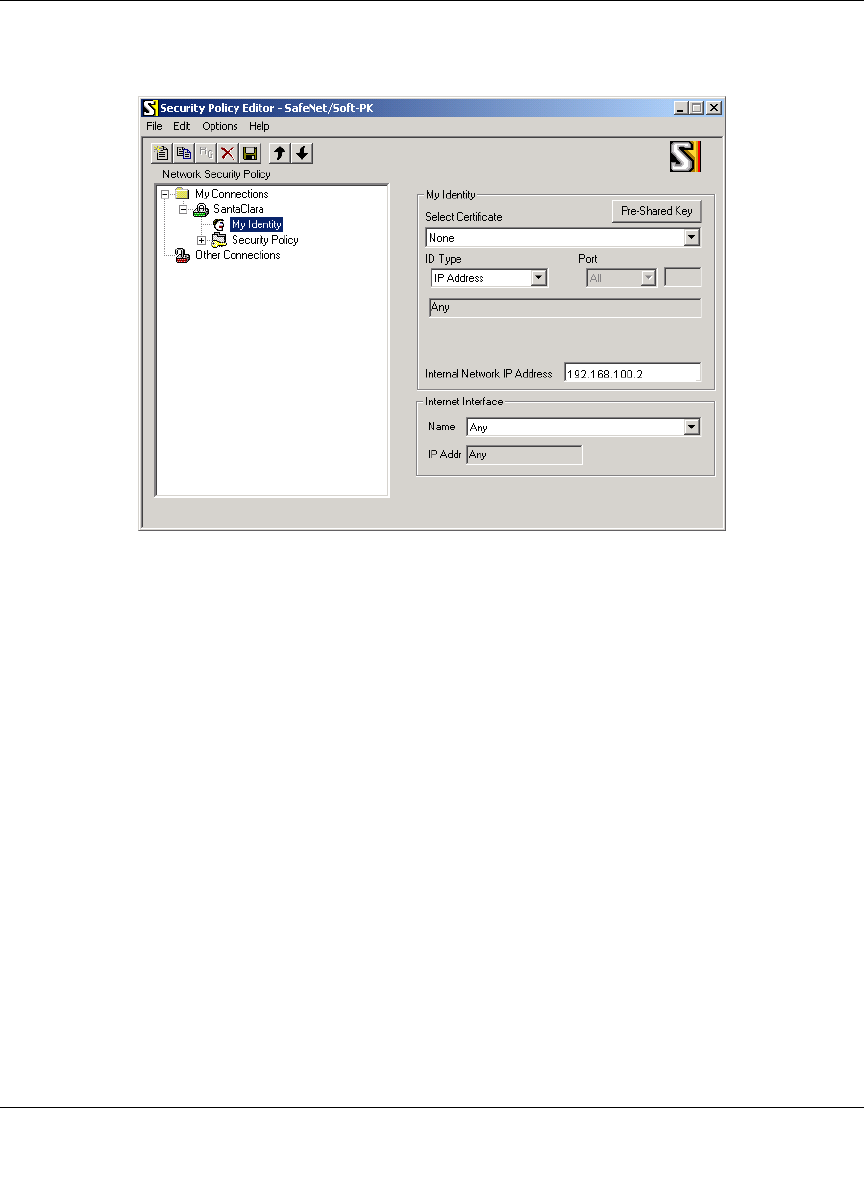
Reference Manual for the Model FVM318 Cable/DSL ProSafe Wireless VPN Security Firewall
Virtual Private Networking 4-19
a. In the Network Security Policy list on the left side of the Security Policy Editor window,
click on My Identity.
Figure 4-16: Security Policy Editor My Identity
b. In the Select Certificate menu, choose None.
c. In the ID Type menu, select IP Address.
d. If you are using a “virtual fixed” IP address as discussed in “Configuring a Remote PC to
Network VPN“ on page 4-13, enter this address in the Internal Network IP Address box.
Otherwise, leave this box empty. For this example, use 192.168.100.2.
e. In the Internet Interface box, select the adapter you use to access the Internet. Select PPP
Adapter in the Name menu if you have a dial-up Internet account. Select your Ethernet
adapter if you have dedicated Cable or DSL line. You may also choose Any if you will be
switching between adapters or if you have only one adapter.
f. Click the Pre-Shared Key button. In the Pre-Shared Key dialog box, click the Enter Key
button. Enter the FVS318's Pre-Shared Key and click OK. In this example,
r>T(h4&3@#kB would entered. Note that this field is case sensitive.
FVM318.book Page 19 Wednesday, September 18, 2002 5:20 PM

Reference Manual for the Model FVM318 Cable/DSL ProSafe Wireless VPN Security Firewall
4-20 Virtual Private Networking
6. Configure VPN Client Authentication Proposal.
These settings do not depend on your network information.
a. In the Network Security Policy list on the left side of the Security Policy Editor window,
expand the Security Policy heading by double clicking its name or clicking on the “+”
symbol.
b. Expand the Authentication subheading by double clicking its name or clicking on the “+”
symbol. Then select Proposal 1 below Authentication.
c. In the Authentication Method menu, select Pre-Shared key.
d. In the Encrypt Alg menu, select DES.
e. In the Hash Alg menu, select MD5.
f. In the SA Life menu, select Unspecified.
g. In the Key Group menu, select Diffie-Hellman Group 1.
7. Configure the VPN Client Key Exchange Proposal.
In this step, you will provide the type of encryption (DES or 3DES) to be used for this
connection. This selection must match your selection in the FVS318 configuration.
a. Expand the Key Exchange subheading by double clicking its name or clicking on the “+”
symbol. Then select Proposal 1 below Key Exchange.
b. In the SA Life menu, select Unspecified.
c. In the Compression menu, select None.
d. Check the Encapsulation Protocol (ESP) checkbox.
e. In the Encrypt Alg menu, select the type of encryption to correspond with what you
configured for the Encryption Protocol in the FVS318 in “Configuring a Remote PC to
Network VPN“ on page 4-13. In this example, use DES.
f. In the Hash Alg menu, select MD5.
g. In the Encapsulation menu, select Tunnel.
h. Leave the Authentication Protocol (AH) checkbox unchecked.
8. Save the VPN Client Settings.
a. From the File menu at the top of the Security Policy Editor window, select Save Changes.
After you have configured and saved the VPN client information, your PC will
automatically open the VPN connection when you attempt to access any IP addresses in
the range of the remote VPN router’s LAN.
FVM318.book Page 20 Wednesday, September 18, 2002 5:20 PM
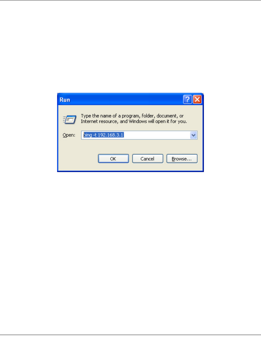
Reference Manual for the Model FVM318 Cable/DSL ProSafe Wireless VPN Security Firewall
Virtual Private Networking 4-21
Check the VPN Connection
To check the VPN Connection, you can initiate a request from the remote PC to the FVS318’s
network. Since the remote PC has a dynamically assigned WAN IP address, it must initiate the
request. The simplest method is to ping from the remote PC to the LAN IP address of the FVS318.
Using our example, start from the remote PC:
1. Establish an Internet connection from the PC.
2. On the Windows taskbar, click the Start button, and then click Run.
3. Type ping -t 192.168.3.1 , and then click OK.
Figure 4-17: Running a Ping test to LAN a from the PC
FVM318.book Page 21 Wednesday, September 18, 2002 5:20 PM
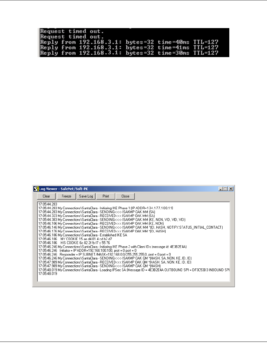
Reference Manual for the Model FVM318 Cable/DSL ProSafe Wireless VPN Security Firewall
4-22 Virtual Private Networking
This will cause a continuous ping to be sent to the first FVS318. After between several seconds
and two minutes, the ping response should change from “timed out” to “reply.”
Figure 4-18: Ping test results
Once the connection is established, you can open the browser of the remote PC and enter the LAN
IP Address of the remote FVS318. After a short wait, you should see the login screen of the
firewall.
Monitoring the PC to Network VPN Connection Using SafeNet Tools
Information on the progress and status of the VPN client connection can be viewed by opening the
SafeNet Connection Monitor or Log Viewer. To launch these functions, click on the Windows
Start button, then select Programs, then SafeNet Soft-PK, then either the Connection Monitor or
Log Viewer.
The Log Viewer screen for a successful connection is shown below:
Figure 4-19: Log Viewer screen
FVM318.book Page 22 Wednesday, September 18, 2002 5:20 PM
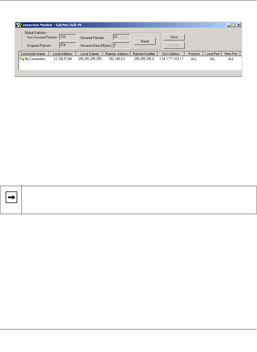
Reference Manual for the Model FVM318 Cable/DSL ProSafe Wireless VPN Security Firewall
Virtual Private Networking 4-23
The Connection Monitor screen for this connection is shown below:
Figure 4-20: Connection Monitor screen
In this example:
• The FVS318 has a public IP WAN address of 134.177.100.11
• The FVS318 has a LAN IP address of 192.168.0.1
• The VPN client PC has a dynamically assigned address of 12.236.5.184
• The VPN client PC is using a “virtual fixed” IP address of 192.168.100.100
While the connection is being established, the Connection Name field in this menu will say “SA”
before the name of the connection. When the connection is successful, the “SA” will change to the
yellow key symbol shown in the illustration above.
Deleting a Security Association
To delete a security association:
1. Log in to the firewall.
1. Click on the VPN Settings link.
2. In the VPN Settings Security Association table, select the radio button for the security
association to be deleted.
3. Click on the Delete button.
4. Click on the Update button.
Note: While your PC is connected to a remote LAN through a VPN, you might not have
normal Internet access. If this is the case, you will need to close the VPN connection in
order to have normal Internet access.
FVM318.book Page 23 Wednesday, September 18, 2002 5:20 PM
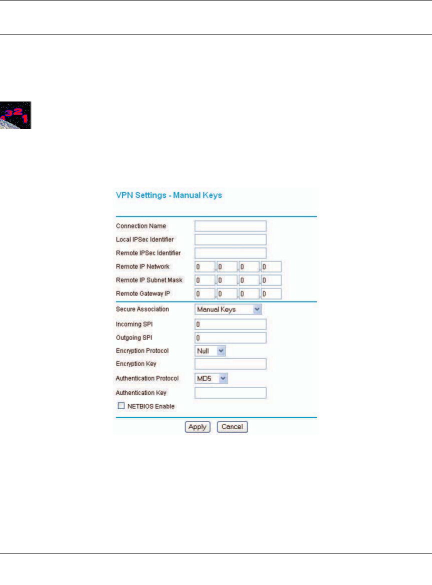
Reference Manual for the Model FVM318 Cable/DSL ProSafe Wireless VPN Security Firewall
4-24 Virtual Private Networking
Manual Keying
As an alternative to IKE, you may use Manual Keying, in which you must specify each phase of
the connection. Follow the steps to configure Manual Keying.
Procedure 4-4: Using Manual Keying as an Alternative to IKE
1. When editing the VPN Settings, you may select manual keying. At that time, the edit menu
changes to look like Figure 4-21:
Figure 4-21: VPN Edit menu for Manual Keying
2. Incoming SPI - Enter a Security Parameter Index that the remote host will send to identify the
Security Association (SA). This will be the remote host’s Outgoing SPI.
3. Outgoing SPI - Enter a Security Parameter Index that this firewall will send to identify the
Security Association (SA). This will be the remote host’s Incoming SPI.
FVM318.book Page 24 Wednesday, September 18, 2002 5:20 PM

Reference Manual for the Model FVM318 Cable/DSL ProSafe Wireless VPN Security Firewall
Virtual Private Networking 4-25
The SPI should be a string of hexadecimal [0-9,A-F] characters, and should not be used in any
other Security Association.
Tip: For simplicity or troubleshooting, the Incoming and Outgoing SPI can be identical.
4. For Encryption Protocol, select one:
a. Null - Fastest, but no security.
b. DES - Faster but less secure than 3DES.
c. 3DES - (Triple DES) Most secure.
5. Enter a hexadecimal Encryption Key
— For DES, enter 16 hexadecimal [0-9,A-F] characters.
— For 3DES, enter 48 hexadecimal [0-9,A-F] characters.
The encryption key must match exactly the key used by the remote router or host.
6. Select the Authentication Protocol
— MD5 (default) - 128 bits, faster but less secure.
— SHA-1 - 160 bits, slower but more secure.
7. Enter 32 hexadecimal characters for the Authentication Key
The authentication key must match exactly the key used by the remote router or host.
8. Click the NETBIOS Enable check box to allow NETBIOS over the VPN tunnel.
9. Click Apply to enter the SA into the table.
FVM318.book Page 25 Wednesday, September 18, 2002 5:20 PM
Reference Manual for the Model FVM318 Cable/DSL ProSafe Wireless VPN Security Firewall
4-26 Virtual Private Networking
Blank VPN Tunnel Configuration Worksheets
The blank configuration worksheets below are provided to aid you in collecting and recording the
parameters used in the VPN configuration procedure.
Table 4-3: Network to Network IKE VPN Tunnel Configuration Worksheet
IKE Tunnel Security Association Settings
Connection Name:
PreShared Key:
Secure Association -- Main Mode or Aggressive Mode:
Perfect Forward Secrecy:
Encryption Protocol -- Null, 56 bit DES, or 168 bit 3DES:
Key Life in seconds:
IKE Life Time in seconds:
FVS318 Network IP Settings
Network Local IPSec
Identifier LAN IP
Network Address Subnet Mask Gateway IP
(WAN IP Address)
FVM318.book Page 26 Wednesday, September 18, 2002 5:20 PM

Reference Manual for the Model FVM318 Cable/DSL ProSafe Wireless VPN Security Firewall
Virtual Private Networking 4-27
Table 4-4: PC to Network IKE VPN Tunnel Settings Configuration Worksheet
IKE Tunnel Security Association Settings
Connection Name:
PreShared Key:
Secure Association -- Main Mode or Aggressive Mode:
Perfect Forward Secrecy:
Encryption Protocol -- Null, 56 bit DES, or 168 bit 3DES:
Key Life in seconds:
IKE Life Time in seconds:
PC and FVS318 Network IP Settings
Local IPSec
Identifier LAN IP
Network Address Subnet Mask Gateway IP
(WAN IP Address)
Network:
PC:
FVM318.book Page 27 Wednesday, September 18, 2002 5:20 PM