Netgear orporated HE102 Wireless Access Point Module User Manual HE102 Users Guide 1 2
Netgear Incorporated Wireless Access Point Module HE102 Users Guide 1 2
Manual

Preliminary
Access Point User’s Guide • Page 1
802.11a Wireless Access Point
Model HE102
User’s Guide
Rev 1.2.11

Preliminary
Page 2 • Access point User’s Guide
© 2001- 2002 by NETGEAR, Inc. All rights reserved.
Trademarks
NETGEAR is a registered trademark of NETGEAR, INC. Windows is a registered trademark of Microsoft
Corporation. Other brand and product names are trademarks or registered trademarks of their respective
holders. Information is subject to change without notice. All rights reserved. Statement of Conditions
In the interest of improving internal design, operational function, and/or reliability, NETGEAR reserves the
right to make changes to the products described in this document without notice.
NETGEAR does not assume any liability that may occur due to the use or application of the product(s) or
circuit layout(s) described herein.
FCC REGULATORY STATEMENT
This equipment has been tested and found to comply with the limits for a Class B digital device, pursuant
to Part 15 of the FCC Rules. These limits are designed to provide reasonable protection against harmful
interference in a residential installation. This equipment generates, uses, and can radiate radio frequency
energy and, if not installed and used in accordance with the instructions, may cause harmful interference to
radio communications. However, there is no guarantee that interference will not occur in a particular
installation. If this equipment does cause harmful interference to radio or television reception, with can be
determined by turning the equipment of and on, the user is encouraged to try to correct the interference by
on or more of the following measures:
• Reorient or relocate the receiving antenna.
• Increase the separation between the equipment and the receiver.
• Connect the equipment into an outlet on a circuit different from that which the receiver is
connected.
• Consult the dealer or an experienced radio/TXV technician for help.
Modifications made to the product, unless expressly approved by NETGEAR, INC., could void the
user’s authority to operate the equipment.
RF Exposure Requirements WARNING!!
To ensure compliance with FCC RF exposure requirements, the antenna used for this device must be
installed to provide a separation distance of at least 20 cm from all persons and must not be co-located or
operating in conjunction with any other antenna or radio transmitter. Installers and end-users must follow
the installation instructions provided in this user guide.
Radio Frequency Interference Requirements
This device is restricted to indoor use due to its operation in the 5.15 to 5.25 GHz frequency range. FCC
requires this product to be used indoors for the frequency range 5.15 to 5.25 GHz to reduce the potential for
harmful interference to co-channel Mobile Satellite systems. High power radars are allocated as primary
users of the 5.25 to 5.35 GHz and 5.65 to 5.85 GHz bands. These radar stations can cause interference with
and /or damage this device.

Preliminary
Access Point User’s Guide • Page 3
Table of Contents
1 INTRODUCTION..................................................................................................... 4
1.1 SCOPE .................................................................................................................. 4
1.2 FEATURES ............................................................................................................ 4
2 GETTING TO KNOW THE MODEL HE102 ACCESS POINT........................ 5
2.1 FRONT VIEW ........................................................................................................ 5
2.2 REAR VIEW .......................................................................................................... 6
3 AP NETWORK ATTACHMENT AND CONFIGURATION ............................. 8
3.1 AP NETWORK CONFIGURATION AND NETWORK BOOT........................................ 8
3.2 CONFIGURING THE AP THROUGH WEB BROWSER.............................................. 11
APPENDIX A—AP WEB SERVER ............................................................................. 16
INTRODUCTION .............................................................................................................. 16
ACCESSING THE AP WEB SERVER ................................................................................. 16
SETUP ............................................................................................................................ 18
WEP .............................................................................................................................. 20

Preliminary
Page 4 • Access point User’s Guide
1 Introduction
1.1 Scope
The intent of this document is to familiarize you with the NETGEAR Model HE102
Access Point (AP), its physical characteristics, setup, configuration, and usage.
1.2 Features
The Model HE102 Access Point is an IEEE 802.11a AP supporting up to 60 IEEE
802.11a station associations including the AP itself. Rates of 6 to 54 Mbps are supported
in standard IEEE 802.11a mode, and 12 to 72 Mbps in turbo mode. All transmission
rates are supported across the lower and middle bands of the 5 GHz spectrum(5.15 to
5.35 GHz).
Preliminary
Access Point User’s Guide • Page 5
2 Getting to Know the Model HE102 Access Point
2.1 Front View
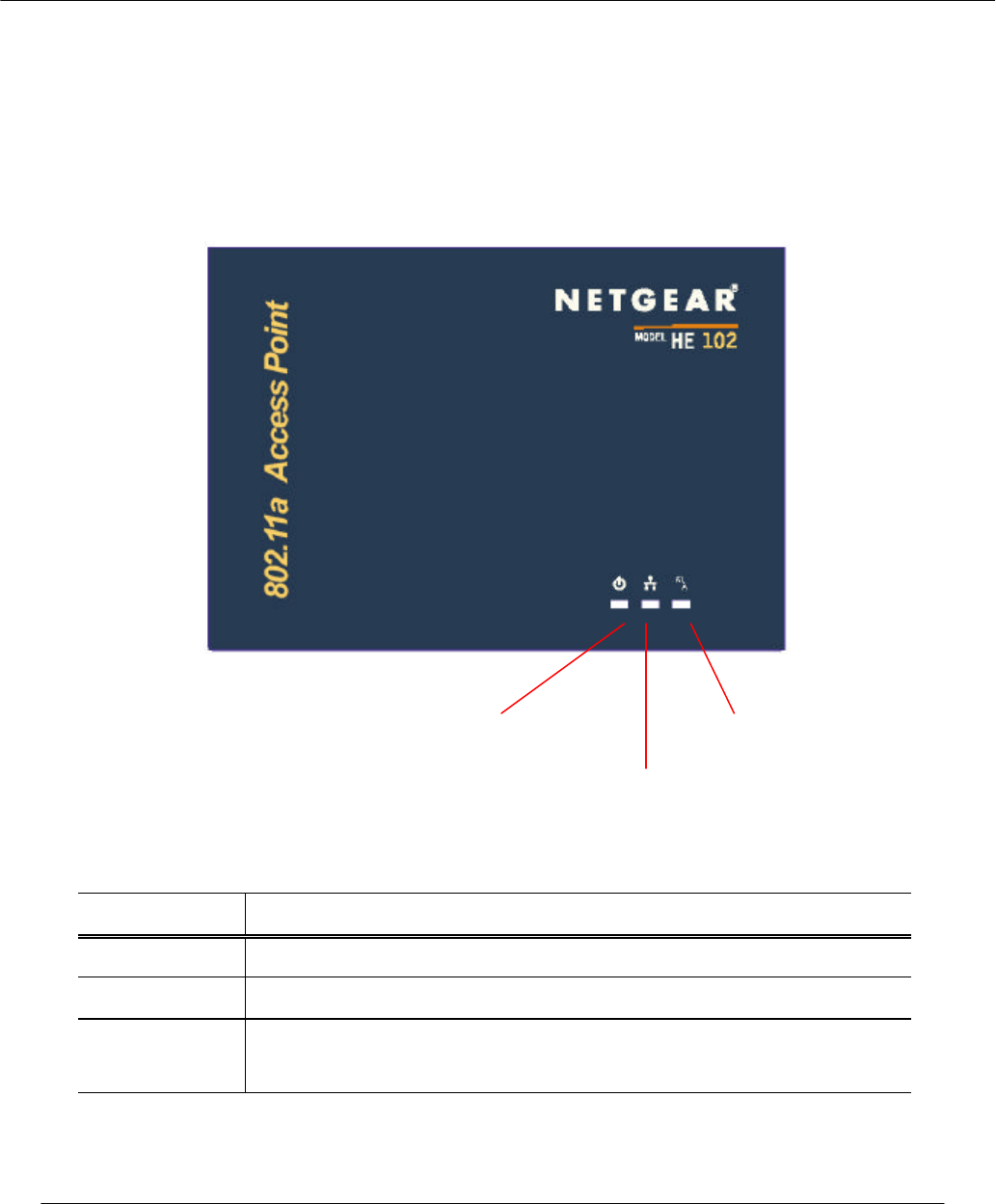
The Model HE102 Access Point (AP) has 3 LED’s, and a pair of side-mounted antennas
that rotate 180° for alternative reception positioning and compact packaging.
Table 1 – LED Functionality
LED 1 Description
Off No Power
On Power On and Ready for Operation
Blink Power On but Not Ready for Operation – at initial power on or reset, this
indicates self-test or software loading; at other times, this indicates a system fault
LED 1 (Power Status)
LED 2 (Ethernet Link)
LED 3 (Wireless Link)

Preliminary
Page 6 • Access point User’s Guide
LED 2 Description
Off No Ethernet Link Detected
Green On 100 Mbps Link Detected but No Activity
Green Blink 100 Mbps Link Activity – blink rate is proportional to activity
Amber On 10 Mbps Link Detected but No Activity
Amber Blink 10 Mbps Link Activity – blink rate is proportional to activity
LED 3 Description
Off Wireless Link Disabled
Very Slow Blink Looking for Network Association
Slow Blink Associated with Network but No Activity
Fast Blink Associated with Network – blink rate is proportional to activity
2.2 Rear View
The rear panel of the AP has a console interface, a RJ-45 Ethernet jack, a restore-to-
default button, and a power supply connector,
RJ
-
45 Ethernet Jack
Restore to
Default Button
Power Supply
Connector

Preliminary
Access Point User’s Guide • Page 7
• The console connector is only used for system configuration during
manufacturing process and should not be connected.
• The RJ-45 Ethernet jack is provided for 10/100 Mbps connectivity to a wired
Ethernet LAN. The Ethernet jack is wired for direct connection to a Ethernet hub
or switch.
• The restore to default push button is to allow the Access Point to be reset back to
the factory default condition in the event that the Access Point is no longer
accessible or controllable through its web-based interface.
• A 3.3 V power supply is provided and is plugged into the power supply connector
of the AP.
Preliminary
Page 8 • Access point User’s Guide
3 AP Network Attachment and Configuration
3.1 AP Network Configuration and Network Boot
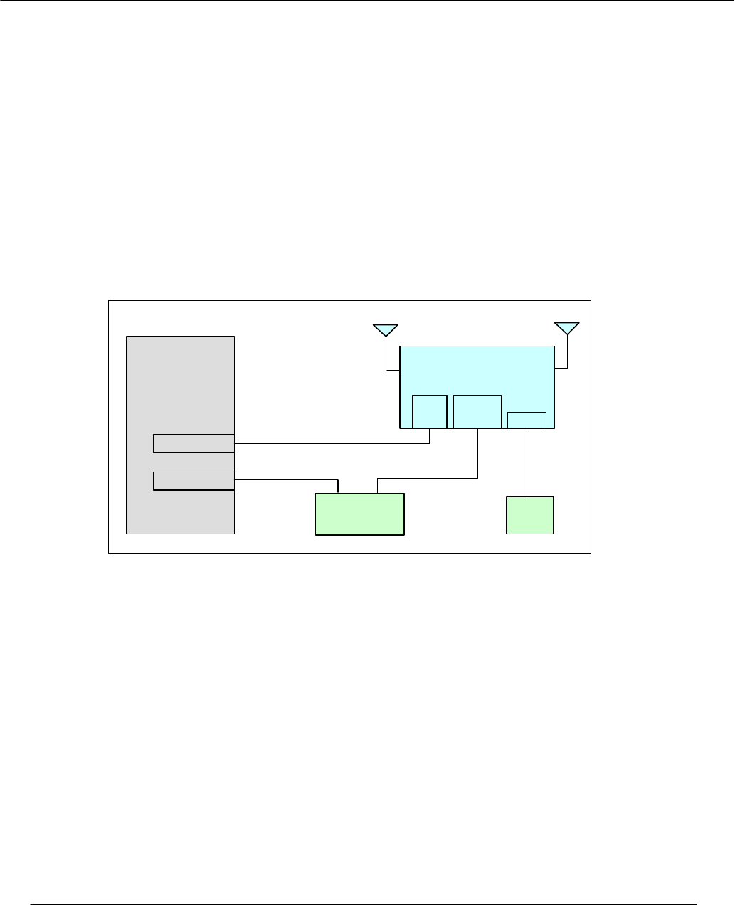
Figure 1 shows an example connection of the AP to a Host PC (HPC). Follow these steps
to establish the physical connections:
1. Connect the AP Ethernet port to the HPC Ethernet card through the Ethernet
hub/switch or an Ethernet crossover cable. An Ethernet switch/hub or crossover
cable is not included.
2. Plug in the 3.3 V power supply adapter (provided by NETGEAR) to the AP
power supply connector.
Figure 1 – Connection Between AP and Host PC
At this point, the Windows-based HPC needs the following configuration steps in order
to control the AP:
1. From the Start menu, choose Settings and open the Network and Dial-up
Connections window.
2. Right-click on the Local Area Network icon in the window, which belongs to the
Ethernet controller that is connected to the AP and select Properties.
Host PC
(HPC)
Ethernet Port
Ethernet Cable
HE102 Access Point
(AP)
Ethernet
Hub/Switch
Ethe
rnet
Port
Power
Power
Supply
Ethernet Cable
Preliminary
Access Point User’s Guide • Page 9
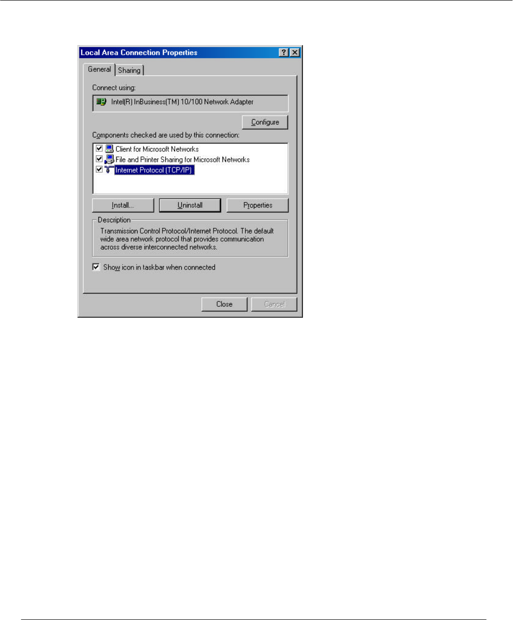
3. Within the Local Area Connection Properties window, choose Internet Protocol
(TCP/IP) and click Properties.
Preliminary
Page 10 • Access point User’s Guide
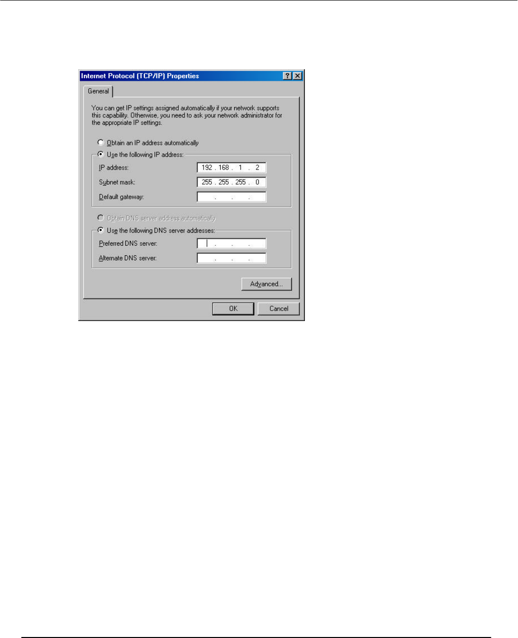
4. Configure the IP address for the Ethernet connection in the Internet Protocol
(TCP/IP) Properties window. Click OK to continue, and close Local Area
Connection Properties. Note that this IP address is used by the HPC to access the
AP through the web-based interface via the Ethernet connection.
Preliminary
Access Point User’s Guide • Page 11
3.2 Configuring the AP through Web Browser
The following procedures show the steps to configure the channel frequency and SSID
using a web browser:
1. Launch a web browser (Netscape Navigator or Internet Explorer are examples of
commonly used web browsers) from the Host PC or other PC on the same IP
subnet as the AP, and enter the IP address that is assigned to the AP as the URL.
This is the “inet on ethernet (e)” value specified during the configuration step in
Section 3.1.1 or Section 3.1.2. The Access Point Web Server page appears.
Preliminary
Page 12 • Access point User’s Guide
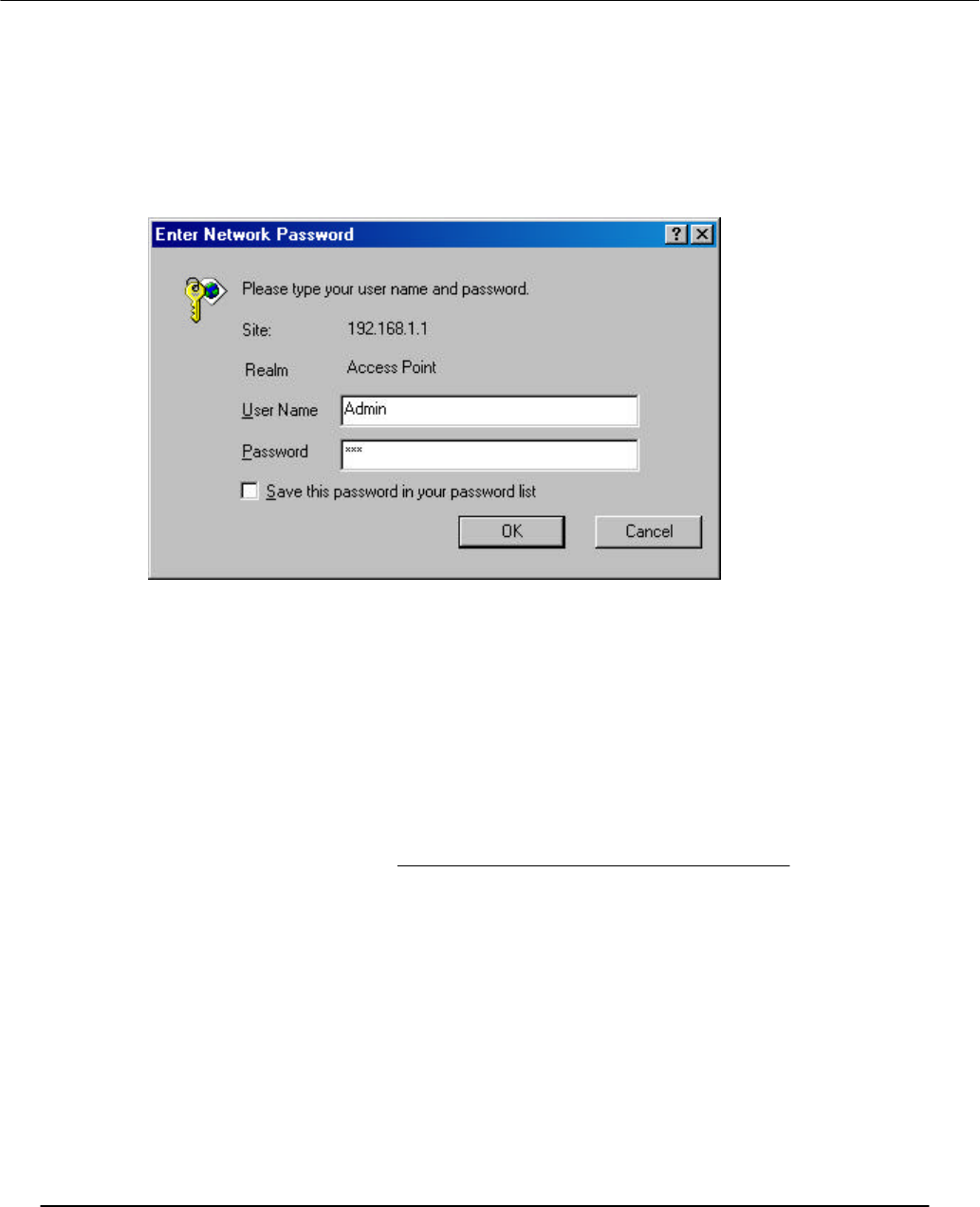
2. Click Setup. A dialog box appears that requests login authorization. When
prompted, enter the following information to log in:
Log in: Admin
Password: 5up
Click OK to complete the login process.
3. After the Setup menu loads, enter the SSID and IEEE Radio Channel that the
stations (STAs) are associating in Infrastructure mode. Click Apply to commit
the changes. At this time you can also change other settings. Refer to Appendix
A for detailed information about each configuration option.
Note that the radio channel is specified using the IEEE 802.11a standard. For
example, channel 48 is the equivalent of 5.240 GHz. The formula below shows
how the channel number is derived:
Channel Number = Channel Frequency (in MHz) – 5000 MHz
5 MHz
Preliminary
Access Point User’s Guide • Page 13
Another new feature added to the AP firmware is the ability to control Transmit
Power parameter. This feature can be used to decrease the transmit power, and
therefore, reduce the range of the radio. In this operation mode, more than one
AP with the same channel frequency can exist in the same location (as long as the
ranges of these APs can cover are not overlapped each other).
Preliminary
Page 14 • Access point User’s Guide
4. Optionally, you can also set up Wired Equivalent Privacy (WEP) for security
purposes. To set up WEP, click WEP and the configuration screen appears.
Refer to Appendix A for a detailed explanation of the WEP configuration options.
Click Apply to save the settings.
Note that the Un-Encrypted Frames filter option (previously available in release
1.0) is now removed.
Preliminary
Access Point User’s Guide • Page 16
Appendix A—AP Web Server
Introduction
You can configure the AP through a web browser interface to the AP web server. The
web server resides in the AP and is accessible from any STA that is connected to the AP
Infrastructure network.
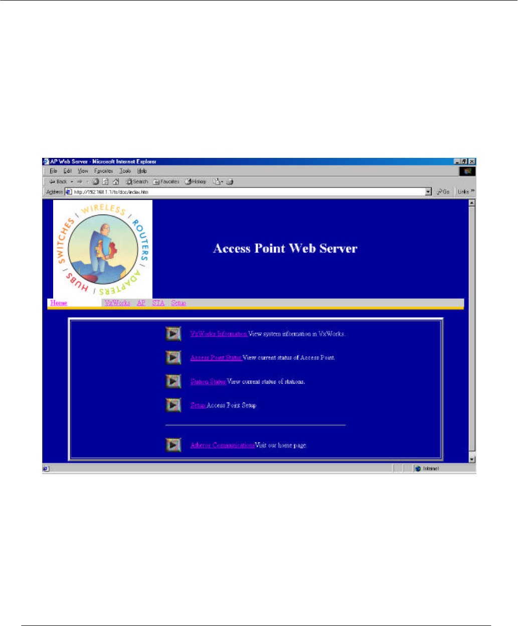
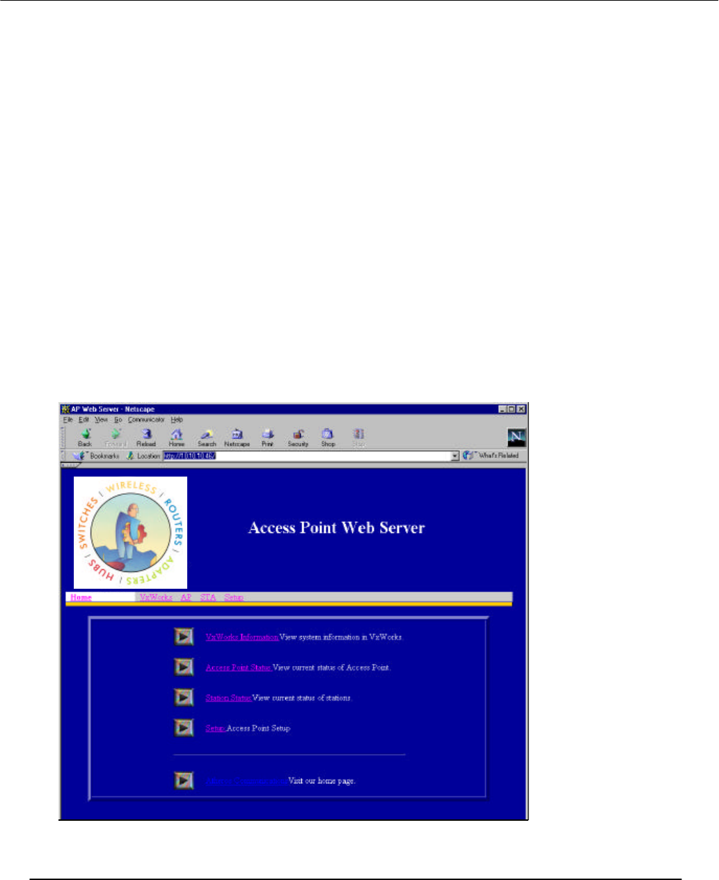
Accessing the AP Web Server
To access the AP web server, use the IP address of the AP as the URL address, for
example http://192.168.1.1. The web server home page contains several hyperlinks that
provide viewing of the system information, status of the AP and associated stations, and
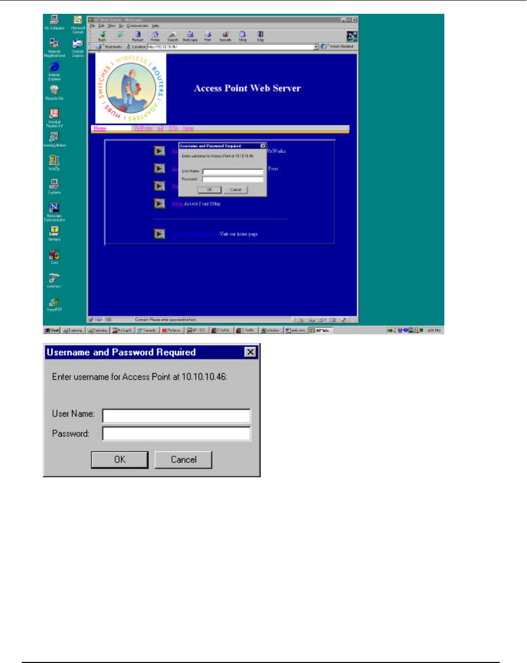
configuration parameters of the AP. On the initial entry into the AP web server (click on
hyperlink) a popup window appears prompting for a username and password. Enter the
username and password, and click “OK” to enter the AP web server.
If you want to receive warning messages when configuring the AP, enable JavaScript on
the web browser. Otherwise, no warnings are issued.
Preliminary
Access Point User’s Guide • Page 17

Preliminary
Access Point User’s Guide • Page 18
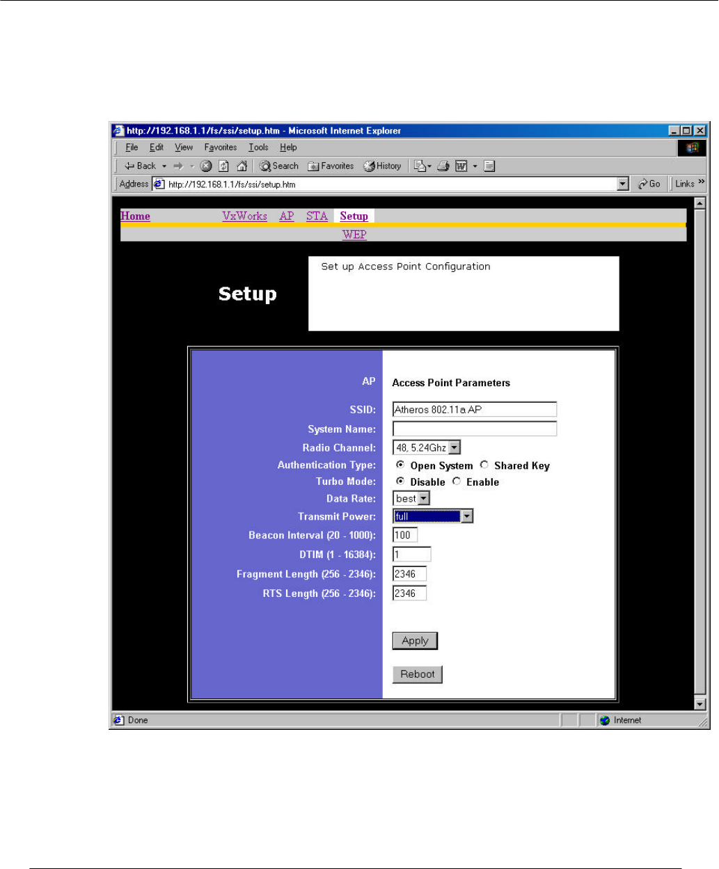
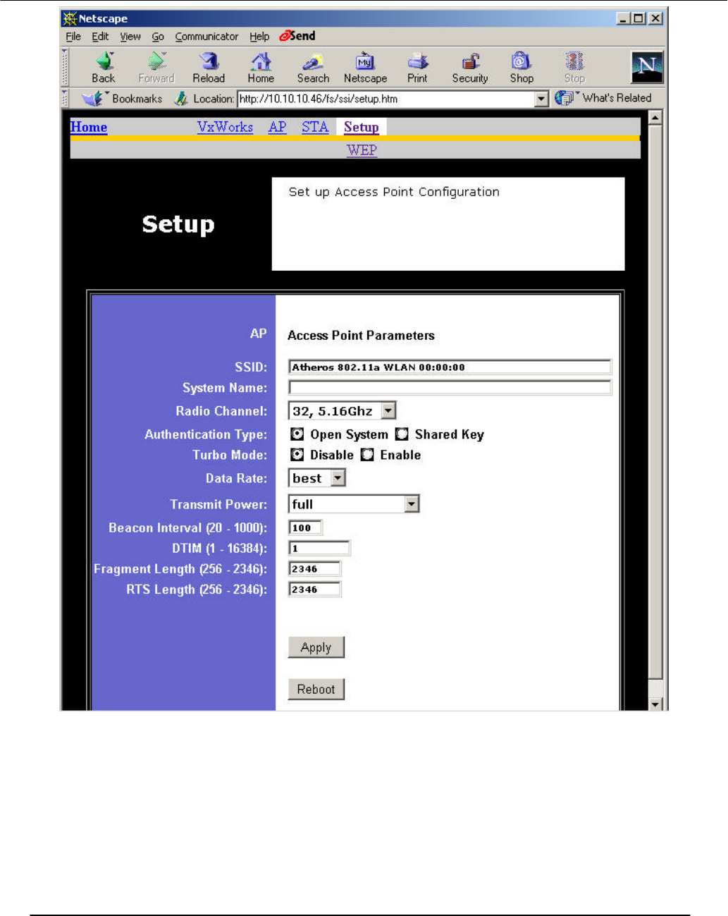
Setup
Click the Setup hyperlink from the AP Web Server home page to change AP
configuration parameters. This page displays the current configuration of the AP. If you
modify the configuration parameters, you must click Apply to save the changes. The new
configuration is not in effect until you reboot the AP. Click Reboot to reboot the AP. The
web browser loses connectivity with the AP web server as the AP reboots. To establish a
network connection to the rebooted AP, wait until the AP has completed rebooting, and
then navigate to the web server home page (by clicking the Home hyperlink) to resume
communication with the AP web server.
Preliminary
Access Point User’s Guide • Page 19

Preliminary
Access Point User’s Guide • Page 20
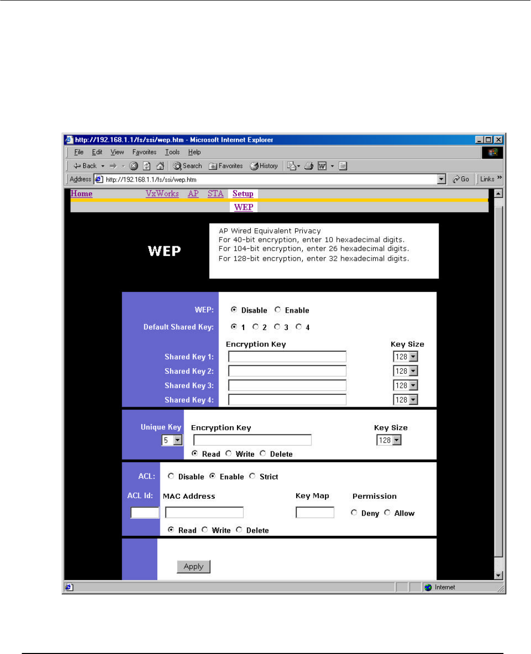
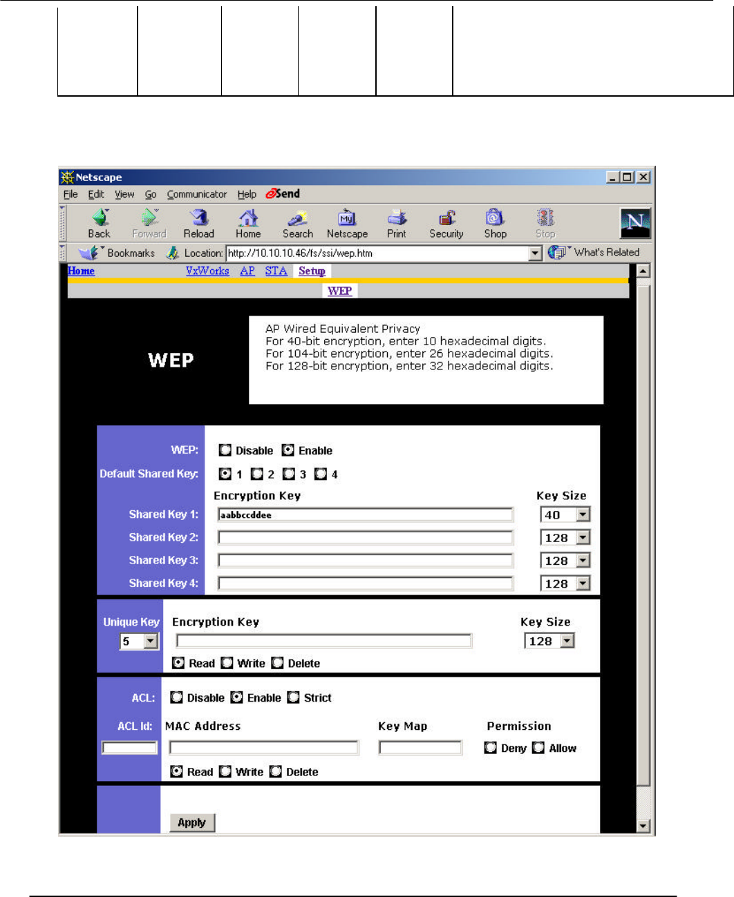
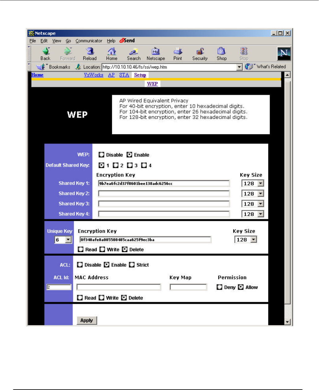
WEP
Click the WEP hyperlink to configure the WEP keys.
The configurable options of the WEP page provide the ability to:
• Enable and disable WEP
• Select the default shared WEP key
• Specify the shared and unique WEP keys
• Enable, disable, restrict, and configure the ACL
Refer to the following table for examples of WEP configurations on the AP and the STA.
WEP: Disable WEP is disabled. Any STA can access to the
network
WEP: Enable
ACL Shared Key
ACL MAC
address Key Map Permission
WEP
No Disable No No No WEP is disabled. Any STA can access to the
network
Yes Disable No No No Only STA with matched shared key can
access to the network
Yes Enable Yes No Allow 1. STA with matched MAC ID can access to
the network
2. Any STAs with matched shared key are
also allowed to access to the network
Yes Enable No Unique key
Allow 1. STA with matched unique key can access
to the network
2. Any STAs with matched shared key are
also allowed to access to the network
Yes Enable Yes Unique key
Allow 1. STA with matched MAC ID and matched
unique key can access to the network
2. Any STAs with matched shared key are
also allowed to access to the network
x Enable Yes No Deny STA with the matched MAC ID is blocked
from accessing the network
x Enable No Unique key
Deny STA with the matched unique key is blocked
from accessing the network
x Enable Yes Unique key
Deny STA with the matched MAC ID and unique
key is blocked from accessing the network
Preliminary
Access Point User’s Guide • Page 21
Yes Strict x x x 1. Only STA with MAC ID and/or unique key
matched to the setup in ACL can access to
the network.
2. The STAs with only shared key are
blocked from accessing the network.
After entering or modifying the WEP configuration, you must click Apply to save the
changes.
Preliminary
Access Point User’s Guide • Page 22
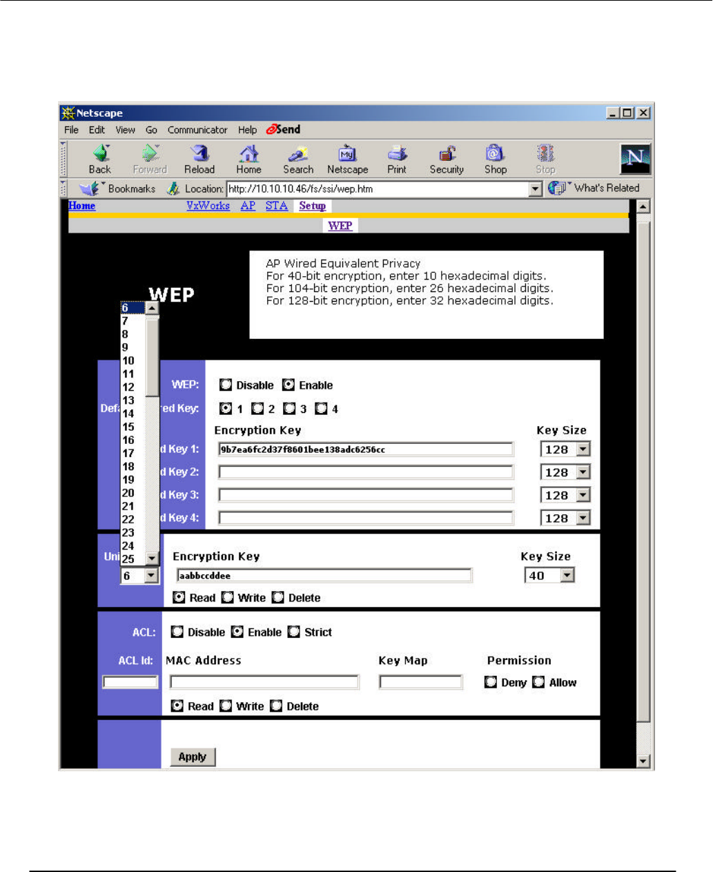
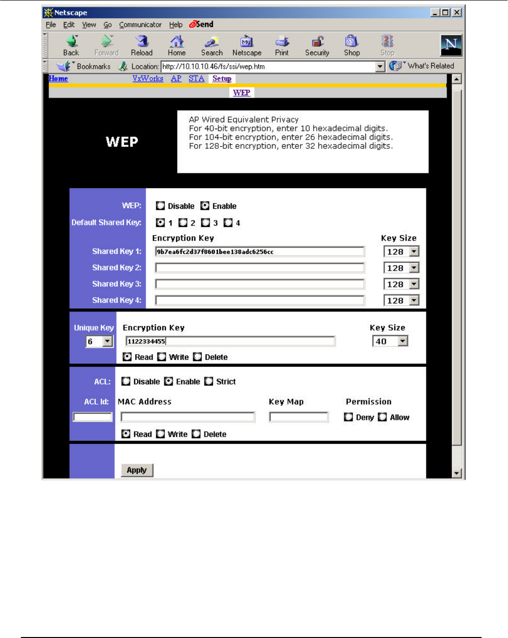
To view the configuration of a unique key, use the pull down menu to select the unique
key ID, select Read inside the Unique Key frame, and then click Apply to view the
unique key. In this example, unique key ID 6 is selected. The next example shows the
results.
Preliminary
Access Point User’s Guide • Page 23
Preliminary
Access Point User’s Guide • Page 24
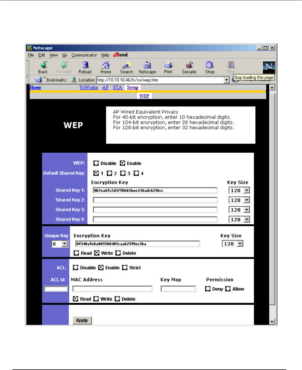
To make changes, select Write, enter the key changes, select the appropriate key size,
select a unique key ID, and click Apply. Use the same procedure to add new unique keys.
Note that the unique key ID starts from 5 and ends at 64. A total of 60 unique keys can
be stored in the AP.
Preliminary
Access Point User’s Guide • Page 25
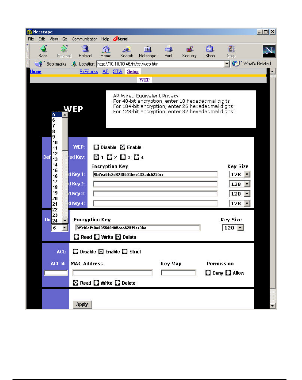
To delete a unique key, select Delete, use the pull down menu to select the unique key ID
that contains the unique key you want to delete, and click Apply.
Preliminary
Access Point User’s Guide • Page 26
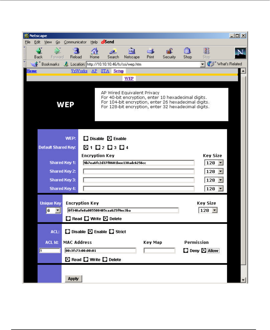
To view the ACL list, select Read inside the ACL frame, enter the ACL ID to be viewed,
and click Apply. In this example, ACL ID 1 is selected and displayed, and specifies that
MAC address 00:3f:73:00:00:01 is allowed access.
Preliminary
Access Point User’s Guide • Page 27
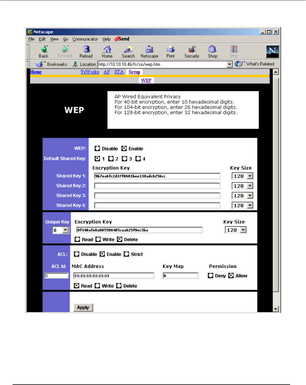
In this example, ACL ID 3 is selected and displayed, and specifies that MAC address
11:11:11:11:11:11 is allowed access with unique key 6.
Preliminary
Access Point User’s Guide • Page 28
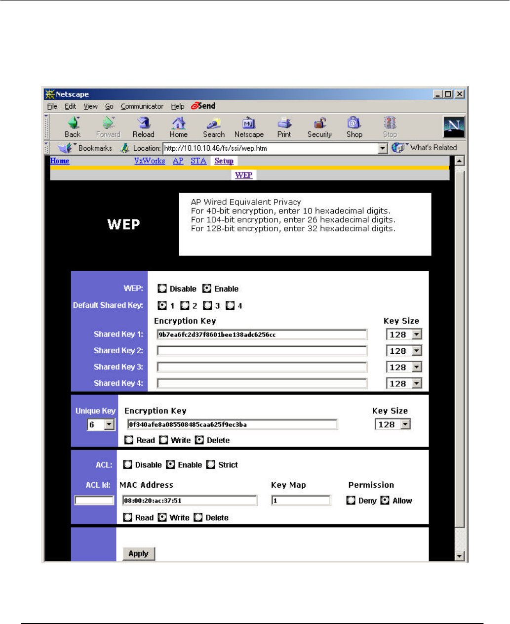
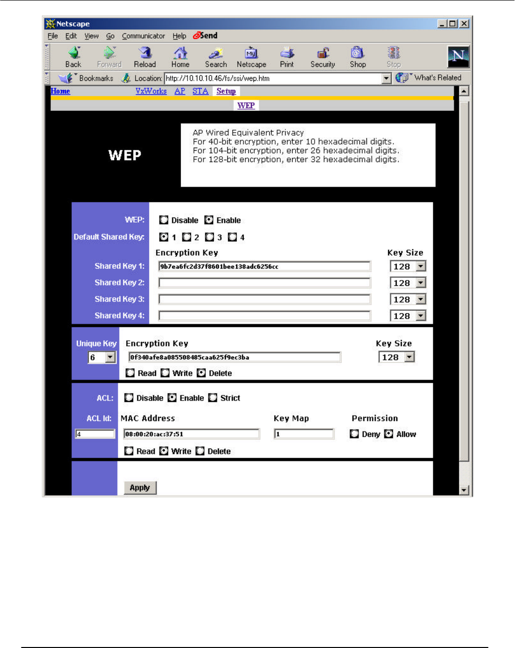
To add a new ACL entry, select Write, enter the new MAC address, enter key ID
(if needed), select either Deny or Allow, and click Apply to save the changes. In this
example, the new ACL entry has the MAC address 08:00:20:ac:37:51 using shared key 1
to allow access. The next example shows that the changes are accepted and ACL ID 4
(the next available ACL ID) is automatically assigned.
Preliminary
Access Point User’s Guide • Page 29
Preliminary
Access Point User’s Guide • Page 30
To delete an ACL entry, select Delete, enter the ACL ID to be deleted, and click Apply.
In this example, ACL ID 2 is deleted.