Netgear orporated NM7371 CDMA/LTE Mini-Card Module User Manual NM7371 HWIG FCC
Netgear Incorporated CDMA/LTE Mini-Card Module NM7371 HWIG FCC
UserManual.wiki
>
Netgear orporated
>
NM7371 User Manual
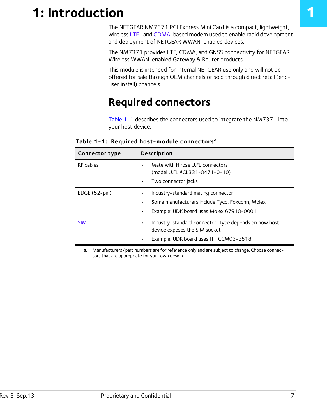
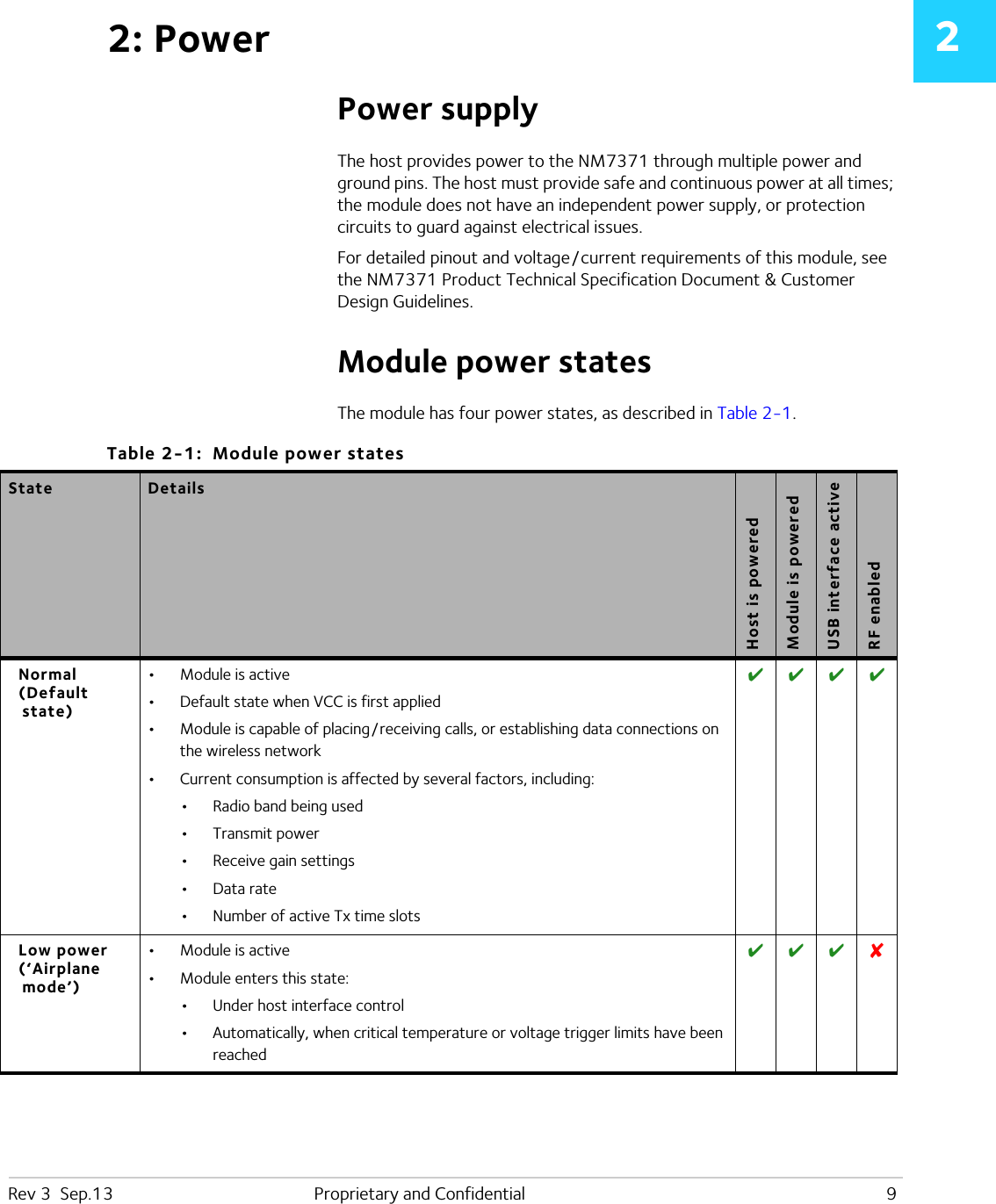
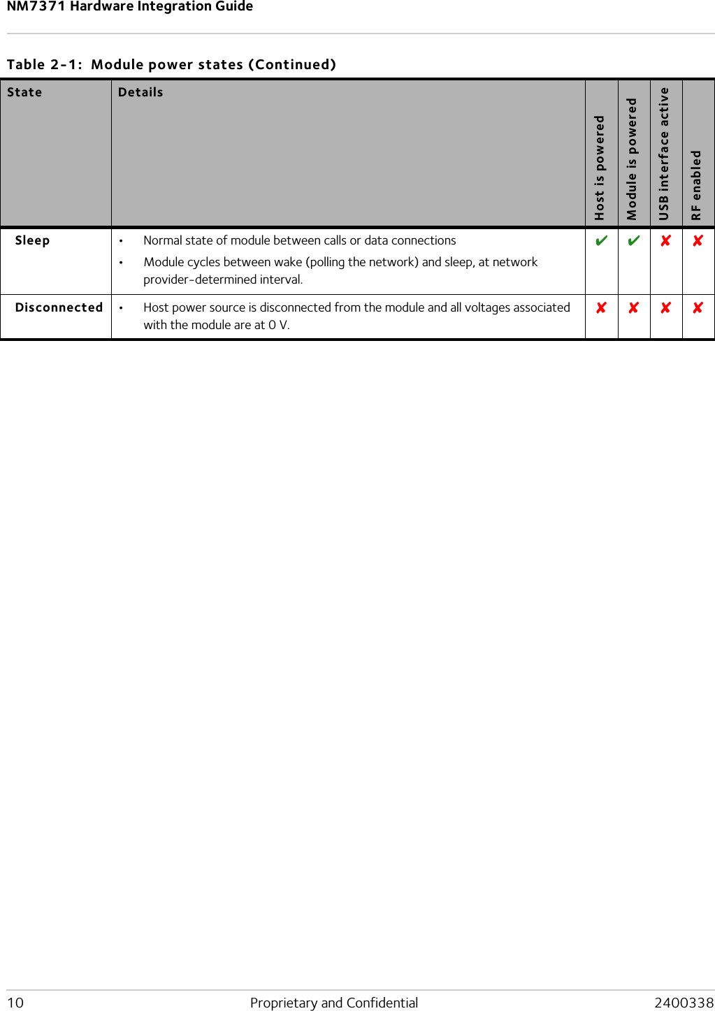
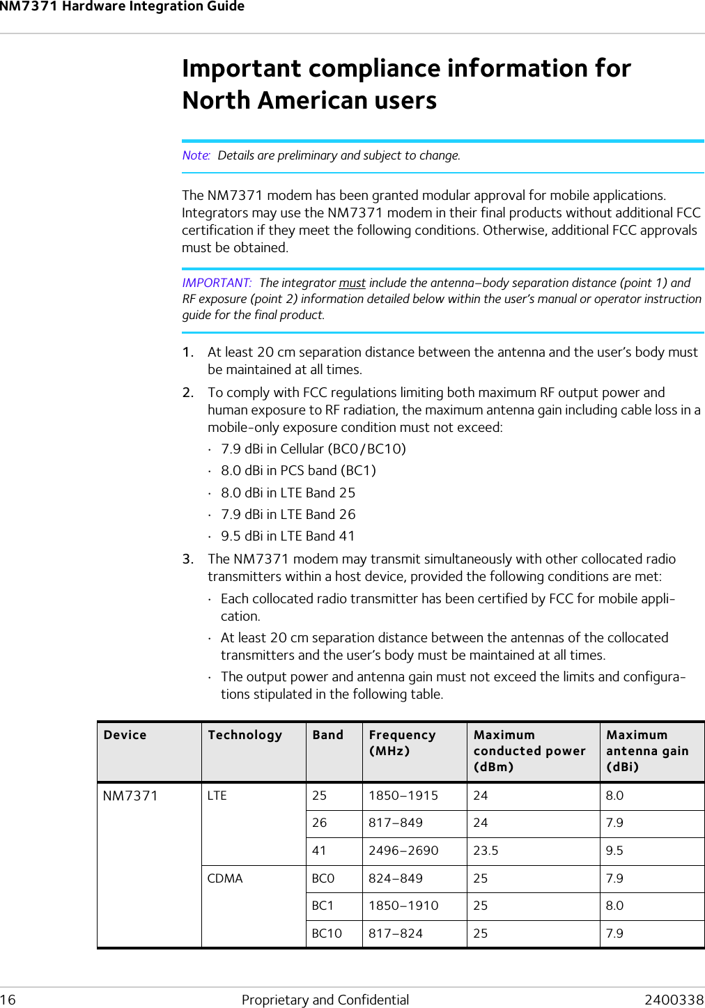
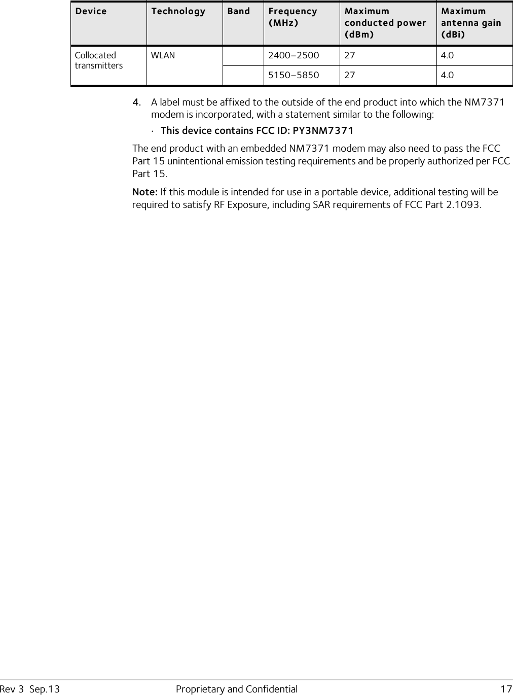
Integration Guide
Navigation menu
Upload a User Manual
Namespaces
Wiki Guide
HTML
PDF
Info
Views
User Manual
Discussion / Help
Navigation