Netgear orporated NM7371 CDMA/LTE Mini-Card Module User Manual NM7371 HWIG FCC
Netgear Incorporated CDMA/LTE Mini-Card Module NM7371 HWIG FCC
Integration Guide

NM7371
Hardware Integration Guide
2400338 Rev 3

Preface
Rev 3 Sep.13 Proprietary and Confidential 3
Important
Notice
Due to the nature of wireless communications, transmission and reception of data can
never be guaranteed. Data may be delayed, corrupted (i.e., have errors) or be totally
lost. Although significant delays or losses of data are rare when wireless devices such as
the NETGEAR® modem are used in a normal manner with a well-constructed network,
the NETGEAR modem should not be used in situations where failure to transmit or
receive data could result in damage of any kind to the user or any other party, including
but not limited to personal injury, death, or loss of property. NETGEAR accepts no
responsibility for damages of any kind resulting from delays or errors in data
transmitted or received using the NETGEAR modem, or for failure of the NETGEAR
modem to transmit or receive such data.
Safety and
Hazards
Do not operate the NETGEAR modem in areas where blasting is in progress, where
explosive atmospheres may be present, near medical equipment, near life support
equipment, or any equipment which may be susceptible to any form of radio
interference. In such areas, the NETGEAR modem MUST BE POWERED OFF. The
NETGEAR modem can transmit signals that could interfere with this equipment.
Do not operate the NETGEAR modem in any aircraft, whether the aircraft is on the
ground or in flight. In aircraft, the NETGEAR modem MUST BE POWERED OFF. When
operating, the NETGEAR modem can transmit signals that could interfere with various
onboard systems.
The driver or operator of any vehicle should not operate the NETGEAR modem while in
control of a vehicle. Doing so will detract from the driver or operator's control and
operation of that vehicle. In some states and provinces, operating such communications
devices while in control of a vehicle is an offence.
Limitation of
Liability
The information in this manual is subject to change without notice and does not
represent a commitment on the part of NETGEAR. NETGEAR AND ITS AFFILIATES
SPECIFICALLY DISCLAIM LIABILITY FOR ANY AND ALL DIRECT, INDIRECT, SPECIAL,
GENERAL, INCIDENTAL, CONSEQUENTIAL, PUNITIVE OR EXEMPLARY DAMAGES
INCLUDING, BUT NOT LIMITED TO, LOSS OF PROFITS OR REVENUE OR ANTICIPATED
PROFITS OR REVENUE ARISING OUT OF THE USE OR INABILITY TO USE ANY NETGEAR
PRODUCT, EVEN IF NETGEAR AND/OR ITS AFFILIATES HAS BEEN ADVISED OF THE
POSSIBILITY OF SUCH DAMAGES OR THEY ARE FORESEEABLE OR FOR CLAIMS BY ANY
THIRD PARTY.
Notwithstanding the foregoing, in no event shall NETGEAR and/or its affiliates
aggregate liability arising under or in connection with the NETGEAR product, regardless
of the number of events, occurrences, or claims giving rise to liability, be in excess of
the price paid by the purchaser for the NETGEAR product.

NM7371 Hardware Integration Guide
4 Proprietary and Confidential 2400338
Patents This product may contain technology developed by or for NETGEAR Inc. This product
includes technology licensed from QUALCOMM®.
Copyright ©2013 NETGEAR, Inc. All rights reserved.
Trademarks NETGEAR, the NETGEAR logo, AirCard, and Watcher are trademarks of NETGEAR, Inc. in
the United States and/or other countries. Other brand names mentioned herein are for
identification purposes only and may be trademarks of their respective holder(s).
Windows® and Windows Vista® are registered trademarks of Microsoft Corporation.
Macintosh® and Mac OS X® are registered trademarks of Apple Inc., registered in the
U.S. and other countries.
QUALCOMM® is a registered trademark of QUALCOMM Incorporated. Used under
license.
Other trademarks are the property of their respective owners.
Information is subject to change without notice.

Rev 3 Sep.13 Proprietary and Confidential 5
Contents
Introduction . . . . . . . . . . . . . . . . . . . . . . . . . . . . . . . . . . . . . . . . . . . . . . . . . . . . . . . .7
Required connectors. . . . . . . . . . . . . . . . . . . . . . . . . . . . . . . . . . . . . . . . . . . . . . . . . . . . . . . 7
Power . . . . . . . . . . . . . . . . . . . . . . . . . . . . . . . . . . . . . . . . . . . . . . . . . . . . . . . . . . . . .9
Power supply . . . . . . . . . . . . . . . . . . . . . . . . . . . . . . . . . . . . . . . . . . . . . . . . . . . . . . . . . . . . . 9
Module power states . . . . . . . . . . . . . . . . . . . . . . . . . . . . . . . . . . . . . . . . . . . . . . . . . . . . . . 9
RF Specifications . . . . . . . . . . . . . . . . . . . . . . . . . . . . . . . . . . . . . . . . . . . . . . . . . . 11
RF connections. . . . . . . . . . . . . . . . . . . . . . . . . . . . . . . . . . . . . . . . . . . . . . . . . . . . . . . . . . . 11
Shielding . . . . . . . . . . . . . . . . . . . . . . . . . . . . . . . . . . . . . . . . . . . . . . . . . . . . . . . . . . . . 11
Antenna . . . . . . . . . . . . . . . . . . . . . . . . . . . . . . . . . . . . . . . . . . . . . . . . . . . . . . . . . . . . . 11
Choosing the correct antenna cabling . . . . . . . . . . . . . . . . . . . . . . . . . . . . . . . . 11
Determining the antenna’s location . . . . . . . . . . . . . . . . . . . . . . . . . . . . . . . . . . 11
Ground connection . . . . . . . . . . . . . . . . . . . . . . . . . . . . . . . . . . . . . . . . . . . . . . . . . . . . . . . 12
Interference and sensitivity. . . . . . . . . . . . . . . . . . . . . . . . . . . . . . . . . . . . . . . . . . . . . . . . 12
Interference from other wireless devices . . . . . . . . . . . . . . . . . . . . . . . . . . . . . . . . 12
Host-generated RF interference . . . . . . . . . . . . . . . . . . . . . . . . . . . . . . . . . . . . . . . 13
Methods to mitigate decreased Rx performance . . . . . . . . . . . . . . . . . . . . . . . . . 13
Radiated Spurious Emissions (RSE) . . . . . . . . . . . . . . . . . . . . . . . . . . . . . . . . . . . . . 13
Regulatory Compliance and Industry Certfications . . . . . . . . . . . . . . . . . . . . . . 15
Important notice . . . . . . . . . . . . . . . . . . . . . . . . . . . . . . . . . . . . . . . . . . . . . . . . . . . . . . . . . 15
Safety and hazards . . . . . . . . . . . . . . . . . . . . . . . . . . . . . . . . . . . . . . . . . . . . . . . . . . . . . . . 15
Important compliance information for North American users . . . . . . . . . . . . . . . . . . 16
Acronyms . . . . . . . . . . . . . . . . . . . . . . . . . . . . . . . . . . . . . . . . . . . . . . . . . . . . . . . . 19

NM7371 Hardware Integration Guide
6 Proprietary and Confidential 2400338

Rev 3 Sep.13 Proprietary and Confidential 7
1
1: Introduction
The NETGEAR NM7371 PCI Express Mini Card is a compact, lightweight,
wireless LTE- and CDMA-based modem used to enable rapid development
and deployment of NETGEAR WWAN-enabled devices.
The NM7371 provides LTE, CDMA, and GNSS connectivity for NETGEAR
Wireless WWAN-enabled Gateway & Router products.
This module is intended for internal NETGEAR use only and will not be
offered for sale through OEM channels or sold through direct retail (end-
user install) channels.
Required connectors
Table 1-1 describes the connectors used to integrate the NM7371 into
your host device.
Table 1-1: Required host-module connectorsa
Connector type Description
RF cables •Mate with Hirose U.FL connectors
(model U.FL #CL331-0471-0-10)
•Two connector jacks
EDGE (52-pin) •Industry-standard mating connector
•Some manufacturers include Tyco, Foxconn, Molex
•Example: UDK board uses Molex 67910-0001
SIM •Industry-standard connector. Type depends on how host
device exposes the SIM socket
•Example: UDK board uses ITT CCM03-3518
a. Manufacturers / part numbers are for reference only and are subject to change. Choose connec-
tors that are appropriate for your own design.

NM7371 Hardware Integration Guide
8 Proprietary and Confidential 2400338

Rev 3 Sep.13 Proprietary and Confidential 9
2
2: Power
Power supply
The host provides power to the NM7371 through multiple power and
ground pins. The host must provide safe and continuous power at all times;
the module does not have an independent power supply, or protection
circuits to guard against electrical issues.
For detailed pinout and voltage / current requirements of this module, see
the NM7371 Product Technical Specification Document & Customer
Design Guidelines.
Module power states
The module has four power states, as described in Table 2-1.
Table 2-1: Module power states
State Details
Host is powered
Module is powered
USB interface active
RF enabled
Normal
(Default
state)
•Module is active
•Default state when VCC is first applied
•Module is capable of placing / receiving calls, or establishing data connections on
the wireless network
•Current consumption is affected by several factors, including:
•Radio band being used
•Transmit power
•Receive gain settings
•Data rate
•Number of active Tx time slots
Low power
(‘Airplane
mode’)
•Module is active
•Module enters this state:
•Under host interface control
•Automatically, when critical temperature or voltage trigger limits have been
reached

NM7371 Hardware Integration Guide
10 Proprietary and Confidential 2400338
Sleep •Normal state of module between calls or data connections
•Module cycles between wake (polling the network) and sleep, at network
provider-determined interval.
Disconnected •Host power source is disconnected from the module and all voltages associated
with the module are at 0 V.
Table 2-1: Module power states (Continued)
State Details
Host is powered
Module is powered
USB interface active
RF enabled

Rev 3 Sep.13 Proprietary and Confidential 11
3
3: RF Specifications
The NM7371 operates on the frequency bands listed below.
RF connections
When attaching antennas to the module:
Note: To disconnect the
antenna, make sure you use
the Hirose U.FL connector
removal tool
(P / N UFL-LP-N-2(01)) to
prevent damage to the
module or coaxial cable
assembly.
•Use Hirose U.FL connectors (3 mm x 3 mm, low profile; model
U.FL #CL331-0471-0-10) to attach antennas to the module’s
connection points.
•Match coaxial connections between the module and antenna to 50 .
•Minimize RF cable losses to the antenna; the recommended maximum
cable loss for antenna cabling is 0.5 dB.
•To ensure best thermal performance, if possible use the mounting
holes to attach (ground) the device to the main PCB ground or a metal
chassis.
Note: If the antenna connection is shorted or open, the modem will not sustain
permanent damage.
Shielding
The module is fully shielded to protect against EMI and must not be
removed.
Antenna
When selecting antennas for use with NM7371, refer to MPE
requirements and limitations defined within the FCC application and
available on the FCC website.
Choosing the correct antenna cabling
When matching antennas and cabling:
•The antenna (and associated circuitry) should have a nominal
impedance of 50 with a return loss of better than 10 dB across
each frequency band of operation.
Determining the antenna’s location
When deciding where to put the antennas:
•Antenna location may affect RF performance. Although the module is
shielded to prevent interference in most applications, the placement

NM7371 Hardware Integration Guide
12 Proprietary and Confidential 2400338
of the antenna is still very important — if the host device is insufficiently shielded,
high levels of broadband or spurious noise can degrade the module’s performance.
•Connecting cables between the module and the antenna must have 50
impedance. If the impedance of the module is mismatched, RF performance is
reduced significantly.
•Antenna cables should be routed, if possible, away from noise sources (switching
power supplies, LCD assemblies, etc.). If the cables are near the noise sources, the
noise may be coupled into the RF cable and into the antenna.
Ground connection
When connecting the module to system ground:
•Prevent noise leakage by establishing a very good ground connection to the module
through the host connector.
•Connect to system ground using the two mounting holes at the top of the module.
•Minimize ground noise leakage into the RF.
Depending on the host board design, noise could potentially be coupled to the
module from the host board. This is mainly an issue for host designs that have
signals traveling along the length of the module, or circuitry operating at both ends
of the module interconnects.
Interference and sensitivity
Several interference sources can affect the module’s RF performance (RF desense).
Common sources include power supply noise and device-generated RF.
RF desense can be addressed through a combination of mitigation techniques (Methods
to mitigate decreased Rx performance on page 13) and radiated sensitivity
measurement.
Note: The NM7371 is based on ZIF (Zero Intermediate Frequency) technologies. When
performing EMC (Electromagnetic Compatibility) tests, there are no IF (Intermediate Frequency)
components from the module to consider.
Interference from other wireless devices
Wireless devices operating inside the host device can cause interference that affects
the module.
To determine the most suitable locations for antennas on your host device, evaluate
each wireless device’s radio system, considering the following:
•Any harmonics, sub-harmonics, or cross-products of signals generated by wireless
devices that fall in the module’s Rx range may cause spurious response, resulting in
decreased Rx performance.
•The Tx power and corresponding broadband noise of other wireless devices may
overload or increase the noise floor of the module’s receiver, resulting in Rx
desense.

Rev 3 Sep.13 Proprietary and Confidential 13
The severity of this interference depends on the closeness of the other antennas to the
module’s antenna. To determine suitable locations for each wireless device’s antenna,
thoroughly evaluate your host device’s design.
Host-generated RF interference
All electronic computing devices generate RF interference that can negatively affect the
receive sensitivity of the module.
Proximity of host electronics to the antenna in wireless devices can contribute to
decreased Rx performance. Components that are most likely to cause this include:
•Microprocessor and memory
•Display panel and display drivers
•Switching-mode power supplies
Methods to mitigate decreased Rx performance
It is important to investigate sources of localized interference early in the design cycle.
To reduce the effect of device-generated RF on Rx performance:
•Put the antenna as far as possible from sources of interference. The drawback is
that the module may be less convenient to use.
•Shield the host device. The module itself is well shielded to avoid external inter-
ference. However, the antenna cannot be shielded for obvious reasons. In most
instances, it is necessary to employ shielding on the components of the host device
(such as the main processor and parallel bus) that have the highest RF emissions.
•Filter out unwanted high-order harmonic energy by using discrete filtering on low
frequency lines.
•Form shielding layers around high-speed clock traces by using multi-layer PCBs.
•Route antenna cables away from noise sources.
Radiated Spurious Emissions (RSE)
When designing an antenna for use with NETGEAR embedded modules, the host device
with a NETGEAR embedded module must satisfy the radiated spurious emissions (RSE)
test cases described in 3GPP2 (CDMA) and 3GPP (LTE).
Note that antenna impedance affects radiated emissions, which must be compared
against the conducted 50-ohm emissions baseline. (NETGEAR embedded modules meet
the 50-ohm conducted emissions requirement.)

NM7371 Hardware Integration Guide
14 Proprietary and Confidential 2400338

Rev 3 Sep.13 Proprietary and Confidential 15
4
4: Regulatory Compliance and Industry
Certfications
This module is designed to meet, and upon commercial release, will meet
the requirements of the following regulatory bodies and regulations,
where applicable:
•Federal Communications Commission (FCC) of the United States
Important notice
Because of the nature of wireless communications, transmission and
reception of data can never be guaranteed. Data may be delayed,
corrupted (i.e., have errors) or be totally lost. Although significant delays
or losses of data are rare when wireless devices such as the NETGEAR
modem are used in a normal manner with a well-constructed network, the
NETGEAR modem should not be used in situations where failure to
transmit or receive data could result in damage of any kind to the user or
any other party, including but not limited to personal injury, death, or loss
of property. NETGEAR and its affiliates accept no responsibility for
damages of any kind resulting from delays or errors in data transmitted or
received using the NETGEAR modem, or for failure of the NETGEAR
modem to transmit or receive such data.
Safety and hazards
Do not operate your NM7371 modem:
•In areas where blasting is in progress
•Where explosive atmospheres may be present including refuelling
points, fuel depots, and chemical plants
•Near medical equipment, life support equipment, or any equipment
which may be susceptible to any form of radio interference. In such
areas, the NM7371 modem MUST BE POWERED OFF. Otherwise,
the NM7371 modem can transmit signals that could interfere with
this equipment.
In an aircraft, the NM7371 modem MUST BE POWERED OFF. Otherwise,
the NM7371 modem can transmit signals that could interfere with various
onboard systems and may be dangerous to the operation of the aircraft or
disrupt the cellular network.
NM7371 Hardware Integration Guide
16 Proprietary and Confidential 2400338
Important compliance information for
North American users
Note: Details are preliminary and subject to change.
The NM7371 modem has been granted modular approval for mobile applications.
Integrators may use the NM7371 modem in their final products without additional FCC
certification if they meet the following conditions. Otherwise, additional FCC approvals
must be obtained.
IMPORTANT: The integrator must include the antenna–body separation distance (point 1) and
RF exposure (point 2) information detailed below within the user’s manual or operator instruction
guide for the final product.
1. At least 20 cm separation distance between the antenna and the user’s body must
be maintained at all times.
2. To comply with FCC regulations limiting both maximum RF output power and
human exposure to RF radiation, the maximum antenna gain including cable loss in a
mobile-only exposure condition must not exceed:
·7.9 dBi in Cellular (BC0 / BC10)
·8.0 dBi in PCS band (BC1)
·8.0 dBi in LTE Band 25
·7.9 dBi in LTE Band 26
·9.5 dBi in LTE Band 41
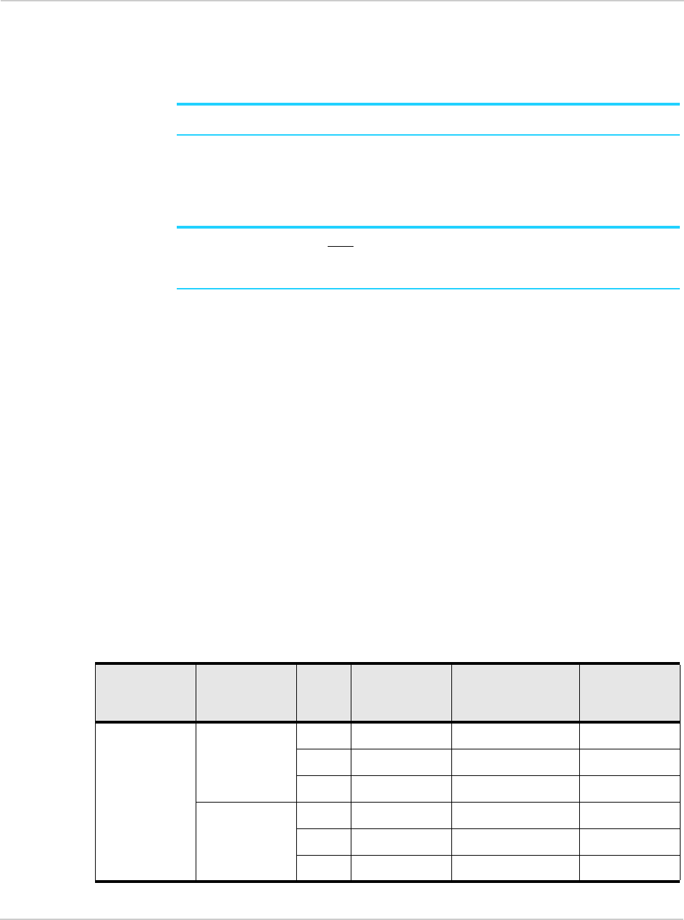
3. The NM7371 modem may transmit simultaneously with other collocated radio
transmitters within a host device, provided the following conditions are met:
·Each collocated radio transmitter has been certified by FCC for mobile appli-
cation.
·At least 20 cm separation distance between the antennas of the collocated
transmitters and the user’s body must be maintained at all times.
·The output power and antenna gain must not exceed the limits and configura-
tions stipulated in the following table.
Device Technology Band Frequency
(MHz)
Maximum
conducted power
(dBm)
Maximum
antenna gain
(dBi)
NM7371 LTE 25 1850–1915 24 8.0
26 817–849 24 7.9
41 2496–2690 23.5 9.5
CDMA BC0 824–849 25 7.9
BC1 1850–1910 25 8.0
BC10 817–824 25 7.9

Rev 3 Sep.13 Proprietary and Confidential 17
4. A label must be affixed to the outside of the end product into which the NM7371
modem is incorporated, with a statement similar to the following:
·This device contains FCC ID: PY3NM7371
The end product with an embedded NM7371 modem may also need to pass the FCC
Part 15 unintentional emission testing requirements and be properly authorized per FCC
Part 15.
Note: If this module is intended for use in a portable device, additional testing will be
required to satisfy RF Exposure, including SAR requirements of FCC Part 2.1093.
Collocated
transmitters
WLAN 2400–2500 27 4.0
5150–5850 27 4.0
Device Technology Band Frequency
(MHz)
Maximum
conducted power
(dBm)
Maximum
antenna gain
(dBi)

NM7371 Hardware Integration Guide
18 Proprietary and Confidential 2400338

Rev 3 Sep.13 Proprietary and Confidential 19
A
A: Acronyms
Table A-1: Acronyms and definitions
Acronym or term Definition
3GPP 3rd Generation Partnership Project
API Application Programming Interface
BER Bit Error Rate — A measure of receive sensitivity
BLER Block Error Rate
CDMA Code Division Multiple Access.
A wideband spread spectrum technique used in digital cellular, personal communications
services, and other wireless networks. Wide channels (1.25 MHz) are obtained through
spread spectrum transmissions, thus allowing many active users to share the same
channel. Each user is assigned a unique digital code, which differentiates the individual
conversations on the same channel.
dB Decibel = 10 x log10 (P1 / P2)
P1 is calculated power; P2 is reference power
Decibel = 20 x log10 (V1 / V2)
V1 is calculated voltage, V2 is reference voltage
dBm A logarithmic (base 10) measure of relative power (dB for decibels); relative to
milliwatts (m). A dBm value will be 30 units (1000 times) larger (less negative) than a
dBW value, because of the difference in scale (milliwatts vs. watts).
EDGE Enhanced Data rates for GSM Evolution
EMC Electromagnetic Compatibility
EMI Electromagnetic Interference
FCC Federal Communications Commission
The U.S. federal agency that is responsible for interstate and foreign communications.
The FCC regulates commercial and private radio spectrum management, sets rates for
communications services, determines standards for equipment, and controls broadcast
licensing. Consult www.fcc.gov.
GLONASS Global Navigation Satellite System — A Russian system that uses a series of 24 satellites
in middle circular orbit to provide navigational data.
GNSS Global Navigation Satellite Systems (GPS plus GLONASS)
GPS Global Positioning System
An American system that uses a series of 24 satellites in middle circular orbit to provide
navigational data.
Host The device into which an embedded module is integrated
Hz Hertz = 1 cycle / second
LED Light Emitting Diode.
A semiconductor diode that emits visible or infrared light.
LTE Long Term Evolution—a high-performance air interface for cellular mobile
communication systems.

NM7371 Hardware Integration Guide
20 Proprietary and Confidential 2400338
MHz Megahertz = 10e6 Hz
MEID Mobile Equipment Identifier — The unique second-generation serial number assigned to
the minicard for use on the wireless network.
MIMO Multiple Input Multiple Output—wireless antenna technology that uses multiple
antennas at both transmitter and receiver side. This improves performance.
NAS / AS Network Access Server
NC No Connect
NIC Network Interface Card
NMEA National Marine Electronics Association
OEM Original Equipment Manufacturer—a company that manufactures a product and sells it
to a reseller.
OFDMA Orthogonal Frequency Division Multiple Access
OMA DM Open Mobile Alliance Device Management — A device management protocol.
OTA ‘Over the air’ (or radiated through the antenna)
PA Power Amplifier
packet A short, fixed-length block of data, including a header, that is transmitted as a unit in a
communications network.
PCB Printed Circuit Board
PCS Personal Communication System
A cellular communication infrastructure that uses the 1.9 GHz radio spectrum.
PDN Packet Data Network
PMI Pre-coding Matrix Index
PSS Primary synchronisation signal
PST Product Support Tools
PTCRB PCS Type Certification Review Board
QAM Quadrature Amplitude Modulation.
This form of modulation uses amplitude, frequency, and phase to transfer data on the
carrier wave.
QMI Qualcomm MSM/Modem Interface
QOS Quality of Service
QPSK Quadrature Phase-Shift Keying
QPST Qualcomm Product Support Tools
RAT Radio Access Technology
RF Radio Frequency
Table A-1: Acronyms and definitions (Continued)
Acronym or term Definition

Rev 3 Sep.13 Proprietary and Confidential 21
RI Ring Indicator
roaming A cellular subscriber is in an area where service is obtained from a cellular service
provider that is not the subscriber’s provider.
RSE Radiated Spurious Emissions
RSSI Received Signal Strength Indication
SDK Software Development Kit
SED Smart Error Detection
Sensitivity
(Audio)
Measure of lowest power signal that the receiver can measure.
Sensitivity (RF) Measure of lowest power signal at the receiver input that can provide a prescribed
BER / BLER / SNR value at the receiver output.
SG An LTE signaling interface for SMS (“SMS over SGs”)
SIB System Information Block
SIM Subscriber Identity Module. Also referred to as USIM or UICC.
SIMO Single Input Multiple Output—smart antenna technology that uses a single antenna at
the transmitter side and multiple antennas at the receiver side. This improves
performance and security.
SISO Single Input Single Output—antenna technology that uses a single antenna at both the
transmitter side and the receiver side.
SKU Stock Keeping Unit—identifies an inventory item: a unique code, consisting of numbers
or letters and numbers, assigned to a product by a retailer for purposes of identification
and inventory control.
SMS Short Message Service.
A feature that allows users of a wireless device on a wireless network to receive or
transmit short electronic alphanumeric messages (up to 160 characters, depending on
the service provider).
S/N Signal-to-noise (ratio)
SNR Signal-to-Noise Ratio
SOF Start of Frame — A USB function.
SSS Secondary synchronisation signal.
SUPL Secure User Plane Location
TIA/EIA Telecommunications Industry Association / Electronics Industry Association.
A standards setting trade organization, whose members provide communications and
information technology products, systems, distribution services and professional
services in the United States and around the world. Consult www.tiaonline.org.
TIS Total Isotropic Sensitivity
TRP Total Radiated Power
UDK Universal Development Kit (for PCI Express Mini Cards)
Table A-1: Acronyms and definitions (Continued)
Acronym or term Definition

NM7371 Hardware Integration Guide
22 Proprietary and Confidential 2400338
UE User Equipment
UICC Universal Integrated Circuit Card (Also referred to as a SIM card.)
UL Uplink (mobile to network)
or
Underwriters Laboratory
UMTS Universal Mobile Telecommunications System
USB Universal Serial Bus
USIM Universal Subscriber Identity Module (UMTS)
VCC Supply voltage
VSWR Voltage Standing Wave Ratio
WAN Wide Area Network
WCDMA Wideband Code Division Multiple Access (also referred to as UMTS)
WLAN Wireless Local Area Network
ZIF Zero Intermediate Frequency
Table A-1: Acronyms and definitions (Continued)
Acronym or term Definition