Neutrik XPR Digital Wireless Audio Network User Manual part 2
Neutrik AG Digital Wireless Audio Network part 2
Neutrik >
Contents
- 1. User Manual
- 2. User Manual part 1
- 3. User Manual part 2
- 4. Users manual
User Manual part 2
15
User Manual – XIRIUM PRO® CA | BDA 471 2017/03
Description of product
4.3 XIRIUM PRO app
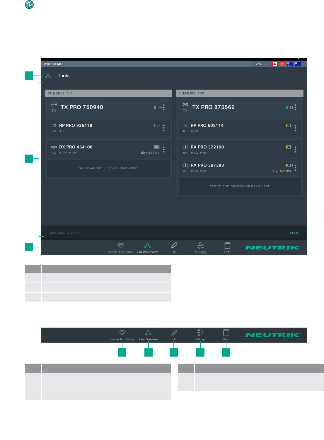
The XIRIUM PRO app enables convenient operation and control of the devices from a tablet.
4.3.1 Overview of operation elements
2
3
21 3 4 5
1
Pos. Description
1Page title
2Operation and display area
3 Navigation bar
Navigation bar
Pos. Description
1Connection setup button
2Links/Overview button
3Edit button
Pos. Description
4Settings button
5Help button
•Tapping a button opens the associated page.
•When the page is active, the pictogram is green and the text is white.
16
User Manual – XIRIUM PRO® CA | BDA 471 2017/03
Description of product
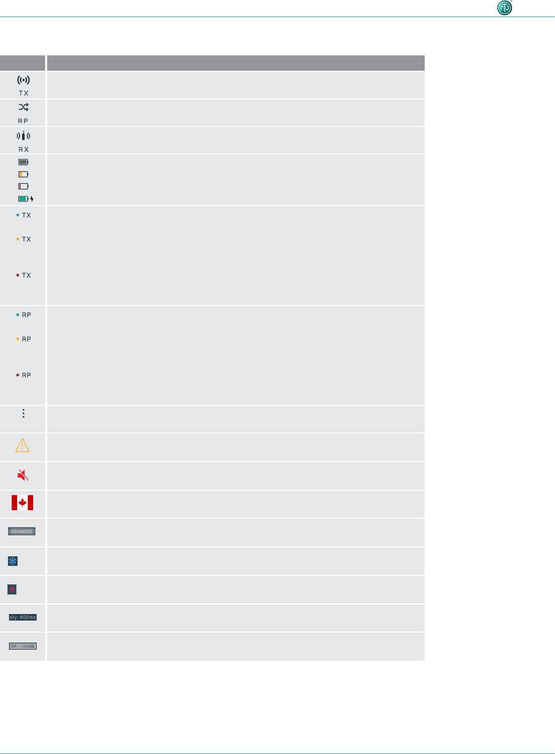
Symbols in the app
Symbol Description
The displayed device is a TX.
The displayed device is a RX with a repeater module.
The displayed device is a RX.
The battery level is between 40 % and 100 %.
The battery level is below 40 %.
The battery level is below 20 %. Connect the device to the mains supply.
Animated display: Battery is charging.
The signal quality received from the TX is good, which refers to a proper RSSI level and
a low packet loss.
The signal quality received from the TX is critical. This is either due to a critical
RSSI level or a critical packet loss.
On Edit page the signal quality bar is monitored in detail.
The signal quality received from the TX is bad. This is either due to a bad RSSI level or
a high packet loss.
On Edit page the signal quality bar is monitored in detail.
The signal quality received from the RP is good, which refers to a proper RSSI level and
a low packet loss.
The signal quality received from the RP is critical. This is either due to a critical
RSSI level or a critical packet loss.
On the Edit page the signal quality bar is monitored in detail.
The signal quality received from the RP is bad. This is either due to a bad RSSI level or
a high packet loss.
On the Edit page the signal quality bar is monitored in detail.
Display device options button
Tapping this button opens the options menu.
Indicates that a message with information is pending for this device. The information is
displayed in plain text on the Edit page of the selected device.
Mute icon: Indicates, if RX is muted
Zone indicator: Displays to which country settings the devices in use are programmed.
Advanced mode indicator: Displays, if advanced mode is switched ON.
LOW Device temperature is LOW.
HIGH Device temperature is HIGH.
Delay indicator: Indicates in the Links / Overview window if the delay on a RX is
switched on.
RF attenuation indicator: Indicates in the Links / Overview window if the RF
attenuation on a RX is switched on.
17
User Manual – XIRIUM PRO® CA | BDA 471 2017/03
Description of product
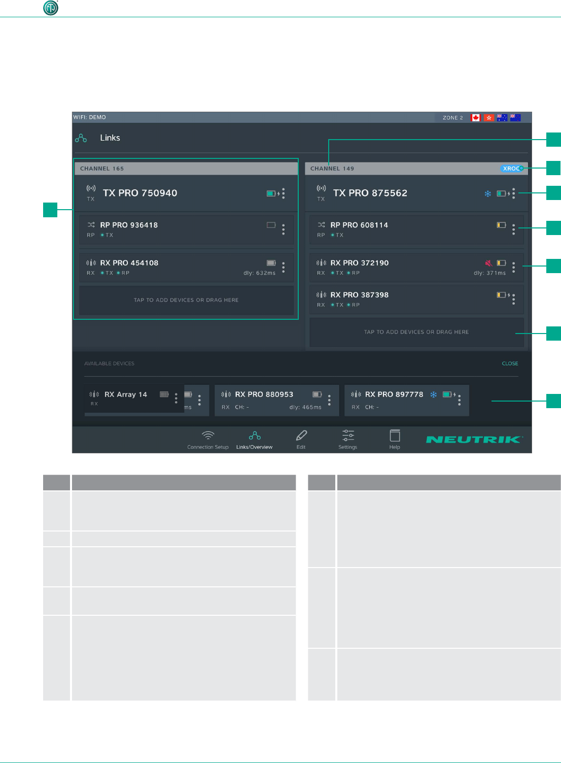
Pos. Description
1Transmission path
This grouping displays all devices that are in one
RF channel
2Transmission channel
3XROC indicator
Is displayed when XROC mode is active for the
RF channel
4TX display
1 TX is needed for each transmission path
5Repeater display
As an option, repeaters may be used.
A maximum 1 repeater per RF channel is possible.
•The display is highlighted in red when there is a
poor connection to the TX, or none at all.
Pos. Description
6RX display
Each eld represents one device.
A minimum 1 RX is needed for each transmission
path.
•The display is highlighted in red when there is a
poor connection to the TX, or none at all.
7Button for adding devices to transmission
path
•Add a device: Use drag&drop to add a device
from AVAILABLE DEVICES.
•Add several devices: Tap button and select
device from AVAILABLE DEVICES.
8AVAILABLE DEVICES
Displays all available devices which have not yet
been assigned to a transmission path.
Tapping OPEN/CLOSE opens/closes the display.
4.3.2 Links/Overview page
All devices that were added to the network via an access point are displayed on this page. The devic-
es are grouped according to transmission path. Each transmission path is assigned to one transmis-
sion channel. In stand-alone mode, the Links/Overview page is inactive.
3
2
4
5
6
7
8
1
18
User Manual – XIRIUM PRO® CA | BDA 471 2017/03
Description of product
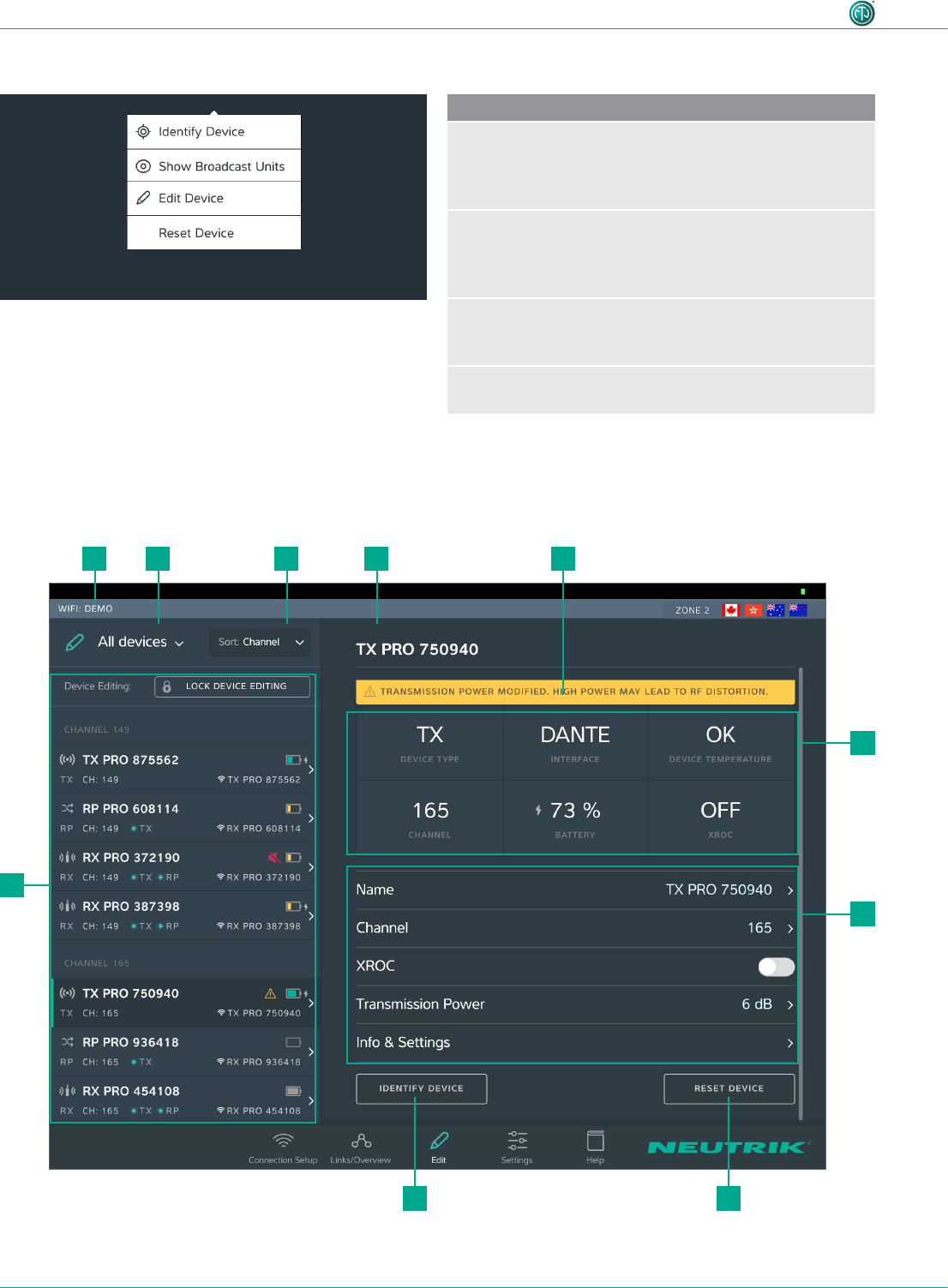
Device options menu
Description
Identify Device
Tap the button to identify a single device: The
power LED of the device slowly ashes red for about
10 seconds.
Show Broadcast Units
Tap the button: The power LEDs of all devices which are
assigned to the same channel slowly ash red for about
10 seconds.
Edit Device
Opens the Edit Device page so all properties of the
device can be edited.
Reset Device
Reset device properties to factory state
4.3.3 Edit page
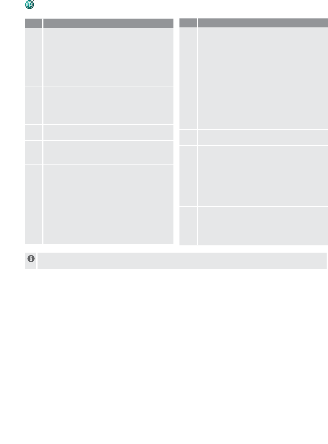
Edit TX
9
5
6
110 2 3 4
78
19
User Manual – XIRIUM PRO® CA | BDA 471 2017/03
Description of product
Pos. Description
1Filter devices drop-down menu
Only the devices that meet the lter criteria are
displayed.
•All Devices: List all devices.
•Low Battery: Only list devices on which the
battery is weak.
•Out of Range: Only list devices that receive a
poor signal, or none at all.
2Sorting drop-down menu
Species the criteria for sorting the devices.
•Channel: Devices are sorted according to
channel.
•Type: Devices are sorted according to type.
3Device Name
Displays the device name entered by the user.
4Note
Contains useful information for safe, trouble-free
operation.
5Device Properties
•Device Type: Device is a TX.
•Interface: Indicates the module being used.
•Device Temperature: Indicates the temperature
of the device (low, ok or high)
•Channel: Indicates the channel the device is
transmitting on.
•Battery: Indicates the battery charge status
in %.
•XROC: Indicates whether the XROC mode is
ON/OFF.
Pos. Description
6Adjustable properties
Tapping on a property opens the associated sub-
page.
•Name: Opens the page for changing the device
name.
•Channel: Opens the page for changing the
transmission channel.
•XROC: Tapping this button toggles the
XROC mode ON/OFF.
•Transmission Power: Opens the page for
adjusting the transmission power of the TX/
repeater.
•Info & Settings: Opens a page with information
about the device.
7Reset Device button
Resets the device to factory state.
8Identify Device button
The power LED of the device selected will slowly
ash for about 10 seconds.
9Overview of the connected devices
Lists all connected devices according the set lter
and sorting criteria.
The selected device is marked with a green bar
and a dark background.
10 Name of access point used
In standalone mode the Allow link button is shown on the Edit page. Tapping the Allow link button starts the
connection process of the TX.
20
User Manual – XIRIUM PRO® CA | BDA 471 2017/03
Description of product
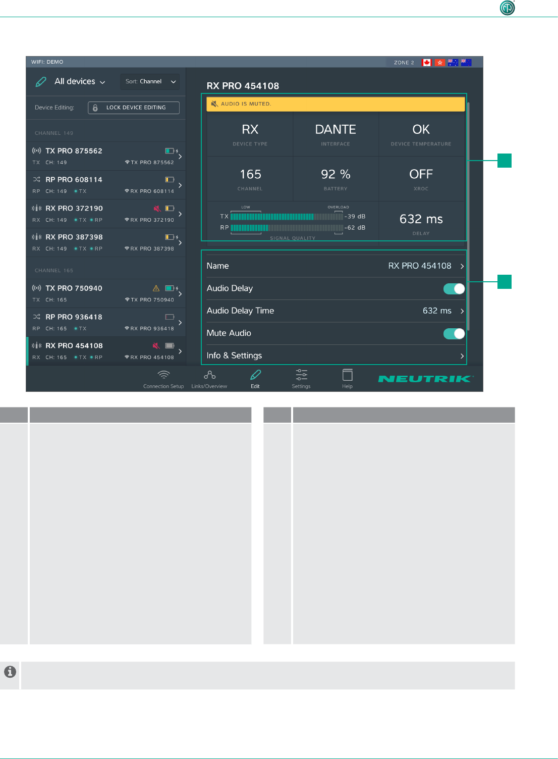
Edit RX
Pos. Description
1Device properties
•Device Type: Indicates that the device is an RX.
(for RX with repeater module: RP)
•Interface: Indicates the module being used.
•Device Temperature: Indicates the temperature
of the device (low, ok or high)
•Channel: Indicates the channel the device is
assigned to.
•Battery: Indicates the battery level in %.
•XROC: Indicates whether the transmission path
of the XROC mode is ON/OFF.
•Signal quality: Indicates the signal quality
of the signals received from the TX and/or
repeater. Signal quality is a combination of RSSI
Level and packet loss.
•Delay: Indicates the set delay time in
milliseconds, feet or meters, or indicates the
delay is off.
Pos. Description
2Settable properties
Tapping on a property opens the associated sub-
page.
•Name: Opens the page for changing the device
name.
•Audio Delay: Tap the button to activate/
deactivate the delay.
•Audio Delay Time: Opens the page for setting
the delay time.
•Mute Audio: Mutes this RX unit
•Info & Settings: Opens a page with information
about the device.
In standalone mode the Link button is shown on page Edit. Tapping the Link button links this RX to the TX.
1
2
21
User Manual – XIRIUM PRO® CA | BDA 471 2017/03
Description of product
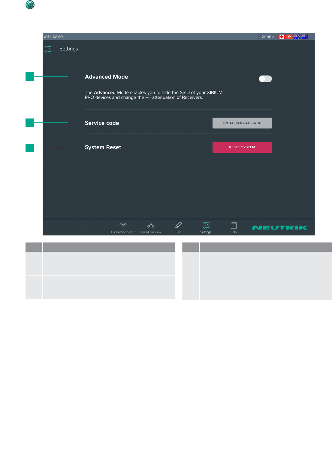
4.3.4 Settings page
Pos. Description
1Reset System button
Tapping this button opens a window with reset
options.
2Enter service code button
Opens entry eld for service code
(only for service personnel)
Pos. Description
3Reset System button
Tapping this button opens a window with reset
options.
2
3
1
22
User Manual – XIRIUM PRO® CA | BDA 471 2017/03
Description of product
2
1
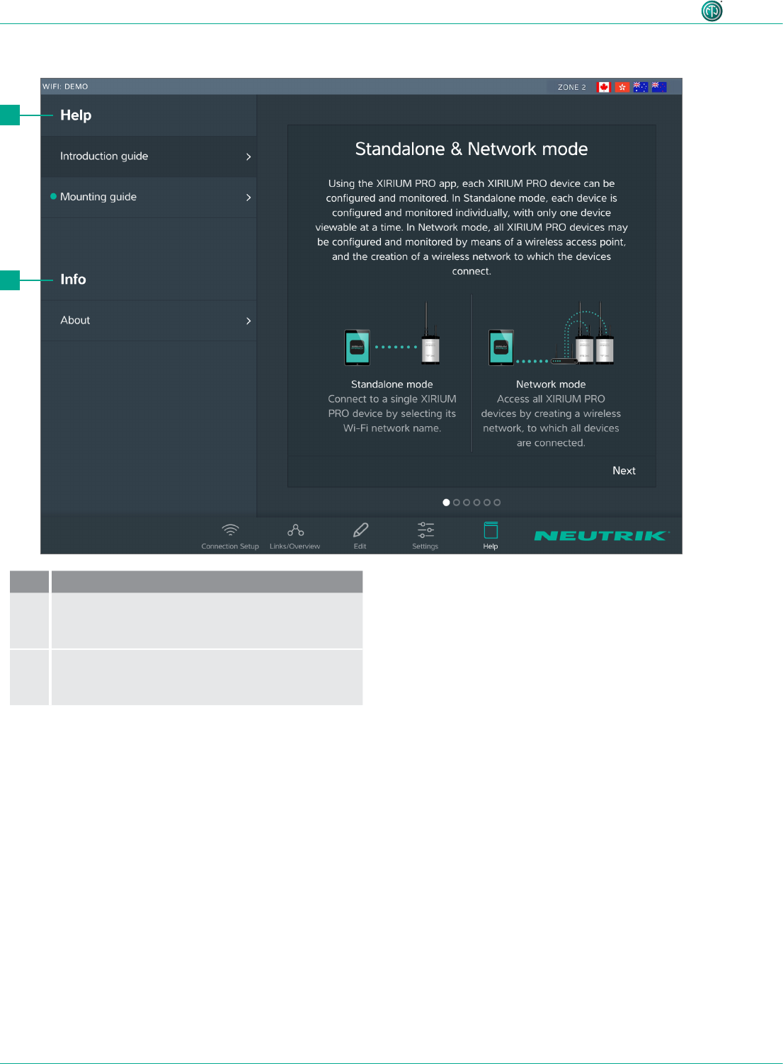
4.3.5 Help page
Pos. De scription
1Help
Useful information for a proper XIRIUM PRO
setup.
2Information about the software
Software Version: Version of the installed app.
Version Date: Date app was issued
23
User Manual – XIRIUM PRO® CA | BDA 471 2017/03
Description of product
4.4 Getting started
The XIRIUM PRO system makes it possible to replace conventional cable connections between audio
sources and audio sinks (referred to in short as "peripheral devices" below) with a robust radio con-
nection.
With just 2 devices, the transmitter (TX) and the receiver (RX), an audio signal can be transmitted
quickly and cost-efciently. The XIRIUM PRO system transfers audio signals (LINE level) as well as
digital audio signals (AES or DANTE) in studio quality with an extremely low latency time.
9 channels in the 5 GHz band are available for transmitting the audio signal. Up to two audio signals
can be transmitted in one RF channel with no loss to audio quality. The distance between transmit-
ter and receiver can be more than 3200 feet.1 The actual distance between transmitter and receiver
depends on the specic environmental conditions (line of sight, obstacles in the link, reections,
external RF signals, etc.).
Depending on the distance between transmitter and receiver, the transmission power may be manu-
ally controlled using the associated app in order to ensure the RSSI level remains in the "green range".
In order to be able to establish a connection between TX and RX, the devices must be separated by
a distance of at least 10 feet (using 6 dBi antenna and transmission power set to -3 dB).
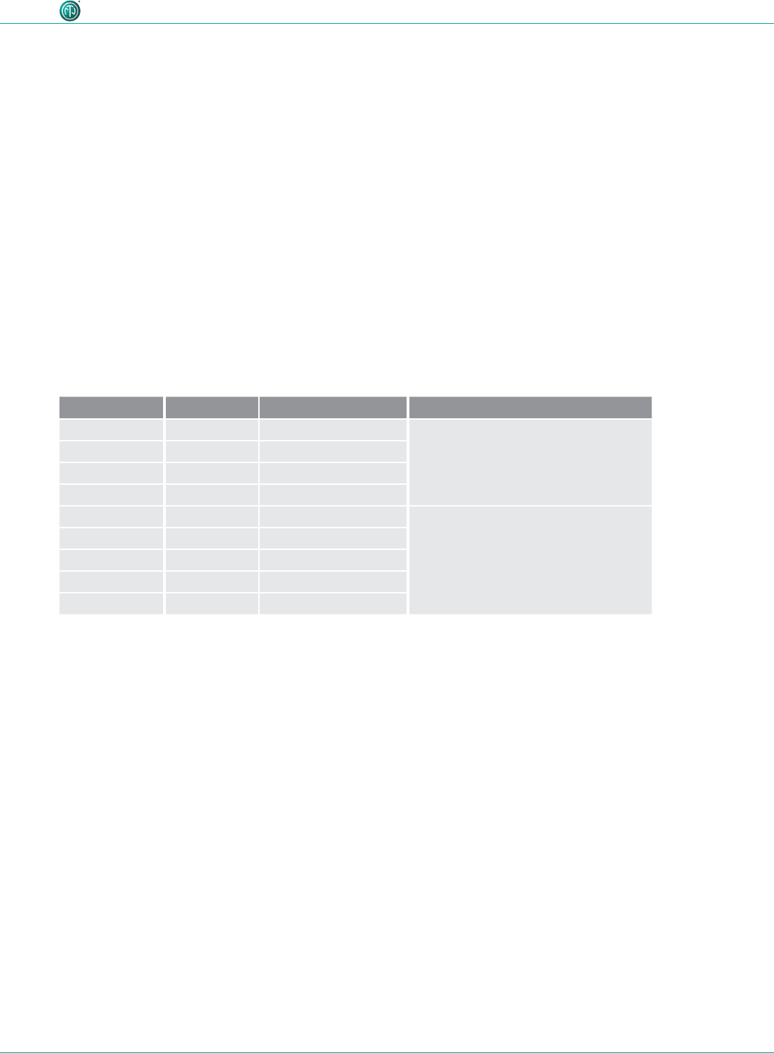
Channel Medium frequency
UNII-1 band Ch 36 5180 MHz Only allowed for indoor use with
23 dBm EIRP (200 mW)
2
Ch 40 5200 MHz
Ch 44 5220 MHz
Ch 48 5240 MHz
UNII-3 band Ch 149 5745 MHz Allowed for outdoor use with
36 dBm EIRP (4 W)
2
Ch 153 5765 MHz
Ch 157 5785 MHz
Ch 161 5805 MHz
Ch 165 5825 MHz
The XIRIUM PRO system has been designed with features to simplify use. Understanding these fea-
tures will be helpful before the system is put into operation.
1 This refers to one of the UNII-3 band channels only, since the lower channels of the UNII-1 band have a lower approved
transmission power.
2 The app takes care of the maximum EIRP setting as soon as you choose a different RF channel!
24
User Manual – XIRIUM PRO® CA | BDA 471 2017/03
Description of product
It is highly recommended to choose a 2.4 GHz channel according to prior agreement with
event management. Uncoordinated usage of the 2.4 GHz channel may lead to connectivity
issues in the 2.4 GHz transmission path due to high trafc. The audio transmission is not
affected by the 2.4 GHz transmission path!
4.4.2 Repeater
A "repeater" is an RX equipped with a repeater module. The repeater is used in the following situ-
ations:
•Stabilizing transmission paths
The repeater receives the signal from the TX and transmits a redundant signal to the RX. The
redundant signal stabilizes the connection and reduces efferts caused by interferences.
•Overcoming obstacles
If no line-of-sight connection is possible, obstacles such as walls, glass or even corners can be
overcome with the repeater.
•Extending distances
When a repeater is used, the distance between TX and RX can be doubled.
OVERLOADLOW
-80 -60 -28 -25
4.4.3 Signal quality bar
The signal quality bar displays both RSSI level and packet loss. The scale of the bar refers to the RSSI
level (Received Signal Strength Indicator). It is recommend to have an RSSI level not appearing in the
“low” and “overload” area.
The color of the bar displays the packet loss:
•Bar is displayed green: packet loss is low
•Bar is displayed orange: packet loss is critical
•Bar is displayed red: packet loss is high.
A high packet loss increases the probability of losing audio.
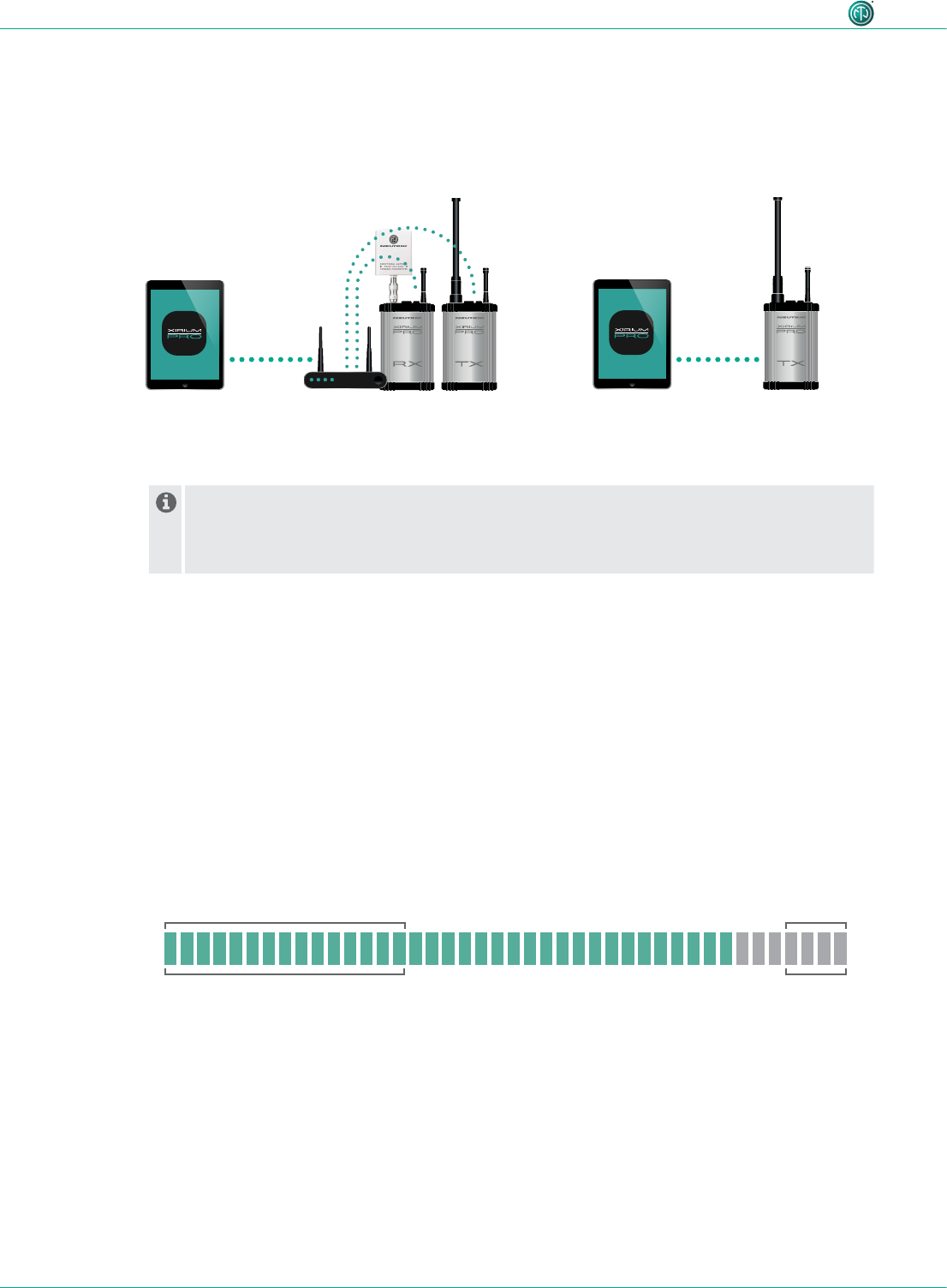
4.4.1 App
The app is the central control interface of the XIRIUM PRO system. Using the app, transmission paths
and networks can be created and managed. The app provides information about the current status
of the connected devices and transmission paths. The XIRIUM PRO devices can be connected to the
app through 2 modes:
Stand-alone mode
Only 1 device is directly connected
to the app.
Network mode
Several devices connected to the app via an
access point.
25
User Manual – XIRIUM PRO® CA | BDA 471 2017/03
Description of product
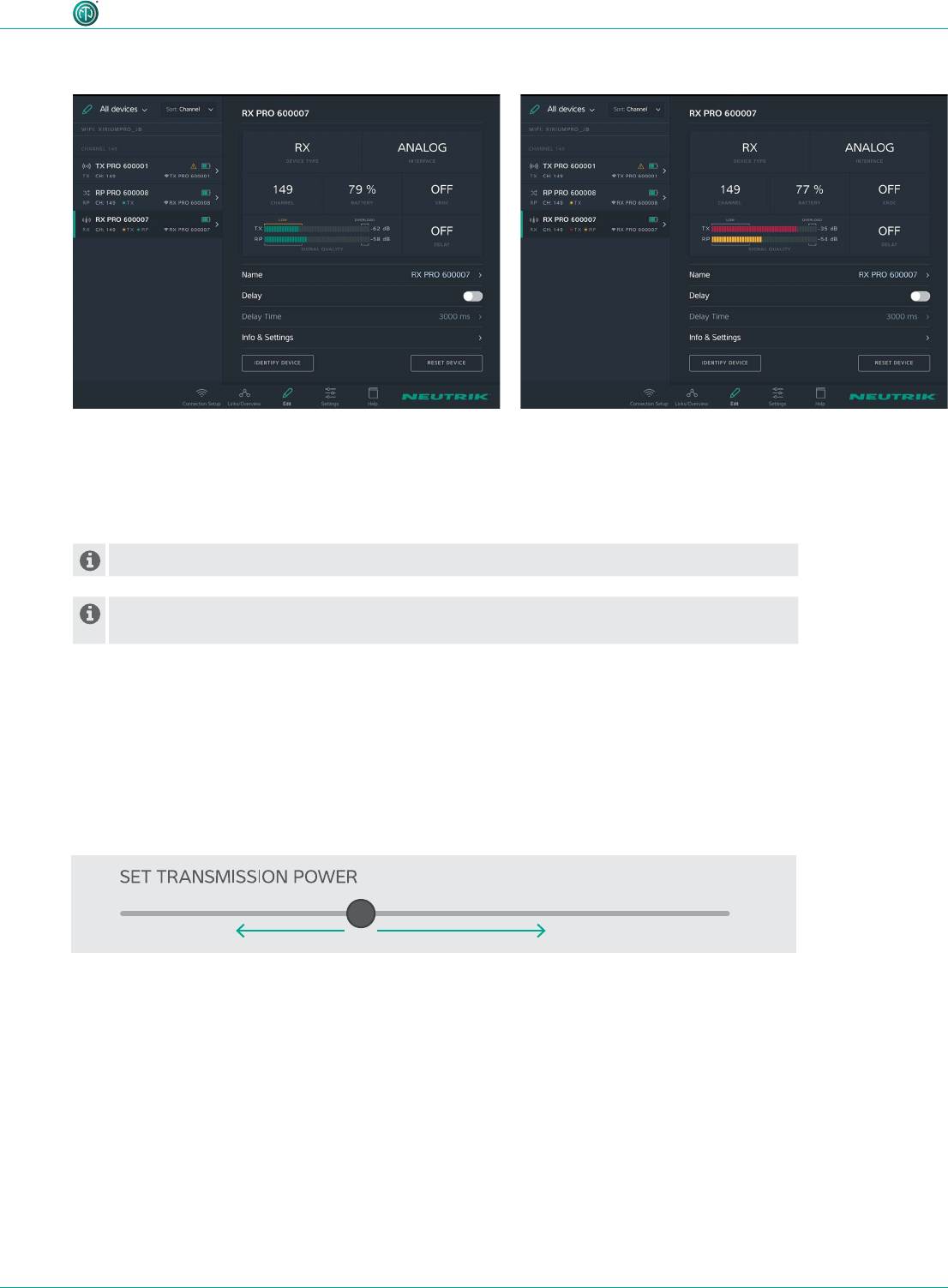
An improper RSSI level can be modied by increasing or decreasing the transmission power.
If the packet loss is high, the position of the devices have to be modied. Double-check if
there are other devices operating on the some channel and change the RF channel.
•RSSI level received from the TX is critical.
•The packet loss received from TX and RP is low.
We recommend to increase the transmission power of
the TX.
•RSSI level received from TX and RX are OK
•The color of the bars indicate a high (TX) and a critical
(Repeater) packet loss.
We recommend to relocate the devices and / or change
the RF channel.
Examples
4.4.4 Transmission power
Depending on the application, the transmission power should be adjusted with the app so the RSSI
level on the receiver remains in the recommended range. However, the 10-foot minimum distance
between the TX/RX must always be maintained. This minimum distance applies when the 6 dBi an-
tenna and a transmission power of -3 dB are used. If the 9 dBi antenna and/or a higher transmission
power are used, the minimum distance increases.
Decreasing transmission power
In indoor areas and over short
distances.
Increasing transmission power
In outdoor areas and over longer distances.
26
User Manual – XIRIUM PRO® CA | BDA 471 2017/03
Description of product
4.4.5 XROC mode
If only 1 audio signal per RF channel is needed, we recommend using XROC mode. XROC stands for
"Extreme Ruggedized One Channel“. In XROC mode, only 1 audio signal at 6 Mbit/s is available for
each RF channel. The connection between the devices is much more stable in XROC mode, because
external inuences do not interfere with the RF signal between the XIRIUM PRO devices as much.
External inuences include strong reections of the RF signal in a room or from buildings, or external
signals. The power consumption of the devices is higher in XROC mode.
The increase in the performance range is illustrated in the RX signal quality bar, which displays a
smaller “low” area when XROC mode is used.
If XROC mode is enabled on a TX, only audio channel 1 is being transmitted. Therefore a
linked RX will have no audio on channel 2.
OVERLOAD
-80 -70 -28 -25
LOW
4.4.6 Antennas
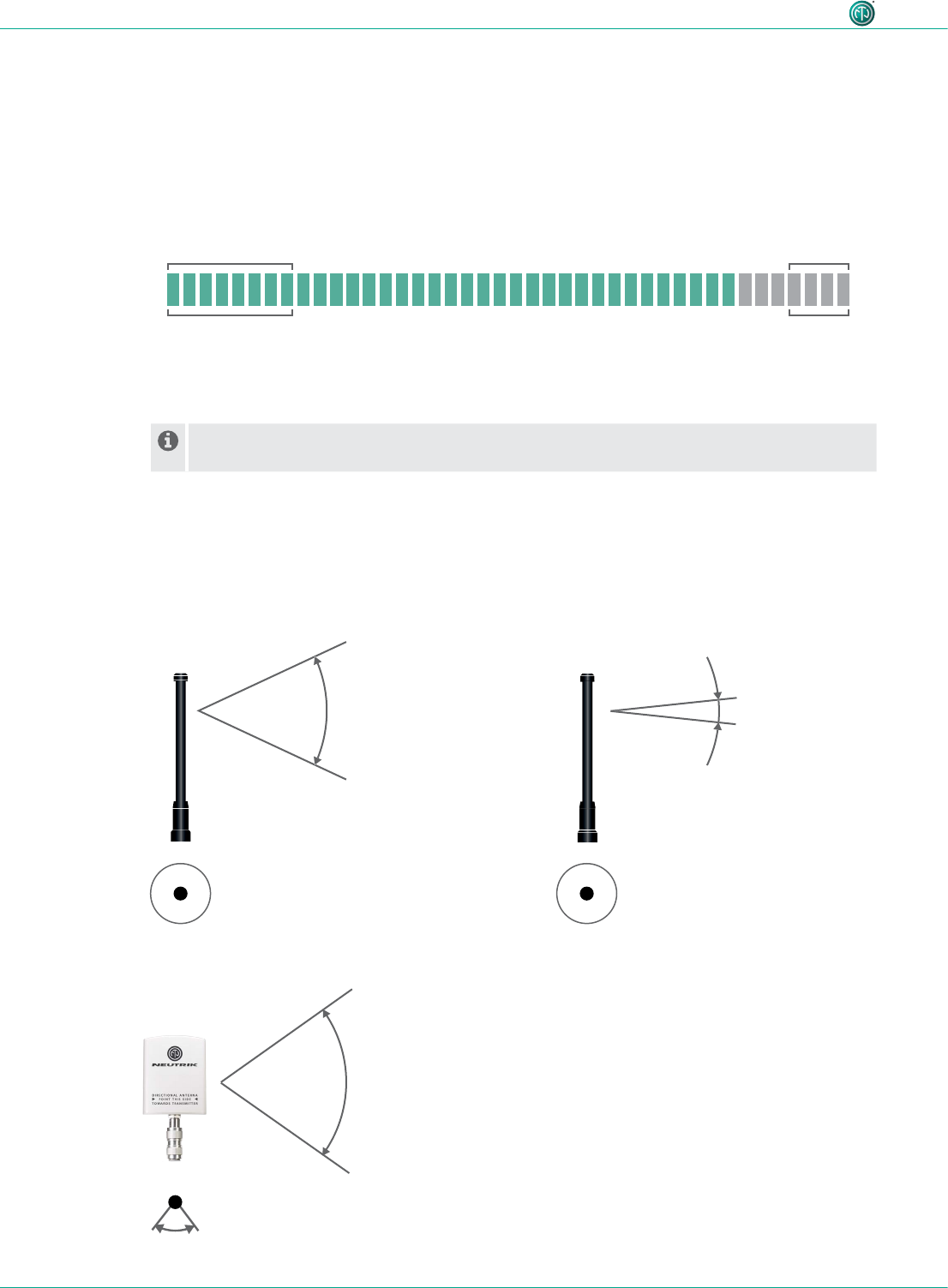
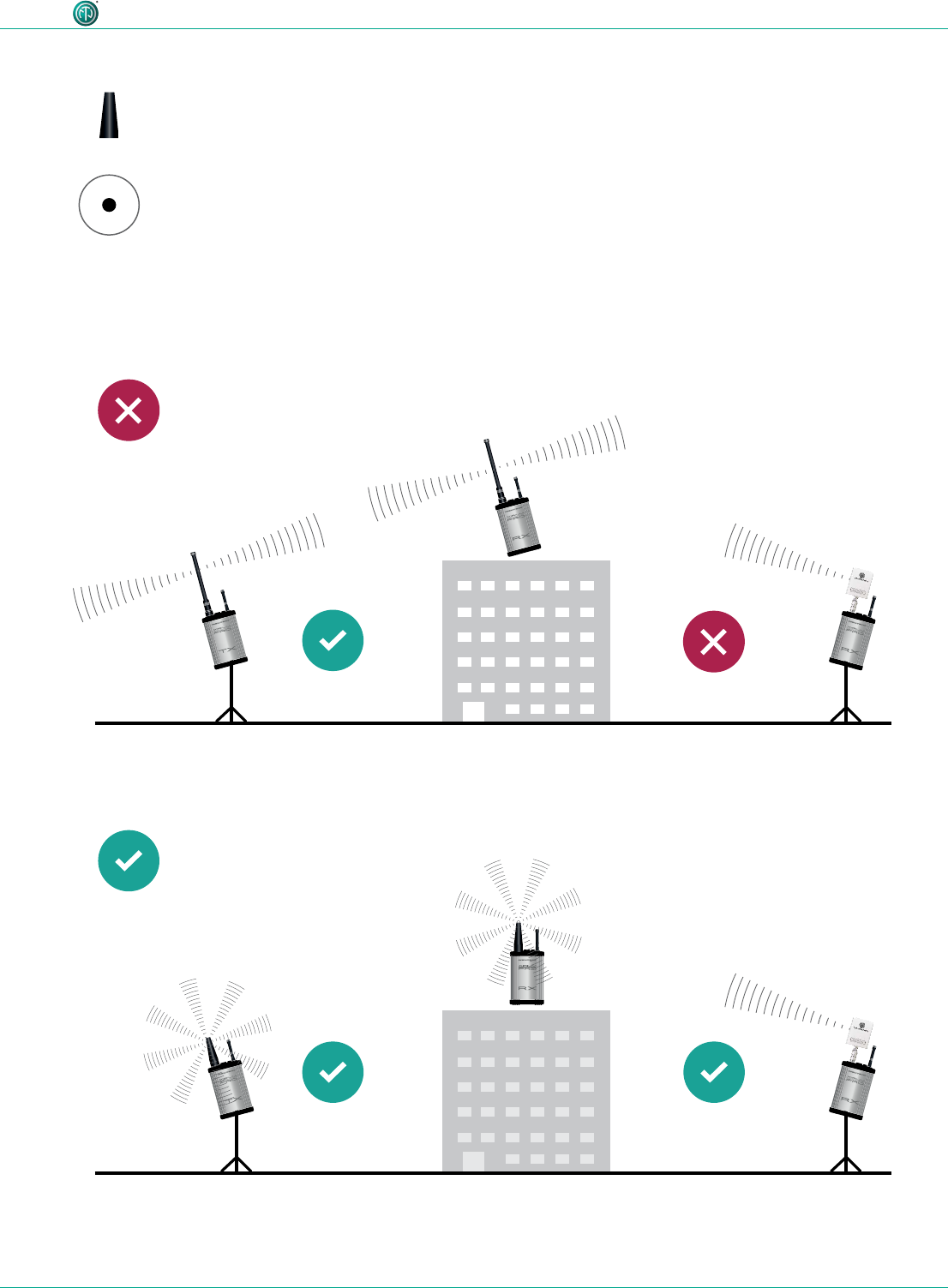
XIRIUM PRO uses omnidirectional antennas with xed vertical radiating angles. Neutrik offers two
different antennas: the standard 6 dBi antenna, featuring a 25° vertical angle, and an optional
9 dBi antenna with a 12.5° vertical angle.
6 dBi 9 dBi
25° vertical
360° horizontal 360° horizontal
12.5° vertical
14 dBi
40° horizontal
35° vertical
For pure receivers!
For pure receivers Neutrik recommends to use
a directional antenna. It helps focusing on the
TX signal and avoids disturbances from other
systems. There's an N-type adapter provided with
the antenna to mount it directly on the device.
27
User Manual – XIRIUM PRO® CA | BDA 471 2017/03
Description of product
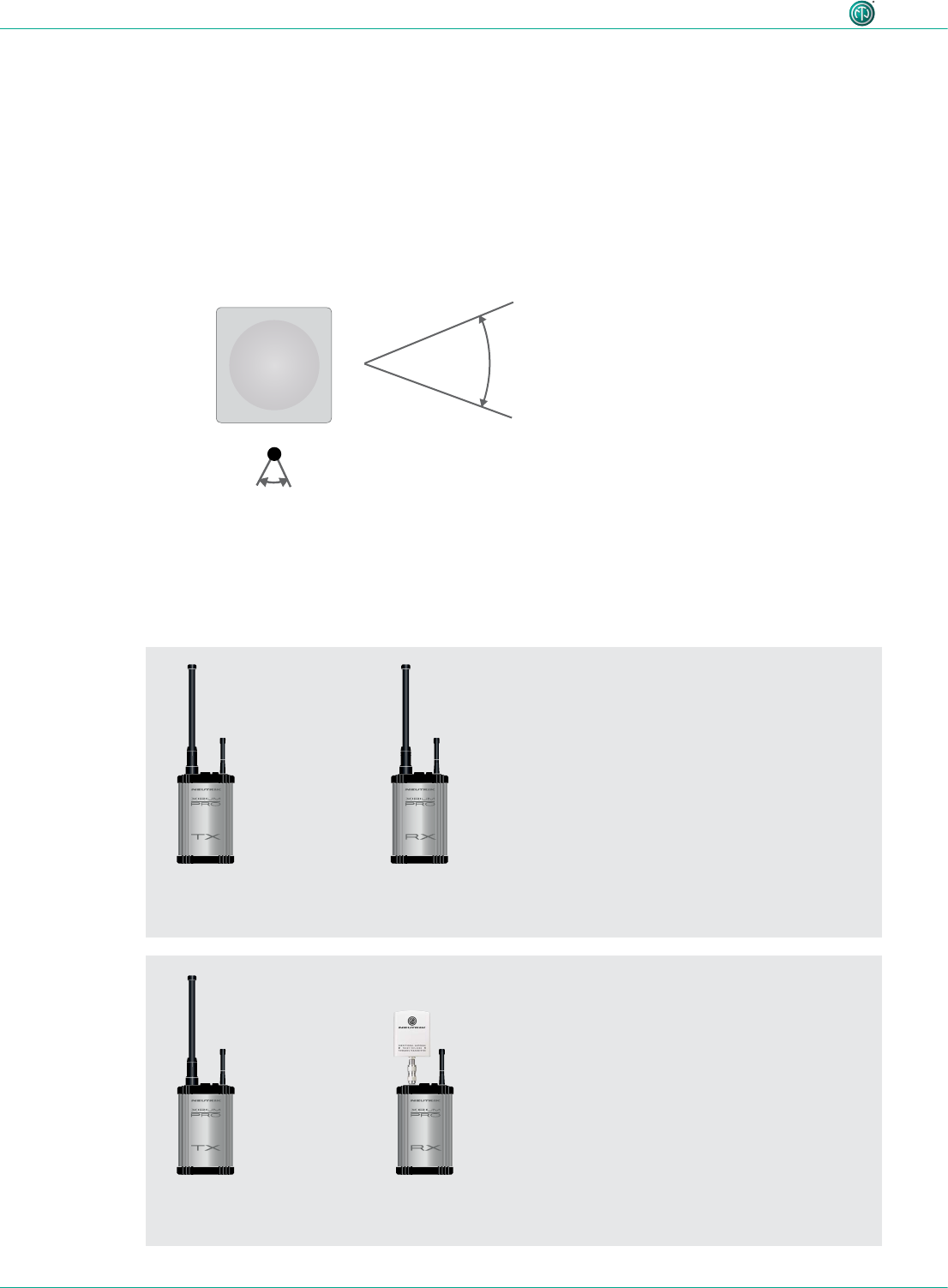
For receiver with a repeater module inserted!
2 dBi
360° horizontal
360° vertival
Not correct positioning
Correct positioning
The 2 dBi omnidirectional antenna should be used
for applications where a parallel alignment of the
TX - RX antenna on the same height can't be es-
tablished.
Due to a lower antenna gain, the transmission range
is less.
28
User Manual – XIRIUM PRO® CA | BDA 471 2017/03
Description of product
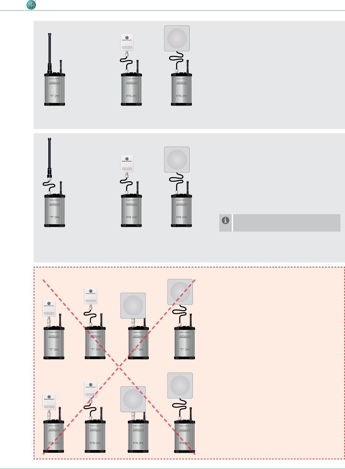
18 dBi (NXPA-18-18-18)
18° horizontal
18° vertical
For pure receivers as a remote antenna.
NXPA-6-360-25
or NXPA-9-360-12.5
NXPA-6-360-25
or NXPA-9-360-12.5
NXPA-6-360-25
or NXPA-9-360-12.5
NXPA-14-40-35
4.4.7 Remote antennas
If the 5 GHz antenna and the 2,4 GHz antenna need to be aligned differently in terms of angle, it’s
advisable to remote the 5 GHz link. For that purpose Neutrik offers an antenna cable (NKXPA-5) with a
length of 5 meters and an attenuation of 4 dB. There is also an additional directional antenna available
for such applications having a gain of 18 dBi. This antenna must be used only for pure receivers and
not for any transmitting device, hence also not for a repeater. Like all other XIRIUM PRO antennas this
antenna has a vertical polarization. It is necessary to gear this antenna in the correct angle towards
the TX antenna. A correspondent graphical indication can be found on the backside of the antenna.
4.4.8 Antenna combinations
These are possible antenna combinations for the XIRIUM PRO system:
•common setup
•point-to-multipoint
•setup with directional antenna on RX
•point-to-multipoint
•Focusing on the TX signal and avoid
disturbances from other systems
29
User Manual – XIRIUM PRO® CA | BDA 471 2017/03
Description of product
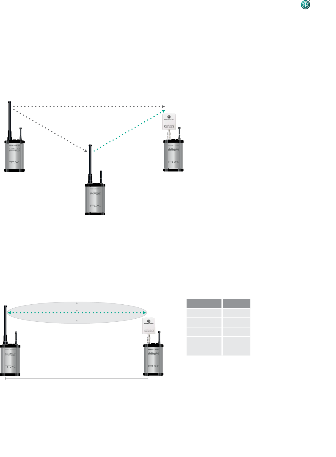
NXPA-6-360-25
or NXPA-9-360-12.5
NKXPA-5
NXPA-N-FF
NXPA-6-360-25
or NXPA-9-360-12.5
Transmitter
Repeater
NKXPA-5
NXPA-14-40-35
NKXPA-5
NXPA-14-40-35
NKXPA-5
NXPA-18-18-18
NKXPA-5
NXPA-18-18-18
or
or
•remote setup on RX
•point-to-multipoint
•different alignment of 2,4 GHz- and 5 GHz
antenna required
•remote setup on TX + RX
•point-to-multipoint
•Option to mount the antennas outdoor
and keep the devices indoor due to
temperature reasons (< 0°C / > 50°C)
•Shorter range than with the other setups
For a remote setup of the TX antenna
an adapter (NXPA-N-FF) is required.
Note!
Due to RF regulations it’s not allowed
to use the directional antennas on a
transmitter or repeater!
30
User Manual – XIRIUM PRO® CA | BDA 471 2017/03
Description of product
4.4.9 Line-of-sight and redundant RF path
For a reliable wireless audio link, make sure all XIRIUM PRO devices have a line-of-sight connection.
If a line-of-sight connection cannot be established, the receiver may be in a drop-out zone. A drop-
out zone is a point where phase cancellation occurs between the direct signal and the deected one.
Relocating the transmitter (TX) and/or receiver (RX) can help eliminate this phase anomaly. Using a
repeater can also eliminate the problem of the drop out zone. A repeater effectively provides a re-
dundant RF path to all receivers within range. The RX receives identical audio signals from both the
transmitter and repeater.
distance d radius r
150 ft 2.7 ft
300 ft 3.8 ft
900 ft 6.6 ft
1500 ft 8.5 ft
3000 ft 12 ft
4.4.10 Antenna height + distance
Consider the Fresnel zone, which is an ellipsoidal area between wireless devices. For XIRIUM PRO
TX and RX devices, there should be no obstacles within the Fresnel zone. Maintaining proper
antenna height is essential to ensure trouble-free communication between XIRIUM PRO devices. To
dene an area that is free of obstacles, use the following chart to estimate proper antenna height.
Transmitter signal Identical audio signal
from two different
sources = redundancy
Repeater
signal
RX with repeater module
distance d
radius r
Fresnel zone

31
User Manual – XIRIUM PRO® CA | BDA 471 2017/03
Description of product
4.5 Selecting transmission channels
4.5.1 Automatic selection of transmission channels
A TX is assigned to channel 149 by default. If channel 149 is already occupied by a different TX, the
device searches for the next free channel. The TX saves the last channel used. When switched on
again, the TX uses the last channel used, as long as it is not occupied. If the TX changes the channel,
all devices in the transmission path are assigned to the new channel.
4.5.2 Manual selection of transmission channels
The transmission channel can also be manually adjusted with the app. To guarantee a trouble-free
process, the app prevents an adjacent channel from being selected. The transmission channel can
be changed on the Edit page. More information in Section "Changing the transmission channel"
on page 40.