Neutrik XPT Digital Wireless Audio Transmitting Unit (TX) User Manual part 1
Neutrik AG Digital Wireless Audio Transmitting Unit (TX) part 1
Neutrik >
Contents
- 1. User manual
- 2. User Manual part 1
- 3. User Manual part 2
- 4. User Manual
User Manual part 1
User Manual
Applies to XIRIUM PRO CANADA, AUSTRALIA, and
NEW ZEALAND devices

2User Manual – XIRIUM PRO® CA | BDA 471 2017/03
Imprint
Subject to change due to technical advances! This user manual corresponds to the level of
technology at the time the product was delivered and not the current stage of development at
Neutrik.
If any pages or sections of this user manual are missing, please contact the manufacturer at the
address listed below.
Copyright
This user manual is protected by copyright. The user manual must not be duplicated, reproduced,
microlmed or translated, or converted to be saved and processed in EDP systems, neither as
excerpts nor in full, without the express written authorization of Neutrik.
Copyright by: © Neutrik® AG
Document identification
Document No: BDA 470
Version: 2017/03
cThis user manual applies to firmware 3.0 and app version 3.0!
Language: English
Original language: German
Each user manual in a different language is a translation of the operating manual in German.
Manufacturer
Neutrik® AG
Im alten Riet 143
9494 Schaan
Liechtenstein
T: +423 2372424
F: +423 2325393
E: neutrik@neutrik.com
www.neutrik.com

3User Manual – XIRIUM PRO® CA | BDA 471 2017/03
Table of contents
1 About this document ..............................................4
1.1 Signicance of the user manual .............................4
1.2 Designation ..........................................................4
1.3 Explanation of symbols .........................................5
1.3.1 Symbols in illustrations ....................................5
1.4 Target group .........................................................5
2 Safety ........................................................................6
2.1 Warning information and signal words ..................6
2.2 Warning symbols ..................................................6
2.3 Important regulatory notes ...................................7
2.3.1 Radio frequency radiation exposure informa-
tion .........................................................................8
2.4 Important safety instructions .................................8
2.5 Proper use ..........................................................10
2.6 Foreseeable improper use ...................................10
3 Components and accessories ................................ 11
3.1 XIRIUM PRO components .................................... 11
4 Description of product ..........................................13
4.1 XIRIUM PRO base station ..................................... 13
4.2 Modules ............................................................. 14
4.2.1 TX modules ...................................................14
4.2.2 RX modules ..................................................14
4.3 XIRIUM PRO app ................................................. 15
4.3.1 Overview of operation elements .................... 15
4.3.2 Links/Overview page .....................................17
4.3.3 Edit page ...................................................... 18
4.3.4 Settings page ................................................21
4.3.5 Help page ..................................................... 22
4.4 Getting started ...................................................23
4.4.1 App ..............................................................24
4.4.2 Repeater ....................................................... 24
4.4.3 Signal quality bar ..........................................24
4.4.4 Transmission power ......................................25
4.4.5 XROC mode .................................................26
4.4.6 Antennas ...................................................... 26
4.4.7 Line-of-sight and redundant RF path .............28
4.4.8 Antenna height + distance ............................28
4.4.9 Line-of-sight and redundant RF path .............30
4.5 Selecting transmission channels ..........................31
4.5.1 Automatic selection of transmission channels ...31
4.5.2 Manual selection of transmission channels ....31
5 Operation ...............................................................32
5.1 Setting devices into operation .............................32
5.2 Setting up the transmission path ......................... 33
5.3 Installing and starting the app .............................34
5.4 Connecting devices with the app ........................34
5.4.1 Connecting devices in stand-alone mode ......34
5.4.2 Connecting devices in network mode ...........35
5.5 Arranging the radio transmission path .................38
5.6 Conguring the device parameters ......................39
5.7 Editing system settings ........................................ 43
5.7.1 System reset ..................................................43
5.7.2 Advanced Mode ...........................................43
5.8 Setting up and mounting the XIRIUM PRO system ..44
5.8.1 Positioning the devices ..................................44
5.8.2 Positioning the repeater ................................ 45
5.8.3 Systems with several transmitters ..................45
5.8.4 Fastening and securing XIRIUM PRO devices ... 46
5.9 Upgrading rmware ............................................47
5.9.1 Installing the XIRIUM PRO Firmware Upgrade
Manager ................................................................47
5.9.2 Executing a rmware upgrading ................... 48
5.9.3 Uninstalling the XIRIUM PRO Firmware Upgrade
Manager ................................................................ 50
6 Troubleshooting.....................................................51
7 After operation ......................................................52
7.1 Dismounting devices ............................................ 52
7.2 Transporting ........................................................52
7.3 Storage ...............................................................52
7.4 Cleaning and care ...............................................52
7.5 Maintenance and repair .......................................52
7.6 Dispos al ..............................................................53
8 Appendix ................................................................54
8.1 Integrating DANTE ..............................................54
8.1.1 Introduction to DANTETM ...............................54
8.1.2 Enabling a DANTETM link ................................ 54
8.2 Access point settings ..........................................55
8.2.1 Recommended settings ................................. 55
8.2.2 XIRIUM PRO basic kit with access point .........55
8.3 Technical specications .......................................56
4User Manual – XIRIUM PRO® CA | BDA 471 2017/03
About this document
1 About this document
This user manual provides an overview of the necessary operation steps and settings of the product.
1.1 Significance of the user manual
This user manual is an integral component of the product and part of the product's safety
concept.
cMake sure that all persons who work with the product have fully read and also
understood this user manual.
cObserve all instructions exactly, especially the safety instructions.
This user manual contains important information for operating and maintaining the product
and troubleshooting minor problems safely and properly on your own.
cKeep this user manual in the immediate vicinity of the product so personnel have access
to it at all times.
cPass this user manual on to every user, e.g., by lending it, or to the future owner of the product.
cIf this user manual is lost or damaged, a copy of the operating manual
can be downloaded from the Neutrik's home page (www.neutrik.com).
1.2 Designation
Designation Explanation
XIRIUM PRO System All components:
XIRIUM PRO base stations, XIRIUM PRO modules, cables, plugs, antennas
XIRIUM PRO base
station
XIRIUM PRO TX (transmitter) without module, short TX
XIRIUM PRO RX (receiver) without module, short RX
XIRIUM PRO module Exchangeable module for the XIRIUM PRO base station
XIRIUM PRO device XIRIUM PRO base station with module plugged-in
XROC mode Extreme Ruggedized One Channel mode for a secure connection in
extreme situations.
Peripheral devices All devices which can be connected with each other via the XIRIUM PRO
devices: audio sources (transmitters) and audio sinks (receivers)
Audio source All devices which emit a signal
Audio sink All devices which receive the audio signals, e.g., loudspeakers, audio
systems (ampliers, mixing consoles, etc.)
Transmission path Wireless connection between the XIRIUM PRO devices.
A transmission path consists of 1 TX, 1 repeater (optional) and at least
1 RX.
Network All devices used which are connected to the app via an access point.
5User Manual – XIRIUM PRO® CA | BDA 471 2017/03
About this document
1.3 Explanation of symbols
In order to make this user manual easier to understand, uniform safety instructions, symbols, terms
and abbreviations were used. The following symbols designate instructions which are not relevant to
safety, yet make it easier to understand the operating manual.
^The preconditions for an action are depicted with this symbol. Complete the specied items
before carrying out the action steps which follow.
cAction steps are designated by this symbol. Carry out the action steps in the order they are
presented.
(The result of the action or the reaction of the product to the action are depicted with this
symbol.
•Lists without a mandatory sequence are presented as a list with this bullet.
1. Numbered listings are displayed in this manner.
(1) Refers to a position in an illustration.
Texts in this color designate elements on the app surface.
Wherever you see this symbol, you will nd useful information for safe, trouble-free operation
of the product.
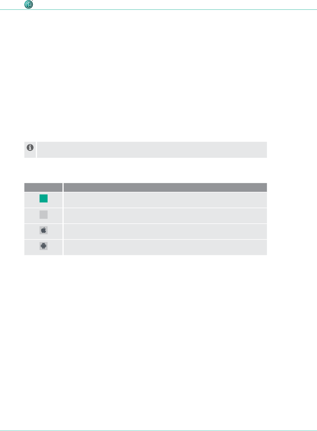
1.3.1 Symbols in illustrations
Symbol Explanation
Image position
Action steps numbered in an illustration.
Carry out the action steps in the order they are presented.
Only carry out these tasks when using an Apple iPad.
Only carry out these tasks when using an Android tablet.
1.4 Target group
This user manual is directed to sound engineers and professional personnel who have detailed expe-
rience in the sound and event technology.
Personnel who are in training must only work with this device under the supervision of experienced
persons.
1
1
6User Manual – XIRIUM PRO® CA | BDA 471 2017/03
Safety
2 Safety
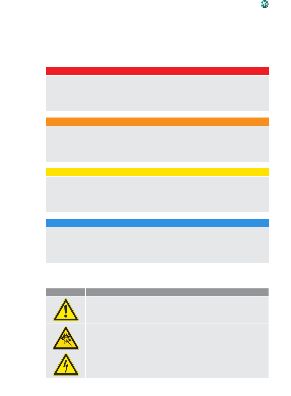
2.1 Warning information and signal words
Special warning information regarding potential dangers inherent in a particular action are presented
before instructions for an action. The warnings are ranked as follows:
DANGER
Immediate threat of danger!
This type of warning points out a situation which would result in death or severe injuries.
cIf this warning is not heeded, the threat of death or serious injuries is imminent.
WARNING
Possible threat of danger!
This type of warning points out a situation which could result in death or severe injuries.
cIf this warning is not heeded, the threat of death or serious injuries might be imminent.
CAUTION
Possible threat of danger!
This type of warning points out a situation which could result in minor or moderate injuries.
cIf this warning is not heeded, minor injuries may result.
NOTICE
Possible threat of property damage!
This type of warning points out a situation which could result in damage to the device and its
components.
cIf this warning is not heeded, property damage may result.
2.2 Warning symbols
Symbol Warning
General warning
Warning of hearing impairment
Danger of electric shock

7User Manual – XIRIUM PRO® CA | BDA 471 2017/03
Safety
2.3 Important regulatory notes
This equipment has been tested and found to comply with the limits for a Class B digital device, pur-
suant to Part 15 of the FCC Rules. These limits are designed to provide reasonable protection against
harmful interference in a residential installation. This equipment generates, uses and can radiate
radio frequency energy and, if not installed and used in accordance with the instructions, may cause
harmful interference to radio communications. However, there is no guarantee that interference will
not occur in a particular installation. If this equipment does cause harmful interference to radio or
television reception, which can be determined by turning the equipment off and on, the user is en-
couraged to try to correct the interference by one or more of the following measures:
•Reorient or relocate the receiving antenna.
•Increase the separation between the equipment and receiver.
•Connect the equipment into an outlet on a circuit different from that to which the receiver is
connected.
•Consult the dealer or an experienced radio/TV technician for help.
NOTICE
This device complies with Part 15 of the FCC Rules and with Industry Canada licence-exempt RSS
standards.
Operation is subject to the following two conditions:
1. this device may not cause harmful interference, and
2. this device must accept any interference received, including interference that may cause
undesired operation.
REMARQUE
Le présent appareil est conforme aux CNR d'Industrie Canada applicables aux appareils radio
exempts de licence. L'exploitation est autorisée aux deux conditions suivantes:
Operation is subject to the following two conditions:
1. l'appareil ne doit pas produire de brouillage, et
2. l'utilisateur de l'appareil doit accepter tout brouillage radioélectrique subi, même si le
brouillage est susceptible d'en compromettre le fonctionnement.
NOTICE
Changes or modications made to this equipment not expressly approved by Neutrik may void
the FCC and IC authorization to operate this equipment.
NOTICE
This device must be professionally installed.
NOTICE
This radio transmitter (IC: 11536A-XPT / IC: 11536A-XPR) has been approved by Industry Canada
to operate with the antenna types listed below with the maximum permissible gain indicated.
Antenna types not included in this list, having a gain greater than the maximum gain indicated
for that type, are strictly prohibited for use with this device.
Provided antennas:
• NXPA-2-360 (SOA-2456/360/1/0/V; 2 dBi gain)
• NXPA-6-360-25 (ECO6-5500-BLK-RN; 6 dBi gain)
• NXPA-9-360-12.5 (ECO9-5500-BLK-RN; 9 dBi gain)
8User Manual – XIRIUM PRO® CA | BDA 471 2017/03
Safety
2.3.1 Radio frequency radiation exposure information
This equipment complies with FCC radiation exposure limits set forth for an uncontrolled environ-
ment. This equipment should be installed and operated with minimum distance of 0,65 ft (20 cm)
between the radiator and your body.
This transmitter must not be co-located or operating in conjunction with any other antenna or trans-
mitter.
2.4 Important safety instructions
WARNING
Risk of fire or electric shock!
cTo reduce the risk of re or electric shock, do not expose this device to rain or moisture and do
not set any objects containing liquids on this apparatus.
WARNING
Danger of fire and explosion due to overheated battery!
cDo not expose batteries or battery pack to excessive heat such as re or other heat sources.
•To completely disconnect this apparatus from AC mains, disconnect the power supply cord plug
from the AC socket.
•Keep the mains plug of the power supply cord readily accessible.
Avoid property damage to the XIRIUM PRO devices due to unsuitable operating and environmental
conditions:
•Never immerse in water.
•Protect from strong sunlight.
•Never install the device near heat sources such as radiators, heating units, ovens or stoves.
•Never cover the device, to avoid overheating.
•Protect the device from impact and above all, from falling from poles, stages, tables or furniture.
•Always set up and fasten the device as shown in Section "5.8.4 Fastening and securing XIRIUM
PRO devices" on page 46.
Repair
DANGER
Danger of injury or electric shock and property damage due to improper repair!
The XIRIUM PRO devices do not contain any parts which you can repair yourself. Opening or re-
pairing the devices on your own can lead to severe damage to the devices and electrical shock or
injuries to the operator.
cDo not open the housing of XIRIUM PRO devices under any circumstances.
cDo not exchange any parts yourself.
cOnly have XIRIUM PRO devices repaired by a authorized specialist dealer.

9User Manual – XIRIUM PRO® CA | BDA 471 2017/03
Safety
Electrical connection
DANGER
Danger of electric shock when connecting to or disconnecting from a power grid!
cOnly connect the devices to mains sockets installed by authorized electricians.
cDo not handle the devices with moist or wet hands under any circumstances.
cMake sure the specied mains voltage and mains frequency agree with the values of the
power grid.
cOnly use the delivered power supply cable for connecting to the socket.
cDuring storms or whenever there is a danger of power uctuations, switch off the device and
separate from the power grid.
cEnsure that the power supply cable is not kinked, hung over sharp edges or allowed to contact
hot surfaces during operation.
cDo not use the devices if there is interference or damage to the devices, displays or
accessories.
Information for operation
cEnsure that the ambient conditions specied for XIRIUM PRO are observed during operation.
cDo not use the XIRIUM PRO devices if they are not functioning properly, have fallen or been
damaged, have become wet or if parts of the devices have been immersed in water.
cIf disruptions occur during operation:
Immediately switch off the XIRIUM PRO devices and disconnect them from the power grid.
cDo not operate the XIRIUM PRO devices in environments where ammable or explosive
materials, gases or vapors are present or could occur.
AVERTISSEMENT
Risque d'électrocution!
cPour réduire les risques d'incendie ou d'électrocution, ne pas exposer l'appareil à la pluie ni à
l'humidité et ne pas déposer d'objet contenant du liquide sur cet appareil.
AVERTISSEMENT
Risque d'incendie et d'explosion en cas de surchauffe de la pile!
cLes batteries ou bloc de batteries ne doivent pas être exposées à une chaleur excessive telle
que celle du soleil, feu ou autre source de chaleur similaire.
•Pour déconnecter complètement l’appareil du réseau d’alimentation, déconnecter le cordon
d’alimentation de la prise murale.
•La prise du réseau d’alimentation doit demeurer aisément accessible.
Pour éviter les dommages matériels aux appareils XIRIUM PRO causés par des conditions climatiques
ou de fonctionnement inadéquates :
•Ne jamais l'immerger dans l'eau.
•Protéger l'appareil des forts rayons du soleil.
•Ne jamais installer l'appareil près de sources de chaleur comme un radiateur, un appareil de
chauffage, un four ou un poêle.
•Afin d'éviter une surchauffe, ne jamais couvrir l'appareil.
•Il faut protéger l'appareil des impacts et surtout l'empêcher de tomber d'une perche, d'une
estrade, d'une table ou d'un meuble.
•Toujours installer et fixer l'appareil comme illustré dans la section «5.8.4 Fastening and securing
XIRIUM PRO devices» on page 42.

10 User Manual – XIRIUM PRO® CA | BDA 471 2017/03
Safety
Réparation
DANGER
Risque de blessures, d'électrocution et de dommages matériels en cas de réparations
inappropriées!
Les appareils XIRIUM PRO ne contiennent aucune pièce pouvant être réparée par l'utilisateur. L'ou-
verture ou la réparation des appareils par l'utilisateur peuvent entraîner des dommages graves aux
appareils, des blessures ou une électrocution de l'opérateur.
cNe pas ouvrir le boîtier des appareils XIRIUM PRO en aucun cas.
cL'utilisateur ne doit pas changer de pièces lui-même.
cFaire réparer tout appareil XIRIUM PRO uniquement par un détaillant spécialisé autorisé.
Branchement électrique
DANGER
Risque d'électrocution lors du branchement ou du débranchement au réseau électrique!
cBrancher seulement l'appareil à des prises de courant installées par des électriciens qualifiés.
cNe pas manipuler les appareils avec les mains humides ou mouillées en aucun cas.
cS'assurer que la fréquence et la tension du réseau correspondent aux spécifications.
cUtiliser seulement le cordon d'alimentation électrique fourni pour brancher l'appareil à la prise
de courant.
cPendant les tempêtes où lorsqu'il y a des risques de fluctuation de tension, fermer l'appareil et
le débrancher du réseau électrique.
cS'assurer que le cordon d'alimentation n'est pas plié, suspendu sur une arête tranchante ou en
contact avec des surfaces chaudes pendant le fonctionnement.
cNe pas utiliser les appareils s'il y a des interférences ou si l'appareil, l'écran ou les accessoires
sont endommagés.
Informations relatives au fonctionnement
cS'assurer que les conditions ambiantes prévues sont respectées pendant le fonctionnement du
XIRIUM PRO.
cNe pas utiliser les appareils XIRIUM PRO s'ils ne fonctionnent pas adéquatement, s'ils sont
tombés ou s'ils sont endommagés ou si des pièces de l'appareil ont été immergées dans l'eau.
cSi des perturbations se produisent pendant le fonctionnement :
Éteindre immédiatement l'appareil XIRIUM PRO et le débrancher du réseau électrique.
cNe faites pas fonctionner l'appareil XIRIUM PRO dans des environnements où des matériaux, des
gaz ou des vapeurs inflammables ou explosifs peuvent être présents ou peuvent se produire.
2.5 Proper use
The XIRIUM PRO devices are intended for signal transmission between an audio source and an audio
sink in accordance with the technical specications.
2.6 Foreseeable improper use
The XIRIUM PRO devices are not suitable for use in potentially explosive atmospheres.
11User Manual – XIRIUM PRO® CA | BDA 471 2017/03
Components and accessories
3 Components and accessories
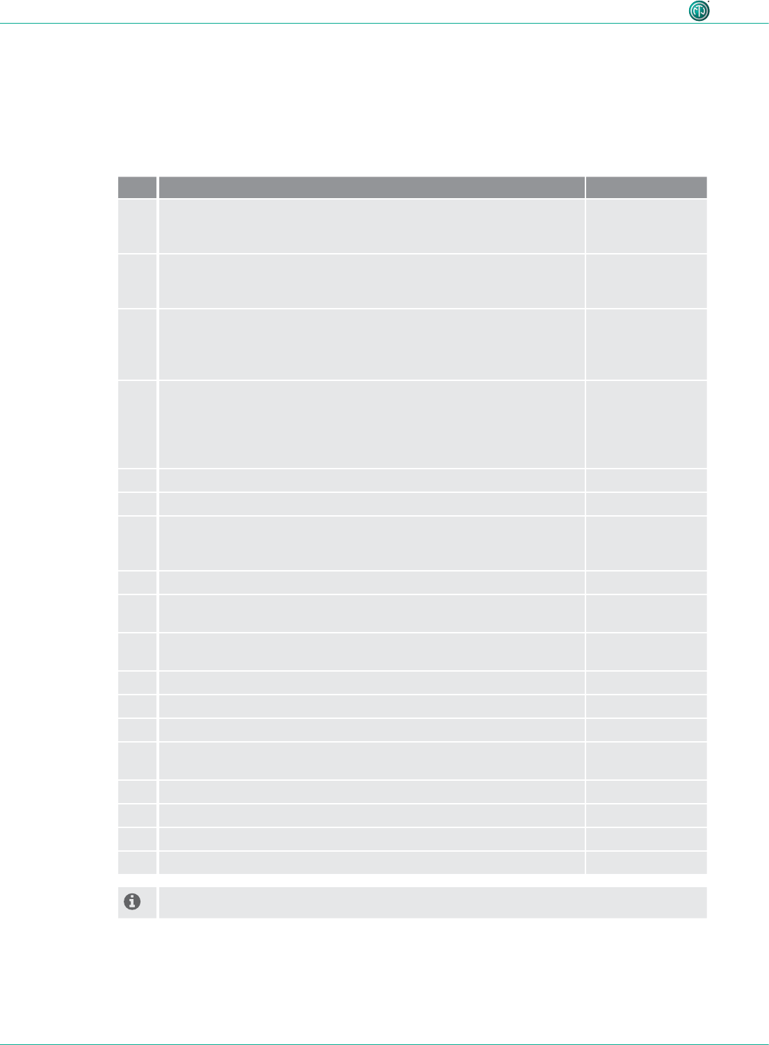
3.1 XIRIUM PRO components
The components and accessories are ordered individually.
2
13 14
15 16
17 18
1
78
3 4
10
11 12
9
5 6
12 User Manual – XIRIUM PRO® CA | BDA 471 2017/03
Components and accessories
* Quick Start Guide included in scope of delivery.
Pos. Description Article no.
1 TX base station*
(TX base station, XIRIUM PRO USB data cable, ManfrottoTM universal
mounting clamp, 5 GHz antenna, 2.4 GHz antenna)
NXP2TX-C
2 RX base station*
(RX base station, XIRIUM PRO USB data cable, ManfrottoTM universal
mounting clamp, 2.4 GHz antenna)
NXP2RX-C
3TX modules
•TX module analog*
•TX module AES*
•TX module DANTE*
NXP-TM-ANA
NXP-TM-AES
NXP-TM-DANTE
4RX modules
•RX module analog*
•RX module AES*
•RX module DANTE*
•Repeater module*
NXP-RM-ANA
NXP-RM-AES
NXP-RM-DANTE
NXP-RM-RP
5 5 GHz antenna 9 dBi 360°H 12.5°V NXPA-9-360-12.5
6 5 GHz antenna 6 dBi 360°H 25°V NXPA-6-360-25
7 5 GHz directional antenna 14 dBi 40°H 35°V, including adapter to
mount the antenna directly on a receiver if no repeater module is
inserted!
NXPA-14-40-35
8 2.4 GHz omnidirectional antenna for connecting app NXPA-WIFI
9 5 GHz directional antenna (for remte setup) 18 dBi 18°H 18°V, for
receiver if no repeater module is inserted! (cable not included!)
NXPA-18-18-18
10 5 GHz omnidirectional antenna 2 dBi 360°H 360°V, for repeater
setups with different antenna heights (see page 26)
NXPA-2-360
11 Antenna cable S04162B, N type connectors, 5 m, 4 dB attenuation NKXPA-5
12 N Adapter female female, for remote TX antenna (cable not icluded!) NXPA-N-FF
13 ManfrottoTM universal mounting clamp NXUC-M-15
14 Mounting arm for XIRIUM PRO antennas (NXPA-14-14-35, NXPA-18-
18-18, NX-6-360-25), compatible with ManfrottoTM clamp
NXPMA
15 Power cable XIRIUM PRO, 3 m NKXPF-5-15-3
16 XIRIUM PRO data cable NKXP-DATA
17 Flight case with foam cut-outs to hold 2x base stations (not included) CAS-NXP
18 Hard case (trolley) with foam cut-outs to hold 3 devices (not included) CAS-NXP-T
* Power cables have to be ordered seperately!
13User Manual – XIRIUM PRO® CA | BDA 471 2017/03
Description of product
11
66
78
22
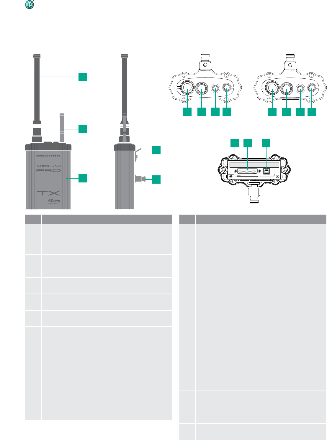
Pos. Designation
15 GHz antenna connector with 5 GHz
antenna
The antenna transmits the signals between the
XIRIUM PRO devices.
22.4 GHz antenna connector (reverse SMA)
with 2.4 GHz antenna
Transmits control data via WIFI
3Housing
Extruded aluminum housing
4Lug
Safety lug for additional fall arresting
5Bolt
Adapter for mounting with a ManfrottoTM clamp
6On/off switch
Powering the device ON/OFF, LED indication
LED display:
•LED off: Device off or powering up.
•LED solid green: Device powerd-on and battery
level is between 20 % and 100 %.
•LED slow-ash green: Device powerd-on and
battery is charging.
•LED solid red: Firmware update active.
•LED slow-ash red: Device identication
activated from app by pressing the Identify
Device button.
•LED quick-ash red: Battery below 20 %.
4 Description of product
4.1 XIRIUM PRO base station
ON/OFF LINK push 1s
XROC push 4s
ON/OFF LINK push 1s
DELAY push 4s
ON/OFF LINK push 1s
XROC push 4s
ON/OFF LINK push 1s
DELAY push 4s
TX, top view
Bottom view
RX, top view
Pos. Designation
7TX link button
Linking devices, switching XROC mode ON/OFF,
resetting transmission power
•Push and release: Start/stop LINK process
•Hold 4 sec: Toggle XROC mode ON/OFF
•Hold 8 sec: Reset transmission power
LED display:
•LED off: TX not transmitting audio signal.
•LED solid blue: TX transmitting audio signal.
•LED quick-ash blue: Device is activated for
linking process.
•LED slow-ash blue: XROC mode set to ON.
8RX link button
Linking devices; switching delay ON/OFF
•Push and release: Start/stop LINK process
•Hold 4 sec: Toggle delay ON/OFF
•Hold 8 sec: Reset repeater transmission power
LED display:
•LED off: RX not receiving audio signal.
•LED solid blue: RX receiving audio signal.
•LED quick-ash blue: Device is activated for
linking process.
•LED slow-ash blue: Delay set to ON.
9Type plate
With serial number, SSID and WLAN password
10 D-Sub connector
Interface between base station and module.
11 USB port
USB connection for rmware update
AES
RX
LIECHTENSTEIN
OUT
1 3 2
EBU
/
RX
LIECHTENSTEIN
LINE
OUT 1 (XROC) OUT 2
1 3 2 1 3 2
DANTE
C6
A
RX
LIECHTENSTEIN
OUT
C6
A
TX
LIECHTENSTEIN
IN
AES
1 2
3
EBU
/
PUSH
DANTE
C6
A
TX
LIECHTENSTEIN
IN
C6
A
REPEATER
RX
LIECHTENSTEIN
TX
LIECHTENSTEIN
IN 2
IN 1 (XROC)
LINE
1 2
3
PUSH
1 2
3
PUSH
100-240V~ 0.5A 50-60Hz
100-240V~ 0.5A 50-60Hz
100-240V~ 0.5A 50-60Hz100-240V~ 0.5A 50-60Hz100-240V~ 0.5A 50-60Hz
100-240V~ 0.5A 50-60Hz100-240V~ 0.5A 50-60Hz
1
2
3
4
5
10911
14 User Manual – XIRIUM PRO® CA | BDA 471 2017/03
Description of product
4.2 Modules
TX AES module
RX DANTE moduleRX analog module
Repeater module
RX AES module
TX DANTE moduleTX analog module
Top view Bottom view
4.2.2 RX modules
4.2.1 TX modules
AES
RX
LIECHTENSTEIN
OUT
1 3 2
EBU
/
RX
LIECHTENSTEIN
LINE
OUT 1 (XROC) OUT 2
1 3 2 1 3 2
DANTE
C6
A
RX
LIECHTENSTEIN
OUT
C6
A
TX
LIECHTENSTEIN
IN
AES
1 2
3
EBU
/
PUSH
DANTE
C6
A
TX
LIECHTENSTEIN
IN
C6
A
REPEATER
RX
LIECHTENSTEIN
TX
LIECHTENSTEIN
IN 2
IN 1 (XROC)
LINE
1 2
3
PUSH
1 2
3
PUSH
100-240V~ 0.5A 50-60Hz
100-240V~ 0.5A 50-60Hz
100-240V~ 0.5A 50-60Hz100-240V~ 0.5A 50-60Hz100-240V~ 0.5A 50-60Hz
100-240V~ 0.5A 50-60Hz100-240V~ 0.5A 50-60Hz
AES
RX
LIECHTENSTEIN
OUT
1 3 2
EBU
/
RX
LIECHTENSTEIN
LINE
OUT 1 (XROC) OUT 2
1 3 2 1 3 2
DANTE
C6
A
RX
LIECHTENSTEIN
OUT
C6
A
TX
LIECHTENSTEIN
IN
AES
1 2
3
EBU
/
PUSH
DANTE
C6
A
TX
LIECHTENSTEIN
IN
C6
A
REPEATER
RX
LIECHTENSTEIN
TX
LIECHTENSTEIN
IN 2
IN 1 (XROC)
LINE
1 2
3
PUSH
1 2
3
PUSH
100-240V~ 0.5A 50-60Hz
100-240V~ 0.5A 50-60Hz
100-240V~ 0.5A 50-60Hz100-240V~ 0.5A 50-60Hz
100-240V~ 0.5A 50-60Hz
100-240V~ 0.5A 50-60Hz100-240V~ 0.5A 50-60Hz
AES
RX
LIECHTENSTEIN
OUT
1 3 2
EBU
/
RX
LIECHTENSTEIN
LINE
OUT 1 (XROC) OUT 2
1 3 2 1 3 2
DANTE
C6
A
RX
LIECHTENSTEIN
OUT
C6
A
TX
LIECHTENSTEIN
IN
AES
1 2
3
EBU
/
PUSH
DANTE
C6
A
TX
LIECHTENSTEIN
IN
C6
A
REPEATER
RX
LIECHTENSTEIN
TX
LIECHTENSTEIN
IN 2
IN 1 (XROC)
LINE
1 2
3
PUSH
1 2
3
PUSH
100-240V~ 0.5A 50-60Hz
100-240V~ 0.5A 50-60Hz
100-240V~ 0.5A 50-60Hz100-240V~ 0.5A 50-60Hz100-240V~ 0.5A 50-60Hz
100-240V~ 0.5A 50-60Hz
100-240V~ 0.5A 50-60Hz
AES
RX
LIECHTENSTEIN
OUT
1 3 2
EBU
/
RX
LIECHTENSTEIN
LINE
OUT 1 (XROC) OUT 2
1 3 2 1 3 2
DANTE
C6
A
RX
LIECHTENSTEIN
OUT
C6
A
TX
LIECHTENSTEIN
IN
AES
1 2
3
EBU
/
PUSH
DANTE
C6
A
TX
LIECHTENSTEIN
IN
C6
A
REPEATER
RX
LIECHTENSTEIN
TX
LIECHTENSTEIN
IN 2
IN 1 (XROC)
LINE
1 2
3
PUSH
1 2
3
PUSH
100-240V~ 0.5A 50-60Hz
100-240V~ 0.5A 50-60Hz
100-240V~ 0.5A 50-60Hz
100-240V~ 0.5A 50-60Hz100-240V~ 0.5A 50-60Hz
100-240V~ 0.5A 50-60Hz100-240V~ 0.5A 50-60Hz
AES
RX
LIECHTENSTEIN
OUT
1 3 2
EBU
/
RX
LIECHTENSTEIN
LINE
OUT 1 (XROC) OUT 2
1 3 2 1 3 2
DANTE
C6
A
RX
LIECHTENSTEIN
OUT
C6
A
TX
LIECHTENSTEIN
IN
AES
1 2
3
EBU
/
PUSH
DANTE
C6
A
TX
LIECHTENSTEIN
IN
C6
A
REPEATER
RX
LIECHTENSTEIN
TX
LIECHTENSTEIN
IN 2
IN 1 (XROC)
LINE
1 2
3
PUSH
1 2
3
PUSH
100-240V~ 0.5A 50-60Hz
100-240V~ 0.5A 50-60Hz
100-240V~ 0.5A 50-60Hz
100-240V~ 0.5A 50-60Hz
100-240V~ 0.5A 50-60Hz
100-240V~ 0.5A 50-60Hz100-240V~ 0.5A 50-60Hz
AES
RX
LIECHTENSTEIN
OUT
1 3 2
EBU
/
RX
LIECHTENSTEIN
LINE
OUT 1 (XROC) OUT 2
1 3 2 1 3 2
DANTE
C6
A
RX
LIECHTENSTEIN
OUT
C6
A
TX
LIECHTENSTEIN
IN
AES
1 2
3
EBU
/
PUSH
DANTE
C6
A
TX
LIECHTENSTEIN
IN
C6
A
REPEATER
RX
LIECHTENSTEIN
TX
LIECHTENSTEIN
IN 2
IN 1 (XROC)
LINE
1 2
3
PUSH
1 2
3
PUSH
100-240V~ 0.5A 50-60Hz
100-240V~ 0.5A 50-60Hz
100-240V~ 0.5A 50-60Hz100-240V~ 0.5A 50-60Hz100-240V~ 0.5A 50-60Hz
100-240V~ 0.5A 50-60Hz
100-240V~ 0.5A 50-60Hz
AES
RX
LIECHTENSTEIN
OUT
1 3 2
EBU
/
RX
LIECHTENSTEIN
LINE
OUT 1 (XROC) OUT 2
1 3 2 1 3 2
DANTE
C6
A
RX
LIECHTENSTEIN
OUT
C6
A
TX
LIECHTENSTEIN
IN
AES
1 2
3
EBU
/
PUSH
DANTE
C6
A
TX
LIECHTENSTEIN
IN
C6
A
REPEATER
RX
LIECHTENSTEIN
TX
LIECHTENSTEIN
IN 2
IN 1 (XROC)
LINE
1 2
3
PUSH
1 2
3
PUSH
100-240V~ 0.5A 50-60Hz
100-240V~ 0.5A 50-60Hz
100-240V~ 0.5A 50-60Hz100-240V~ 0.5A 50-60Hz100-240V~ 0.5A 50-60Hz
100-240V~ 0.5A 50-60Hz100-240V~ 0.5A 50-60Hz
1
2
3
3 1 564
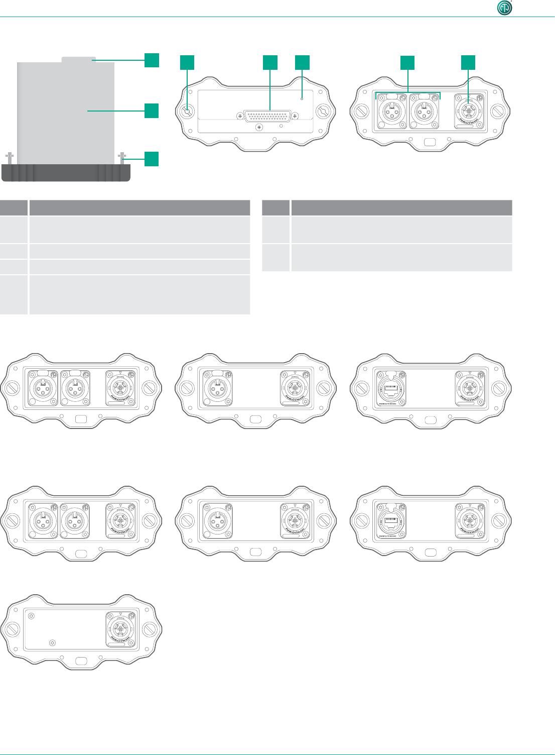
Pos. Description
1D-Sub connector
interface between base station and module
2Module with integrated battery
3Locking bolt
4LED charging indicator
•Flashes green: Battery charging.
•Lit green: Battery fully charged.
Pos. Description
5Audio IN (TX), audio OUT (RX)
(different connections depending on module)
6powerCON TRUE1 chassis
for XIRIUM PRO power cable
15User Manual – XIRIUM PRO® CA | BDA 471 2017/03
Description of product
4.3 XIRIUM PRO app
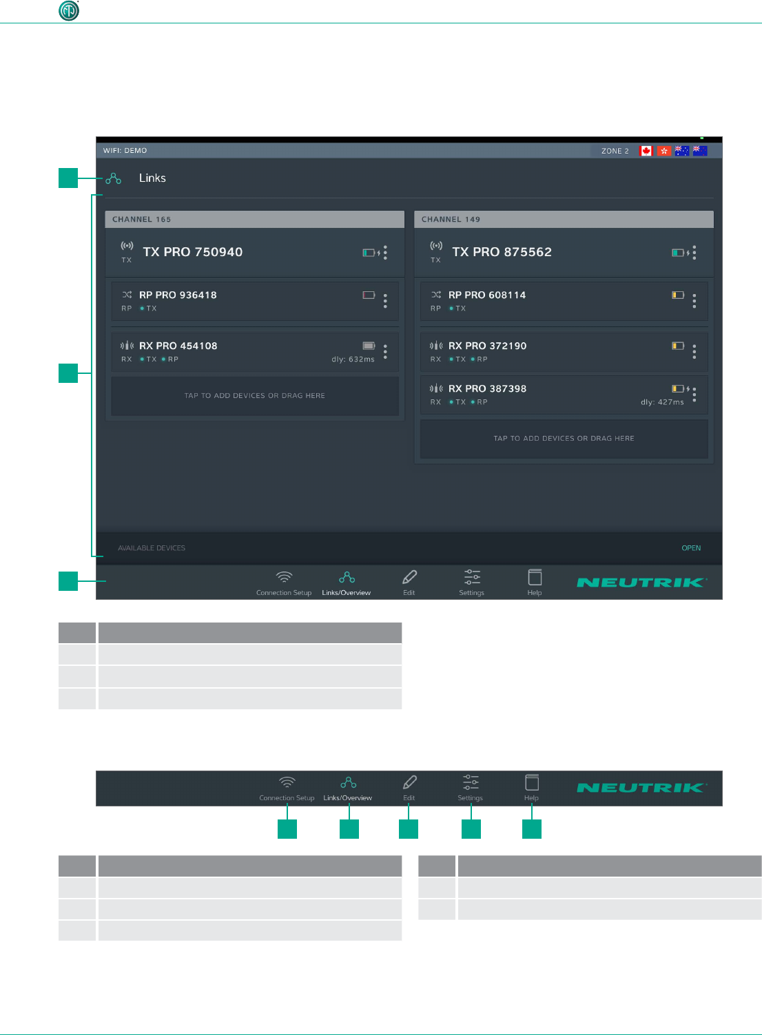
The XIRIUM PRO app enables convenient operation and control of the devices from a tablet.
4.3.1 Overview of operation elements
2
3
21 3 4 5
1
Pos. Description
1Page title
2Operation and display area
3 Navigation bar
Navigation bar
Pos. Description
1Connection setup button
2Links/Overview button
3Edit button
Pos. Description
4Settings button
5Help button
•Tapping a button opens the associated page.
•When the page is active, the pictogram is green and the text is white.
16 User Manual – XIRIUM PRO® CA | BDA 471 2017/03
Description of product
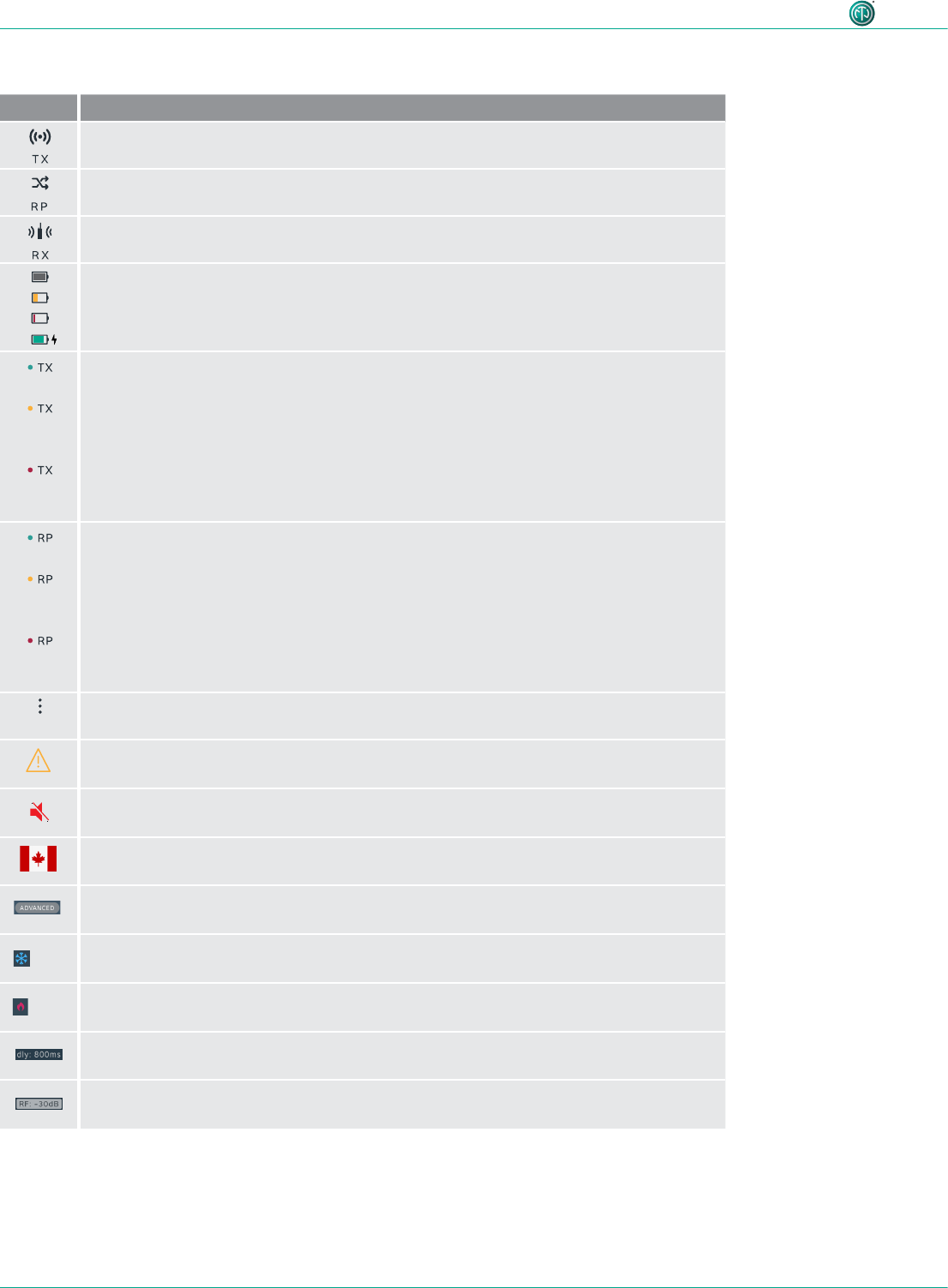
Symbols in the app
Symbol Description
The displayed device is a TX.
The displayed device is a RX with a repeater module.
The displayed device is a RX.
The battery level is between 40 % and 100 %.
The battery level is below 40 %.
The battery level is below 20 %. Connect the device to the mains supply.
Animated display: Battery is charging.
The signal quality received from the TX is good, which refers to a proper RSSI level and
a low packet loss.
The signal quality received from the TX is critical. This is either due to a critical
RSSI level or a critical packet loss.
On Edit page the signal quality bar is monitored in detail.
The signal quality received from the TX is bad. This is either due to a bad RSSI level or
a high packet loss.
On Edit page the signal quality bar is monitored in detail.
The signal quality received from the RP is good, which refers to a proper RSSI level and
a low packet loss.
The signal quality received from the RP is critical. This is either due to a critical
RSSI level or a critical packet loss.
On the Edit page the signal quality bar is monitored in detail.
The signal quality received from the RP is bad. This is either due to a bad RSSI level or
a high packet loss.
On the Edit page the signal quality bar is monitored in detail.
Display device options button
Tapping this button opens the options menu.
Indicates that a message with information is pending for this device. The information is
displayed in plain text on the Edit page of the selected device.
Mute icon: Indicates, if RX is muted
Zone indicator: Displays to which country settings the devices in use are programmed.
Advanced mode indicator: Displays, if advanced mode is switched ON.
LOW Device temperature is LOW.
HIGH Device temperature is HIGH.
Delay indicator: Indicates in the Links / Overview window if the delay on a RX is
switched on.
RF attenuation indicator: Indicates in the Links / Overview window if the RF
attenuation on a RX is switched on.
17User Manual – XIRIUM PRO® CA | BDA 471 2017/03
Description of product
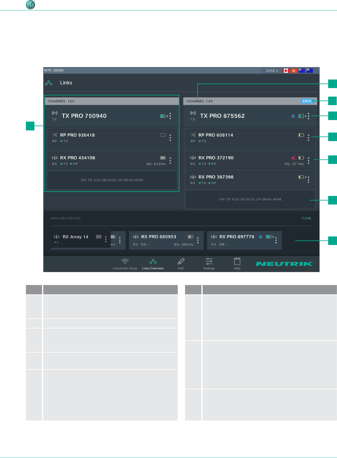
Pos. Description
1Transmission path
This grouping displays all devices that are in one
RF channel
2Transmission channel
3XROC indicator
Is displayed when XROC mode is active for the
RF channel
4TX display
1 TX is needed for each transmission path
5Repeater display
As an option, repeaters may be used.
A maximum 1 repeater per RF channel is possible.
•The display is highlighted in red when there is a
poor connection to the TX, or none at all.
Pos. Description
6RX display
Each eld represents one device.
A minimum 1 RX is needed for each transmission
path.
•The display is highlighted in red when there is a
poor connection to the TX, or none at all.
7Button for adding devices to transmission
path
•Add a device: Use drag&drop to add a device
from AVAILABLE DEVICES.
•Add several devices: Tap button and select
device from AVAILABLE DEVICES.
8AVAILABLE DEVICES
Displays all available devices which have not yet
been assigned to a transmission path.
Tapping OPEN/CLOSE opens/closes the display.
4.3.2 Links/Overview page
All devices that were added to the network via an access point are displayed on this page. The devic-
es are grouped according to transmission path. Each transmission path is assigned to one transmis-
sion channel. In stand-alone mode, the Links/Overview page is inactive.
3
2
4
5
6
7
8
1
18 User Manual – XIRIUM PRO® CA | BDA 471 2017/03
Description of product
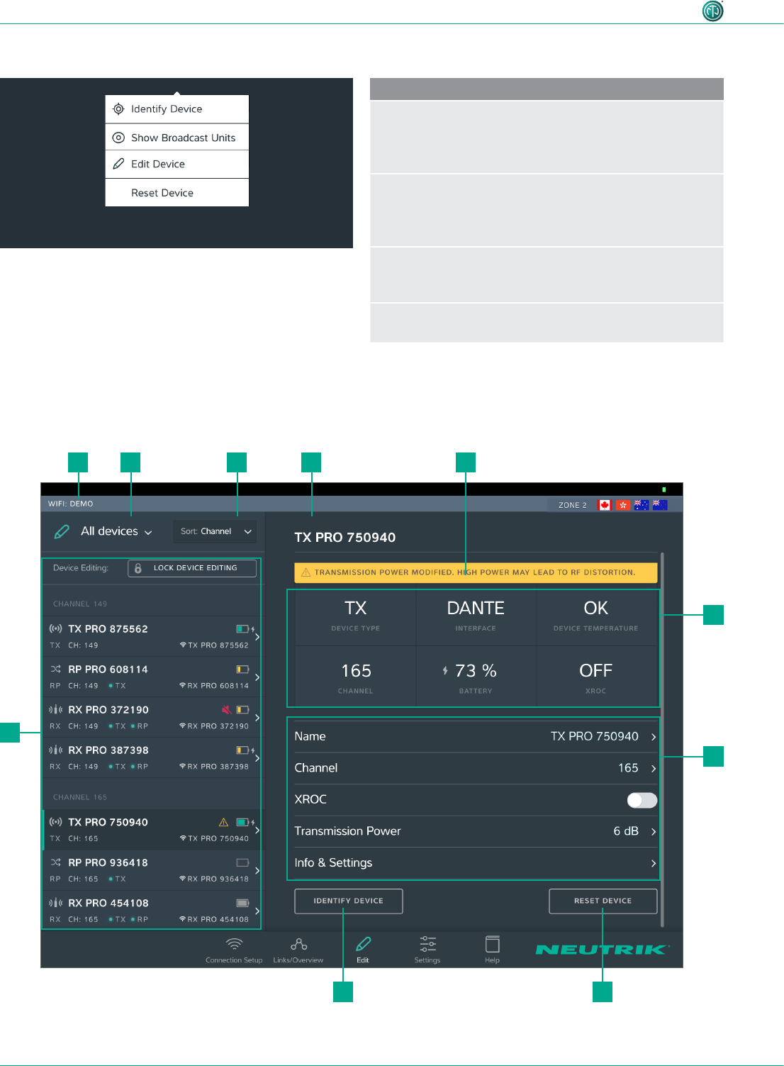
Device options menu
Description
Identify Device
Tap the button to identify a single device: The
power LED of the device slowly ashes red for about
10 seconds.
Show Broadcast Units
Tap the button: The power LEDs of all devices which are
assigned to the same channel slowly ash red for about
10 seconds.
Edit Device
Opens the Edit Device page so all properties of the
device can be edited.
Reset Device
Reset device properties to factory state
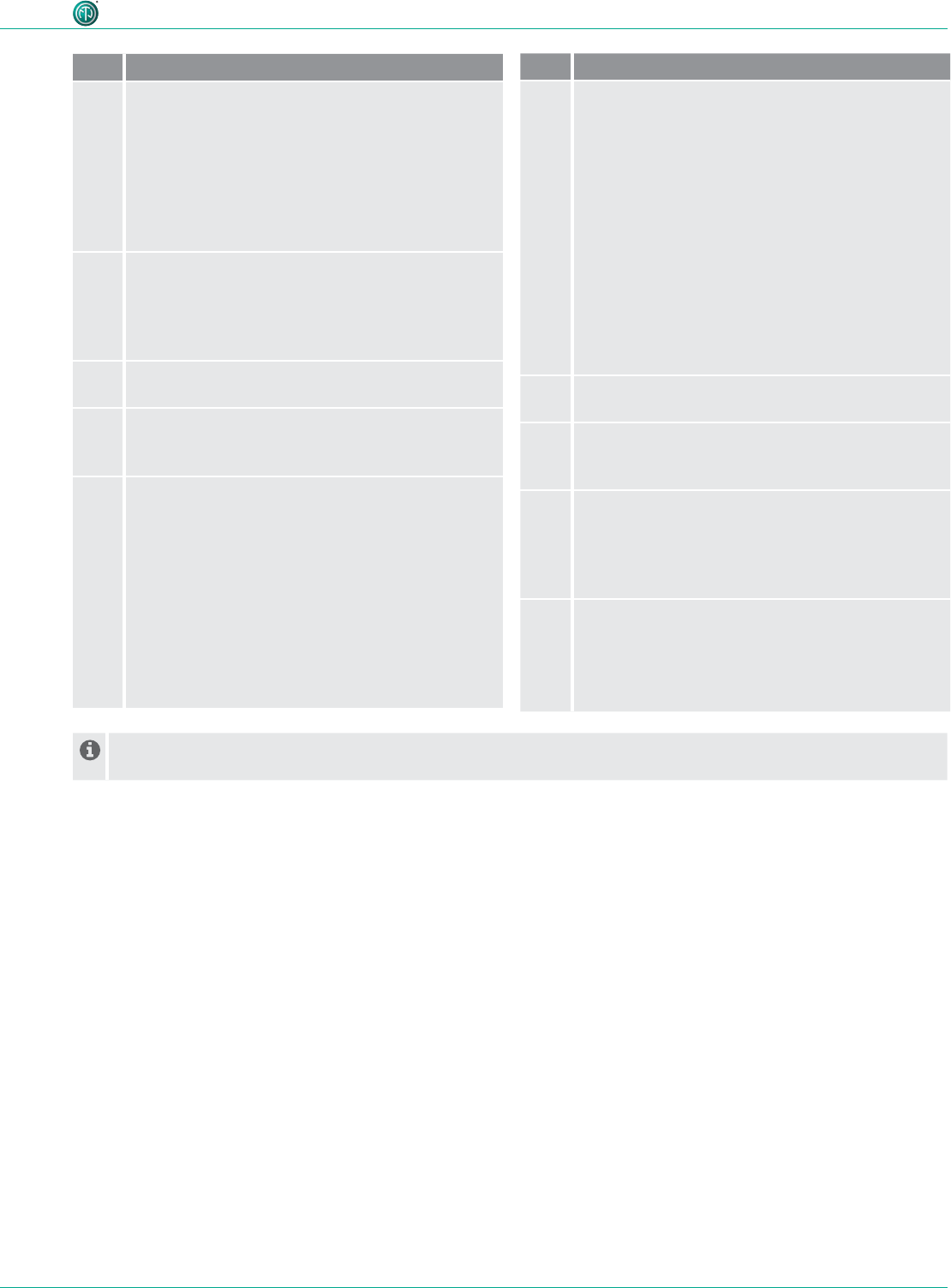
4.3.3 Edit page
Edit TX
9
5
6
110 2 3 4
78
19User Manual – XIRIUM PRO® CA | BDA 471 2017/03
Description of product
Pos. Description
1Filter devices drop-down menu
Only the devices that meet the lter criteria are
displayed.
•All Devices: List all devices.
•Low Battery: Only list devices on which the
battery is weak.
•Out of Range: Only list devices that receive a
poor signal, or none at all.
2Sorting drop-down menu
Species the criteria for sorting the devices.
•Channel: Devices are sorted according to
channel.
•Type: Devices are sorted according to type.
3Device Name
Displays the device name entered by the user.
4Note
Contains useful information for safe, trouble-free
operation.
5Device Properties
•Device Type: Device is a TX.
•Interface: Indicates the module being used.
•Device Temperature: Indicates the temperature
of the device (low, ok or high)
•Channel: Indicates the channel the device is
transmitting on.
•Battery: Indicates the battery charge status
in %.
•XROC: Indicates whether the XROC mode is
ON/OFF.
Pos. Description
6Adjustable properties
Tapping on a property opens the associated sub-
page.
•Name: Opens the page for changing the device
name.
•Channel: Opens the page for changing the
transmission channel.
•XROC: Tapping this button toggles the
XROC mode ON/OFF.
•Transmission Power: Opens the page for
adjusting the transmission power of the TX/
repeater.
•Info & Settings: Opens a page with information
about the device.
7Reset Device button
Resets the device to factory state.
8Identify Device button
The power LED of the device selected will slowly
ash for about 10 seconds.
9Overview of the connected devices
Lists all connected devices according the set lter
and sorting criteria.
The selected device is marked with a green bar
and a dark background.
10 Name of access point used
In standalone mode the Allow link button is shown on the Edit page. Tapping the Allow link button starts the
connection process of the TX.
20 User Manual – XIRIUM PRO® CA | BDA 471 2017/03
Description of product
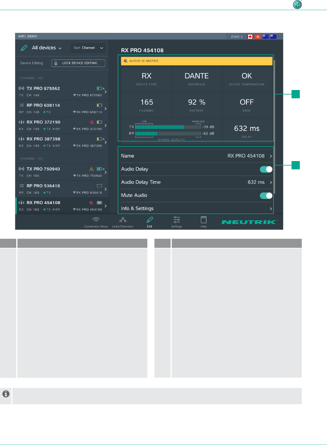
Edit RX
Pos. Description
1Device properties
•Device Type: Indicates that the device is an RX.
(for RX with repeater module: RP)
•Interface: Indicates the module being used.
•Device Temperature: Indicates the temperature
of the device (low, ok or high)
•Channel: Indicates the channel the device is
assigned to.
•Battery: Indicates the battery level in %.
•XROC: Indicates whether the transmission path
of the XROC mode is ON/OFF.
•Signal quality: Indicates the signal quality
of the signals received from the TX and/or
repeater. Signal quality is a combination of RSSI
Level and packet loss.
•Delay: Indicates the set delay time in
milliseconds, feet or meters, or indicates the
delay is off.
Pos. Description
2Settable properties
Tapping on a property opens the associated sub-
page.
•Name: Opens the page for changing the device
name.
•Audio Delay: Tap the button to activate/
deactivate the delay.
•Audio Delay Time: Opens the page for setting
the delay time.
•Mute Audio: Mutes this RX unit
•Info & Settings: Opens a page with information
about the device.
In standalone mode the Link button is shown on page Edit. Tapping the Link button links this RX to the TX.
1
2
21User Manual – XIRIUM PRO® CA | BDA 471 2017/03
Description of product
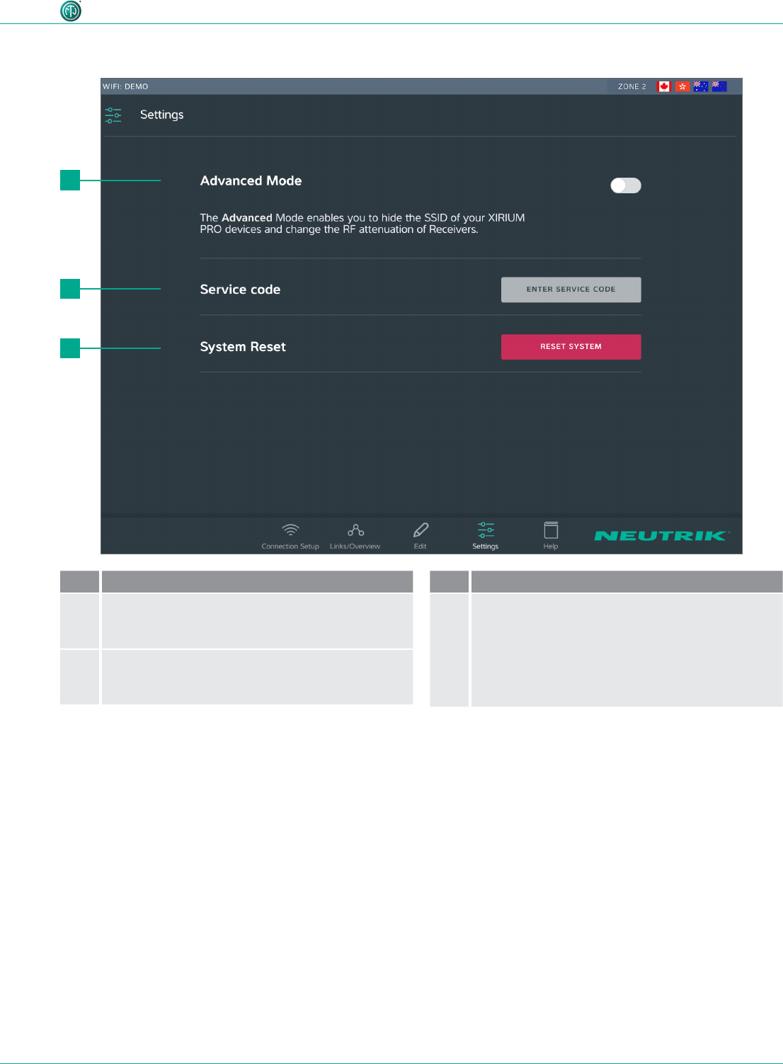
4.3.4 Settings page
Pos. Description
1Reset System button
Tapping this button opens a window with reset
options.
2Enter service code button
Opens entry eld for service code
(only for service personnel)
Pos. Description
3Reset System button
Tapping this button opens a window with reset
options.
2
3
1
22 User Manual – XIRIUM PRO® CA | BDA 471 2017/03
Description of product
2
1
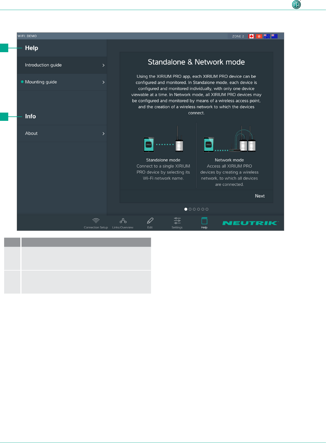
4.3.5 Help page
Pos. De scription
1Help
Useful information for a proper XIRIUM PRO
setup.
2Information about the software
Software Version: Version of the installed app.
Version Date: Date app was issued

23User Manual – XIRIUM PRO® CA | BDA 471 2017/03
Description of product
4.4 Getting started
The XIRIUM PRO system makes it possible to replace conventional cable connections between audio
sources and audio sinks (referred to in short as "peripheral devices" below) with a robust radio con-
nection.
With just 2 devices, the transmitter (TX) and the receiver (RX), an audio signal can be transmitted
quickly and cost-efciently. The XIRIUM PRO system transfers audio signals (LINE level) as well as
digital audio signals (AES or DANTE) in studio quality with an extremely low latency time.
9 channels in the 5 GHz band are available for transmitting the audio signal. Up to two audio signals
can be transmitted in one RF channel with no loss to audio quality. The distance between transmit-
ter and receiver can be more than 3200 feet.1 The actual distance between transmitter and receiver
depends on the specic environmental conditions (line of sight, obstacles in the link, reections,
external RF signals, etc.).
Depending on the distance between transmitter and receiver, the transmission power may be manu-
ally controlled using the associated app in order to ensure the RSSI level remains in the "green range".
In order to be able to establish a connection between TX and RX, the devices must be separated by
a distance of at least 10 feet (using 6 dBi antenna and transmission power set to -3 dB).
Channel Medium frequency
UNII-1 band Ch 36 5180 MHz Only allowed for indoor use with
23 dBm EIRP (200 mW)
2
Ch 40 5200 MHz
Ch 44 5220 MHz
Ch 48 5240 MHz
UNII-3 band Ch 149 5745 MHz Allowed for outdoor use with
36 dBm EIRP (4 W)
2
Ch 153 5765 MHz
Ch 157 5785 MHz
Ch 161 5805 MHz
Ch 165 5825 MHz
The XIRIUM PRO system has been designed with features to simplify use. Understanding these fea-
tures will be helpful before the system is put into operation.
1 This refers to one of the UNII-3 band channels only, since the lower channels of the UNII-1 band have a lower approved
transmission power.
2 The app takes care of the maximum EIRP setting as soon as you choose a different RF channel!
24 User Manual – XIRIUM PRO® CA | BDA 471 2017/03
Description of product
It is highly recommended to choose a 2.4 GHz channel according to prior agreement with
event management. Uncoordinated usage of the 2.4 GHz channel may lead to connectivity
issues in the 2.4 GHz transmission path due to high trafc. The audio transmission is not
affected by the 2.4 GHz transmission path!
4.4.2 Repeater
A "repeater" is an RX equipped with a repeater module. The repeater is used in the following situ-
ations:
•Stabilizing transmission paths
The repeater receives the signal from the TX and transmits a redundant signal to the RX. The
redundant signal stabilizes the connection and reduces efferts caused by interferences.
•Overcoming obstacles
If no line-of-sight connection is possible, obstacles such as walls, glass or even corners can be
overcome with the repeater.
•Extending distances
When a repeater is used, the distance between TX and RX can be doubled.
OVERLOADLOW
-80 -60 -28 -25
4.4.3 Signal quality bar
The signal quality bar displays both RSSI level and packet loss. The scale of the bar refers to the RSSI
level (Received Signal Strength Indicator). It is recommend to have an RSSI level not appearing in the
“low” and “overload” area.
The color of the bar displays the packet loss:
•Bar is displayed green: packet loss is low
•Bar is displayed orange: packet loss is critical
•Bar is displayed red: packet loss is high.
A high packet loss increases the probability of losing audio.
4.4.1 App
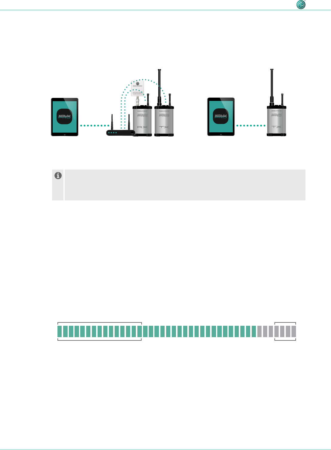
The app is the central control interface of the XIRIUM PRO system. Using the app, transmission paths
and networks can be created and managed. The app provides information about the current status
of the connected devices and transmission paths. The XIRIUM PRO devices can be connected to the
app through 2 modes:
Stand-alone mode
Only 1 device is directly connected
to the app.
Network mode
Several devices connected to the app via an
access point.
25User Manual – XIRIUM PRO® CA | BDA 471 2017/03
Description of product
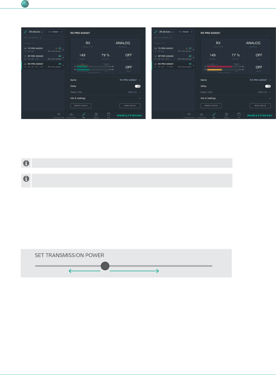
An improper RSSI level can be modied by increasing or decreasing the transmission power.
If the packet loss is high, the position of the devices have to be modied. Double-check if
there are other devices operating on the some channel and change the RF channel.
•RSSI level received from the TX is critical.
•The packet loss received from TX and RP is low.
We recommend to increase the transmission power of
the TX.
•RSSI level received from TX and RX are OK
•The color of the bars indicate a high (TX) and a critical
(Repeater) packet loss.
We recommend to relocate the devices and / or change
the RF channel.
Examples
4.4.4 Transmission power
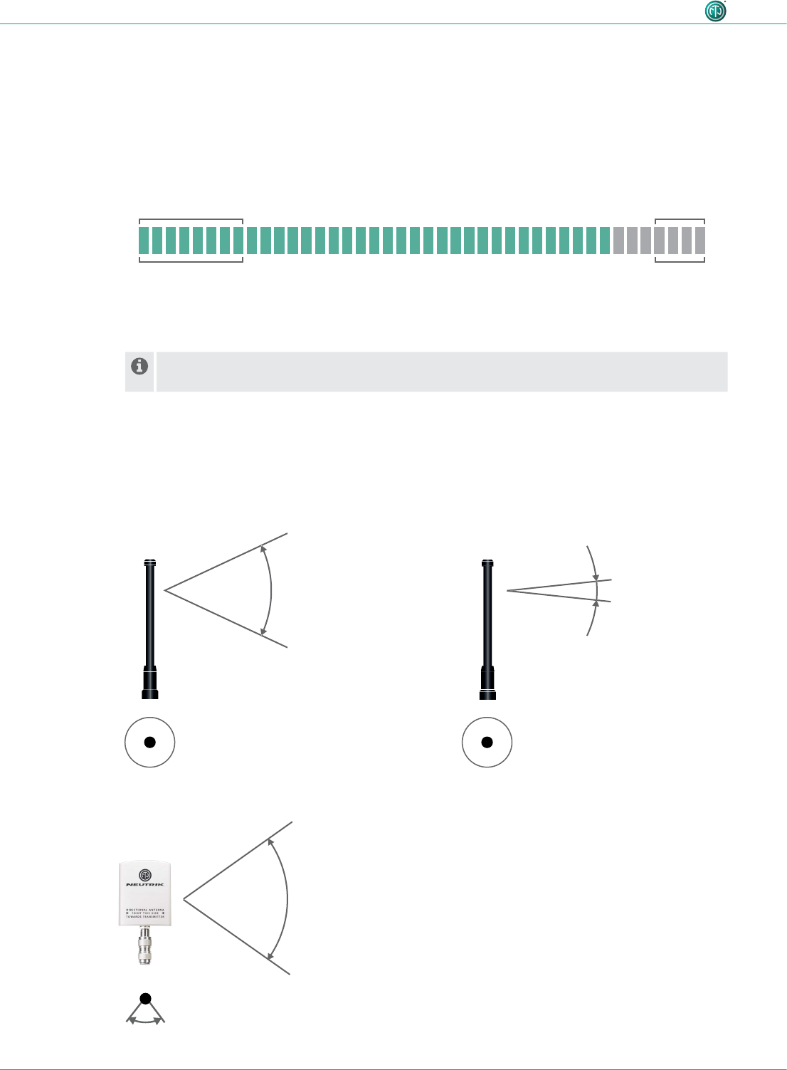
Depending on the application, the transmission power should be adjusted with the app so the RSSI
level on the receiver remains in the recommended range. However, the 10-foot minimum distance
between the TX/RX must always be maintained. This minimum distance applies when the 6 dBi an-
tenna and a transmission power of -3 dB are used. If the 9 dBi antenna and/or a higher transmission
power are used, the minimum distance increases.
Decreasing transmission power
In indoor areas and over short
distances.
Increasing transmission power
In outdoor areas and over longer distances.
26 User Manual – XIRIUM PRO® CA | BDA 471 2017/03
Description of product
4.4.5 XROC mode
If only 1 audio signal per RF channel is needed, we recommend using XROC mode. XROC stands for
"Extreme Ruggedized One Channel“. In XROC mode, only 1 audio signal at 6 Mbit/s is available for
each RF channel. The connection between the devices is much more stable in XROC mode, because
external inuences do not interfere with the RF signal between the XIRIUM PRO devices as much.
External inuences include strong reections of the RF signal in a room or from buildings, or external
signals. The power consumption of the devices is higher in XROC mode.
The increase in the performance range is illustrated in the RX signal quality bar, which displays a
smaller “low” area when XROC mode is used.
If XROC mode is enabled on a TX, only audio channel 1 is being transmitted. Therefore a
linked RX will have no audio on channel 2.
OVERLOAD
-80 -70 -28 -25
LOW
4.4.6 Antennas
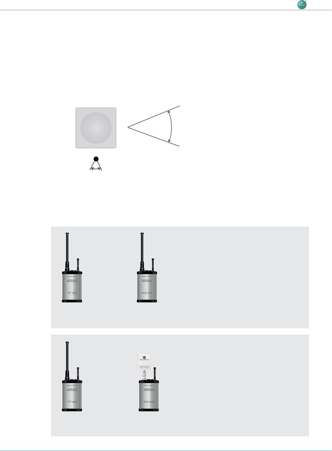
XIRIUM PRO uses omnidirectional antennas with xed vertical radiating angles. Neutrik offers two
different antennas: the standard 6 dBi antenna, featuring a 25° vertical angle, and an optional
9 dBi antenna with a 12.5° vertical angle.
6 dBi 9 dBi
25° vertical
360° horizontal 360° horizontal
12.5° vertical
14 dBi
40° horizontal
35° vertical
For pure receivers!
For pure receivers Neutrik recommends to use
a directional antenna. It helps focusing on the
TX signal and avoids disturbances from other
systems. There's an N-type adapter provided with
the antenna to mount it directly on the device.
27User Manual – XIRIUM PRO® CA | BDA 471 2017/03
Description of product
For receiver with a repeater module inserted!
2 dBi
360° horizontal
360° vertival
Not correct positioning
Correct positioning
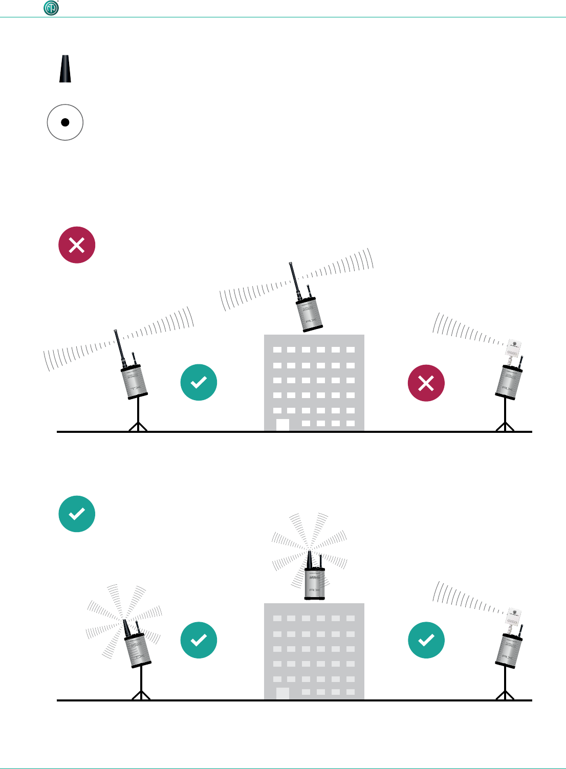
The 2 dBi omnidirectional antenna should be used
for applications where a parallel alignment of the
TX - RX antenna on the same height can't be es-
tablished.
Due to a lower antenna gain, the transmission range
is less.
28 User Manual – XIRIUM PRO® CA | BDA 471 2017/03
Description of product
18 dBi (NXPA-18-18-18)
18° horizontal
18° vertical
For pure receivers as a remote antenna.
NXPA-6-360-25
or NXPA-9-360-12.5
NXPA-6-360-25
or NXPA-9-360-12.5
NXPA-6-360-25
or NXPA-9-360-12.5
NXPA-14-40-35
4.4.7 Remote antennas
If the 5 GHz antenna and the 2,4 GHz antenna need to be aligned differently in terms of angle, it’s
advisable to remote the 5 GHz link. For that purpose Neutrik offers an antenna cable (NKXPA-5) with a
length of 5 meters and an attenuation of 4 dB. There is also an additional directional antenna available
for such applications having a gain of 18 dBi. This antenna must be used only for pure receivers and
not for any transmitting device, hence also not for a repeater. Like all other XIRIUM PRO antennas this
antenna has a vertical polarization. It is necessary to gear this antenna in the correct angle towards
the TX antenna. A correspondent graphical indication can be found on the backside of the antenna.
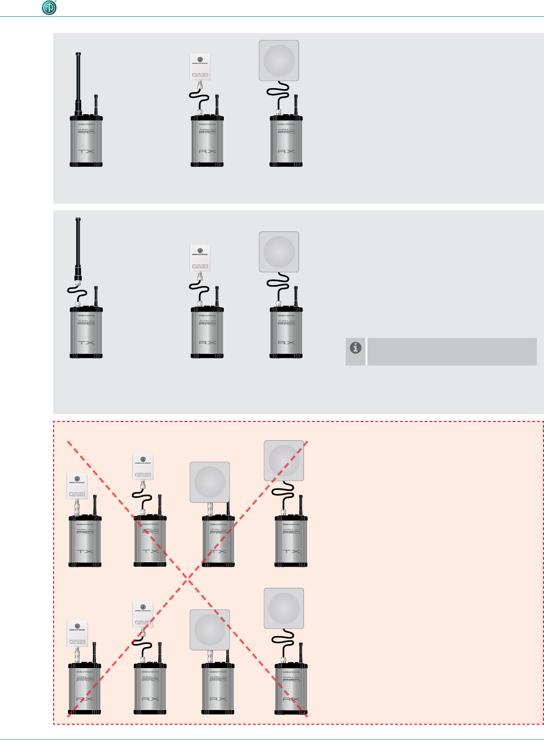
4.4.8 Antenna combinations
These are possible antenna combinations for the XIRIUM PRO system:
•common setup
•point-to-multipoint
•setup with directional antenna on RX
•point-to-multipoint
•Focusing on the TX signal and avoid
disturbances from other systems
29User Manual – XIRIUM PRO® CA | BDA 471 2017/03
Description of product
NXPA-6-360-25
or NXPA-9-360-12.5
NKXPA-5
NXPA-N-FF
NXPA-6-360-25
or NXPA-9-360-12.5
Transmitter
Repeater
NKXPA-5
NXPA-14-40-35
NKXPA-5
NXPA-14-40-35
NKXPA-5
NXPA-18-18-18
NKXPA-5
NXPA-18-18-18
or
or
•remote setup on RX
•point-to-multipoint
•different alignment of 2,4 GHz- and 5 GHz
antenna required
•remote setup on TX + RX
•point-to-multipoint
•Option to mount the antennas outdoor
and keep the devices indoor due to
temperature reasons (< 0°C / > 50°C)
•Shorter range than with the other setups
For a remote setup of the TX antenna
an adapter (NXPA-N-FF) is required.
Note!
Due to RF regulations it’s not allowed
to use the directional antennas on a
transmitter or repeater!
30 User Manual – XIRIUM PRO® CA | BDA 471 2017/03
Description of product
4.4.9 Line-of-sight and redundant RF path
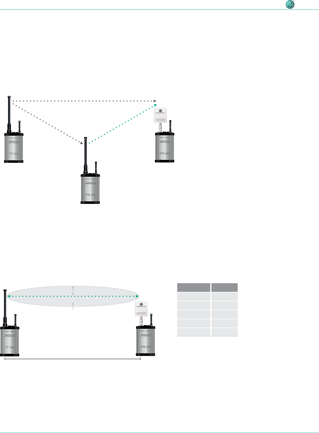
For a reliable wireless audio link, make sure all XIRIUM PRO devices have a line-of-sight connection.
If a line-of-sight connection cannot be established, the receiver may be in a drop-out zone. A drop-
out zone is a point where phase cancellation occurs between the direct signal and the deected one.
Relocating the transmitter (TX) and/or receiver (RX) can help eliminate this phase anomaly. Using a
repeater can also eliminate the problem of the drop out zone. A repeater effectively provides a re-
dundant RF path to all receivers within range. The RX receives identical audio signals from both the
transmitter and repeater.
distance d radius r
150 ft 2.7 ft
300 ft 3.8 ft
900 ft 6.6 ft
1500 ft 8.5 ft
3000 ft 12 ft
4.4.10 Antenna height + distance
Consider the Fresnel zone, which is an ellipsoidal area between wireless devices. For XIRIUM PRO
TX and RX devices, there should be no obstacles within the Fresnel zone. Maintaining proper
antenna height is essential to ensure trouble-free communication between XIRIUM PRO devices. To
dene an area that is free of obstacles, use the following chart to estimate proper antenna height.
Transmitter signal Identical audio signal
from two different
sources = redundancy
Repeater
signal
RX with repeater module
distance d
radius r
Fresnel zone

31User Manual – XIRIUM PRO® CA | BDA 471 2017/03
Description of product
4.5 Selecting transmission channels
4.5.1 Automatic selection of transmission channels
A TX is assigned to channel 149 by default. If channel 149 is already occupied by a different TX, the
device searches for the next free channel. The TX saves the last channel used. When switched on
again, the TX uses the last channel used, as long as it is not occupied. If the TX changes the channel,
all devices in the transmission path are assigned to the new channel.
4.5.2 Manual selection of transmission channels
The transmission channel can also be manually adjusted with the app. To guarantee a trouble-free
process, the app prevents an adjacent channel from being selected. The transmission channel can
be changed on the Edit page. More information in Section "Changing the transmission channel"
on page 40.