Neutrik XPT Digital Wireless Audio Transmitting Unit (TX) User Manual part 2
Neutrik AG Digital Wireless Audio Transmitting Unit (TX) part 2
Neutrik >
Contents
- 1. User manual
- 2. User Manual part 1
- 3. User Manual part 2
- 4. User Manual
User Manual part 2
32 User Manual – XIRIUM PRO® CA | BDA 471 2017/03
Operation
5 Operation
5.1 Setting devices into operation
Preparation
cUnpack all parts.
cSave packaging for later transport and storage.
cCheck the contents of the package for visible damage.
cWhen visible damage to the packaging and/or delivered
parts is detected:
Contact the salesperson or Neutrik sales partner.
cDo not use damaged devices under any circumstances.
CAUTION
Danger of damage to hearing!
Signal peaks may occur when an audio
source or sink is connected.
cBefore making connections, mute the
signal path of the peripheral devices.
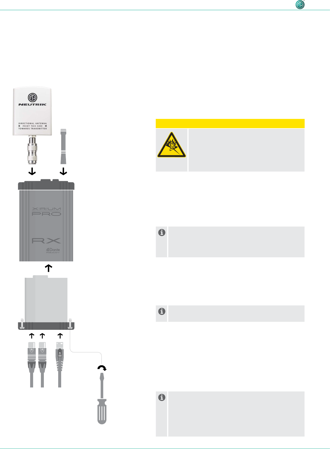
Putting together the device
cScrew the antennas tightly to the base station.
cInsert the module into the base station.
cSecure the module in the base station:
Using a straight screwdriver, turn the locking pin 1/4
rotation.
The XIRIUM PRO system can be used as a signal
converter.
Depending on the module used, an analog signal
can be converted to a digital signal, for example.
cConnect the device to the mains supply with a
powerCON TRUE1 plug.
As soon as the device is connected to the mains supply
500mA will be used to charge the module.
c
Depending on the application, battery runtime of
the device is up to 10 hours.
Switching the device ON/OFF
cSwitch the device on:
Push ON/OFF switch.
(The device powers up.
(After about 5 seconds, the power LED lights green.
cSwitch the device off:
Push ON/OFF switch.
These settings remain saved after the device is
switched off:
TX: Transmission channel, transmission power level,
XROC mode
RX: MAC address of the linked TX, all delay
settings, transmission power level (if a repeater)
33User Manual – XIRIUM PRO® CA | BDA 471 2017/03
Operation
5.2 Setting up the transmission path
It is also possible to set up a simple transmission path without the app. Using the app to set the
parameters is recommended.
The following components are needed to set up a simple transmission path:
^1 TX with module
^At least 1 RX with module
^Optional: 1 RX with repeater module
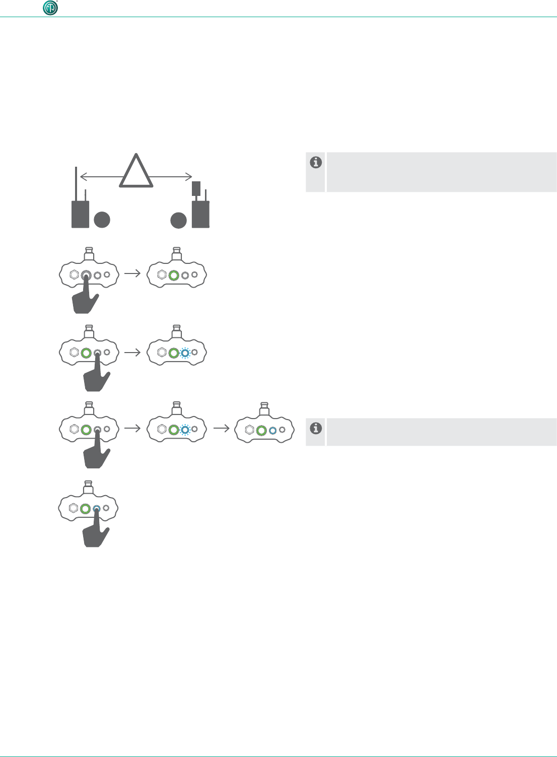
Because of the signal strength, the minimum
distance of 10 feet between TX and RX must be
maintained for the connection process.
cSwitch on TX and RX.
cStart the linking process on the TX:
Briey push the link button.
(The TX link LED ashes blue.
cStart the linking process on the RX:
Briey push the link button.
(The RX link LED briey ashes blue.
(The RX link LED lights solid blue as soon as the
connection to the TX is established.
cAdditional RX devices can be added to the transmission
path in the same way.
cEnd the linking process on the TX manually:
Briey push the link button.
(The TX link LED lights solid blue.
If the connection process is not ended manually on
the TX, it is automatically ended after 10 minutes.
TX + RX
TX
TX
RX
TX RX
!
min. 10 ft.
34 User Manual – XIRIUM PRO® CA | BDA 471 2017/03
Operation
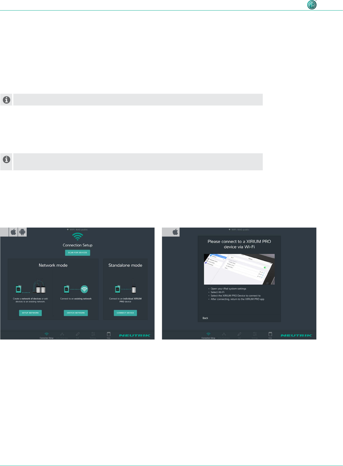
cStart the XIRIUM PRO app.
(The Connection Setup page appears.
cUnder Standalone Mode, tap Connect Device.
cExit the app.
cOn the iPad, open Settings > WLAN.
cConnect the iPad with the XIRIUM PRO device.
cSwitch back to the app.
(The app connects to the device.
1
5.3 Installing and starting the app
The XIRIUM PRO app is available at no cost from the Apple App Store and the Google Play Store.
cStart the app:
Tap the XIRIUM PRO icon.
The Introduction Guide is displayed when the app is started. This guide provides a quick overview of
the XIRIUM PRO system.
The Introduction Guide can be called up through the Help page at any time.
5.4 Connecting devices with the app
Each device has its own SSID name and its own WLAN password.
The SSID name and WLAN password are found on the type plate inside each device and on
the warranty card.
5.4.1 Connecting devices in stand-alone mode
In stand-alone mode, the XIRIUM PRO device is connected directly with the app.
^The app is installed on the iPad/Android tablet.
^The XIRIUM PRO device is switched on and ready to operate.
2a
35User Manual – XIRIUM PRO® CA | BDA 471 2017/03
Operation
2b
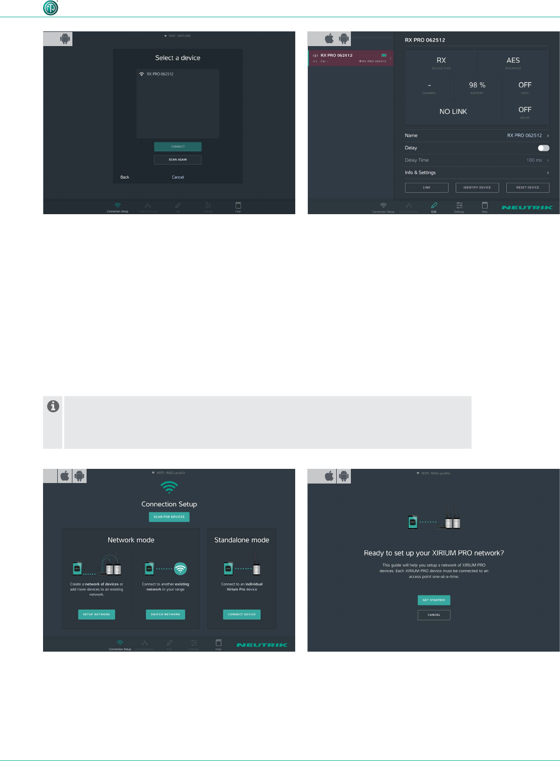
cSelect the XIRIUM PRO device from the selections.
cTap the Connect button.
(The app connects itself with the selected device.
5.4.2 Connecting devices in network mode
In network mode, the XIRIUM PRO devices are connected to the app via a WLAN access point. The
transmission paths are set up and congured with the app.
^The app is installed on the iPad.
^The XIRIUM PRO devices are switched on.
^A 2.4 GHz WLAN access point is available and ready to operate.
WLAN access points, which work in both the 2.4 GHz and the 5 GHz band ranges, are
disrupted by the signal of the XIRIUM PRO devices in the 5 GHz range.
cTherefore, deactivate the 5 GHz band range on the access point.
cPlease observe the details in chapter "8.2 Access point settings" on page 55.
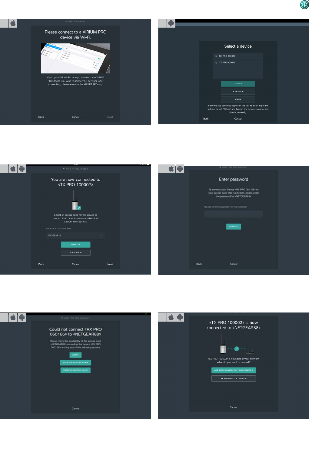
cStart the wizard:
Under Network mode, tap Setup Network.
cSet up network:
Tap Get Started! button.
12
3
(The device is connected in standalone mode.
36 User Manual – XIRIUM PRO® CA | BDA 471 2017/03
Operation
cExit the app.
cOn the iPad, open Settings > WLAN.
cConnect the iPad with the XIRIUM PRO device.
cWait for the tick after selecting a device before returning to
the app.
cSwitch back to the app.
3a 3b
cSelect the access point Available Access Points from the
drop-down menu.
cTap the Connect button.
cEnter the WLAN password of the access point.
cTap the Connect button.
cIf password is incorrect:
cTap Enter Password Again button.
(The device is connected with the access point.
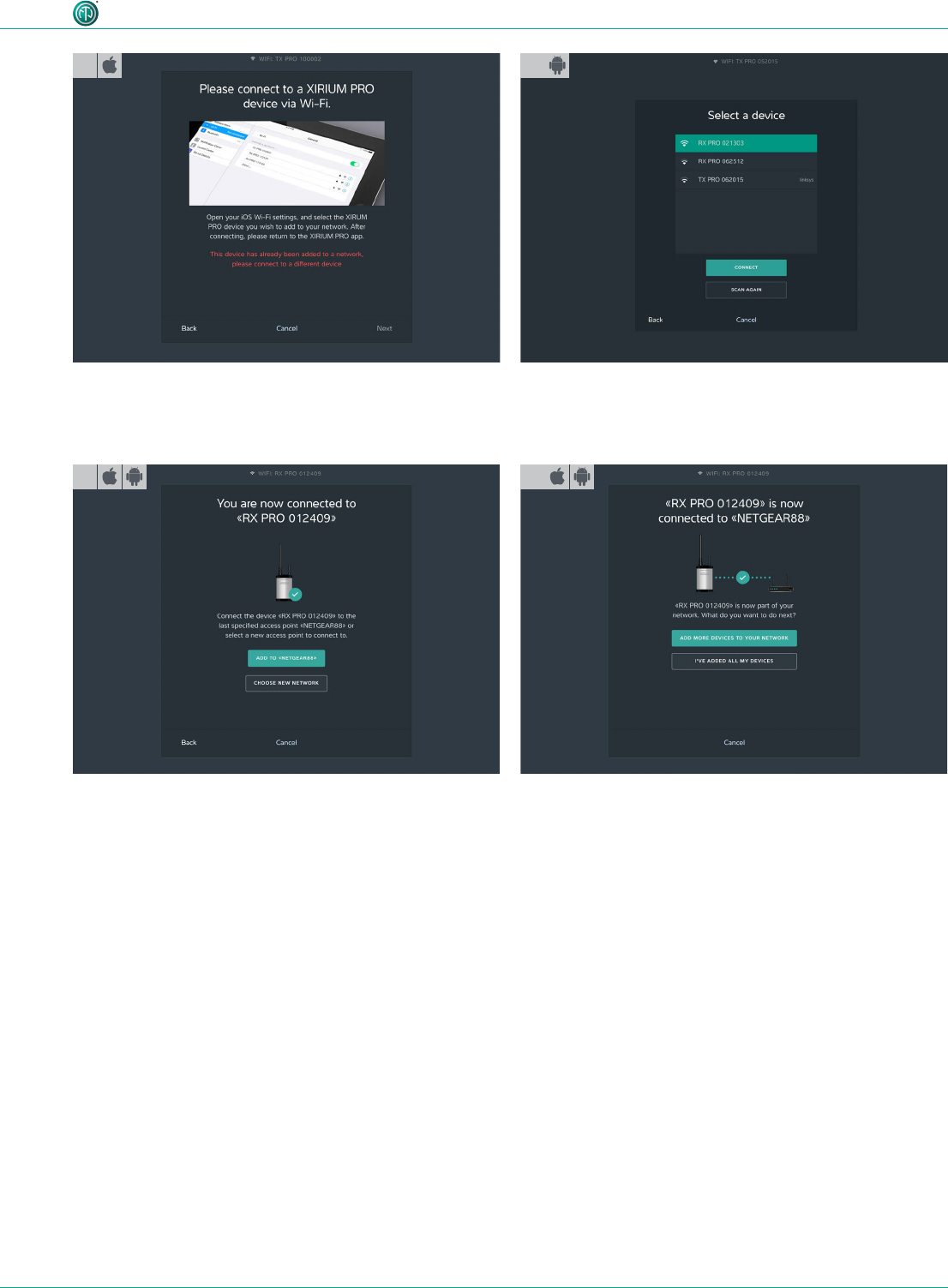
Add additional device:
cTap the Add More Devices To Your Network button.
cExit the app.
cOn the iPad, open Settings > WLAN.
5
5a 6
cSelect the XIRIUM PRO device from the selections.
cTap the Connect button.
(The app connects itself with the selected device.
(The app searches for available access points.
4
37User Manual – XIRIUM PRO® CA | BDA 471 2017/03
Operation
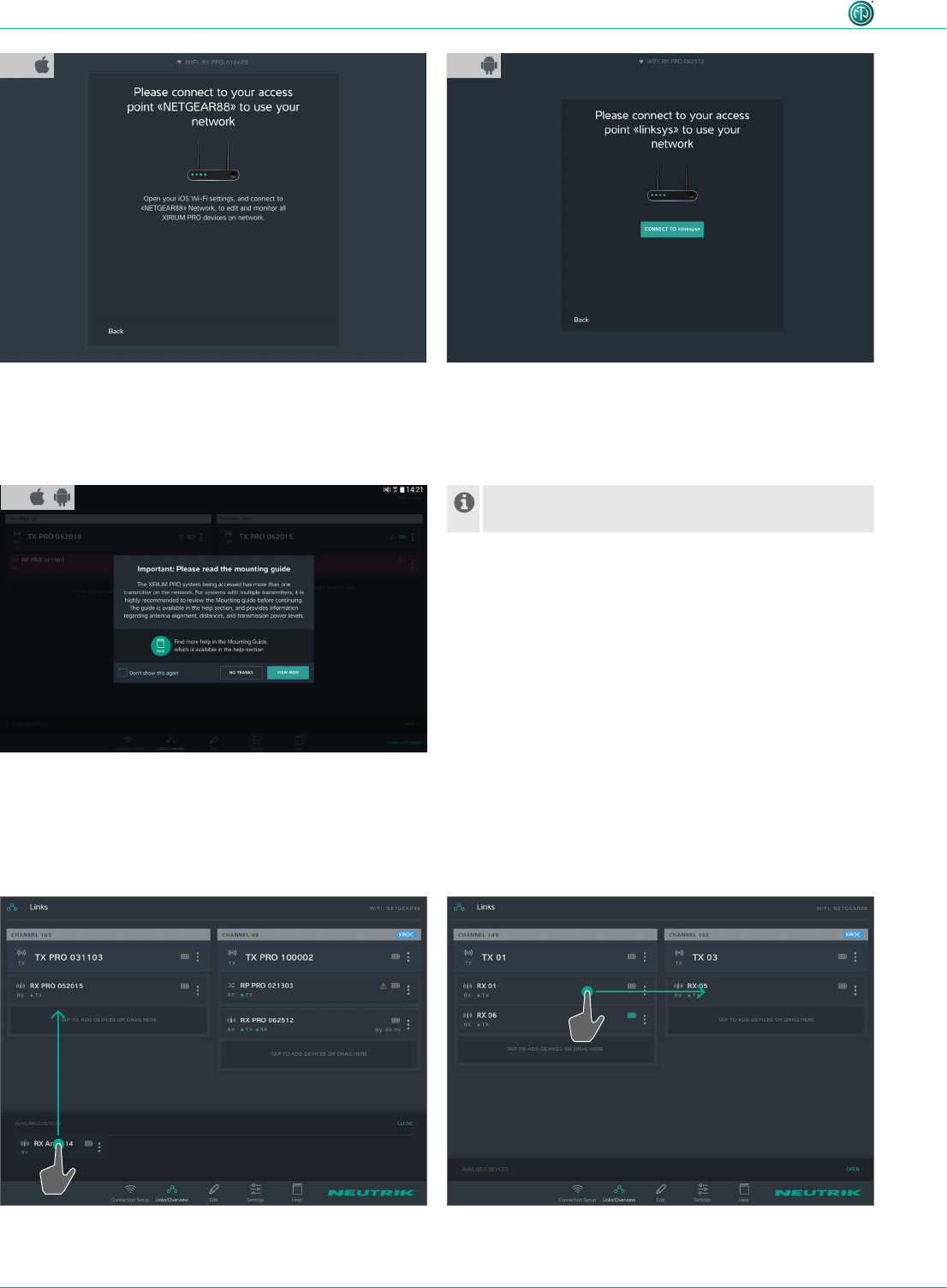
cConnect the iPad with the XIRIUM PRO device.
cSwitch back to the app.
cSelect the XIRIUM PRO device from the available
devices.
7a7
8
Add a device to a new network:
cTap the Choose New Network button.
cContinue with step 3.
cAdd additional devices to the network:
Tap the Add More Devices To Your Network button.
9
cAfter all devices have been added:
Tap the I've added all my devices button.
cExit the app.
cOn the iPad, open Settings > WLAN.
(Tap the Connect button. The app connects itself with
the selected device.
Add a device to the network:
cTap Add to «Access Point Name» button.
38 User Manual – XIRIUM PRO® CA | BDA 471 2017/03
Operation
5.5 Arranging the radio transmission path
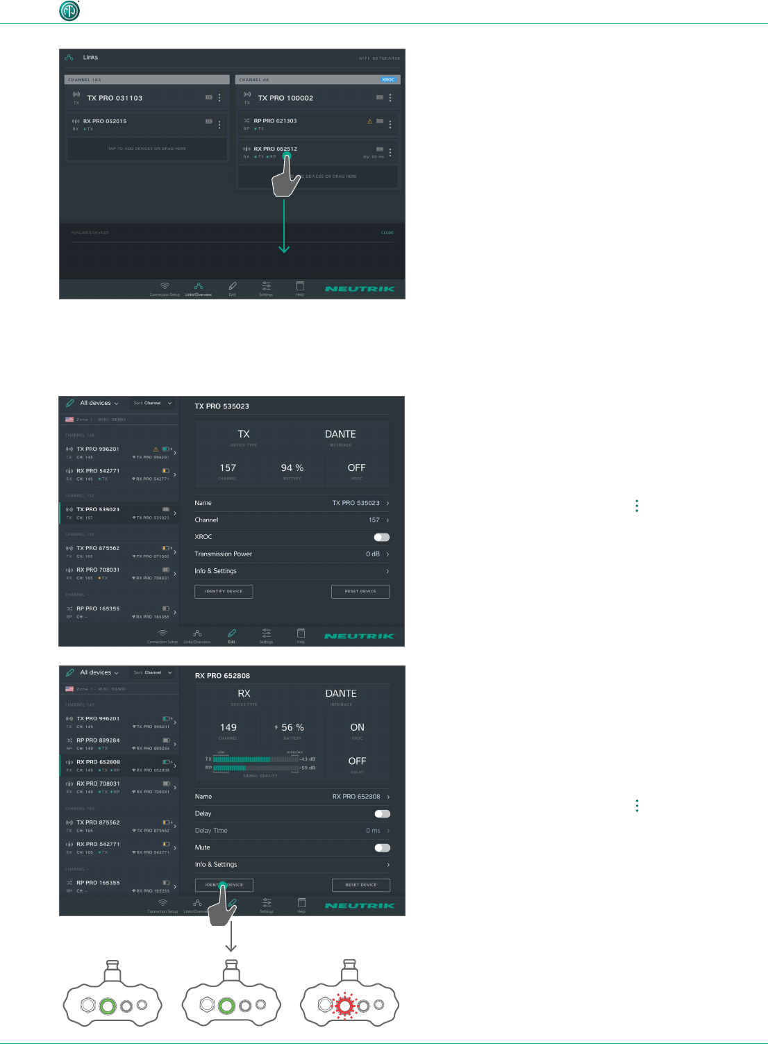
cAdd an available device to a transmission path:
Under Available Devices, use drag&drop to add the
device to the transmission path.
cAdd a device to a different transmission path:
Tap the device and drag it to the desired transmission
path.
11 Additional devices can be added at any time
through the Connection Setup page.
10a 10b
cConnect the iPad with the access point.
cSwitch back to the app.
(The network has been set up.
(If several TXs are connected with the app:
Reference to the Mounting Guide opens.
cConnect tablet to access point:
Tap Connect to «Access Point Name» button.
(Tablet connects itself with access point.
(The network has been set up.
(If several TXs are connected with the app:
Reference to the Mounting Guide opens.
39User Manual – XIRIUM PRO® CA | BDA 471 2017/03
Operation
cRemove a device from a transmission path:
Tap the device and drag it to Available Devices.
5.6 Configuring the device parameters
The devices are mainly controlled through the app.
Selecting the device to edit
Option 1:
cTap the device on the Links/Overview page.
Option 2:
cOn the Links/Overview page, tap at the device.
cIn the options menu, tap Edit.
Option 3:
cOn the Edit page, select the device from the list.
(The device is selected on the Edit page.
Identifying the device via the app
Option 1:
cOn the Edit page, tap the Identify device button.
(The power LED on the selected device ashes slowly for
a few seconds.
Option 2:
cOn the Links/Overview page, tap at the device.
cIn the options menu, tap Identify device.
40 User Manual – XIRIUM PRO® CA | BDA 471 2017/03
Operation
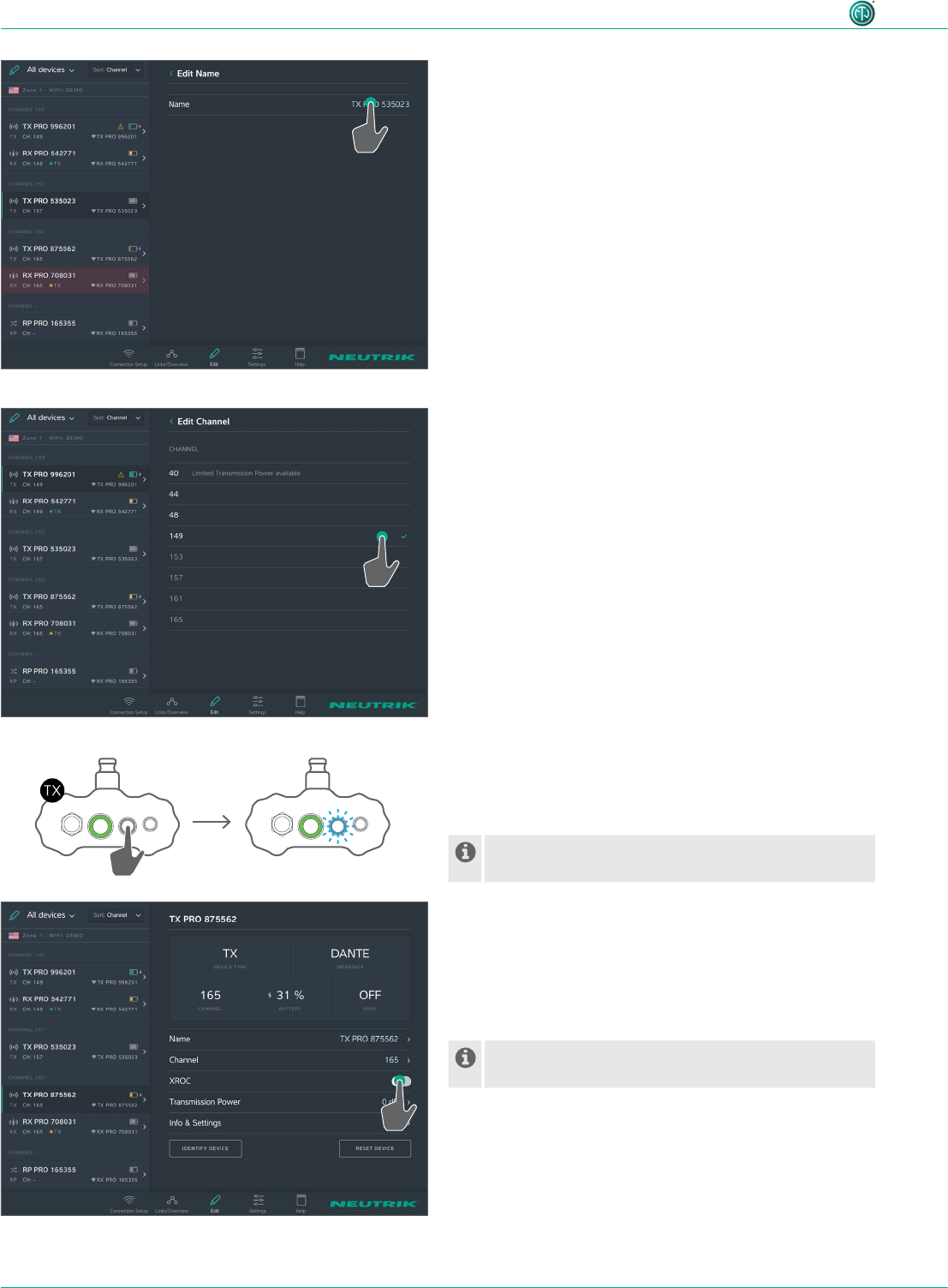
Changing device names
cOn the Edit page, tap the line Name.
cOn the Edit Name page, tap the device name.
(The entry keyboard appears.
cEnter the new name and conrm it.
cBack to the overview:
Tap Edit Name.
Changing the transmission channel
The transmission channel can only be set for one TX chan-
nel. Occupied or inactive channels cannot be selected and
are displayed in gray text. The active channel is marked
with ( .
cOn the Edit page, tap the line Channel.
cTap the desired channel number.
(The selected channel is marked with ( .
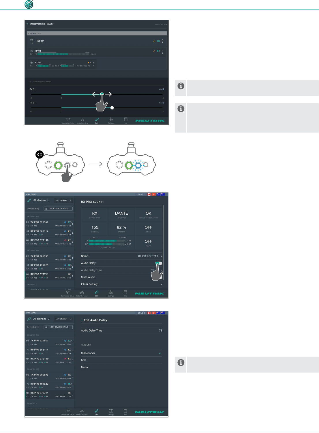
Activating/deactivating XROC mode
XROC mode can be activated or deactivated either on the
TX or via the app.
In XROC mode, only audio channel 1 is being
transmitted.
cActivating XROC mode via the device:
Press and hold the Link/XROC button for 4 seconds.
(The Link/XROC LED slowly ashes blue.
cActivating XROC mode via the app:
On the Edit page, tap the XROC ON/OFF button.
Whether XROC mode is active in the transmission
path is displayed in the device properties of an RX.
4 sec.
41User Manual – XIRIUM PRO® CA | BDA 471 2017/03
Operation
Setting transmission power
In the default setting, the transmission power is set to
0 dB.
cIf the devices are used indoors or over short distances:
Reduce the transmission power.
cIf the devices are used outdoors or over long distances:
Increase the transmission power.
If more than 1 TX are used in the network, set the
transmission power of all TXs to the same value.
Please consider chapter "4.4.3 Signal quality bar"
on page 24 and "4.4.4 Transmission power"
on page 25 for a proper setting of transmission
power.
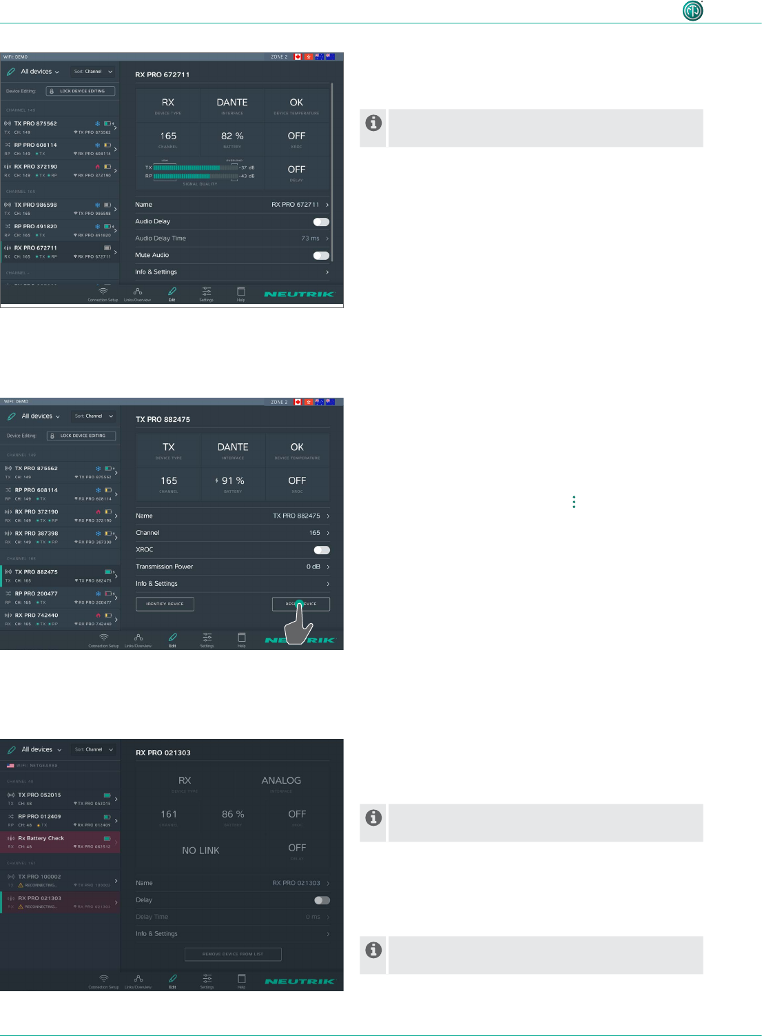
Activating/deactivating delay
cActivating the delay via the device:
Press and hold the Link/Delay button for 4 seconds.
(The Link/Delay LED slowly ashes blue.
4 sec.
cActivating the delay mode via the app:
On the Edit page, tap the Delay ON/OFF button.
Changing the delay time
^The delay function is active.
cOn the Edit page, tap the line Delay Time.
cOn the Edit Delay page, change the entered delay time.
cEnter and conrm the new delay time.
If the measurement unit is changed, the value is
automatically converted to the right unit.
42 User Manual – XIRIUM PRO® CA | BDA 471 2017/03
Operation
Mute audio signal
cOn the Edit page, tap the Mute Audio button.
A mute icon will be displayed in the Links /
Overview window next to the device.
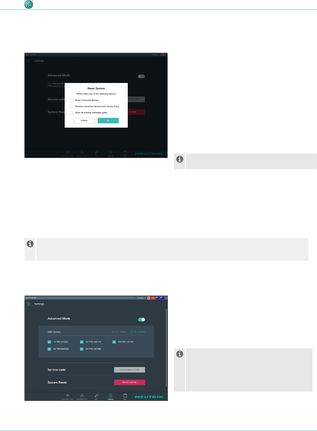
Resetting the device
Option 1:
cOn the Edit page, tap the Reset device button.
Option 2:
cOn the Links/Overview page, tap at the device.
cIn the options menu, tap Reset device.
The following settings are reset with this function:
•Resets the device name to the SSID name.
•Switches off XROC mode (TX).
•Switches off delay (RX).
•Resets the transmission power to the factory setting
(0 dB) (TX, RP).
•Makes the SSID public if it was hidden before (TX, RX)
•Turns off the RF attenuator (RX, Advanced Mode)
•Turns off the Audio Mute (RX)
Removing device from app display
If a device is out of the 2,4 GHz range, it can be temporarily
removed from the app display.
The Remove device from list button is only visible
when the device is unavailable to the app.
cRemove device from display:
Tap the Remove device from list button.
cConrm with OK in the Remove device window.
(The device is removed from the app display.
As soon as the device is available again, it is
displayed in the app.
43User Manual – XIRIUM PRO® CA | BDA 471 2017/03
Operation
5.7.2 Advanced Mode
The advanced mode is provided for RF specialists. Activating the Advanced mode will allow the user to edit an additional
parameter on each RX, called “RF attenuator”. The Advanced mode also allows to hide the SSIDs of the XIRIUM PRO
devices.
Activating / Deactivating the Advanced mode:
cOn the Settings Page, tap the Advanced Mode switch.
An activated attenuator or a hidden SSID is saved even after a Power Off/On of the device. The app detects
whether the attenuator is turned ON or the SSID is hidden and then automatically turns on the advanced
mode.
SSID visibility:
In high congested RF environment it is advisable to hide the SSIDs of all devices, in order that no requests will be received
by the XIRIUM PRO devices.
Change SSID visibility:
cTurn on Advanced Mode to enable the “SSID
visibility” parameter in the Settings menu.
cSingle devices or all devices at once can be set
hidden or visible.
cA checked box means the SSID is visible.
cAn unchecked box means that this SSID is hidden.
When hiding the SSID in Standalone Mode the
app will lose the device for a short time. While an
Android tablet will bring the device back in the
app automatically, iOS users may have to select
the device again in the Wi-Fi settings and then
return to the app..
During a change of the SSID visibility in network mode all other options are disabled until the process is nished com-
pletely.
The user can reset various options in the app.
The following options can be selected:
•Reset connected devices: All devices are reset to
the default setting.
•Remove connected devices from Access Point: All
devices are removed from the network.
•Show all warning messages again: All faded-out
warnings and notes are displayed again.
Reset System:
cOn the Settings page, tap the Reset system button.
cActivate option:
Tap the checkbox.
cConrm selection with OK.
(The app is reset.
If the XIRIUM PRO devices have been removed from
the accespoint a restart of the devices is necessary!
5.7 Editing system settings
5.7.1 Resetting the app
44 User Manual – XIRIUM PRO® CA | BDA 471 2017/03
Operation
RF attenuator:
RF attenuator is a parameter which can be set on each RX only if the Advanced Mode is turned on. It attenuates the RF
signal by 30 dB. The RF attenuator works best in combination with an increased transmission power on the TX. An acti-
vated RF attenuator increases the signal-to-noise ratio on that RX. Hence on an event with a lot of disturbing signals it is
possible to lower the surrounding noise and at the same time increase your transmission power of the TX to establish a
better reception.
Activating / Deactivating the RF attenuator:
cOn the Settings Page, tap the Advanced Mode switch to enable this additional parameter.
cOn the Edit Page, click on the RX and then tap the RF attenuator switch.
5.8 Setting up and mounting the XIRIUM PRO system
5.8.1 Positioning the devices
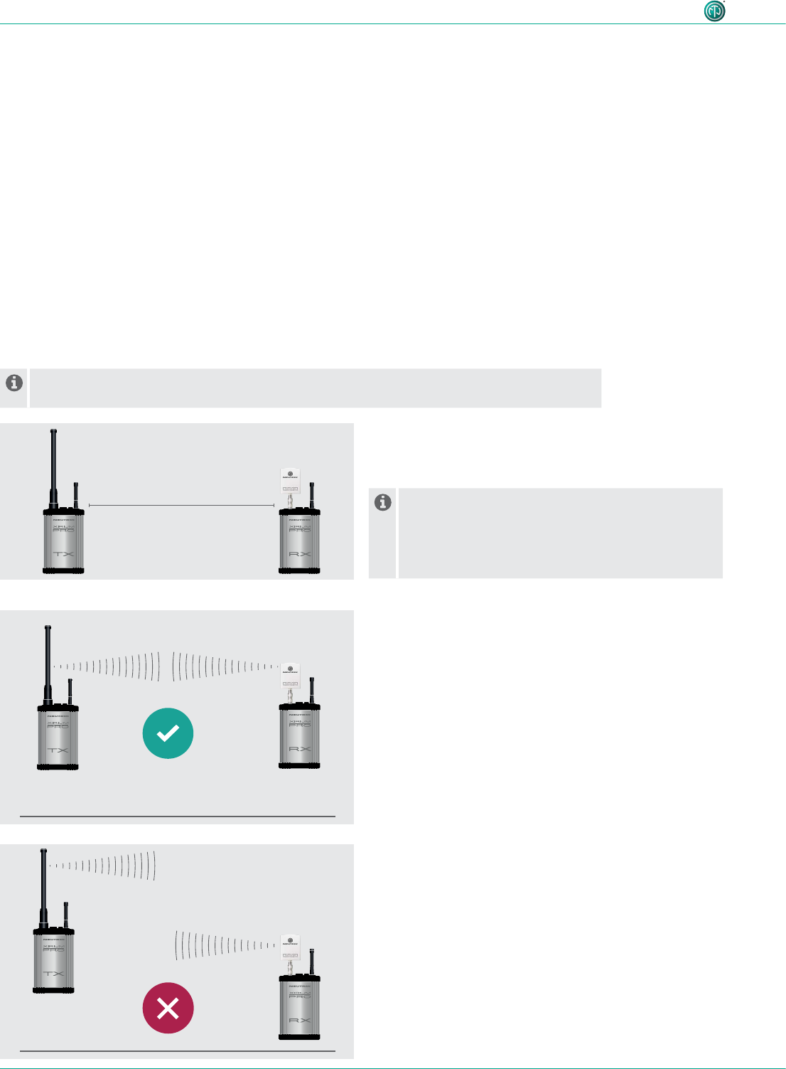
When positioning and setting the devices, observe the information in Section "4.4 Getting
started" on page 22.
cAlways keep a minimum distance of 10 feet between
the TX and each RX (with mounted 6 dBi antenna and
transmission power at -3 dB).
Under the following conditions, select a greater
minimum distance between TX and RX:
•XIRIUM PRO devices are operated with the 9 dBi
antenna.
•The transmission power is greater than -3 dB.
cAlways mount the devices so the device antennas are at
the same height.
min. 10 ft.
45User Manual – XIRIUM PRO® CA | BDA 471 2017/03
Operation
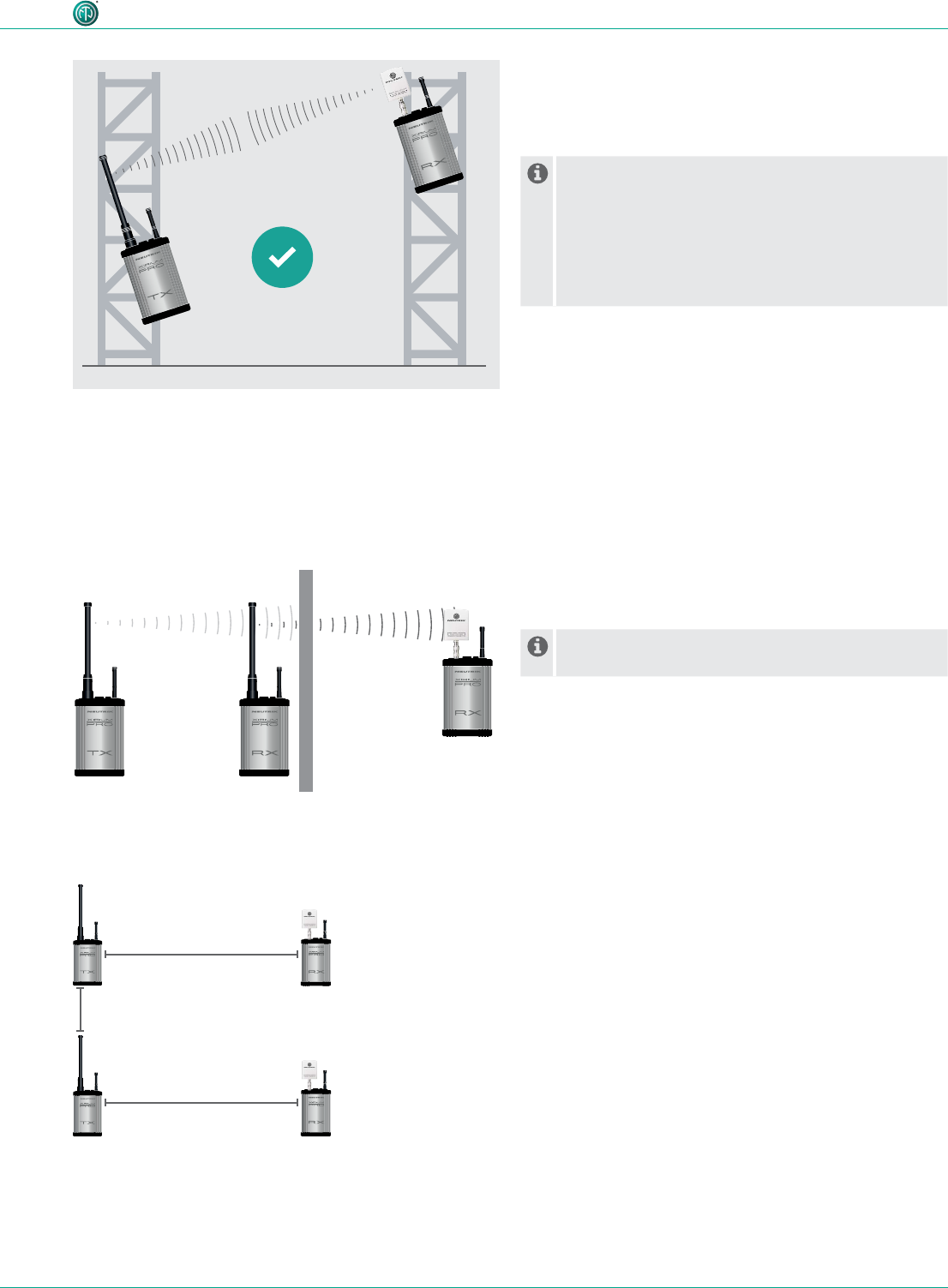
cPosition repeaters directly in front of obstacles.
(The signal will be transmitted through the obstacle.
Depending on the signal strength, the repeater can
also be positioned directly after the obstacle.
5.8.3 Systems with several transmitters
If several transmitters are used in the network, observe the following:
cSet the transmission power of all TXs to the same value.
cSelect the transmission channel for the TX in the app so at least one
channel is free between each channel used.
cWhen positioning the TX, maintain a minimum distance of at least 1 foot
between each TX.
cIncrease the recommended minimum distance between TX and RX to
164 feet.
cThe ideal RSSI level is between -60 to -50 dB.
cIf devices are not mounted at the same height:
Mount devices so they are parallel with each other.
An angled positioning is only allowed if the devices
are set to channel 149-165 or used indoors.
If the transmission needs to be done in the lower
channels (40-48) in an outdoor location a parallel
horizontal positioning of the devices with antennas
in a vertical position is necessary to comply with
FCC regulations.
5.8.2 Positioning the repeater
With the repeater, a connection can be stabilized by a redundant signal, obstacles can be
overcome, or the signal can be transmitted over twice the distance.
min. 1 ft.
min. 164 ft.
Repeater
min. 164 ft.

46 User Manual – XIRIUM PRO® CA | BDA 471 2017/03
Operation
5.8.4 Fastening and securing XIRIUM PRO devices
AES
RX
LIECHTENSTEIN
OUT
1 3 2
EBU
/
RX
LIECHTENSTEIN
LINE
OUT 1 (XROC) OUT 2
1 3 2 1 3 2
DANTE
C6
A
RX
LIECHTENSTEIN
OUT
C6
A
TX
LIECHTENSTEIN
IN
AES
1 2
3
EBU
/
PUSH
DANTE
C6
A
TX
LIECHTENSTEIN
IN
C6
A
REPEATER
RX
LIECHTENSTEIN
TX
LIECHTENSTEIN
IN 2
IN 1 (XROC)
LINE
1 2
3
PUSH
1 2
3
PUSH
100-240V~ 0.5A 50-60Hz
100-240V~ 0.5A 50-60Hz
100-240V~ 0.5A 50-60Hz100-240V~ 0.5A 50-60Hz100-240V~ 0.5A 50-60Hz
100-240V~ 0.5A 50-60Hz100-240V~ 0.5A 50-60Hz
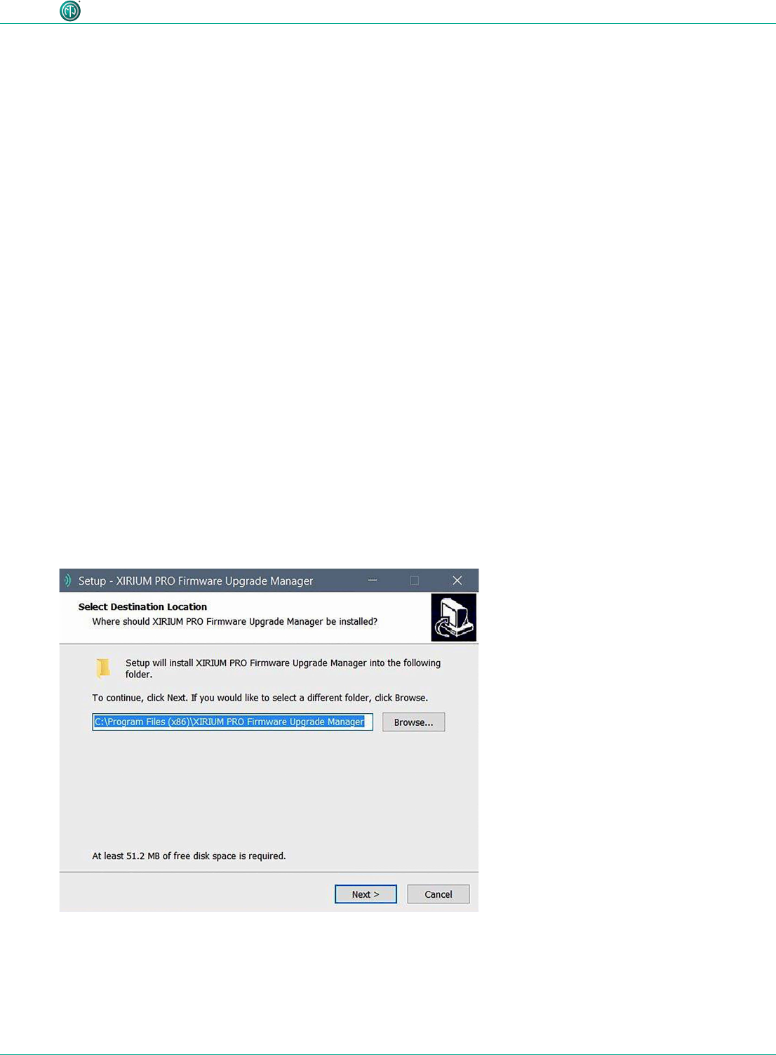
WARNING
Danger of falling due to incorrectly or incompletely fastened
devices!
cAlways mount and secure the devices according to the instructions.
cAlways mount the devices in an upright position.
cAlways mount the devices to the rig with the delivered ManfrottoTM
universal mounting clamp.
cAlso secure the devices with the arrestor cable (not included) to the safety
lug.
47User Manual – XIRIUM PRO® CA | BDA 471 2017/03
Operation
5.9 Upgrading firmware
The software "XIRIUM PRO Firmware Upgrade Manager" executes a rmware upgrade on the XIR-
IUM PRO base stations. The XIRIUM PRO USB data cable (NKXPRO-DATA), supplied with each base
station, is used for connection to a computer.
The software can be downloaded at no cost from the NEUTRIK website: www.neutrik.com
There’s an additional driver necessary, which can be downloaded from the Silicon Labs website
(https://www.silabs.com/products/mcu/Pages/USBtoUARTBridgeVCPDrivers.aspx). This driver is
required in order to detect the XIRIUM PRO device when connected to a computer.
5.9.1 Installing the XIRIUM PRO Firmware Upgrade Manager
System requirements
^PC with operating system Microsoft Windows XP, Windows 7, Windows 8, Windows 8.1 or
Windows 10.
PCs with ARM processors (Windows 8 and Windows 10) are not supported.
^Mac with Intel processor and OSX using version 10.8.5 or later.
Mac computers with PowerPC processors are not supported.
Download
cDownload ZIP le with the XIRIUM PRO Firmware Upgrade Manager Setup from the NEUTRIK
website and save it.
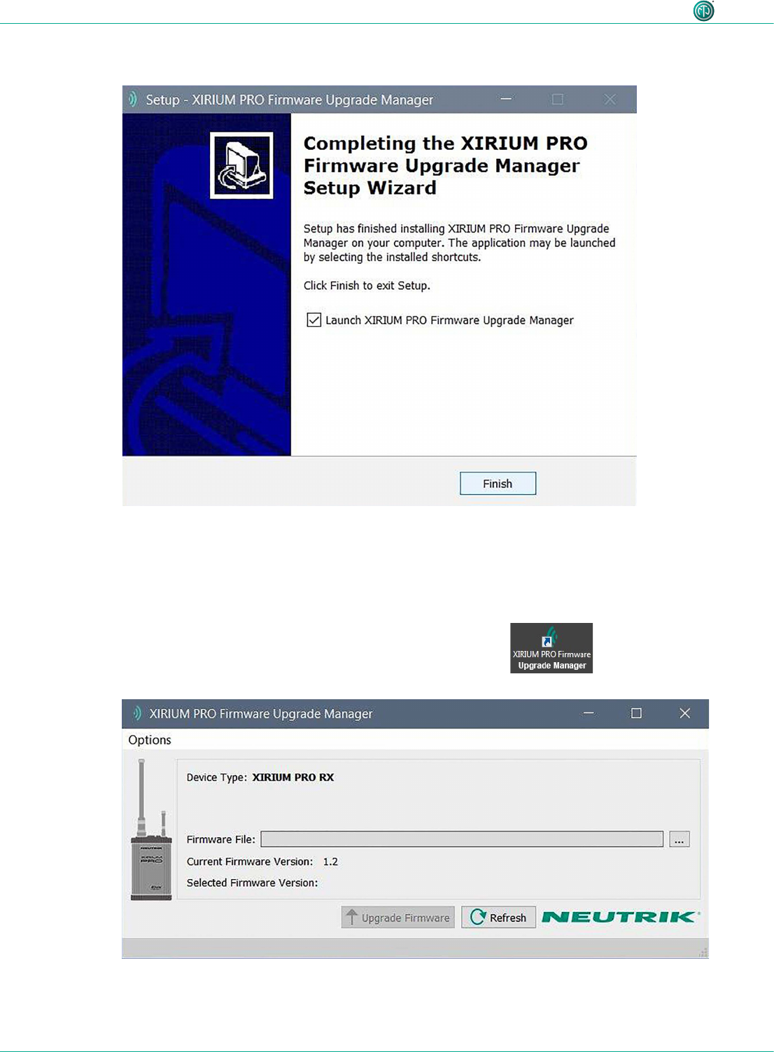
Installing the software
cDouble-click on the XIRIUM PRO Firmware Upgrade Manager application.
(The main window appears:
cSelect a location to install the software.
cClick the Next button.
48 User Manual – XIRIUM PRO® CA | BDA 471 2017/03
Operation
cFollow the subsequent installation steps.
5.9.2 Executing a firmware upgrade
cDownload the ZIP le with the current rmware from the NEUTRIK website and save it.
cStart the software:
Double-click the program icon on the Desktop.
cThe program window appears:
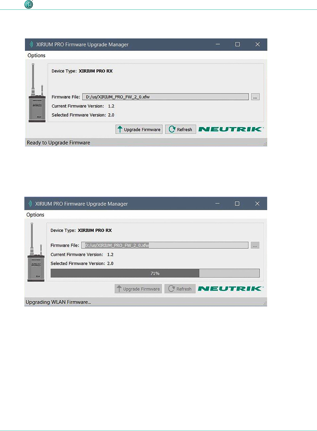
49User Manual – XIRIUM PRO® CA | BDA 471 2017/03
Operation
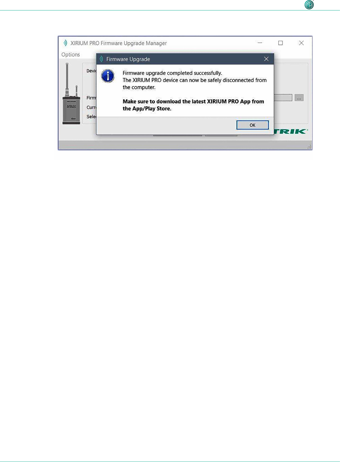
cConnect the XIRIUM PRO base station to the computer.
cClick the Refresh button to update all the displays.
cSelect the rmware le from the le selection eld Firmware File.
(The version number of the new rmware is displayed in Selected Firmware Version.
(Execute the upgrade:
Click the Upgrade Firmware button.
(The software automatically executes the upgrade.
50 User Manual – XIRIUM PRO® CA | BDA 471 2017/03
Operation
(As soon as the upgrade has completed, the software displays a message window.
cDisconnect the XIRIUM PRO base station from the computer.
5.9.3 Uninstalling the XIRIUM PRO Firmware Upgrade Manager
cUninstall the software through the add/remove function of the operating system.

51User Manual – XIRIUM PRO® CA | BDA 471 2017/03
Troubleshooting
6 Troubleshooting
Message Fault Cause Solution
Reconnecting… WLAN connection to
device not available.
Battery empty cConnect device to power
supply.
Device out of 2.4 GHz
network range.
cAvoid obstacles inuencing
reception.
cPosition device or access point
at a different location.
No Link! RX does not receive a
signal from TX.
TX battery empty cConnect device to power
supply.
Device out of 5 GHz
network range.
cAvoid obstacles inuencing
reception.
cPosition TX at a different
location.
cAdd repeater to transmission
path.
RSSI level “low” area RX repeater receives a
weak signal.
Distance between TX
and RX / repeater too
high.
cIncrease transmission power
on TX/repeater.
cDecrease distance between
TX and RX/repeater by a few
meters.
cIf no repeater in application:
Add repeater to transmission
path.
RSSI level “overload” area RX repeater receives a
signal that is too strong
Distance between TX
and RX/repeater too
low.
cDecrease transmission power
on TX/repeater.
cIncrease distance between
TX and RX/repeater by a few
meters.
Signal quality bar is orange
Signal quality bar is red
Packet loss is critical
Packet loss is too high
Some reections cause
a critical or high packet
loss at this position.
cPosition devices at a slightly
different location.
Access Point lost Connection between
tablet and access point
used is broken.
Tablet out of range of
access point.
cPosition device or access point
at a different location.
Flight mode active on
tablet.
cDeactivate ight mode on
tablet.
Access point changed Tablet connected with a
different access point.
Tablet out of range of
access point.
cPosition device or access point
at a different location.

52 User Manual – XIRIUM PRO® CA | BDA 471 2017/03
After operation
7 After operation
7.1 Dismounting devices
cDisconnect devices from audio sources/sinks.
cDisconnect devices from power supply and pull mains plug.
cDismount antennas.
cRemove modules from device.
7.2 Transporting
cAlways transport devices and accessories in the original packaging.
7.3 Storage
cIf devices are not used for a longer period:
Disconnect devices from power supply and pull mains plug.
cAlways store devices and accessories in the original packaging.
cAlways store devices in a clean, dry location.
cAlways protect devices from dirt, dust, heat, humidity and moisture.
7.4 Cleaning and care
DANGER
Danger of electric shock and property damage due to improper cleaning!
cDisconnect device from power supply before cleaning.
cNever immerse device or accessory in water under any circumstances.
cNever spray device or accessory with liquids under any circumstances.
cWipe the surfaces of the device and accessory with a soft cloth slightly moistened with a mild
soap solution.
cNever use aggressive, solvent-based or abrasive cleaning agents under any circumstances.
cNever use rough materials (e.g., cleaning cloths or sponges with a rough coating).
7.5 Maintenance and repair
The XIRIUM PRO devices do not contain any parts which can be maintained or repaired by the user.
cThese devices may only be repaired by a authorized XIRIUM PRO repair center.
cCheck devices regularly for visible damage to the housings, operation elements, connections,
cables and plugs.
cIf damage is detected, do not use devices under any circumstances
cImmediately disconnect devices from power supply.
cReplace defective cables or accessories immediately.

53User Manual – XIRIUM PRO® CA | BDA 471 2017/03
After operation
7.6 Disposal
cDispose of XIRIUM PRO devices and accessories in accordance with the applicable
local regulations.
cNever dispose of electrical devices or electrical accessories such as cables, plug,
batteries or components with household wastes under any circumstances.
cDispose of packaging and packaging elements in accordance with the applicable local
regulations.
cTake device components made of plastic, metal or other recyclables for reclamation in
accordance with the applicable local regulations.
54 User Manual – XIRIUM PRO® CA | BDA 471 2017/03
Appendix
8 Appendix
8.1 Integrating DANTE
8.1.1 Introduction to DANTETM
DANTETM stands for Digital Audio Network Through Ethernet and is an audio network protocol
developed by the Australian company Audinate. DANTETM delivers uncompressed, multichannel,
low-latency digital audio over a standard Ethernet network using Layer 3 IP packets. A TX DANTE
module is able to transmit up to two channels of digital audio, while the RX DANTE module can
receive two signals of a DANTETM network.
When XROC mode is enabled, only one channel is transmitted and received in a transmission
path, because the data rate is then lowered.
All products on which DANTETM is enabled work together to deliver perfectly synchronized audio.
This is managed through a single software application called “Dante Controller”.
Dante Controller is a free software application that enables routing audio and conguring devices
in a Dante network. Setting up a DANTETM network is very easy. Dante Controller offers automatic
device detection, one-click signal routing and user-editable device and channel labels.
A XIRIUM PRO device with an integrated DANTETM module can be connected to the DANTETM net-
work using common CAT5e or CAT6 cables. If a network switch is included in the system, it should
be at least a 1 Gbit network switch.
8.1.2 Enabling a DANTETM link
^Connect the computer to the DANTETM network with a standard CAT5e or CAT6 cable
^The DANTE Controller software is installed (https://www.audinate.com).
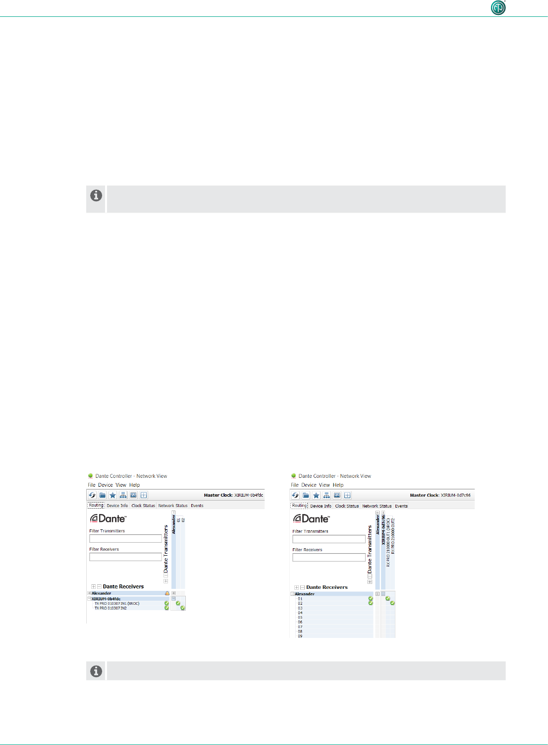
cRun the Dante Controller software.
cIn the routing menu, click on the + symbols of the devices.
cEstablish the desired link.
The XIRIUM PRO TX devices appear as DANTE receivers, and vice versa!

55User Manual – XIRIUM PRO® CA | BDA 471 2017/03
Appendix
8.2 Access point settings
Using an access point makes it possible to operate the app in network mode. This way, the entire
XIRIUM PRO system can be congured and monitored via the app.
8. 2 .1 Recommended settings
Any conventional access point can be used to set up a XIRIUM PRO network. Neutrik recommends
the following settings for the access point:
•For the strongest security option, use WPA2-AES as security protocol for authentication.
•If the access point has a dual-band radio, deactivate the 5 GHz band and only leave the 2.4 GHz
band activated.
•In the list of optional frequencies within the 2.4 GHz band, select channel 1 (2412 MHz),
channel 6 (2437 MHz), and channel 11 (2462 MHz) to ensure the channels do not overlap during
use.
•Make sure the http and https protocols are not blocked.

56 User Manual – XIRIUM PRO® CA | BDA 471 2017/03
Appendix
8.3 Technical specifications
General specifications
Radio frequency carrier range IEEE 802.11a, UNII-1 band from 5180 MHz to 5250 MHz (channels 36 – 48) and
UNII-3 band from 5725 MHz to 5825 MHz (channels 149 – 165), license-free
Data protocol Proprietary (DiWA technology)
Transmit power UNII-1 band: conducted 13 dBm / 19 dBm EIRP (with 6 dBi antenna) /
22 dBm EIRP (with 9 dBi antenna), FCC compliant
UNII-3 band: conducted 26 dBm / 32 dBm EIRP (with 6 dBi antenna) /
35 dBm EIRP (with 9 dBi antenna), FCC compliant
Range Up to 1000 m point to point (LOS)*, longer range depending on obstacles,
reexions, interferences, XROC mode
Audio performance (analog to analog per wireless link)
THD + Noise (TX Gain = min.) < 0.01 % @ 20 Hz – 10 kHz, 4 dBu
Frequency response ± 0.3 dB @ 20 Hz – 20 kHz ref. 1 kHz
Dynamic range > 105 dB @ 1 kHz, A-weighted
> 105 dB @ 1 kHz, A-weighted < -80 dB @ 20 kHz
Number of audio channels
@ 24 Mbps
2
Number of audio channels
@ 6 Mbps
1 (XROC mode)
Number of receivers (RX only) Unlimited number of RX clients
Converter resolution (ADC & DAC) 24 bit
Sampling rate 48 kHz
Latency (Delay) 3.6 ms (analog to analog)
Transmission method Compression-free, no reduction of converted data
Operating temperature 32 °F to +122 °F / 0 °C to +50 °C
Storage temperature -4 °F to +176 °F / -20 °C to +80 °C
Additional digital audio interfaces
AES/EBU 24 bit / 48 kHz according to AES3-2003
Dante AoE (Audio over Ethernet) Proprietary protocol by Audinate®
* valid for a transmission in the UNII-3 band

57User Manual – XIRIUM PRO® CA | BDA 471 2017/03
Appendix
TX specific characteristics
Antenna 5-6 GHz – Audio
transmission
Omni-directional, 6 dBi, 25° Elevation and 360° Azimuth, N-connector male
(direct mount)
Antenna 2.4 GHz – Control data
transmission
1/2 wave dipole with SMA female connectors
Number of audio channels @ 24 bps 2
Number of audio channels
@ 6 Mbps
1 (XROC mode)
Analog input specs
Input mode Input level
Input Imp.
kOhm
Rated Source
Imp. Ohm
max.* dBu Connector type
Line (balanced) 10 1000 22 XLR
Indicators LEDs: Power ON / Start up / Low battery status / XROC mode / Linking process /
Audio transmission
Controls Power ON / Linking process / XROC mode
Power supply Mains input over powerCON TRUE1 (100-240 VAC 50/60 Hz) or internal
battery **
Dimensions (w x h x d) 5.6 x 2.5 x 9.7 in / 142 x 64 x 247 mm (without antennas)
Weight 1.59 lbs / 0.72 kg
Optional accessories Module Interfaces (Analog, Digital, Dante), mounting clamp
* maximum input level before signal overow, 0 dBu = 0.775 V rms
** typical battery runtime 10 hours, depending on type of module, transmission power settings,
XROC mode, number of charging cycles and operating temperature

58 User Manual – XIRIUM PRO® CA | BDA 471 2017/03
Appendix
RX SPECIFIC CHARACTERISTICS
Antenna 5-6 GHz - Audio
Transmission
Omni-directional, 6 dBi, 25° Elevation and 360° Azimuth, N-connector male
(direct mount)
Antenna 2.4 GHz - Control Data
Transmission
1/2 wave dipole with SMA female connectors
Number of audio channels 2
Analog output specs
Output Type Output Level
Output Imp.
Ohm
Rated Load
Imp. kOhm
Nominal*
dBu
Max. Level
dBu
Connector
type
Line (balanced) < 800 10 022 XLR
Indicators LEDs: Power ON / Start up / Low battery status / Audio delay / Linking process /
Audio reception
Controls Power ON / Linking process / Audio delay
Power Supply Mains input over powerCON TRUE1 (100-240 VAC 50/60 Hz) or internal
battery **
Dimensions (w x h x d) 5.6 x 2.5 x 9.7 in / 142 x 64 x 247 mm (without antennas)
Weight 1.59 lbs / 0.72 kg
Optional Accessories Module Interfaces (Analog, Digital, Dante, Repeater), mounting clamp
* if TX source = 0dBu
** typical battery runtime 10 hours, depending on type of module, transmission power settings,
XROC mode, number of charging cycles and operating temperature
Antennas– Omni-directional antenna / Frequency band: 5.150 GHz - 5.875 GHz
Type NXPA-6-360-25 NXPA-9-360-12.5
Gain 6 dBi 9 dBi
Beam width horizontal 360° 360°
Beam width vertical 25° 12.5°
Connector N-connector male N-connector male
Dimensions 10.63 in / 270 mm 14.57 in / 370 mm
Weight 0.75 lbs / 0.34 kg 0.75 lbs / 0.34 kg
Operating temperature 32 °F to +122 °F / 0 °C to +50 °C 32 °F to +122 °F / 0 °C to +50 °C

59User Manual – XIRIUM PRO® CA | BDA 471 2017/03
Appendix

www.neutrik.com / www.xirium.net
BDA 471 - XIRIUM PRO CA, AUS, NZ / 2017-03 - Data subject to change without prior notice. © 2017 NEUTRIK® . NEUTRIK®, XIRIUM® are registered trademarks of NEUTRIK AG. ALL RIGHTS RESERVED.
Liechtenstein (Headquarters)
NEUTRIK AG, Im alten Riet 143, 9494 Schaan
T +423 237 24 24, F +423 232 53 93, neutrik@neutrik.com
Germany / Netherlands / Denmark / Austria
Neutrik Vertriebs GmbH, Felix-Wankel-Strasse 1, 85221 Dachau, Germany
T +49 8131 28 08 90, info@neutrik.de
Great Britain
Neutrik (UK) Ltd., Westridge Business Park, Cothey Way
Ryde, Isle of Wight PO33 1 QT
T +44 1983 811 441, sales@neutrik.co.uk
France
Neutrik France SARL, Rue du Parchamp 13, 92100 Boulogne-Billancourt
T +33 1 41 31 67 50, info@neutrik.fr
USA
Neutrik USA Inc., 4115 Taggart Creek Road, Charlotte, North Carolina, 28208
T +1 704 972 30 50, info@neutrikusa.com
Japan
Neutrik Limited, Yusen-Higashinihonbashi-Ekimae Bldg., 3-7-19
Higashinihonbashi, Chuo-ku, Tokyo 103
T +81 3 3663 47 33, mail@neutrik.co.jp
Hong Kong
Neutrik Hong Kong LTD., Suite 18, 7th Floor Shatin Galleria
Fotan, Shatin
T +852 2687 6055, neutrik@neutrik.com.hk
China
Ningbo Neutrik Trading Co., Ltd., Shiqi Street, Yinxian Road West
Fengjia Villiage, Yinzhou Area, Ningbo, Zhejiang, 315153
T +86 574 88250488 800, neutrik@neutrik.com.cn
India
Neutrik India Pvt. Ltd., Level 3, Neo Vikram, New Link Road,
Above Audi Show Room, Andheri West, Mumbai, 400053
T +91 982 05 43 424, anklesaria@neutrik.com
Associated companies
Contrik AG
Steinackerstrasse 35, 8902 Urdorf, Switzerland
T +41 44 736 50 10, contrik@contrik.ch
H. Adam GmbH
Felix-Wankel-Straße 1, 85221 Dachau, Germany
T +49 08131 28 08-0, info@adam-gmbh.de