Nevro IPG2000 Implantable Spinal Cord Stimulator User Manual Users manual
Nevro Corporation Implantable Spinal Cord Stimulator Users manual
Nevro >
Users manual
Physician Implant
Manual
Senza®
Senza II™
ONLY
DRAFT

Physician Implant Manual 11051 Rev D. DRAFT 2
NEVRO CORP.
All questions or concerns about Nevro Corp. products should be forwarded to:
Nevro Corp.
1800 Bridge Parkway
Redwood City, CA 94065, USA
Tel: +1.650.251.0005
Fax: +1.650.251.9415
info@nevro.com
MDSS GMBH
Schiffgraben 41
D-30175 Hannover,
Germany
Australian Sponsor
Emergo Asia Pacific Pty Ltd
201 Sussex Street, Darling Park, Tower II, Level 20
Sydney, NSW 2000
Australia
© Copyright 2017, Nevro Corp. All rights reserved.
No part of this publication may be reproduced, transmitted, transcribed, stored in a retrieval system or translated into
any language or computer language, in any form or by any means, including, but not limited to, electronic, magnetic,
optical, chemical, manual, or otherwise without written permission of Nevro Corp.
Registered Trademarks: Nevro, Senza, Senza II, HF10, and the Nevro Logo are trademarks of the Nevro Corp.
IMPORTANT: Do not change or modify any component of the Senza or Senza II Spinal Cord Stimulation system, unless
expressly approved by Nevro Corp.
CAUTION: Federal law restricts this device to sale, distribution and use by or on the order of a physician.
Physician Implant Manual 11051 Rev D. DRAFT 3
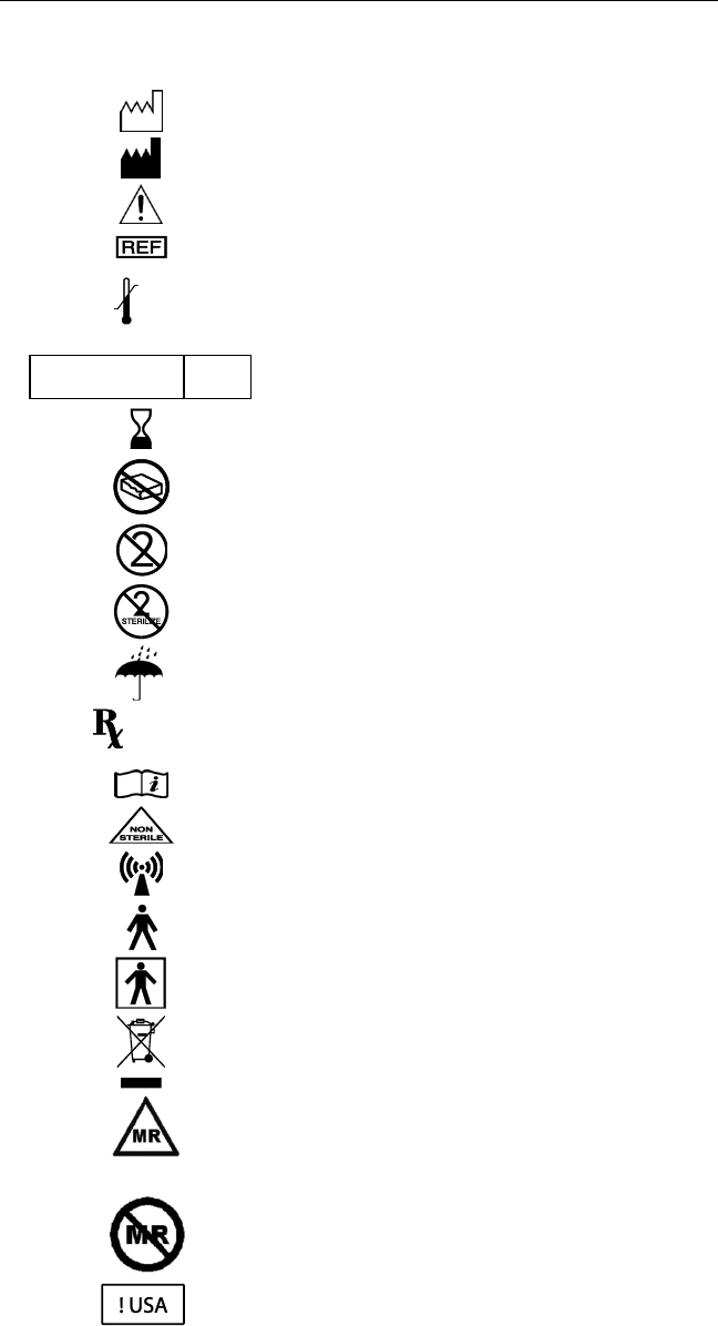
Explanation of symbols. Refer to the product for symbols that apply.
Symbols
Description
SN
Serial number
LOT
Batch code
Date of Manufacture
Manufacturer
Caution
Catalog number
Temperature limitation (storage)
Sterilized using ethylene oxide
Use by
Do not use if package is damaged
Do not reuse
Do not re-sterilize
Keep dry
Prescription only
Consult Instructions for Use
Non-sterile
Non-ionizing radiation
Type B Applied Part
Type BF Applied Part
Do not dispose of this product in the unsorted
municipal waste stream. Dispose of this product
according to local regulations.
Conditional
MR Conditional
MR unsafe
For USA audiences only
XX C
XXX F
XX C
XX F
STERILE
EO
ONLY
Physician Implant Manual 11051 Rev D. DRAFT 4
Table of Contents
Device Description ............................................................................................................................. 5
Indications for Use ............................................................................................................................. 7
Contraindications ............................................................................................................................... 7
Warnings ........................................................................................................................................... 7
Precautions...................................................................................................................................... 11
Adverse Effects ................................................................................................................................ 14
a. System Specifications .......................................................................................................................... 16
b. Charger Specifications ......................................................................................................................... 16
c. Stimulation Parameter Ranges ............................................................................................................ 16
d. Quality of Wireless Service ................................................................................................................. 16
e. Wireless Security ................................................................................................................................. 16
f. Telemetry Information ......................................................................................................................... 17
g. Wireless Charging Information ........................................................................................................... 17
h. Electromagnetic Interference ............................................................................................................. 17
Patient Identification ....................................................................................................................... 20
Instructions for Use .......................................................................................................................... 21
Guidelines for Trial-phase Implantation ............................................................................................ 21
a. Temporary vs. Permanent Trials ..................................................................................................... 21
b. Pre-op Instructions .......................................................................................................................... 21
c. Lead Placement ............................................................................................................................... 22
d. Performing Intra-operative Testing ................................................................................................ 23
e. Preparing for Temporary Trial......................................................................................................... 24
f. Anchoring the Lead ......................................................................................................................... 24
g. Connecting an Extension to the Lead ............................................................................................. 25
h. Percutaneous Tunneling of the Extension ...................................................................................... 25
i. Closing the Incision Sites ................................................................................................................. 26
j. Connecting the Lead or Extension to the Trial Stimulator .............................................................. 26
Guidelines for Permanent Implantation ............................................................................................ 26
a. Pre-op instructions .......................................................................................................................... 26
b. If the patient was given a temporary trial ...................................................................................... 26
c. If the patient was given a Permanent trial...................................................................................... 27
d. IPG Implantation ............................................................................................................................. 28
e. IPG Explant or Replacement ........................................................................................................... 30
Device Information for the Clinical Staff ........................................................................................... 30
a. Trial Stimulator .................................................................................................................................... 30
b. Rechargeable IPG ................................................................................................................................ 30

Physician Implant Manual 11051 Rev D. DRAFT 5
1. Device Description
The Senza® and Senza II™ Spinal Cord Stimulation (SCS) Systems are neuromodulation devices designed to
deliver electrical stimulation for the treatment of chronic intractable pain of the trunk and/or limbs.
The Senza and Senza II Systems are implantable systems and deliver stimulation using implantable leads
and a rechargeable, implantable pulse generator (IPG). The IPG is implanted in a subcutaneous pocket
and is capable of stimulating the spinal cord nerves when used with one or more leads. The IPG is
controlled by a Patient Remote and/or the Clinician Programmer. Other components of the Senza and
Senza II Systems include an external Trial Stimulator capable of delivering the same stimulation as the
IPG, Lead Extensions, Adaptors, Charger and charging system, operating room (OR) cables and surgical
accessories. Details regarding the Senza and Senza II Systems are as follows:
Senza System Details – Major Components
• Implantable Pulse Generator (Models Senza and Senza II): The Implantable Pulse Generator
(IPG) is a rechargeable implantable device with 16 output channels capable of stimulating the
spinal cord nerves through electrode leads. The IPG is designed to produce current-regulated,
charge-balanced, biphasic, capacitively-coupled, rectangular output pulses. The IPG header
contains the charging coil and two ports to allow the insertion of leads. The rechargeable
battery is contained in a hermetically sealed housing, which is inside the hermetic IPG Titanium
enclosure.
• Trial Stimulator: The Trial Stimulator is a battery-powered, handheld device capable of
providing the same stimulation as the IPG. During the Trial Phase of SCS, the subject wears this
external Trial Stimulator for a period of time to evaluate the effectiveness of the stimulation
prior to receiving a permanent implant. The Trial Stimulator is connected to the subject’s
implanted leads by the use of OR cables.
• IPG or Trial Stimulator interface with other Senza components: The Charger transmits energy
transcutaneously to recharge the IPG battery. The IPG and Trial Stimulator communicate with
the Patient Remote or Clinician Programmer via the Programmer Wand. Patients are also able
to send commands to the IPG or Trial Stimulator directly using the Patient Remote. The IPG also
includes a magnetic switch for turning the therapy off by using an external magnet.
• Patient Remote: The Patient Remote is a handheld battery operated unit able to communicate
with the IPG or Trial Stimulator. The Patient Remote includes multiple controls and indicators
for the purpose communicating with these components.
• Charger: This Charger is used by the subject to transcutaneously charge the IPG battery. It is a
portable device powered by a rechargeable battery and can be held in one hand.
• Programmer: The Clinician Programmer programs the IPG or Trial Stimulator via the
Programmer Wand via a graphical user interface (GUI).
• Programmer Wand: The Programmer Wand is the Clinician Programmer interface that allows
the communication with the IPG or Trial Stimulator.
• Leads, Lead Extensions and Lead Adaptors: There are two types of leads: Percutaneous and
Surgical. The Nevro Leads are intended to be used with an IPG or Trial Stimulator for use in
delivering stimulation. The Leads are for single use and interface with the IPG, Lead Extensions,
OR Cable, and lead accessories.
Physician Implant Manual 11051 Rev D. DRAFT 6
The Percutaneous Lead has an isodiametric body made out of Pellethane 55D, which carries
eight low impedance cables. The proximal connector end has eight (8) individual contacts which
interface with the Nevro IPG and Lead Extensions.
The proximal end of the Surgical Lead has two legs each with 8 contacts. The proximal end of the
Surgical Lead is identical to the proximal end of the Percutaneous Lead. The distal end of the
lead is molded out of Silicone material and has 16 distal electrodes.
The proximal end of the Lead Extension is identical to the proximal ends of the Percutaneous
and Surgical Leads. The distal end of the Lead Extension is designed to accept the proximal end
of the Percutaneous or Surgical Lead. The construction of the Lead Extension is identical along
its length to the Percutaneous Lead.
The M8 and S8 Lead Adaptors allow a physician to connect a specific implanted Medtronic or St.
Jude Medical lead, respectively, with the Nevro Lead Extension or IPG. The construction of the
Lead Adaptors is identical to the Lead Extension.
Senza System Details - Surgical Accessories
• Torque Wrench: The Torque Wrench is used to tighten the setscrews that lock the Lead into the
IPG, to lock the Lead into a Lead Extension/Adaptors, or to activate the retention mechanism on
the Active Anchors.
• Lead anchors: The Lead Anchors are used to anchor the Lead to the fascia or supraspinous
ligament.
• Insertion Needle: The Insertion Needle is used during implant surgery to introduce the
Percutaneous Lead between the vertebrae into the epidural space.
• Coiled Lead Blank: The Coiled Lead Blank is optionally used during surgery to clear a path for
the introduction of the Percutaneous Lead into the epidural space.
• Stylets: The Stylets are used to maneuver the Lead through the epidural space to the desired
implant location.
• IPG Port Plug: The IPG Port Plug is provided to seal the port of the IPG that is not in use when
only one Lead is implanted.
• OR Cables: The Operating Room (OR) Cables make electrical and mechanical connections
between the Trial Stimulator and the Leads or Lead Extensions.
• Tunneling Tool: The Tunneling Tool creates a subcutaneous tunnel for the leads from the IPG
site to the midline incision.
• IPG Template: The IPG Template acts as an optional aid for physicians in proper sizing of the IPG
implant pocket.
• Mx Trial Adaptor: The Mx Trial Adaptor is intended to connect a Medtronic OR cable to the
Nevro Trial Stimulator.
Physician Implant Manual 11051 Rev D. DRAFT 7
2. Indications for Use
The Senza® and Senza II™ neuromodulation systems are indicated as aids in the management of chronic
intractable pain of the trunk and/or limbs, including unilateral or bilateral pain associated with the following:
failed back surgery syndrome, intractable low back pain, and leg pain.
3. Contraindications
The Senza and Senza II systems should not be used for those patients who:
• Are poor surgical candidates.
• Fail to receive effective pain relief during trial stimulation.
• Are unable to operate the SCS system.
4. Warnings
Stimulation Frequencies - Stimulation frequencies in the range of 2 Hz to 1,200 Hz are indicated for
paresthesia-based therapy and the system must be configured to produce paresthesia. Stimulation at
10,000 Hz is indicated as paresthesia-free therapy and the system must be configured to deliver paresthesia-
free stimulation. Stimulation between 1,200 Hz and 10,000 Hz has not been evaluated for safety,
effectiveness and perception of paresthesia. Specifically, for stimulation frequencies above 1,200 Hz,
amplitudes that produce paresthesias have not been evaluated and therefore it is unknown whether injury
may occur.
Stimulation at vertebral levels above T8 – The safety of program settings above 1,200 Hz have not been
studied above the T8 vertebral level.
Pediatric Use – The safety and effectiveness of spinal cord stimulation has not been established for pediatric
use.
Other Active Implanted Devices – The Senza and Senza II systems may interfere with other implanted
stimulators, such as cardiac pacemakers and defibrillators which have sensing features, and may result in
sensing problems or inappropriate responses. The effect of other implanted devices, including deep brain
stimulators, peripheral nerve stimulators, implanted drug delivery pumps, and cochlear implants on the Senza
and Senza II systems are unknown.
Sleep – Patients using therapy that generates paresthesia (tingling sensations caused by stimulation) may
choose to turn stimulation off to avoid uncomfortable sensations during sleep (see Warning regarding
Stimulation Frequency). Therapy at 10 kHz does not generate paresthesia and therefore stimulation can
remain on during sleep.
Operation of Vehicles (e.g., driving) or Machinery – Patients using therapy that generates paresthesia (see
Warning regarding Stimulation Frequencies) should not operate motorized vehicles such as automobiles or
potentially dangerous machinery and equipment with the stimulation on. Stimulation must be turned off first
in such cases. For these patients, any sudden stimulation changes may distract patients from proper operation
of the vehicle, machinery, or equipment.

Physician Implant Manual 11051 Rev D. DRAFT 8
Therapy at 10 kHz does not generate paresthesia and it is less likely that sudden stimulation changes resulting
in distraction could occur while having stimulation on when operating moving vehicles, machinery, and
equipment.
Heat From Charging – The charging coil may become warm while charging. Patients may experience
discomfort or burn if they charge while sleeping or do not use the provided charging belt. Additionally, the
charger should not be placed over insensate skin.
Diathermy Therapy – Do not use shortwave diathermy, microwave diathermy or therapeutic ultrasound
diathermy on patients implanted with a neuromodulation system. Energy from diathermy can be transferred
through the implanted system and can cause tissue damage at the location of the implanted electrodes,
resulting in severe injury or death. The neuromodulation system, whether it is turned on or off, may be
damaged.
Computed Tomography (CT) – Before beginning a CT scan, the operator should use CT scout views to
determine if implanted or externally worn electronic medical devices are present and if so, their location
relative to the programmed scan range.
For CT procedures in which the medical device is in or immediately adjacent to the programmed scan range,
the operator should:
• Determine the device type;
• If practical, try to move external devices out of the scan range;
• Ask patients with neurostimulators to shut off the device temporarily while the scan is performed;
• Minimize x-ray exposure to the implanted or externally worn electronic medical device by:
o Using the lowest possible x-ray tube current consistent with obtaining the required image
quality; and
o Making sure that the x-ray beam does not dwell over the device for more than a few seconds;
Important note: For CT procedures that require scanning over the medical device continuously for more than a
few seconds, as with CT perfusion or interventional exams, attending staff should be ready to take emergency
measures to treat adverse reactions if they occur.
After CT scanning directly over the implanted or externally worn electronic medical device:
• Have the patient turn the device back on if it had been turned off prior to scanning.
• Have the patient check the device for proper functioning, even if the device was turned off.
• Advise patients to contact their healthcare provider as soon as possible if they suspect their device
is not functioning properly after a CT scan.
Magnetic Resonance Imaging (MRI) – The Senza and Senza II systems are MR Conditional which means that
safety has been demonstrated only within specifically defined conditions. Scanning under different conditions
may result in severe patient injury or device malfunction. Refer to the Senza system 1.5T and 3T MRI
Guidelines (US) manual for MRI-specific warnings and precautions on conducting a MRI scan on a patient with
the Senza or Senza II systems.
Devices in Hospital/Medical Environments – The use of following medical devices or procedures may damage
the SCS system or turn the stimulation off. After usage of these devices or procedures, the IPG may need to be
explanted as a result of permanent damage.

Physician Implant Manual 11051 Rev D. DRAFT 9
• Electrocautery: The IPG should not be exposed to electrocautery. If electrocautery is necessary with the
IPG implanted, use bipolar electrocautery. Do not use monopolar electrocautery.
• External defibrillation: The safety of discharge of an external defibrillator on patients implanted with an
SCS system has not been established.
• Lithotripsy or high-output ultrasonics: Do not use these devices in patients with an implanted IPG.
• Radiation therapy: If radiation therapy is needed near the IPG, shield the area over the IPG.
• Ultrasonic scanning: Do not use it over the IPG.
If a patient is required to undergo lithotripsy, high-output ultrasound, electrocautery, external defibrillation,
radiation therapy, or ultrasonic scanning, follow these precautions.
• Turn off the IPG before the procedure.
• Use the equipment as far away from the IPG as possible.
• Keep fields, such as current, radiation, or high-output ultrasonic beams, away from the IPG.
• Equipment should be set to the lowest energy setting possible.
• After the therapy or procedure, check to see that the IPG is functioning properly by gradually increasing
the IPG’s stimulation to the desired level.
• If the patient suspects that the device is not functioning properly after the use of these therapies or
procedures, advise the patient to contact his or her healthcare provider.
Electromagnetic Interference (EMI) – Electromagnetic energy is generated by equipment found in the home,
work, medical or public environments. Electromagnetic interference may occur when the energy is strong
enough to interfere with neurostimulator function. Most electrical devices and magnets that patients will
encounter in a normal day are unlikely to affect the operation of the SCS system. However, some equipment
may generate strong electromagnetic fields that can turn the stimulator (IPG or TSM) off or cause shocks or
jolts (see below). Patients should keep away from areas of EMI and turn off the stimulator if they are in such
an area. The following are examples of sources that can potentially generate strong EMI.
• Theft detectors or security screeners such as airport security screening devices, retail store, and
libraries.
Note: It is recommended that patients request assistance to bypass the theft detector or
security screener. If they must go through a screening device, the patient should turn off
the stimulator and go through the area as quickly as possible and as far away from the
theft detector or security screener as possible.
• Power lines and power generators
• Arc welders
• Large, magnetized stereo speakers
• Radio frequency identification devices (RFID)
If EMI is suspected or encountered, patients will need to turn off the stimulator. Then, the patients will need
to move away from the EMI area and check whether the therapy is on or off. Before therapy can be turned off,
the batteries may need to be replaced in the TSM or recharged in the IPG.
Strong electromagnetic interference can result in the following:
• Serious patient injury, resulting from heating of the implanted components of the neurostimulation
system and damage to surrounding tissue.

Physician Implant Manual 11051 Rev D. DRAFT 10
• System damage, resulting in a loss of or change in symptom control and requiring surgical
replacement.
• Operational changes to the neurostimulator, causing it to turn on or off
• Unexpected changes in stimulation, causing a momentary increase in stimulation or intermittent
stimulation, which some patients have described as a jolting or shocking sensation. Although the
unexpected change in stimulation may feel uncomfortable, it does not damage the device or injure the
patient directly. In rare cases, as a result of the unexpected change in stimulation, patients have fallen
down and been injured.
Strong electromagnetic fields arising from closeness to electrical equipment such as mobile phones, satellite
phones and radio systems may interfere with the radio communication between the Remote Control and IPG.
As described in the “Troubleshooting” section of this manual, communication failure is indicated by three
beeps. Communication can be restored by moving away from the interfering electrical equipment and retrying
the operation.
Electrostatic Discharge (ESD) is a common source of electromagnetic interference that can occur when a
person or object accumulates a static charge. ESD is made worse by low humidity and synthetic materials.
• If the battery terminals of the Trial Simulator are exposed to ESD, the device may reset and stop
stimulation. Stimulation can be restarted by following the instructions in the “How to Turn ON
Stimulation” section of the Patient Manual. To avoid unintentionally stopping stimulation, do not open
the battery compartment while stimulation is ongoing.
• ESD may cause the Charger to stop charging the IPG. If this happens, charging can be resumed by
repeating the steps in the “How to Charge the IPG” section of this manual. ESD events can be
minimized by keeping the charger in the Charger Holster while recharging the IPG.
Radio-frequency or microwave ablation – Safety has not been established for radiofrequency (RF) or
microwave ablation in patients who have an implanted neurostimulation system. Induced electrical currents
may cause heating, especially at the lead electrode site, resulting in tissue damage.

Physician Implant Manual 11051 Rev D. DRAFT 11
5. Precautions
Patients Who Are Poor Surgical Candidates – Do not implant an SCS system if a patient is considered a poor
surgical candidate. Implanting an SCS system has risks similar to surgical procedures of the spine, including
spinal fluid leak, headaches, swelling, bruising, bleeding, infection, or paralysis.
Pregnancy – The safety and effectiveness of spinal cord stimulation has not been established for use during
pregnancy or nursing.
Patient Activities – Patients using therapy that generates paresthesia (see Warning regarding Stimulation
Frequencies) may experience increased paresthesia when changing posture or making abrupt movements.
Such patients should lower the amplitude or turn off the stimulation before making posture changes, such as
stretching and moving their arms over their head. If unpleasant sensations occur, the IPG should be turned off.
Stimulation at 10 kHz does not generate paresthesia, so patients should not experience unpleasant sensations
caused by posture changes or movement. As such, patients would not need to change amplitudes in their
programs in response to posture changes or movement.
Patient Activities Related to Lead Movement – Advise patients to not make sudden and excessive bending,
stretching, or twisting movements, particularly within the first weeks after the surgery. An implanted lead can
move from its original location during such movements, which might affect delivery of therapy. In such cases,
the patient may need to be reprogrammed or the lead may need to be repositioned through another
operation.
Scuba Diving and Hyperbaric Chambers – Patients should avoid scuba diving to depths greater than 35 meters
and hyperbaric chambers with pressure greater than 4.5 ATM. Pressure greater than 35 meters or 4.5 ATM
may damage the Senza and Senza II systems.
Storage – Store the system components and accessories between the prescribed temperatures. Excessively
hot or cold temperatures may damage the components, particularly high heat. Devices should be kept in
temperature regulated areas within the acceptable temperature range. Do not expose the components to
liquids or excessive moisture.
• The storage temperature for the IPG, Lead, Lead Extension, and Charger should not exceed the range of
0° C to 45° C (32° F to 113° F).
• The storage temperature for the Trial Stimulator and the Patient Remote Control should not exceed the
range of -20 to 60 °C (-4 to 140 °F).
• The storage temperature for the Charger should not exceed 0 to 45°C (32 to 113 °F).
Sterilization – This device is for single use only and is not intended to be re-sterilized.
• Prior to opening the sterile package, inspect the sterilization indicator and the sterile package.
• Do not use the contents if the package is broken or torn, or if contamination is suspected because of a
defective sterile package seal.
• Do not use any component that shows signs of damage.
• Do not re-sterilize the package or the contents. There is risk of infection and device malfunction.
• Do not use if "Use by" date has passed.
• All implanted components are intended for single use only. Do not re-use.

Physician Implant Manual 11051 Rev D. DRAFT 12
Handling – Use care when handling the system components and accessories. Do not drop them or submerge
them in water. Do not impact the system components against hard surfaces and avoid rough handling.
Although reliability testing has been performed to ensure quality manufacturing and performance, dropping
the devices on hard surfaces or in water or other rough handling, can permanently damage the components
and accessories. Do not plug the charger into a power source near water.
Handling the Leads and Lead Extensions - Follow these guidelines when handling the Leads or Lead
Extensions:
• Lead and lead extension should be handled with care at all times.
• Do not make sharp bends to the lead or lead extension.
• Do not severely kink, crush or stretch the lead or lead extension.
• Do not apply severe torque (twist) to the lead or lead extension. Do not tie suture directly to the
lead or the lead extension.
• When placing a suture around the lead, use the provided lead anchors.
• Do not force the lead into the epidural space. Use the lead blank prior to inserting the lead.
• Create a stress relief loop to minimize tension on the lead.
• Do not stretch the lead.
• Do not use sharp instruments to handle the lead or lead extension.
• Wipe off any bodily fluids (e.g. blood) from the lead’s proximal end before connecting it to any
other component.
• Wipe off any bodily fluids (e.g. blood) from the lead stylet before inserting or reinserting it into the
lead.
• When inserting the stylet into the lead, do not use excessive force.
Handling the IPG - Follow these guidelines when handling the IPG:
• Avoid rough handling of the IPG.
• Take care not to drop the IPG. If it has been dropped to a hard surface, do not use the device and
send it back to Nevro Corp.
System Compatibility – Do not use any cables or adaptors unless they are explicitly approved by Nevro Corp.
Transcranial Magnetic Stimulation (TMS) and Electroconvulsive Therapy (ECT) – Safety has not been
established for TMS or ECT in patients who have an implanted neurostimulation system. Induced electrical
currents may cause heating, especially at the lead electrode site, resulting in tissue damage.
Transcutaneous Electrical Nerve Stimulation – Do not place transcutaneous electrical nerve stimulation
(TENS) electrodes so that the TENS current passes over any part of the neurostimulation system. If patients
feel that the TENS may be interfering with the implanted neurostimulator, patients should discontinue using
the TENS until they talk with their doctor.
Post-Operative Pain – In the days after the surgery, the patient may experience pain in the implant area,
which is typical in SCS surgeries.
IPG Location and Patient Manipulation – Advise patients not to twist or rotate the IPG. If the IPG flips over in
the body, the charger may not be able to charge the IPG. The patient’s manipulation of the IPG in his or her
body may cause the skin over the IPG to become thinner over time.

Physician Implant Manual 11051 Rev D. DRAFT 13
Infection – Use proper infection control procedures. If a patient experiences persistent discomfort or
excessive redness around the wound areas, the patient may need to be checked for infection. Infections
related to the SCS may require the implanted components to be explanted. Do not use the charger if the
incision is not sufficiently healed. The charger and the charging belt are not sterile and should not be in
contact with the incision.
Operating Temperature – The operating temperature range for the Patient Remote Control is 10 to 40 °C (50
to 104 °F). The operating temperature range for the Trial Stimulator is 10 to 38 °C (50 to 100 °F). While the
Charger is plugged into the wall and charging itself, the operating temperature range for the Charging System
is 10 to 40 °C (50 to 104 °F). While the Charger is charging the IPG, the operating temperature for the Charging
System is 10 to 30 °C (50 to 86 °F).
Caring for the Trial Stimulator, Remote Control, and Charging System – These components can be cleaned by
rubbing all surfaces without undue pressure with soft cloth damped with water, isopropyl alcohol or mild
detergent. The remaining residue should be removed by wiping the surfaces with a dry cloth. Do not use
abrasive cleansers for cleaning. Do not allow moisture to get inside the components.
Cell Phones – The impact of cell phones on the neuromodulation system is unknown at this time.
IPG Failure – If the patient’s IPG does not provide stimulation even after complete charging of the IPG or
replacement of the batteries in the Patient Remote Control, turn off the IPG and contact Nevro Corp. When
frequency of recharging becomes too inconvenient for your patient, the IPG may need to be replaced. Contact
Nevro Corp.
Device Disposal – Do not dispose the IPG, Patient Remote Control or Charger in fire. The battery in these
devices can explode in fire. The IPG should be explanted in the case of cremation. All explanted IPGs should be
returned to Nevro Corp. Do not dispose of electrical components, including batteries, in the unsorted
municipal waste stream. Dispose of electrical components, including batteries, according to local regulations.
Long-Term Effectiveness of Spinal Cord Stimulation – The long-term effectiveness of spinal cord stimulation
has been documented. Not all patients realize long-term benefits from spinal cord stimulation. Stimulation
effectiveness at 10 kHz has been established for one year.
FCC Statements: Senza IPG, Trial Stimulator and Patient Remote -
Senza IPG FCC ID: XKYIPG1000, XKYIPG1500, XKYIPG2000
Trial Stimulator FCC ID: XKYEXTS1000
Patient Remote FCC ID: XKYPTRD1000
Note:
• This equipment has been tested and found to comply with the limits for a Class B digital device,
pursuant to part 15 of the FCC Rules. If this equipment causes interference to radio or television
reception, which can be determined by turning the equipment off and on, the user is encouraged to try
to correct the interference by one or more of the following measures:
o Reorient the receiving antenna.
o Increase the separation between the equipment and the antenna.
o Connect the equipment into an outlet on a circuit different from that to which the receiver is
connected.
o Consult the dealer or an experienced radio/TV technician for help.

Physician Implant Manual 11051 Rev D. DRAFT 14
• This device may not interfere with stations operating in the 400.150–406.000 MHz band in the
Meteorological Aids, Meteorological Satellite, and Earth Exploration Satellite Services and must accept
any interference received, including interference that may cause undesired operation.
• Do not change or modify any component of the Senza or Senza II Spinal Cord Stimulation systems,
unless expressly approved by Nevro Corp.
FCC Statements: Programmer Wand -
Programmer Wand FCC ID: XKYWAND1000
Note:
• This equipment has been tested and found to comply with the limits for a Class A digital device,
pursuant to Part 15 of the FCC Rules. The equipment may cause interference to radio reception if it is
not installed and used in accordance with the instruction manual. If this equipment causes interference
to radio reception, the user may need to correct the interference.
• This device may not interfere with stations operating in the 400.150–406.000 MHz band in the
Meteorological Aids, Meteorological Satellite, and Earth Exploration Satellite Services and must accept
any interference received, including interference that may cause undesired operation.
• Do not change or modify any component of the Senza or Senza II Spinal Cord Stimulation systems,
unless expressly approved by Nevro Corp.
6. Adverse Effects
There are potential risks associated with the use of any SCS system. Potential risks may be related to the
implant procedure, the stimulation, or a component of the device system. Instruct the patient to contact their
physician should they experience any device related adverse event. Possible risks include the following:
Implant Procedure and Medical Risks
• Risks associated with anesthesia, including cardiac arrest
• Surgical complications, such as infection, cellulitis, abscess, fever, sepsis, bleeding
• Cerebrospinal fluid leak
• Intracranial hypotension
• Hematoma, seroma or thrombosis
• Epidural hemorrhage
• Impaired or inadequate wound healing, wound dehiscence
• Temporary or persistent tenderness or pain at implant site
• Lead migration leading to ineffective pain control or other undesirable changes in stimulation
• Suboptimal lead or IPG placement or migration requiring revision or explant
• Spinal cord compression; nerve, nerve root, or spinal cord injury
• Paralysis
• Death
Stimulation
• Loss of pain relief, loss of paresthesia, unpleasant paresthesia
• Increased pain
• Undesirable stimulation due to cellular changes over time in tissue around electrodes, changes in
electrode position, loose electrical connections, or lead failure
• Uncomfortable stimulation of tissue around the leads including skin and muscle
Physician Implant Manual 11051 Rev D. DRAFT 15
• Other undesirable sensation such as tingling or prickling
• Weakness, clumsiness or numbness
Implanted Device Components
• Tissue reaction or allergy to implanted materials
• Persistent pain at implant site (lead or IPG)
• Failure of device components or the battery including lead breakage or movement (migration),
hardware malfunctions, loose connections, electrical shorts or open circuits and lead insulation
breaches
• Failure or malfunction resulting in ineffective pain control or other undesirable changes in stimulation,
and possibly requiring explant and re-implantation
• Skin erosion or seroma at the lead or IPG site
• Pressure sores
• External sources of electromagnetic interference that cause the device to malfunction and could affect
stimulation
• Exposure to magnetic resonance imaging (MRI) can result in heating of tissue, image artifacts, induced
voltages in the IPG and/or leads, and lead dislodgement
• Infection
• Epidural Mass Formation at Lead: Though incidence is rare (14 cases over 30 years; see
reference below), over the course of months or years, permanent implantation of an SCS
paddle lead or percutaneous lead can result in epidural mass formation around the lead, which
could compress the spinal cord. The effect of spinal cord compression can range from muscle
weakness to progressive quadriparesis. If a patient with a SCS lead presents with a new
neurological deficit, spinal cord compression due to reactive tissue mass formation should be
considered as a potential cause. If an epidural mass is identified in a patient who is
asymptomatic, periodic monitoring should be considered.
(http://professional.medtronic.com/wcm/groups/mdtcom_sg/@mdt/@neuro/documents/doc
uments/scs-compression-ltr-feb2014.pdf)
External Device Components
• Tissue reaction or allergy to external materials
• Uncomfortable heating effects, discomfort or burn
Please consult the Clinical Summary (P/N 12057) for additional information regarding clinical studies of the
Senza system and safety and effectiveness data.
Physician Implant Manual 11051 Rev D. DRAFT 16
7. Technical Specifications
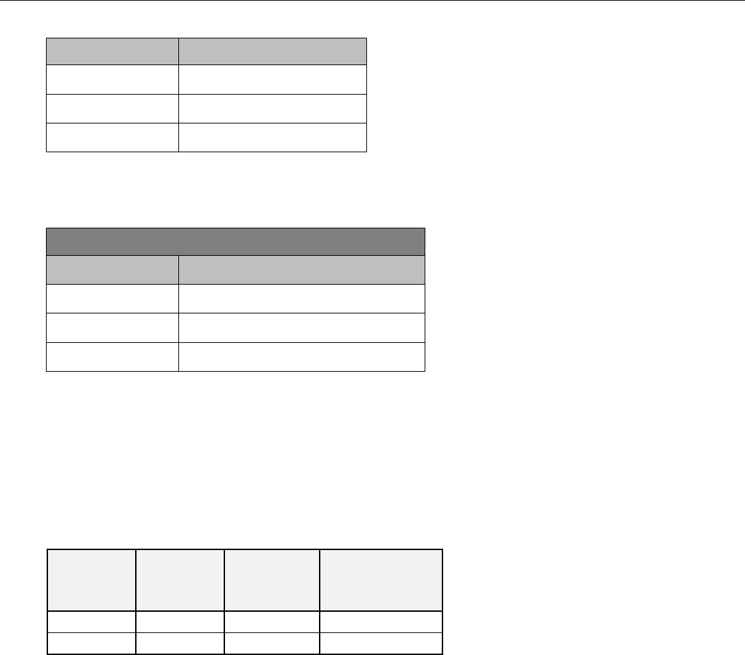
a. System Specifications
Parameter
Range
Frequency
2 – 10,000 Hz
Pulse Width
20μsec – 1msec
Amplitude
0 – 15mA
b. Charger Specifications
The following table contains technical specifications for the Charger.
AC input for the charger:
Parameter
Specification
Frequency
50 to 60 Hz
Voltage
100 to 240 VAC
Input Current
0.2 A max
Additional technical information, including the Guidance and Manufacturer’s Declarations on
electromagnetic emissions and immunity, is available. To request this information, please contact Nevro
Corp.
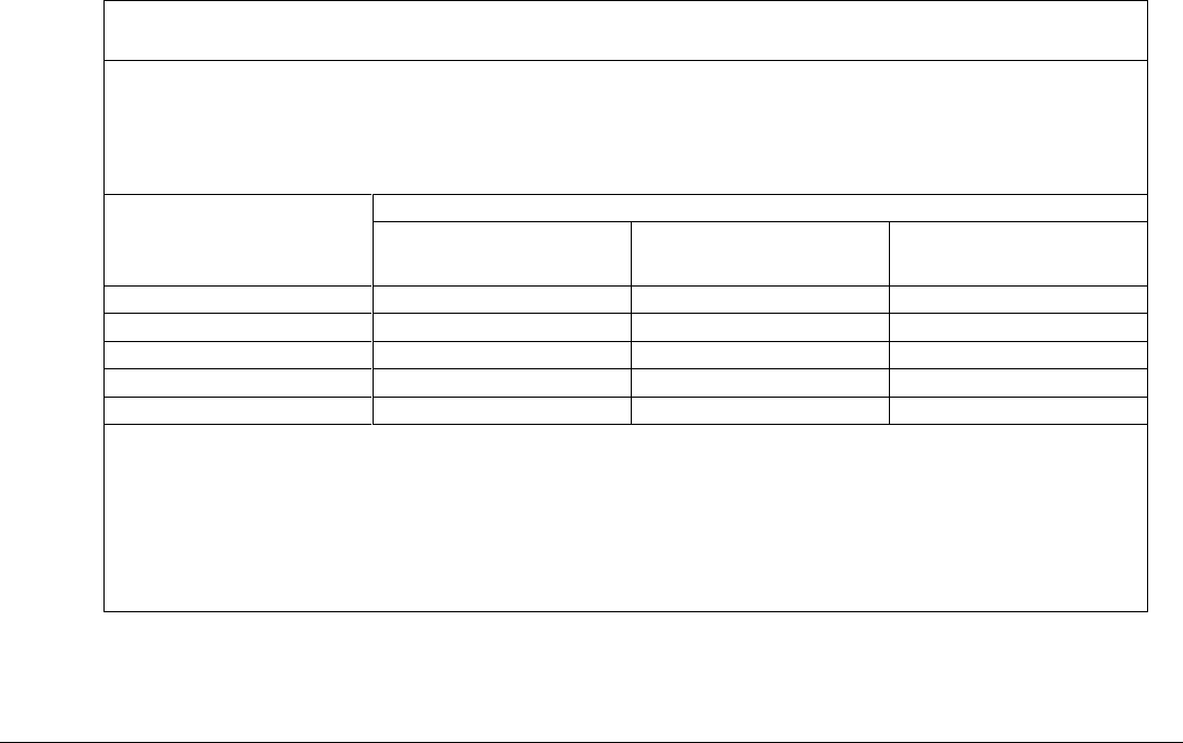
c. Stimulation Parameter Ranges
The following table summarizes the maximum impedance for which the maximum current of 15 mA can
be delivered at the maximum pulse width (1 msec, at a maximum frequency of 400 Hz) and maximum
frequency (10,000 Hz, at a maximum pulse width of 30 µsec).
Frequency
Maximum
Amplitude
Maximum
Pulse
Width
Maximum
Impedance
400 Hz
15 mA
1 msec
1,270 Ω
10,000 Hz
15 mA
30 µsec
1,080 Ω
d. Quality of Wireless Service
The Senza and Senza II systems use a wireless communication system in the MedRadio frequency band
(402-405 MHz). This band is reserved for implantable medical devices. The typical communication range
is less than 5 feet (1.5 meters) between the Patient Remote/Programmer Wand and Implantable Pulse
Generator/Trial Stimulator. Before each communication, the Patient Remote/Programmer Wand scans 8
channels in the band and selects the least interfered channel for communication. All communication is
verified for accuracy. Any communication containing uncorrectable errors are rejected and
communication is retried automatically. If the retries fail, the user is notified of the communication
failure.
e. Wireless Security
The Senza and Senza II systems have a telemetry range of less than 5 feet (1.5 meters). The Patient
Remote is uniquely paired to a specific Implantable Pulse Generator or Trial Stimulator and can only
communicate with that device. The Implantable Pulse Generator or Trial Stimulator will not respond to

Physician Implant Manual 11051 Rev D. DRAFT 17
any communication that does not come from a linked device (a device that is paired with the IPG). There
are additional mechanisms that ensure the integrity of the communicated data.
f. Telemetry Information
The Senza and Senza II systems use a wireless communication system in the MedRadio frequency band
(402-405 MHz). Refer to the Patient Manual for more information on optimizing communication.
Refer to the tables in the “Electromagnetic Interference” section to determine the recommended
separation distances between the Senza or Senza II system and other transmitters.
g. Wireless Charging Information
The Senza and Senza II systems use charging frequency of 410 - 485 kHz. The charging distance between
the Charger and the IPG is between 0 to 2.5 cm. Refer to the instructions provided in the Patient Manual
to optimize charging.
h. Electromagnetic Interference
Guidance and Manufacturer’s Declaration - electromagnetic emissions
The Senza and Senza II Systems are intended for use in the electromagnetic environment specified below. The
customer or user of the Senza or Senza II System should assure that it is used in such an environment.
Emissions Test
Compliance
Electromagnetic Environment Guide
RF emissions CISPR 11
Group 1
The Senza and Senza II Systems use RF energy only for its internal
function. Therefore, its RF emissions are very low and are not
likely to cause any interference in nearby electronic equipment.
RF emissions CISPR 11
Class B
Class A
(Programmer
Wand)
The Senza and Senza II Systems are suitable for use in all
establishments. Including domestic establishments and those
directly connected to the public low-voltage power supply
network that supplies buildings used for domestic purposes.
The Programmer Wand is suitable for use in all establishments
other than domestic and those directly connected to the public
low-voltage power supply network that supplies buildings used for
domestic purposes.
Harmonic emissions
IEC 61000-3-2
Class B
Voltage fluctuations /
Flicker emissions IEC 61000-
3-3
Complies

Physician Implant Manual 11051 Rev D. DRAFT 18
Guidance and Manufacturer’s Declaration - electromagnetic immunity
The Senza and Senza II Systems are intended for use in the electromagnetic environment specified below. The
customer or user of the Senza/Senza II System should assure that it is used in such an environment.
Immunity Test
IEC 60601 Test
Level
Compliance Level
Electromagnetic environment guidance
Electrostatic
discharge (ESD)
IEC 61000-4-2
± 6 kV contact
± 8 kV air
± 6 kV contact
± 8 kV air
Floors should be wood, concrete or ceramic
tile. If floors are covered with synthetic
material, the relative humidity should be at
least 30 %.
Electrical fast
transient/ burst
IEC 61000-4-4
± 2 kV for power
supply lines
± 1 kV for
input/output lines
± 2 kV for power
supply lines
± 1 kV for
input/output lines
Mains power quality should be that of a
typical commercial or hospital environment.
Surge IEC 61000-
4-5
± 1 kV line(s) to
line(s)
± 2 kV line(s) to
earth
± 1 kV line(s) to
line(s)
± 2 kV line(s) to
earth
Mains power quality should be that of a
typical commercial or hospital environment.
Voltage dips,
short
interruptions and
voltage variations
on power supply
input lines IEC
61000-4-11
<5 % UT
(>95 % dip in UT)
for 0.5 cycle
40 % UT
(60 % dip in UT)
for 5 cycles
70 % UT
(30 % dip in UT)
for 25 cycles
<5 % UT
(>95 % dip in UT)
for 5 s
<5 % UT
(>95 % dip in UT)
for 0.5 cycle
40 % UT
(60 % dip in UT)
for 5 cycles
70 % UT
(30 % dip in UT)
for 25 cycles
<5 % UT
(>95 % dip in UT)
for 5 s
Mains power quality should be that of a
typical commercial or hospital environment. If
the user of Senza/Senza II System requires
continued operation during power mains
interruptions, it is recommended that the
Senza/Senza II System be powered from an
uninterruptible power supply or a battery.
Power frequency
(50/60 Hz)
magnetic field IEC
61000-4-8
3 A/m
3 A/m
Power frequency magnetic fields should be at
levels characteristic of a typical location in a
typical commercial or hospital environment.
NOTE UT is the a.c. mains voltage prior to application of the test level.
Physician Implant Manual 11051 Rev D. DRAFT 19
Guidance and Manufacturer’s Declaration - electromagnetic immunity
The Senza and Senza II Systems are intended for use in the electromagnetic environment specified below. The
customer or user of the Senza/Senza II System should assure that it is used in such an environment.
Immunity Test
IEC 60601 Test
Level
Compliance Level
Electromagnetic environment guidance
Conducted RF
IEC 61000-4-6
3 Vrms
150 kHz to 80 MHz
3 Vrms
150 kHz to 80 MHz
Portable and mobile RF communications
equipment should be used no closer to any part
of the Senza/Senza II System, including cables,
than the recommended separation distance
calculated from the equation applicable to the
frequency of the transmitter.
Recommended separation distance :
d=1.2√𝑃
Radiated RF
IEC 61000-4-3
3 V/m 80 MHz to
2.5 GHz
3 V/m
80 M Hz to 2.5 GHz
d=1.2 √𝑃 80 MHz to 800 MHz
d=2.3 √𝑃 800 MHz to 2.5 GHz
where P is the maximum output power rating of
the transmitter in watts (W) according to the
transmitter manufacturer and d is the
recommended separation distance in meters
(m).
Field strengths from fixed RF transmitters, as
determined by an electromagnetic site survey, a
should be less than the compliance level in each
frequency range (b) Interference may occur in
the vicinity of equipment marked with the
symbol shown below:
NOTE: At 80 MHz and 800 MHz, the higher frequency range applies.
NOTE: These guidelines may not apply in all situations. Electromagnetic propagation is affected by absorption
and reflection from structures, objects and people.
a) Field strengths from fixed transmitters, such as base stations for radio (cellular/cordless) telephones and land
mobile radios, amateur radio, AM and FM radio broadcast and TV broadcast cannot be predicted theoretically
with accuracy. To assess the electromagnetic environment due to fixed RF transmitters, an electromagnetic site
survey should be considered. If the measured field strength in the location in which the Senza/Senza II System is
used exceeds the applicable RF compliance level above, the Senza/Senza II System should be observed to verify
normal operation. If abnormal performance is observed, additional measures may be necessary, such as re-
orienting or relocating the Senza/Senza II System.
b) Over the frequency range 150 kHz to 80 MHz, field strengths should be less than 3 V/m.
Physician Implant Manual 11051 Rev D. DRAFT 20
Recommended separation distances between potable and mobile RF communications equipment and
the Senza/Senza II System
The Senza and Senza II Systems are intended for use in an electromagnetic environment in which radiated RF
disturbances are controlled. The customer or the user of the Senza/Senza II System can help prevent
electromagnetic interference by maintaining a minimum distance between portable and mobile RF
communications equipment (transmitters) and the Senza/Senza II System as recommended below, according to
the maximum output power of the communications equipment.
Rated maximum output
power of transmitter
W
Separation distance according to frequency of transmitter (meters)
150 kHz to 80 MHz
d = 1.2 √P
80 MHz to 800 MHz
d = 1.2 √P
800 MHz to 80 GHz
d = 2.3 √P
0.01
0.12
0.12
0.23
0.1
0.37
0.37
0.74
1
1.17
1.17
2.33
10
3.69
3.69
7.38
100
11.67
11.67
23.33
For transmitters rated at a maximum output power not listed above, the recommended separation distance d in
meters (m) can be estimated using the equation applicable to the frequency of the transmitter, where P is the
maximum output power rating of the transmitter in watts (W) according to the transmitter manufacturer.
NOTE: At 80 MHz and 800 MHz, the separation distance for the higher frequency range applies.
NOTE: These guidelines may not apply in all situations. Electromagnetic propagation is affected by absorption and
reflection from structures, objects and people.
8. Patient Identification
Please ensure that the patient receives a completed identification card following surgery.

Physician Implant Manual 11051 Rev D. DRAFT 21
9. Instructions for Use
The physicians providing SCS therapy with the Senza and Senza II systems should be experienced in the
diagnosis and treatment of chronic pain and have proper surgical and clinical training. See sections 10 and 11
below on details for instructions for use.
10. Guidelines for Trial-phase Implantation
This section details the recommended procedures for trial-phase implantation of lead(s).
a. Temporary vs. Permanent Trials
• Physicians may elect to perform a trial in one of two ways, temporary or permanent. Nevro
devices can be used with either method.
• In a temporary trial, the lead is placed in the patient, and the proximal end is externalized and
connected to the Trial Stimulator using a connecting cable, which is referred to as the OR Cable.
When the trial is over, the lead is removed from the patient. Subsequently, when a permanent
system is implanted, the patient receives a new lead and IPG.
o To perform a temporary trial, use the directions in the following sections in the order
below:
1. Pre-op Instructions
2. Lead Placement
3. Performing Intra-operative Testing
4. Preparing for Temporary Trial
5. Connecting the Lead or Extension to the Trial Stimulator
• In a permanent trial, the lead is placed in the patient and then fully implanted. The lead is
attached to a lead extension, which is externalized and connected to the Trial Stimulator using
an OR Cable. With this approach, the implanted lead remains sterile. When a permanent
system is implanted, the extension is discarded and the implanted lead is connected to an IPG.
Depending on the patient body and the lead length that was used, a new lead extension may be
necessary to connect the lead to the selected IPG site.
o To perform a permanent trial, use the directions in the following sections in the order
below:
1. Pre-op Instructions
2. Lead Placement
3. Performing Intra-operative Testing
4. Anchoring the Lead
5. Connecting an Extension to the Lead
6. Percutaneous Tunneling of the Extension
7. Closing the Incision Sites
8. Connecting the Lead or Extension to the Trial Stimulator
b. Pre-op Instructions
• Before opening the packages, verify the use-by date and the description of the component,
such as length and type.
• Do not use any component that shows signs of damage.
• NOTE:

Physician Implant Manual 11051 Rev D. DRAFT 22
o Confirm that the Trial Stimulator has batteries. When inserting batteries into the Trial
Stimulator, match the positive (+) end of the battery to the positive (+) symbol inside
the battery compartment.
o Turn off the Trial Stimulator before taking out the batteries.
o The Trial Stimulator’s battery compartment must remain closed unless the batteries are
actively being replaced.
o The M8 Adaptor (MADP-25B) can be used to connect specific Medtronic leads to the
Nevro Trial Stimulator/IPG. The S8 Adaptor (SADP-25B) can be used to connect specific
St. Jude Medical leads to the Nevro Trial Stimulator/IPG. For a list of compatible leads,
please consult the M8 Adaptor/S8 Adaptor Instructions for Use.
o Adaptors are not required to connect compatible Boston Scientific leads to the Trial
Stimulator. The following Boston Scientific neuromodulation leads and extensions can
be used interchangeably with Nevro’s leads and extensions during the trial phase
implantation and permanent implantation.
1
(Note: xx = length (cm), xxE = length (cm)
Trial Lead)
• SC-2016-xx Infinion™ 16 Lead and Splitter 2x8 Kit
2
• SC-2016-xxE Infinion 16 Lead and Splitter 2x8 Trial Kit
• SC-2138-xx Linear™ xxcm 8 Contact Lead
• SC-2158-xx Linear xxcm 8 Contact Lead
• SC-2158-xxE Linear xxcm 8 Contact Lead
• SC-2208-xx Linear ST xxcm 8 Contact Lead
• SC-2218-xx Linear ST xxcm 8 Contact Lead
• SC-2218-xxE Linear ST xxcm 8 Contact Lead
• SC-2352-xx Linear 3-4 xxcm 8 Contact Lead
• SC-2352-xxE Linear 3-4 xxcm 8 Contact Lead
• SC-2366-xx Linear 3-6 xxcm 8 Contact Lead
• SC-2366-xxE Linear 3-6 xxcm 8 Contact Lead
• SC-3138-xx xxcm 8 Contact Extension
• SC-3304-xx D4 Splitter 2x4
• SC-3354-xx W4 Splitter 2x4
• SC-2316-xx Infinion 16 xxcm 16 Contact Lead Kit
• SC-2316-xxE Infinion 16 xxcm 16 Contact Trial Lead Kit
• SC-3400-xx xxcm Splitter 2x8 Kit
• SC-3138-xx xxcm 8 Contact Extension
• SC-8120-xx Artisan 2x8 Surgical Lead
• SC-8216-xx Artisan 2x8 Surgical Lead
c. Percutaneous Lead Placement
• Prep the skin and drape the patient in a usual sterile fashion.
• Confirm pre-operative antibiotic prophylaxis if deemed appropriate.
• Inject a local anesthetic at the desired needle insertion site.
• Insert the needle at an angle of 45° or less (pointing the needle in the direction of the target
location) into the posterior ligamentous complex at the desired vertebral level using
fluoroscopic guidance.
1
Verification documentation is on file at Nevro Corp.
2
To use Infinion Leads with the Senza/Senza II System, connect the Infinion Lead to the Splitter 2x8.
Physician Implant Manual 11051 Rev D. DRAFT 23
• Remove the needle-stylet from the needle cannula and confirm entry into the epidural space
using standard methods such as loss of resistance. Verify needle location using fluoroscopy.
• In order to advance the lead easier, you may insert the lead blank through the needle and then
withdraw it. Use fluoroscopic guidance.
• Prior to inserting the lead into the needle, ensure that the stylet is fully inserted and extended
to the tip of the lead to ensure optimal steering of the lead.
• With the stylet in the lead, slowly advance the lead into the epidural space.
• Advance the lead to the appropriate vertebral level using fluoroscopic guidance. Rotate the
stylet as necessary to steer the lead.
• NOTE:
o Needles not provided by Nevro Corp. may damage Nevro leads.
o Inserting the lead while the needle is at an angle of greater than 45° may increase
difficulty in placing the lead or damage the lead.
o If you are inserting a second lead, insert the second needle in such a way that doesn’t
damage the first lead.
o If sedation or Monitored Anesthesia Care is used, it is recommended that the patient
remain communicative during needle and lead placement to help mitigate any risk of
neural injury.
d. Surgical Lead Placement
Refer to the Surgical Lead Manual
e. Performing Intra-operative Testing
• After the lead is in the desired location, you are ready to attach the OR Cable to the lead.
• If two leads are used, the leads may be marked using a sterile surgical marker, to distinguish
between the two leads.
• Open the connector box of the OR Cable by pushing the two tabs away from each other. Insert
the proximal end of the lead (or the lead extension) into the connector box.
• When the most proximal contact of the lead is seen in the first notch of the connector box,
close the connector box by pushing the two tabs towards each other.
• The OR Cable is usually not long enough to reach outside the sterile field, so an OR Cable
Extension may need to be attached using an OR Cable Extension Connector. The OR Cable
Extension is designed for temporary connection to the OR Cable to facilitate stimulation testing
outside of the sterile field.
• Ensure that the Trial Stimulator is off.
• Connect the OR Cable or the OR Cable Extension to the Trial Stimulator.
• Conduct impedance testing.
• Verify lead position. Paresthesia mapping is not required for 10 kHz programming.
o If frequencies up to 1200 Hz are used for programming, paresthesia mapping is needed.
For paresthesia mapping, use the following directions.
1. Ensure that the patient can give immediate feedback.
2. Conduct test stimulation. Select contacts and adjust amplitude, pulse width, and
pulse rate until patient has satisfactory paresthesia coverage of the pain areas.
3. If satisfactory paresthesia coverage cannot be achieved, reposition the leads as
necessary and repeat stimulation.
4. Repeat steps 2-3 as needed.
• Turn off the Trial Stimulator and disconnect the lead from the OR Cable.
• At this point, you can opt to do a temporary lead trial or a permanent lead trial.
• CAUTION:
Physician Implant Manual 11051 Rev D. DRAFT 24
o Do not immerse the OR cable connector or plug in water or other liquids. Wipe fluids
(e.g. blood) off the exposed lead connections to ensure that it is dry.
o The OR Cable Assembly is intended for one-time only use. Do not re-sterilize.
o Always turn the Trial Stimulator off before connecting or disconnecting the Cable
Assemblies.
o Do not pull on the OR cable while it is connected to the placed lead.
f. Preparing for Temporary Trial
• Using minimal force, carefully withdraw the insertion needle from the patient while holding the
percutaneous lead.
• Using minimal force, carefully withdraw the stylet while holding the percutaneous lead.
• After removing the needle and the stylet, it is recommended that you confirm the location of
the lead using fluoroscopy.
• Secure the lead to the skin using sterile tape or suturing to the skin. If you are suturing the lead
to the skin, use a non-absorbable suture and the supplied anchoring device. Tying sutures
directly to the lead can damage the lead.
• NOTE: Percutaneous leads are suggested for temporary trial use when implantation of a
surgical lead for permanent stimulation is planned. Refer to the Surgical Lead Manual for details on
surgical lead placement.
g. Anchoring the Lead
• After assuring appropriate anesthesia, make a longitudinal incision around the needle and use a
combination of sharp and blunt dissection to access the supraspinous ligament.
• Using minimal force, carefully withdraw the insertion needle from the patient while holding the
lead.
• Using minimal force, carefully withdraw the stylet while holding the lead.
• After removing the needle and the stylet, it is recommended that you confirm the location of
the lead using fluoroscopy. Place suture(s) over the anchor.
o For a silicone anchor:
At least one suture is needed (two are recommended) to tie the lead anchor to the
lead, and another suture is needed to attach the lead anchor and lead to the patient’s
tissue.
1. Slide the lead anchor over the lead and to the supraspinous ligament.
2. Use a non-absorbable suture(s) to tie the lead anchor to the lead. Tie the suture
around a groove or over the bumps on the lead anchor to prevent the lead from
sliding.
3. Suture the lead anchor to the supraspinous ligament or deep fascial tissue. Run
the suture through the eyelets on the lead anchor or around the bumps or
grooves of the lead anchor. Make sure the suture is firm enough to hold the
anchor to the tissue.
o For an active anchor:
At least one suture is needed (two is recommended) to attach the lead anchor to the
tissue.
1. Slide the lead anchor over the lead and to the supraspinous ligament.
2. Use non-absorbable suture(s) to attach the lead anchor to the patient’s tissue.
Suture the lead anchor to the supraspinous ligament or deep fascial tissue. Run
the suture through the eyelets on the lead anchor or around the grooves of the
lead anchor. Make sure the suture is firm enough to hold the lead anchor to the
tissue.
Physician Implant Manual 11051 Rev D. DRAFT 25
3. Use the supplied torque wrench to tighten the anchor to the lead. Tighten the
torque wrench in clockwise direction until the audible click is heard.
• CAUTION:
o Tying sutures directly on the lead can damage the lead. Always use a lead anchor(s).
o Do not use polypropylene sutures as they may damage the lead anchor.
o Do not use a hemostat on the lead body. This may damage the lead insulation.
o If needed, it is recommended that bipolar electrocautery is used for hemostasis around
the epidural needles. Energy from monopolar cauterization could conduct down the
needle to the epidural space and damage the neural structures.
o If the lead does not fully insert into the active anchor, loosen the anchor by turning the
torque wrench counter-clockwise and then re-insert the lead.
o Use only the appropriate torque wrench provided by Nevro Corp.
h. Connecting an Extension to the Lead
• Wipe fluids (e.g. blood) from the proximal end of the lead. Then fully insert the proximal end of
the lead into the lead extension’s connector.
• Do an impedance check.
• Do not tighten the setscrew on the extension until all of the impedances are in the normal
range.
• Fully insert the torque wrench into the setscrew.
• Rotate the torque wrench handle to turn the lead extension connector’s setscrew clockwise
until it clicks. Clicking indicates that it is fully tightened.
• NOTE:
o Ensure that the setscrew is not removed from the connector.
o If the lead does not fully insert into the lead extension’s connector, check to see
whether the setscrew is impeding the progress of the lead. If it is, use the torque
wrench to loosen the setscrew by turning it counter-clockwise and then re-insert the
lead.
o If the setscrew does not tighten smoothly, try the following:
1. Use the torque wrench to loosen the setscrew by turning it counter-clockwise
and then re-tighten by turning it clockwise.
2. Check to see that the lead is fully inserted into the lead extension’s connector
before tightening.
o The wrench is torque-limited and cannot be over tightened if you use the handle.
o Use only the appropriate Nevro torque wrench to ensure that the proper torque is
applied to the setscrews.
i. Percutaneous Tunneling of the Extension
• Assemble the tunneling tool by screwing in one of the tips on the end of the shaft. Make sure
the straw is on the shaft prior to screwing in the tip.
• Plan the desired route of the tunnel and mark the route and the destination point at least 10-15
cm from the incision.
• Give appropriate local anesthetic along the tunneling route.
• Create a small incision at the planned extension exit site.
• Insert the tunneling tool from the lead insertion site and create a subcutaneous tunnel to the
extension exit site until the straw can be seen.
• Hold the tunneling tip firmly and then unscrew and remove the tunneling tip. Take care not to
drop the tunneling tip.
• Remove the tunneling tool while leaving the straw in the tunnel.

Physician Implant Manual 11051 Rev D. DRAFT 26
• Insert the proximal end of the lead extension(s) through the straw.
• Push the lead extension(s) until they come out of the straw’s other end.
• Gently pull the extension(s) to get as much of the extension(s) that you need through the straw,
and then withdraw the straw from the exit site. It is recommended that a strain relief loop is
left in the dorsal wound.
• Make sure that the lead location has not changed.
• NOTE: In place of the tunneling tool, the following Codman Disposable Catheter Passers may be
used using the standard technique: REF 82-1515 (36cm); REF 82-1516 (55cm); REF 82-1517
(65cm).
j. Closing the Incision Sites
• At the lead insertion site, use blunt dissection to create a pocket large enough to place excess
lead. Coil excess lead into small loops and place them in the pocket.
• Gently pull on the lead extension from the exit site to remove excess slack.
• Close the incision at the lead insertion site.
• A small suture may be used to close the incision at the exit site. Do not tighten a suture around
the lead or lead extension.
• Create a stress relief loop outside the body and tape it to the skin.
• Appropriate sterile dressings must be applied to the site where the lead or lead extension exits
the body.
k. Connecting the Lead or Extension to the Trial Stimulator
• Appropriate sterile dressings must be applied to the site where the lead or lead extension exits
the body. Tape the lead securely to the skin.
• Connect the lead or lead extension to the OR Cable.
• Create a loop of the OR Cable for strain relief and then tape the OR Cable to the skin.
• Connect the OR Cable to the Trial Stimulator.
11. Guidelines for Permanent Implantation
This section details the recommended procedures for permanent implant-phase.
a. Pre-op instructions
• Before opening the packages, verify the use-by date and the description of the component,
such as length and type.
• Do not use any component that shows signs of damage.
• Ensure that the IPG is charged prior to implant
b. If the patient was given a temporary trial
• NOTE: At the end of a temporary trial, remove the temporary trial lead(s) as described below
and follow the “IPG Implantation” section below. The leads will typically be removed before a
patient comes in for the permanent implant.
• Removing the temporary trial lead(s):
o Clip sutures if they were used to secure the lead(s) in place.
o Remove the lead(s) and discard.
• Place lead(s) by following previous sections for:
1. Pre-op Instructions
2. Lead Placement
Physician Implant Manual 11051 Rev D. DRAFT 27
3. Performing Intra-operative Testing
4. Anchoring the Lead
• Prepare the IPG implant site and tunnel the lead to the IPG site by following the instructions
below:
o Prepare the skin and drape in the usual sterile fashion.
o With consideration for patient comfort and infection control, identify a desired IPG
implant site away from the exit site for the lead extension used for the trial.
o Anesthetize the site for the IPG pocket.
o Use the IPG template to estimate the size of the pocket. Mark the IPG implant site and
make an incision that would be adequate to insert the IPG.
o Create a subcutaneous pocket using blunt dissection. The pocket should be no larger
than the IPG and no deeper than a depth of 2 cm from the skin.
o NOTE:
1. For optimal charging, the IPG must be no more than 2 cm from the surface of the
skin.
2. Deep tunneling is not recommended.
o Assemble the tunneling tool by screwing in one of the tips on the end of the shaft. Make
sure the straw is on the shaft.
o Mark the desired tunneling route.
o Give appropriate local anesthetic along the tunneling route.
o If necessary, gently bend the shaft of the tunneling tool to conform to the patient’s
anatomy.
o Create a subcutaneous tunnel between the IPG implant site and the lead anchor site.
Insert the tunneling tool until the tip of the straw is out of the tunnel.
o Hold the tunneling tip firmly and then unscrew and remove the tunneling tip. Take care
not to drop the tunneling tip.
o Remove the tunneling tool’s tip. Remove the tunneling tool, while leaving the straw in
the tunnel.
o If necessary, use a lead extension. (Refer to the previous section on “Connecting an
Extension to the Lead”)
o Insert the proximal end of the lead(s) or lead extension(s) through the straw.
o Push the lead(s) or lead extension(s) until they come out of the straw’s other end.
o Gently pull the lead to get as much of the lead that you desire through the straw, and
then carefully withdraw the straw. It is recommended that a strain relief loop is left in
the dorsal wound.
o Make sure that the lead location has not changed.
• Follow the instruction on IPG Implantation below.
c. If the patient was given a Permanent trial
• NOTE: At the end of a permanent trial, remove the lead extension(s) as described below and
follow the “IPG Implantation” section below.
• Removing the lead extension(s):
o Prepare the skin and prep the patient in the usual sterile fashion. It is recommended to
prep the midline incision in the sterile field and leave the extension site outside the
sterile field so that it can be removed by an OR assistant.
o Open the midline incision.
o Cut the lead extension at the connector at the lead insertion site. Confirm that you are
cutting the lead extension, not the lead.
Physician Implant Manual 11051 Rev D. DRAFT 28
o Use the torque wrench to loosen the setscrew in the lead extension connector.
Disconnect the head of the lead extension.
o Remove the lead extension by pulling on the portion of the lead extension that is
already externalized. This will be done outside the sterile field.
o Discard the head of the lead extension.
• Prepare the IPG implant site and tunnel the lead to the IPG site by following the instructions
below:
o With consideration for patient comfort and infection control, identify a desired IPG
implant site away from the exit site for the lead extension used for the trial.
o Anesthetize the site for the IPG pocket
o Mark the IPG implant site and make an incision equal to the IPG’s width.
o Create a subcutaneous pocket using blunt dissection. The pocket should be no larger
than the IPG and no deeper than a depth of 2 cm from the skin.
o NOTE:
1. For optimal charging, the IPG must be no more than 2 cm from the surface of the
skin.
2. Deep tunneling is not recommended.
3. In place of the tunneling tool, the following Codman Disposable Catheter Passers
may be used using the standard technique: REF 82-1515 (36cm); REF 82-1516
(55cm); REF 82-1517 (65cm).
o Assemble the tunneling tool by screwing in one of the tips on the end of the shaft. Make
sure the straw is on the shaft.
o Mark the desired tunneling route.
o Give appropriate local anesthetic along the tunneling route.
o If necessary, gently bend the shaft of the tunneling tool to conform to the patient’s
anatomy.
o Create a subcutaneous tunnel between the IPG implant site and the lead anchor site.
Insert the tunneling tool until the tip of the straw is out of the tunnel.
o Hold the tunneling tip firmly and then unscrew and remove the tunneling tip. Take care
not to drop the tunneling tip.
o Remove the tunneling tool’s tip. Remove the tunneling tool, while leaving the straw in
the tunnel.
o If necessary, use a lead extension. (Refer to the previous section on “Connecting an
Extension to the Lead”)
o Insert the proximal end of the lead(s) or lead extension(s) through the straw.
o Push the lead(s) or lead extension(s) until they come out of the straw’s other end.
o Gently pull the lead to get as much of the lead or lead extension that you desire through
the straw, and then carefully withdraw the straw. It is recommended that a strain relief
loop is created.
o Make sure that the lead location has not changed.
• Follow the instruction on IPG Implantation below.
d. IPG Implantation
• Confirm that no homeostasis is required.
• The IPG should not be exposed to electrocautery. If the use of electrocautery is necessary, turn
off the IPG and use bipolar electrocautery. Do not use monopolar electrocautery.
• Wipe the proximal end of the lead(s) or lead extension(s).
Physician Implant Manual 11051 Rev D. DRAFT 29
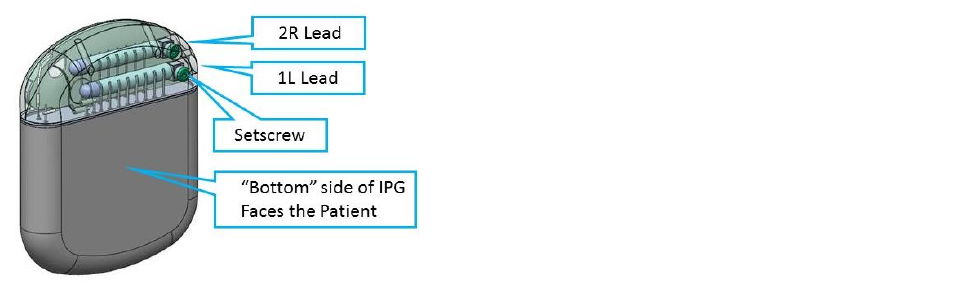
• The most cephalad or left lead or lead extension connects to IPG port 1L. The most caudal or
right lead or lead extension connects to IPG port 2R.
• Place the lead(s) or lead extension(s) fully into the header port and perform impedance check.
• NOTE:
o When using two leads, connect the left lead or lead extension to IPG port 1L. Then,
connect the right lead or lead extension to IPG port 2R.
o When using one lead, start by placing the port plug in the 2R port of the IPG and tighten
the setscrew. Then insert the lead into IPG port 1L. It is recommended not to tighten the
setscrew until the lead is fully inserted in the 1L port and impedance check has been
performed.
o If any of the contacts have unusually high impedance, re-insert the lead or lead
extension into the header.
• Insert the torque wrench through the septum in the IPG header and fully into the setscrew
socket. The torque wrench will be exactly perpendicular to the broad side of the IPG when
properly aligned.
• Turn the torque wrench’s handle clockwise until it clicks. Clicking indicates that it is fully
tightened.
• NOTE:
o Ensure that the setscrew is not removed from the header.
o If the lead or lead extension does not fully insert into the IPG header, check to see
whether the setscrew is not impeding the progress of the lead or lead extension. If it is,
use the torque wrench to loosen the setscrew by turning it counter-clockwise and then
re-insert the lead or lead extension. Check every full turn of the torque wrench to guard
against completely pulling out the setscrew.
o If the setscrew does not tighten smoothly, try the following:
1. Use the torque wrench to loosen the setscrew by turning it counter-clockwise
and then re-tighten by turning it clockwise.
2. Check to see that the lead or lead extension is fully inserted into the IPG header
before tightening. Check impedance again before tightening.
o The wrench cannot be over tightened if you use the handle.
o The lead or lead extension could be damaged if the setscrew is tightened without being
fully inserted.
o Use only the appropriate Nevro torque wrench.
• Place the IPG in the subcutaneous pocket with "This Side Up" facing towards the skin.
• It is recommended that non-absorbable sutures are placed through the suture holes in the IPG
header and attached to the patient.
• Check communications between the IPG and the programmer prior to closing the IPG pocket
wound. This can be done by taking an impedance measurement.
• Close all wounds and apply dressings in the usual surgical manner.

Physician Implant Manual 11051 Rev D. DRAFT 30
e. IPG Explant or Replacement
• Turn off the IPG.
• Surgically open the IPG pocket and withdraw the device.
• It is recommended that electrocautery not be used until the IPG is removed from the patient
and the leads or extensions disconnected from the IPG. If the use of electrocautery is necessary
while the IPG is still implanted, use bipolar electrocautery. Do not use monopolar
electrocautery.
• Unscrew the connector setscrews to release and disconnect the leads or extensions.
• For replacement, connect a new IPG to the leads or extensions. To discontinue therapy,
surgically remove the implanted lead system.
• NOTE:
o Be careful not to cut the lead(s) or extension(s) when making an incision to remove the
IPG.
12. Device Information for the Clinical Staff
a. Trial Stimulator
Locking and Unlocking the Trial Stimulator
• NOTE: When the buttons on the Trial Stimulator are not pressed for longer than 1 minute, the
Trial Stimulator will “lock”. Only the red button, which turns the stimulation off, is operable
when the Trial Stimulator is in the locked mode.
• Unlocking the Trial Stimulator: To unlock, press and hold both the ‘+’ and ‘-‘ buttons
simultaneously on the Trial Stimulator for longer than 2 seconds. The Trial Stimulator will beep
once for 1 second when it is unlocked.
b. Rechargeable IPG
• The Senza and Senza II IPGs are rechargeable. Nevro recommends a recharge schedule that fits
the patient’s schedule and lifestyle while maintaining sufficient charge to deliver a desired level
of stimulation.
• The rechargeable implant battery should provide at least 10 years of service on typical 10 kHz
program stimulation settings.
3
If lower power stimulation parameters are used to deliver
therapy, the battery should provide service for a longer period of time. At power levels higher
than typical settings, the years of service may be shorter for the IPG.
• With repeated charging over time, the IPG battery will gradually lose its ability to recover its full
capacity. When the patient cannot maintain therapy with daily charging, the IPG may need to
be replaced.
Refer to the Patient Manual (Document number: 11052) for detailed instructions on the Trial
Stimulator, Patient Remote Control, and Charging system.
Refer to the 1.5T and 3T MRI Guidelines (Document number: 11095) for detailed information on MRI as
it pertains to the Senza and Senza II systems.
3
Testing on file at Nevro Corp.
NEVRO CORP.
All questions or concerns about Nevro Corp. products should be forwarded to:
Nevro Corp.
1800 Bridge Parkway
Redwood City, CA 94065
USA
Tel: +1.650.251.0005
Fax: +1.650.251.9415
Email: info@nevro.com