New Centurion Solutions NCS02010910 HANDHELD SECURITY DEVICE User Manual Project 623
New Centurion Solutions, Inc. HANDHELD SECURITY DEVICE Project 623
Contents
- 1. Users Manual
- 2. Users Manual HUB
- 3. HUB Assembly Manual
Users Manual HUB
THE INFORMATION CONTAINED HEREIN IS PROPRIETARY TO NEW CENTURION SOLUTIONS, INC. AND SHALL NOT BE
REPRODUCED OR DISCLOSED IN WHOLE OR IN PART FOR ANY DESIGN OR MANUFACTURE EXCEPT WHEN SUCH USER
POSSESSES DIRECT, WRITTEN AUTHORIZATION FROM NEW CENTURION SOLUTIONS, INC.
Elliott Tech, LLC
HUB Installation Manual
HUB
New Centurion Solutions
Project Number: 776
Reference: 776-91-05-REV-HUB_INSTALLATION_MANUAL.docx
Original Document: March 1, 2011
Revision A: March 16, 2011
Prepared for:
Prepared by:
New Centurion Solutions, Inc.
Greg Williams
3011 Spring Garden St.
Suite E
Greensboro, NC 27403
(336) 617-5410
GWilliams@newcenturionsolutions.com
Elliott Tech, LLC
346 Raleigh Street
Holly Springs, NC 27540
(919) 342-6899
(888) 631-1795 Fax
s.elliott@elliotttech.com

HUB Installation Manual 776-91-05-REV-A_HUB_INSTALLATION_MANUAL.docx
THE INFORMATION CONTAINED HEREIN IS PROPRIETARY TO NEW CENTURION SOLUTIONS, INC. AND SHALL NOT BE
REPRODUCED OR DISCLOSED IN WHOLE OR IN PART FOR ANY DESIGN OR MANUFACTURE EXCEPT WHEN SUCH USER
POSSESSES DIRECT, WRITTEN AUTHORIZATION FROM NEW CENTURION SOLUTIONS, INC.
ii
Revision Page
Rev
Description
Section
A
FCC Notification
3

HUB Installation Manual 776-91-05-REV-A_HUB_INSTALLATION_MANUAL.docx
THE INFORMATION CONTAINED HEREIN IS PROPRIETARY TO NEW CENTURION SOLUTIONS, INC. AND SHALL NOT BE
REPRODUCED OR DISCLOSED IN WHOLE OR IN PART FOR ANY DESIGN OR MANUFACTURE EXCEPT WHEN SUCH USER
POSSESSES DIRECT, WRITTEN AUTHORIZATION FROM NEW CENTURION SOLUTIONS, INC.
iii
Contents
1. Equipment List ......................................................................................................... 4
2. Installation Instructions .......................................................................................... 5
3. FCC Notification ...................................................................................................... 6
HUB Installation Manual 776-91-05-REV-A_HUB_INSTALLATION_MANUAL.docx
THE INFORMATION CONTAINED HEREIN IS PROPRIETARY TO NEW CENTURION SOLUTIONS, INC. AND SHALL NOT BE REPRODUCED OR
DISCLOSED IN WHOLE OR IN PART FOR ANY DESIGN OR MANUFACTURE EXCEPT WHEN SUCH USER POSSESSES DIRECT, WRITTEN
AUTHORIZATION FROM NEW CENTURION SOLUTIONS, INC.
4
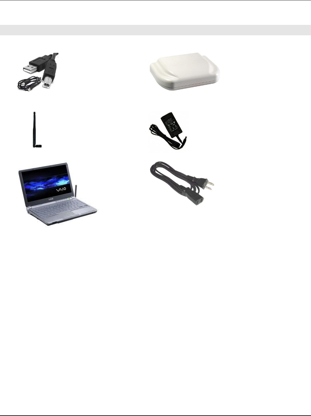
1. EQUIPMENT LIST
A. USB Cable, Type A to Type B (1)
B. Hub Assembly (1)
C. Flexible ½ wave center-fed dipole antenna
with articulated knuckle (1)
D. HUB Power Supply (1)
E. Personal Computer (PC) (1)
F. U.L. approved power cord, 6 ft. length (1)
HUB Installation Manual 776-91-05-REV-A_HUB_INSTALLATION_MANUAL.docx
THE INFORMATION CONTAINED HEREIN IS PROPRIETARY TO NEW CENTURION SOLUTIONS, INC. AND SHALL NOT BE REPRODUCED OR
DISCLOSED IN WHOLE OR IN PART FOR ANY DESIGN OR MANUFACTURE EXCEPT WHEN SUCH USER POSSESSES DIRECT, WRITTEN
AUTHORIZATION FROM NEW CENTURION SOLUTIONS, INC.
5
2. INSTALLATION INSTRUCTIONS
To begin, check the parts available against the equipment list, identifying any missing parts. If all
parts are accounted for, proceed to the instructions below to begin installing the HUB.
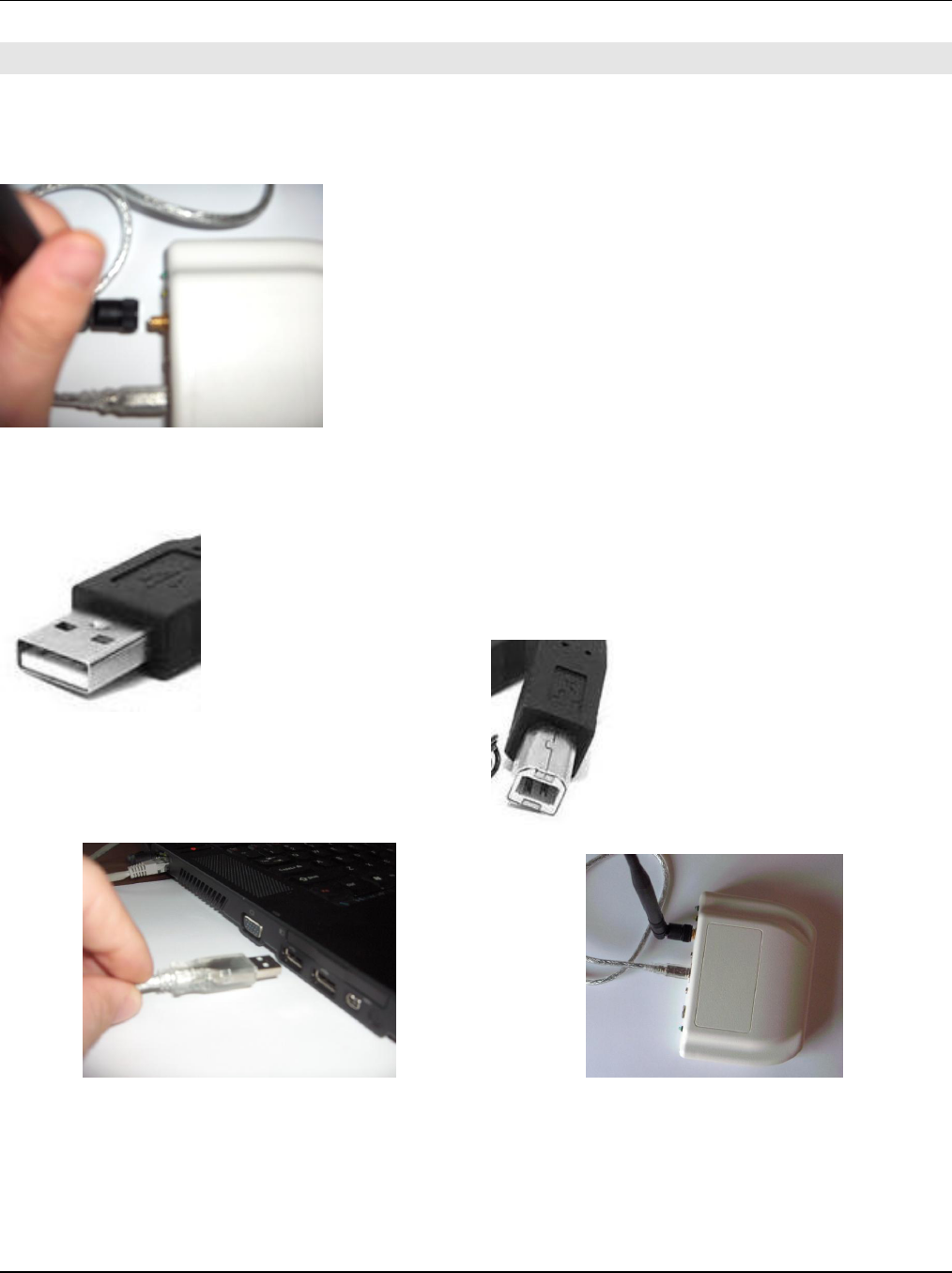
Step 1: Identify the Flexible ½ wave center-fed dipole antenna
with articulated knuckle (C). Screw the antenna into the gold
coaxial antenna connector on the front panel of the HUB
assembly (B). Ensure that the antenna is screwed onto the
connector snugly, but take care not to over-tighten the antenna
as it will damage the connector or the HUB assembly front
panel.
Step 2: Identify the USB Cable, Type A to Type B (A). The type-A end of
the cable is smaller and flatter than the type-B end of the cable and will
mate with a standard USB port on a PC. Plug this end into one of the USB
ports on the Personal Computer (PC) (E). Plug the other end (Type-B) into
the mating USB connector on the front panel of the HUB assembly (B).
Type-A
Type-B
HUB Installation Manual 776-91-05-REV-A_HUB_INSTALLATION_MANUAL.docx
THE INFORMATION CONTAINED HEREIN IS PROPRIETARY TO NEW CENTURION SOLUTIONS, INC. AND SHALL NOT BE REPRODUCED OR
DISCLOSED IN WHOLE OR IN PART FOR ANY DESIGN OR MANUFACTURE EXCEPT WHEN SUCH USER POSSESSES DIRECT, WRITTEN
AUTHORIZATION FROM NEW CENTURION SOLUTIONS, INC.
6
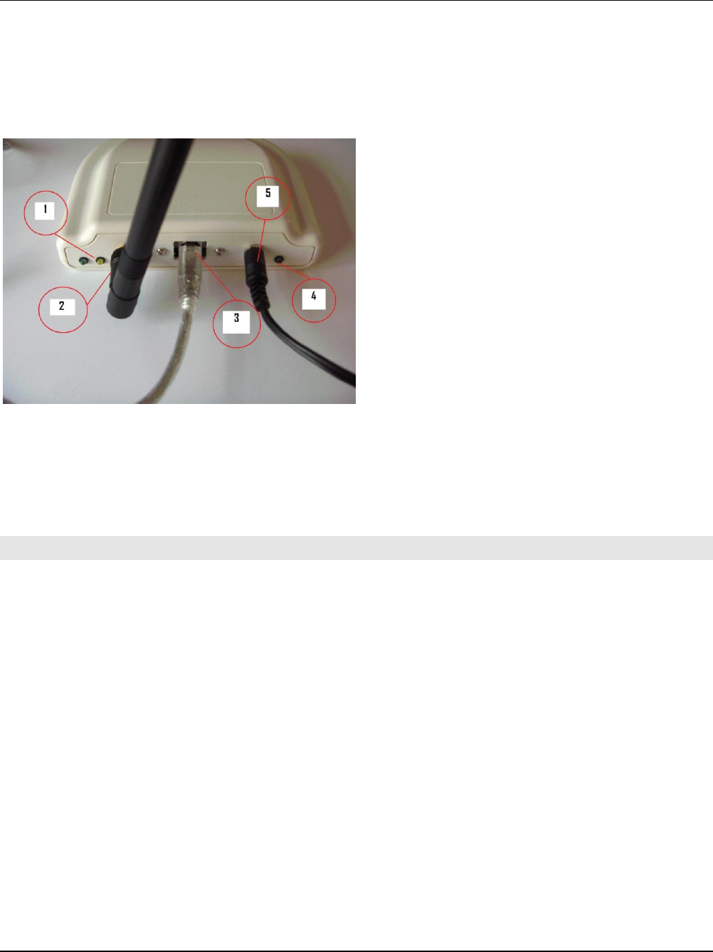
Step 3: Identify the HUB Power Supply (D). Plug the barrel jack plug into the mating barrel jack
on the front panel of the HUB assembly (B). Plug the U.L. approved power cord, 6 ft. length (F)
into the HUB Power Supply (D). Only one end will mate with it properly. Plug the other end of the
power cord into a standard 120 Volt wall outlet. The green light on the front panel of the HUB
should illuminate.
1 – Green status indicator light / yellow status
indicator light
2 – Flexible ½ wave center-fed dipole antenna
with articulated knuckle
3 – USB cable type-B end, plugged into the
HUB assembly
4 – Green power indicator light – this should
illuminate whenever the HUB is correctly
connected to a power source
5 – Barrel jack plug of HUB Power Supply (D),
plugged into the barrel jack of the HUB
assembly
3. FCC NOTIFICATION
NOTE: THE MANUFACTURER IS NOT RESPONSIBLE FOR ANY RADIO OR TV INTERFERENCE
CAUSED BY UNAUTHORIZED MODIFICATIONS TO THIS EQUIPMENT. SUCH MODIFICATIONS
COULD VOID THE USER’S AUTHORITY TO OPERATE THE EQUIPMENT.
THIS DEVICE COMPLIES WITH PART 15 OF THE FCC RULES. OPERATION IS SUBJECT TO THE
FOLLOWING TWO CONDITIONS: (1) THIS DEVICE MAY NOT CAUSE HARMFUL INTERFERENCE, AND
(2) THIS DEVICE MUST ACCEPT ANY INTERFERENCE RECEIVED, INCLUDING INTERFERENCE THAT
MAY CAUSE UNDESIRED OPERATION.