New Centurion Solutions NCS04010910 HANDHELD SECURITY DEVICE User Manual Project 623
New Centurion Solutions, Inc. HANDHELD SECURITY DEVICE Project 623
UserManual.wiki
>
New Centurion Solutions
>
NCS04010910 User Manual
>
Users Manual
Contents
1.
Users Manual
2.
Installation Manual
3.
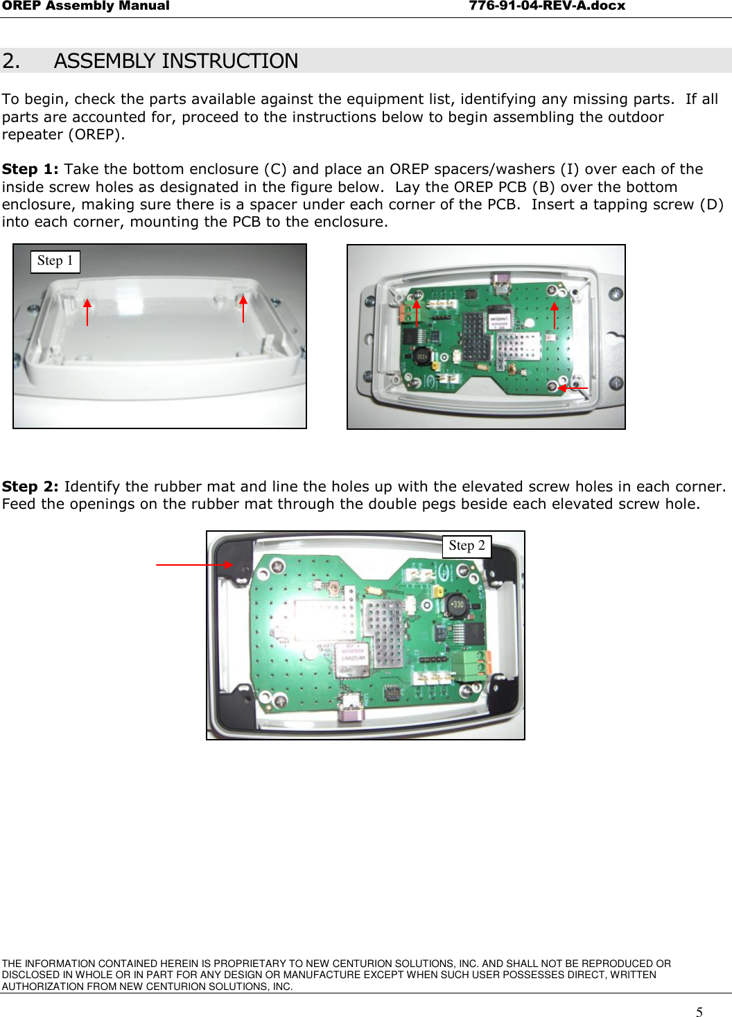
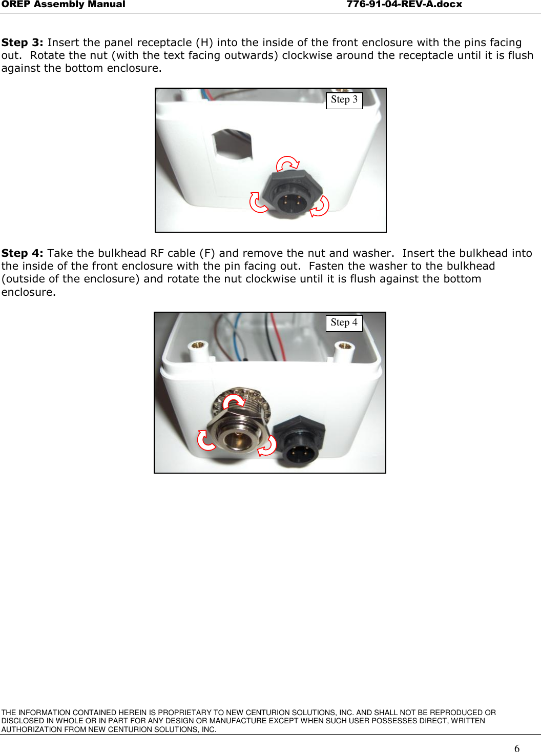
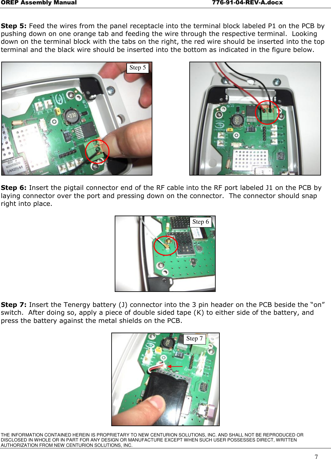
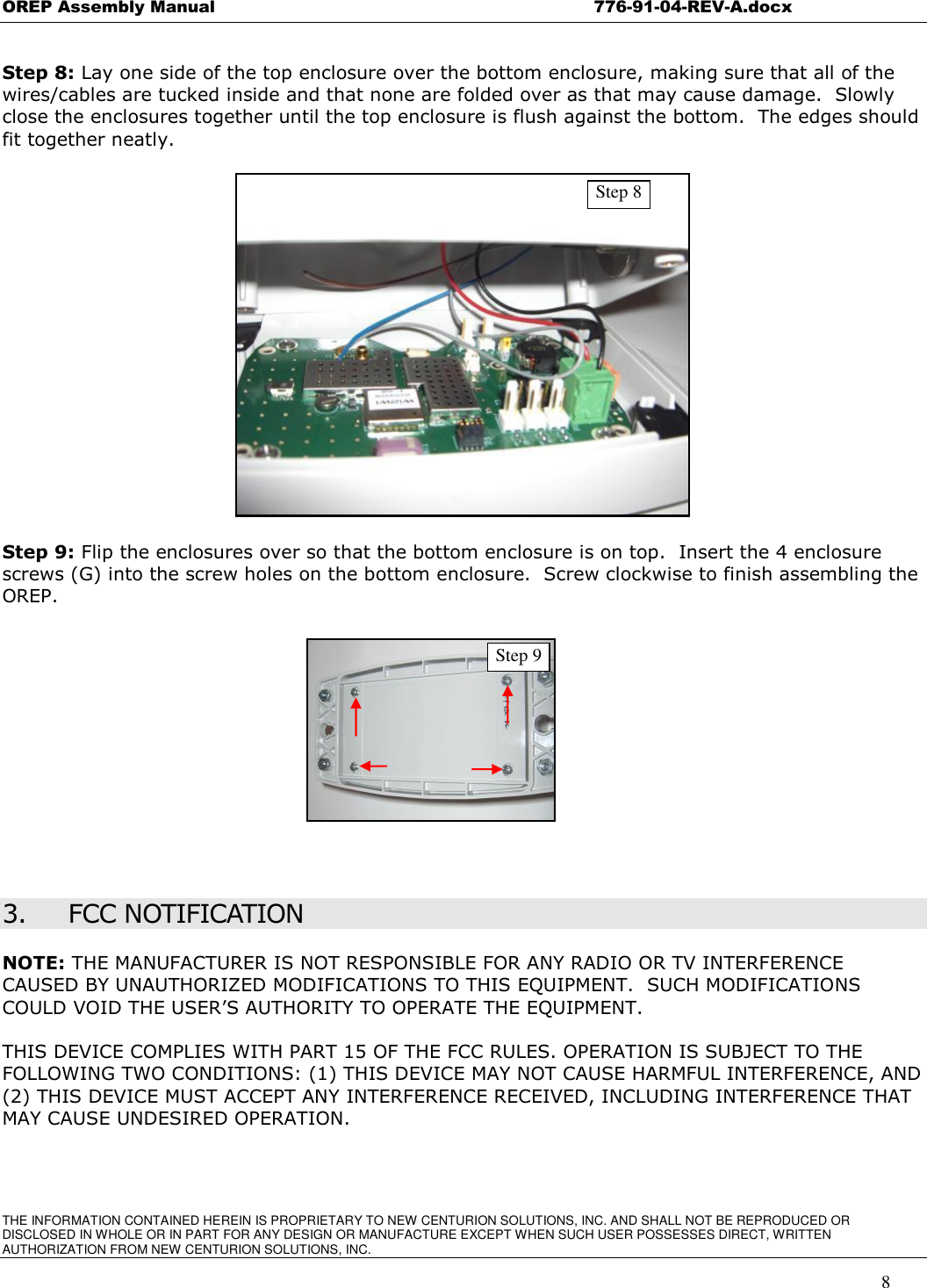
Assembly Manual
Users Manual
Navigation menu
Upload a User Manual
Namespaces
Wiki Guide
HTML
PDF
Info
Views
User Manual
Discussion / Help
Navigation