New Centurion Solutions NCS04010910 HANDHELD SECURITY DEVICE User Manual Project 623
New Centurion Solutions, Inc. HANDHELD SECURITY DEVICE Project 623
Contents
- 1. Users Manual
- 2. Installation Manual
- 3. Assembly Manual
Users Manual
THE INFORMATION CONTAINED HEREIN IS PROPRIETARY TO NEW CENTURION SOLUTIONS, INC. AND SHALL NOT BE
REPRODUCED OR DISCLOSED IN WHOLE OR IN PART FOR ANY DESIGN OR MANUFACTURE EXCEPT WHEN SUCH USER
POSSESSES DIRECT, WRITTEN AUTHORIZATION FROM NEW CENTURION SOLUTIONS, INC.
Elliott Tech, LLC
OREP Assembly Manual
OREP
New Centurion Solutions
Project Number: 776
Reference: 776-91-04-REV-.docx
Original Document: March 1, 2011
Revision A: March 16, 2011
Prepared for:
Prepared by:
New Centurion Solutions, Inc.
Greg Williams
3011 Spring Garden St.
Suite E
Greensboro, NC 27403
(336) 617-5410
Gwilliams@newcenturionsolutions.com
Elliott Tech, LLC
346 Raleigh Street
Holly Springs, NC 27540
(919) 342-6899
(888) 631-1795 Fax
s.elliott@elliotttech.com

OREP Assembly Manual 776-91-04-REV-A.docx
THE INFORMATION CONTAINED HEREIN IS PROPRIETARY TO NEW CENTURION SOLUTIONS, INC. AND SHALL NOT BE
REPRODUCED OR DISCLOSED IN WHOLE OR IN PART FOR ANY DESIGN OR MANUFACTURE EXCEPT WHEN SUCH USER
POSSESSES DIRECT, WRITTEN AUTHORIZATION FROM NEW CENTURION SOLUTIONS, INC.
ii
Revision Page
Rev
Description
Section
A
FCC Notification
3

OREP Assembly Manual 776-91-04-REV-A.docx
THE INFORMATION CONTAINED HEREIN IS PROPRIETARY TO NEW CENTURION SOLUTIONS, INC. AND SHALL NOT BE
REPRODUCED OR DISCLOSED IN WHOLE OR IN PART FOR ANY DESIGN OR MANUFACTURE EXCEPT WHEN SUCH USER
POSSESSES DIRECT, WRITTEN AUTHORIZATION FROM NEW CENTURION SOLUTIONS, INC.
iii
Contents
1. Equipment List ......................................................................................................... 4
2. Assembly Instruction................................................................................................ 5
3. FCC Notification ...................................................................................................... 8
OREP Assembly Manual 776-91-04-REV-A.docx
THE INFORMATION CONTAINED HEREIN IS PROPRIETARY TO NEW CENTURION SOLUTIONS, INC. AND SHALL NOT BE REPRODUCED OR
DISCLOSED IN WHOLE OR IN PART FOR ANY DESIGN OR MANUFACTURE EXCEPT WHEN SUCH USER POSSESSES DIRECT, WRITTEN
AUTHORIZATION FROM NEW CENTURION SOLUTIONS, INC.
4
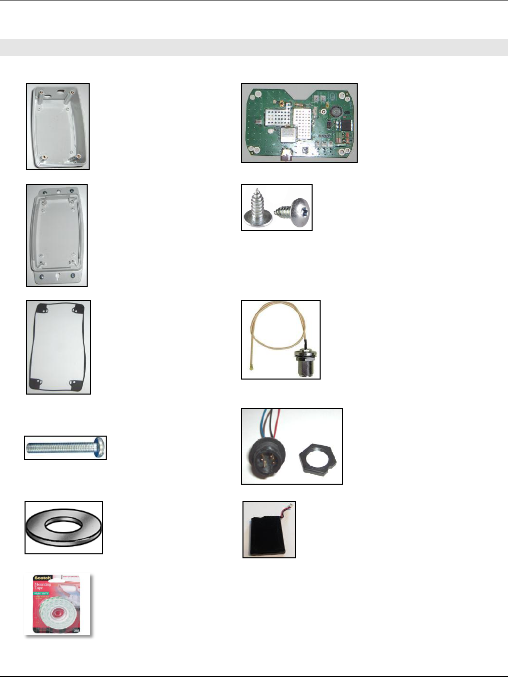
1. EQUIPMENT LIST
A. OREP Enclosure - Top (1)
B. OREP PCB (1)
C. OREP Enclosure - Bottom (1)
D. 1/4” Tapping Screws for PCB (4)
E. OREP Enclosure - Rubber Mat (1)
F. 8” Bulkhead to Pigtail RF Cable (1)
G. OREP Enclosure - Screws (4)
H. Inmate Male Panel Receptacle with Lead Wires (1)
I. OREP Spacer/Washer (4)
J. Tenergy Battery (1)
K. Double Sided Tape
OREP Assembly Manual 776-91-04-REV-A.docx
THE INFORMATION CONTAINED HEREIN IS PROPRIETARY TO NEW CENTURION SOLUTIONS, INC. AND SHALL NOT BE REPRODUCED OR
DISCLOSED IN WHOLE OR IN PART FOR ANY DESIGN OR MANUFACTURE EXCEPT WHEN SUCH USER POSSESSES DIRECT, WRITTEN
AUTHORIZATION FROM NEW CENTURION SOLUTIONS, INC.
5
2. ASSEMBLY INSTRUCTION
To begin, check the parts available against the equipment list, identifying any missing parts. If all
parts are accounted for, proceed to the instructions below to begin assembling the outdoor
repeater (OREP).
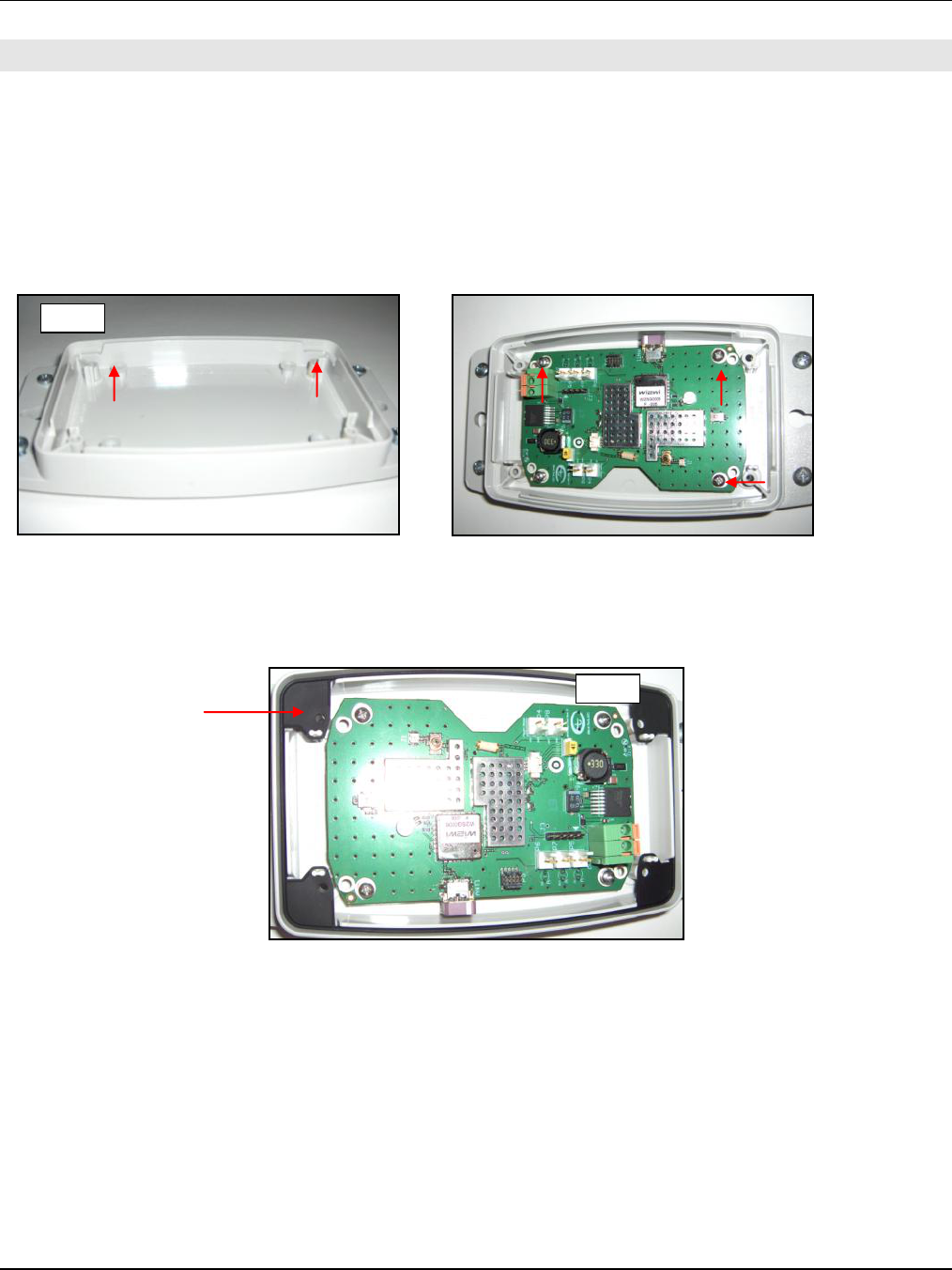
Step 1: Take the bottom enclosure (C) and place an OREP spacers/washers (I) over each of the
inside screw holes as designated in the figure below. Lay the OREP PCB (B) over the bottom
enclosure, making sure there is a spacer under each corner of the PCB. Insert a tapping screw (D)
into each corner, mounting the PCB to the enclosure.
Step 2: Identify the rubber mat and line the holes up with the elevated screw holes in each corner.
Feed the openings on the rubber mat through the double pegs beside each elevated screw hole.
Step 1
Step 2
OREP Assembly Manual 776-91-04-REV-A.docx
THE INFORMATION CONTAINED HEREIN IS PROPRIETARY TO NEW CENTURION SOLUTIONS, INC. AND SHALL NOT BE REPRODUCED OR
DISCLOSED IN WHOLE OR IN PART FOR ANY DESIGN OR MANUFACTURE EXCEPT WHEN SUCH USER POSSESSES DIRECT, WRITTEN
AUTHORIZATION FROM NEW CENTURION SOLUTIONS, INC.
6
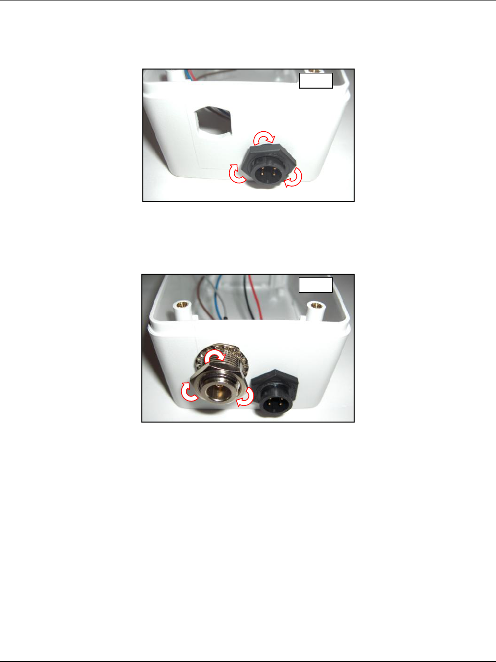
Step 3: Insert the panel receptacle (H) into the inside of the front enclosure with the pins facing
out. Rotate the nut (with the text facing outwards) clockwise around the receptacle until it is flush
against the bottom enclosure.
Step 4: Take the bulkhead RF cable (F) and remove the nut and washer. Insert the bulkhead into
the inside of the front enclosure with the pin facing out. Fasten the washer to the bulkhead
(outside of the enclosure) and rotate the nut clockwise until it is flush against the bottom
enclosure.
Step 3
Step 4

OREP Assembly Manual 776-91-04-REV-A.docx
THE INFORMATION CONTAINED HEREIN IS PROPRIETARY TO NEW CENTURION SOLUTIONS, INC. AND SHALL NOT BE REPRODUCED OR
DISCLOSED IN WHOLE OR IN PART FOR ANY DESIGN OR MANUFACTURE EXCEPT WHEN SUCH USER POSSESSES DIRECT, WRITTEN
AUTHORIZATION FROM NEW CENTURION SOLUTIONS, INC.
7
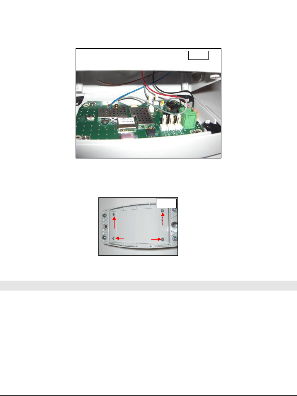
Step 5: Feed the wires from the panel receptacle into the terminal block labeled P1 on the PCB by
pushing down on one orange tab and feeding the wire through the respective terminal. Looking
down on the terminal block with the tabs on the right, the red wire should be inserted into the top
terminal and the black wire should be inserted into the bottom as indicated in the figure below.
Step 6: Insert the pigtail connector end of the RF cable into the RF port labeled J1 on the PCB by
laying connector over the port and pressing down on the connector. The connector should snap
right into place.
Step 7: Insert the Tenergy battery (J) connector into the 3 pin header on the PCB beside the “on”
switch. After doing so, apply a piece of double sided tape (K) to either side of the battery, and
press the battery against the metal shields on the PCB.
Step 5
Step 6
Step 7
OREP Assembly Manual 776-91-04-REV-A.docx
THE INFORMATION CONTAINED HEREIN IS PROPRIETARY TO NEW CENTURION SOLUTIONS, INC. AND SHALL NOT BE REPRODUCED OR
DISCLOSED IN WHOLE OR IN PART FOR ANY DESIGN OR MANUFACTURE EXCEPT WHEN SUCH USER POSSESSES DIRECT, WRITTEN
AUTHORIZATION FROM NEW CENTURION SOLUTIONS, INC.
8
Step 8: Lay one side of the top enclosure over the bottom enclosure, making sure that all of the
wires/cables are tucked inside and that none are folded over as that may cause damage. Slowly
close the enclosures together until the top enclosure is flush against the bottom. The edges should
fit together neatly.
Step 9: Flip the enclosures over so that the bottom enclosure is on top. Insert the 4 enclosure
screws (G) into the screw holes on the bottom enclosure. Screw clockwise to finish assembling the
OREP.
3. FCC NOTIFICATION
NOTE: THE MANUFACTURER IS NOT RESPONSIBLE FOR ANY RADIO OR TV INTERFERENCE
CAUSED BY UNAUTHORIZED MODIFICATIONS TO THIS EQUIPMENT. SUCH MODIFICATIONS
COULD VOID THE USER’S AUTHORITY TO OPERATE THE EQUIPMENT.
THIS DEVICE COMPLIES WITH PART 15 OF THE FCC RULES. OPERATION IS SUBJECT TO THE
FOLLOWING TWO CONDITIONS: (1) THIS DEVICE MAY NOT CAUSE HARMFUL INTERFERENCE, AND
(2) THIS DEVICE MUST ACCEPT ANY INTERFERENCE RECEIVED, INCLUDING INTERFERENCE THAT
MAY CAUSE UNDESIRED OPERATION.
Step 8
Step 9