New Force communication Technology NFC-9814 INTERROGATOR User Manual VM7NFC 9814 InstructionManual
Shenzhen New Force communication Technology Co.,Ltd INTERROGATOR VM7NFC 9814 InstructionManual
USERS MANUAL

Instruction of 9814 interrogator
Esteemed customers:
You are appreciated for your supports and trust. We will provide circumspect and all-sided
service and technology support with all our heart!
The instruction will detailedly tell you how to use the NFC-9814 interrogator, which is
researched and designed by ourselves. You are suggested to read the instruction detailedly before
using it so that you can taste the advantage and efficiency of our products.
If any comments and suggestions about our products in using, please don’t hesitate to contact
us, we shall service for you with all our heart!
The copyright of the instruction is owened to Shenzhen NFC communication Technology Co.,
Ltd. Not perrmits and authorization, please don’t tran-print, publish, diffuse or other use.

Instruction of 9814 interrogator
Instruction of 9814 interrgator
9814 interrogator is one of products researched and designed by Shenzhen NFC communication
and technology Co., Ltd. It has many perfect characteristices such as non-touching, not being effected
by environment, long-distance reading and writing, good capability of applying to object high
speed moving, convenient operating, anti-conflict and so on. It is very usefull far-ranging. At
present, NFC-9814 interrogator is applied to no stopping and charging fee management of high-
speed road(bridge), indentifying car’s brand management, car management of organizing into
groups and attempering, management of intelligent park, management of checking cars’
entering and leaving frontier, supervising material’s being out and in and identifying management,
baggage and package’s identifying management and containers on dock management and other
fields.
.
1、
summary
9814 is a kind of 915M RFID interrgator, which is full frame and function. It includes RF
module, digital signal managing, input/output port and serial communication port, synchronization
function.
9814 interrgator is multi-protocol UHF interrgator, which supports ISO18000-6B and EPC
potocol international standard, it can read and write UCODE, TI, Alian and othes label, besides it
can optimize main applying label clip. It is convenient to upgrade interrogator’s software to
satisfy protocol expanding and function expanding to protect user’s investment.
2、
Function
brief
introdution
z
Support multi-protocol: 9814 interrgator supports ISO18000-6B, EPC Class 1, EPC Class
1 GEN 2 standard, and also support many protocols and function expanding by through
upgrading interrogator software.
z
Label capability optimizing: NFC serial interrgators can optimize Label’s operating used
far-ranging. It uses different labels’ expanding function to enhance the price-quality ratio
of system’s applying.
z
Out off line function: the interrogator is designed with nonvolatile memory place. When
the interrogator fail to communicate with applying suetem, it can memory identified ID
Label into the interrgator to make sure the system is stable.
z
ID match function: the interrogator is designed with nonvolatile memory place. In a close
applying system, it can memory ID Label into the interrgator in advance. When the
interrogator indentifies Label ID, It can compare with the ID memoried the local PC,
then depending on the result, it can run the interrgator’s predefining or user
designing’action.
z
Synchronization function: In practice, many interrgators must be installed a near place, to
make sure the reliability when interrgators working, NFC serial interrgators were designed
especially with synchronization function to make sure the reliability of identifying
label

Instruction of 9814 interrogator
and reading rate.
z
Time function: There is real-time clock within interrgator, which can setup and read
interrgator’s time,identify time-stamp function under out off line. It can exactly satisfy the
applying design that uses were sensitive for time.
z
Input and output function: the interrgator is designed 2-way triggering input,
which can identify the label when occuring outer things to satisfy green environment
protecting and decrease energy consuming. It is especial suitable for parking
port and producing line manegement. It is designed 2-way relay output, which user
can use for outer controling so that saving user’s cost of applying system designed. User
can transfer and control relay’s switch status through the API function of NFC-interrgator
SDK and also can customize the controling relationship according to the number of
indentified Label ID.
z
Launching power separated control: can setup separated every channel’s launching power
to meet applying and installing’s complexity, which is the first designed and
created in internal country.
3、 Technology parameter
9814 interrgator technology parameter as belows:
Form 1 9814 interrgator’s technology parameter
Specification Explanation
Operating Frequency 902MHz~
928MHz
RF protocol ISO18000-6B、EPC Class 1、EPC Class 1 GEN 2
Operating Method fixed frequency
Antenna ports 4ports,SMA
Max RF power 1 mW(e.i.r.p)
Power smoothness <
0.5 DB
RF power range 0.5~1mW,
Adjustable by software
Identify tag mode
Fixed time automatically reads the tag;external trigger control
reads the tag or the software control reads the tag,Identify tag
mode can be setted
Identify tag time <8ms(Identify single tag)
Reading/Writing tag time Reads every 8 bytes to be smaller than 5ms,writes every 4
bytes to be smaller than 25ms
Reading/Writing tag distance >8m(antenna dependent)
Communication interface Type A:
RS-232、RS-485、Wiegand26/34 Type B:
RS-232、
RS-485、Wiegand、USB Type E:
RS-232、Wiegand、Ethernet
Input/output 2triggering inputs,2 relays outputs
Power supply DC 5V
Power consumption ≤5W
Size 200mm×190mm×80mm
Weight
Instruction of 9814 interrogator
Work Temperature -
10
℃
~+
55
℃
Storage Temperature -
20
℃
~+
85
℃
Work status indication Buzzer and LED
4、 Installing method and caution
The set of product includes one 9814 interrgator, one bar of RS232 serial port communicating
line, one +5V/1A power adapter and four tran-connecting lines. Please confirm if there are all
fittings in it when you opening the box, if any question, please contact our dealer quickly or
contact our after-sales Dept directly.
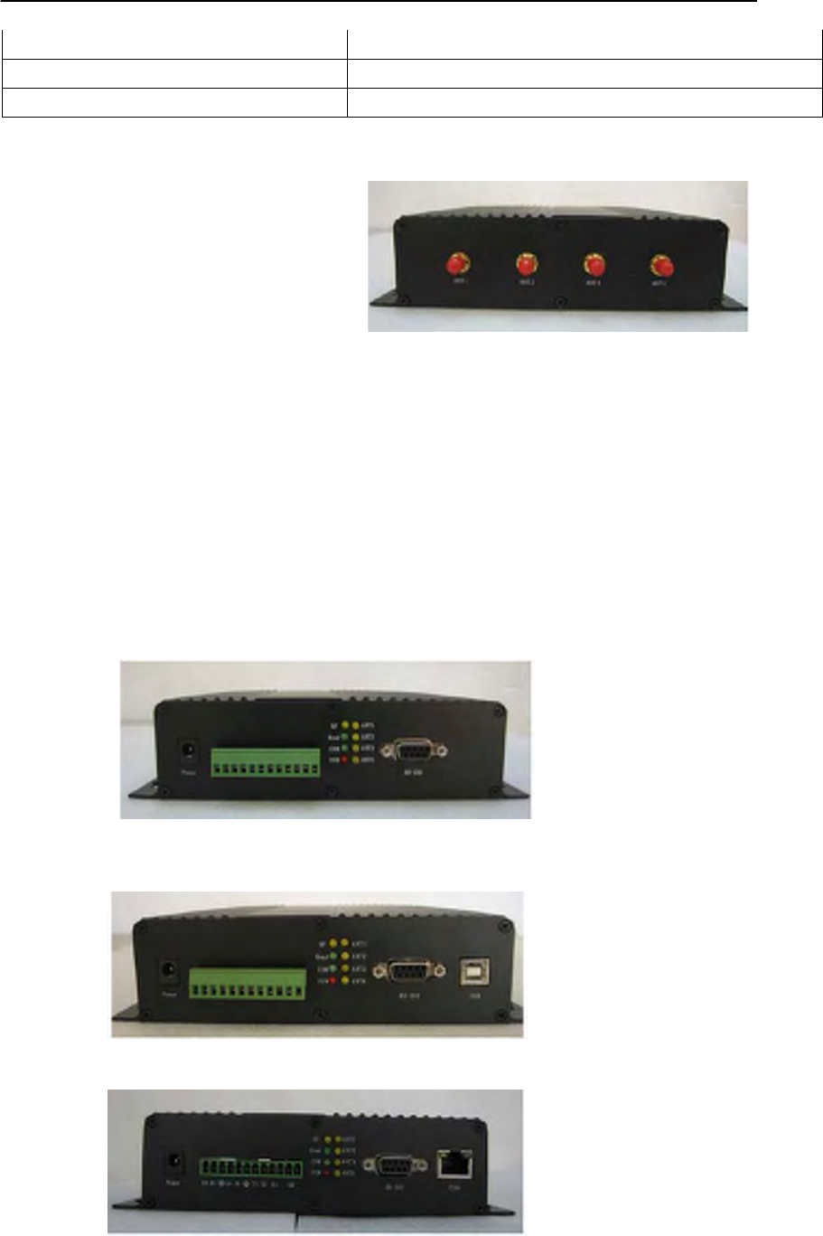
4.1 Apperance
The interrgator is black cuboid. One side of it is antenna channel port, oppositing it from
left there are direct power input port, serial communication interface, eight LEDs and RS232
port (9814A), USB port (9814B) and RJ poart (9814E) . There are screw holes to settle and
fasten the interrgator on its bottom.
Picture 2 9814A Interrogator
Picture 3 9814B Interrogator
Picture 4 9814E Interrogator
Num. Signal Name Function Direction
1
NC
2
RXD Reveiving data Input
3
TXD Sending data Output
4
NC
5
GND Ground
6
NC
7
NC
8
NC
9
+5V +5V power
supply
Instruction of 9814 interrogator
4.2 Port instruction and indicator light
1) DB9 socket is RS232 serial interface, details as follows:
Form 2 RS232 interface instrction
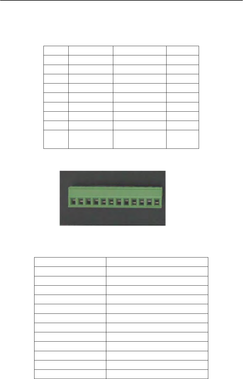
2)connecting line port from left to right as follows
Form 3 connecting line port
Picture 5 connecting line port
Signal Name Function
D0 Wiegand Data 0
D1 Wiegand Data 1
GND GND Line
A+ RS485 Data A+
B- RS485 Data B-
GND GND Line
T1 Triggering 1
T2 Triggering 2
K1 Relay 1 Port 1
K1 Relay 1 Port 2
K2 Relay 2 Port 1
K2 Relay 2 Port 2
3)We added eight LEDs as instructors when we designed, it isn’t only beautiful but also
convenient for user as he can know interrgator’s working status clearly. Every LED’s working
status as follows according to corresponding position:

Instruction of 9814 interrogator
“RF” shows interrgator is launching power
“READ” shows reading correct electronic label data
“COM” shows RS232 serial interface communication is formal
“POW” shows power supplying is formal
“ANT1” shows interrgator’s the first channel is connected to amtenna
“ANT2” shows the second channel of interrgator is connected to antenna
“ANT3” shows the third channel of interrgator is connected to antenna
“ANT4” shows the forth channel of interrgator id connected ot antenna
4.3 Install
The interrgator could be installed on woody, concrete, or bricky wall according antenna’s
position and user’s necessary, and it can also be put on plan object such as a desk.
5、Interrgator using instruction
5 5.1 Connect reliably on end of RS-232 serial line to the end COM1 of PC machine, connect
reliably the another end to serial interface of interrogator.
5. 5.2 voltage of alternating current power supplying of Power supplying adapter inputting end and
working frequecy according with the request: 100 V ~ 240 VAC/ 50 Hz, the outputting end is
inserted the hole of interrogator’s power source to supply power, and then the red LED light
is light, it shows that the system had been initialized and being waiting, if not, please check
the power source and interrgator.
After putting through interrogator, it is waiting. As thinking user’s requests, we had already
co configured basic parameter when it was produced to meet essential operating request. If not
co configured the parameter, please operate it as the fivth step. If you want to configured individuated
the the parameter, please observe the steps as follows.
5. 5.3 Open the procedure of configuring parameter on PC,chose the serial interface COM1 matched
w with serial interface of your PC: Baud rate is chosed and configured on pulling menu,station
st address is configured “arbitrary station”, then clik “connect ” button, watch the tputting signal
ou status. If it is shown “communication is normal”, it means that it is connected well between
w interrogator and PC; while if “communication abnormal” instand, it means that it isn't connected
well, please check interrogator and serial line.
5.4 5.4 Click the “querying parameter” button, you can watch the interrogator’a working status.
Par Parameter configuring has three modules including working way parameter, interrogator
and parameter and protocol parameter configuring. In these modules, it can be configured
w principal-subordinating working way, fixed time working way, or triggering working way; in
m interrogator parameter module, it can be configured power, antenna, reading card way and so on;
In protocol parameter, it can be configured support protocol and related parameter, more details
p please refer to the《NFC-9 serial interrogator ‘s instruction of parameter configuring procedure》
5.5 5.5 Open the interrogator demonstrating procedure on PC, chose the serial interface COM1

Instruction of 9814 interrogator
matched serial interface of your PC: Baud rate is chosed and configured on pulling menu, station
address is configured “arbitrary station”, then clik “connect” bottom and watch the outputting
signal status. If it is shown “communication is normal”, it means that it is connected well between
interrogator and PC; while if “communication abnormal” instand, it means that it isn’t connected
well, please check interrogator and rerial line.
5.6 In the interrogator demonstrating procedure, it can realize single card indentifying, multi-card
indentifying for different labels, reading module, writing module and LOCK operating and so on,
more details please refer to《NFC-9 serial interrogator Demo procedure instruction》
6、 Upgraded procedure instruction
Users are provided the upgraded procedure, which is a tool software to quick and brife update
interrogator’ fixing procedure . The software is the highest version as you first buy it, it cann’t be
provided with along our products. With the technology developing, we will update our products’
fixing procedure with new technology and provide it to users so that they can update and upgrade
quickly the NFC-9 serial interrogator’s internal procedure.
6.1 Open the upgraded procedure software on PC, chose the serial interface COM1 matched serial
interface of your PC: Baud rate is chosed and configured on pulling menu, station address is
configured “arbitrary station”, then clik “connect” button and watch the outputting signal status. If
it is shown “communication is normal”, it means that it is connected well between interrogator and
PC; while if “communication abnormal” instand, it means that it isn’t connected well, please check
the interrogator and serial line.
6.2 click the downloading button, the software can download the procedure into the interrogator,
progress bar shows working status. Appearring hint of upgrading finishing shows
downloading
is successful, more details please refer to 《 NFC-9 serial interrogator upgrading procedure
instrcution.
7、 Caution
7.1 As the interrogator module working(radiate microwave power), the guy
installed and adjusted must keep 30cm from antenna so that it can meet the request of America
FCC about the max RF items.
The instrction is just suitable for installing on the spot and adjusting the machine.
7.2 Please keep far away strong magnetic field when interrogator working.
8、 After-sale service
We will maintain free for you during one year depending on product’s number and
producing date. if any impacting, over-high Voltage, improper operating, opening the product by
youself, it isn’t our duty for your free maintaining.
If any comments and suggestions about our products in using, please don’t hesitate to contact
us, we shall service for you with all our heart!
If any technology question, please contact our technician anytime.

Instruction of 9 series interrogator
Esteemed customers:
You are appreciated for your supports and trust. We will provide circumspect and all-sided service
and technology support with all our heart!
The instruction will detailedly tell you how to use the DRF series interrogator demonstrating
procedure, which is researched and designed by ourselves. You are suggested to read the struction
detailedly before using it so that you can taste the advantage and efficiency of our products.
If any comments and suggestions about our products in using, please don’t hesitate to contact us,
we shall serve for you with all our heart!
Instruction of 9 series interrogator
Instruction of demonstration procedure
User can understand well 9 series interrogator’s function and capability through the demonstration
procedure exploited by ourselves.
You can understand our serial interrogators detailedly after you reading the instruction.
Prepareing working:
z
Before using the demonstrating procedure, you must copy the dish matched with the
interrogator to the designated path on you pc.
z
Correctly connect pc serial port and interrogator serial port
z
Connect interrogator power supplying, it is normal if the red light lights.
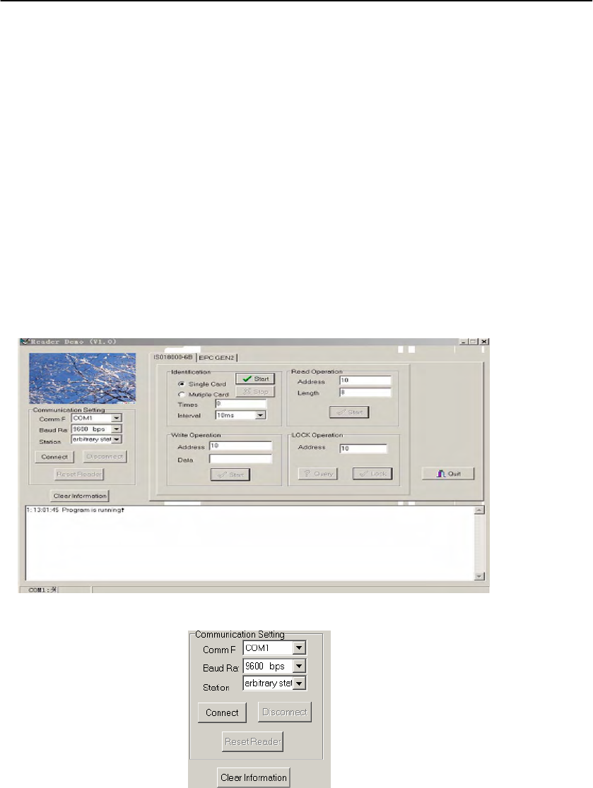
Running the demonstration procedure
In the directory path user named, doubble click “ReaderDemo.exe” ico.
Picture 1 the interface of interrogator demonstrating procedure
Picture 2 serial port configuring
Before user demonstrating, please correctly select serial port and configure BaudRate, then
click”connect”, if interrogator worked normally, the status column shows the machine and
communication are normal, then you can demonstrate the procedure.
ISO18000
function
domenstrating
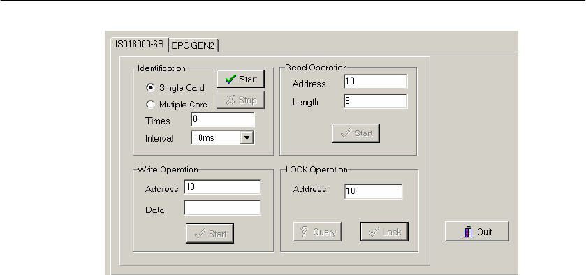
ISO18000 function demonstrating procedure can realize indentifying tag, readig tag, writing
tag, locking tag and querying block and so on.
Instruction of 9 series interrogator
Picture 4 ISO18000 function demonstrating interface
1、 ID indentification function
z
Single card indentifying: indentify single tag, you can select single tag indentifying when
there is only single tag under interrogator is efficient.
z
Multi-card indentifying: tag ID indentifying with anticollision arithmetic. Multi-tag can
be indentified under interrogator is efficient.
z
Readig times: times of single card or multi-card indentifying tag continued
z
Interval : interval of tag indentifying between two times identifying continued. The
interval is efficient when the reading times are bigger then 1, or configuring interval can
be neglected.
After configuring the request of tag indentifying function demontrating, click “start”button,
the result show on the frame.
2、 Reading tag
z
Reading address: reading the first byte address of tag memory, it is efficient from 0-255
z
Reading Length: reading byte length of tag memory.
After configuring the request of tag indentifying function demontrating, click “start”button, the
result show on the frame.
3、 Writing tag
z
Addr: write the address of tag memory, its efficient range 12-255
z
Data: write the data into tag memory
After configuring the request of tag indentifying function demontrating, click “start”button, the
result show on the frame.
4、 Locking tag and querying tag
z
LOCK Addr: Byte address of tag memory, its efficient range 12 ~255
After configuring LOCK address, click “query” button, query locking status for the
information of memory of tag designation, the result show on the frame.
After configuring LOCK address, click “Lock” button, lock the information of memory of
tag designation, the result show on the frame.
Instruction of 9 series interrogator
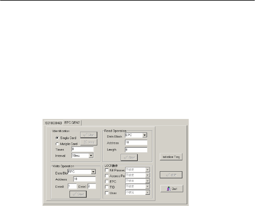
GEN2
function
demonstration
ISO18000 function demonstrating procedure can realize indentifying tag, readig tag, writing
tag, locking tag and querying block and so on. Picture 5 is the interface of i nterrogator GEN2
function domenstrating.
Please refer to the ISO18000 procedure instruction as the same as GEN2 about indentifying
lavbel, reading tag, writing tag. LOCK operating as follows:
Under lock operating, you can configure four ways such as destroying password, keeping and taking
password, EPC, TID and User not locking, forever not locking, opening status and
completely locking. You can select the information, then select corresponding operating on
pulling menu on the right.
Picture 5 the interface of GEN2 function demonstrating
Thechnology
support
You are appreciated for your comments and suggestions when you use the demonstration
procedure, we shall serve for you with all our heart!
If any question, please contact with our thecnician anytime!

ONLY MANUFACTURER CAN INSTALL ANTENNA(S) INTO THE SMA ANTENNA
PORTS (ANT1, ANT2, ANT3 AND ANT4) OF THIS DEVICE PERMANENTLY
WHEN PRODUCTION. THE USER CANNOT REMOVE FIXED ANTENNA FROM THE
DEVICE BECAUSE OF WELDING ANTENNA ON PORT(S). WE WILL PRODUCE
THE DEVICE WITH FOUR VERSIONS OF PRODUCTION:
1. THE VERSION 1 OF PRODUCTION – THE MANUFACTURER INSTALLS AN
ANTENNA INTO THE DEVICE WHEN PRODUCTION. THE OTHER THREE
PORTS WILL BE DISABLED OR BLOCKED FOR ANY TRANSMISSION BY
THE MCU OF THE DEVICE. FOR EXAMPLE, IF THE MANUFACTURER
INSTALLS AN ANTENNA INTO THE ANT2 PORT, OTHER THREE PORTS
(INCLUDE ANT1, ANT3 AND ANT4) WILL BE DISABLED OR BLOCKED BY
THE MCU OF THE DEVICE. IT MEANS ONLY ANT2 CAN TRANSMIT
SIGNAL OR FREQUENCY THRU THE ANTENNA WHICH IS CONNECTED IN
THE ANT2 PORT.
2. THE VERSION 2 OF PRODUCTION – THE MANUFACTURER INSTALLS TWO
ANTENNAS INTO THE DEVICE WHEN PRODUCTION. THE OTHER TWO
PORTS WILL BE DISABLED OR BLOCKED FOR ANY TRANSMISSION BY
THE MCU OF THE DEVICE. FOR EXAMPLE, IF THE MANUFACTURER
INSTALLS ANTENNAS INTO THE ANT2 PORT AND ANT3 PORT, OTHER
TWO PORTS (INCLUDE ANT1 AND ANT4) WILL BE DISABLED OR
BLOCKED BY THE MCU OF THE DEVICE. IT MEANS ANT2 AND ANT3 CAN
TRANSMIT SIGNAL OR FREQUENCY THRU THE ANTENNAS WHICH ARE
CONNECTED IN THE ANT2 PORT AND ANT3 PORT.
3. THE VERSION 3 OF PRODUCTION – THE MANUFACTURER INSTALLS
THREE ANTENNAS INTO THE DEVICE WHEN PRODUCTION. THE OTHER
PORT WILL BE DISABLED OR BLOCKED FOR ANY TRANSMISSION BY THE
MCU OF THE DEVICE. FOR EXAMPLE, IF THE MANUFACTURER INSTALLS
ANTENNAS INTO THE ANT2 PORT, ANT3 PORT, ANT4 PORT, THE OTHER
PORT (i.e. ANT1) WILL BE DISABLED OR BLOCKED BY THE MCU OF
THE DEVICE. IT MEANS ANT2, ANT3 AND ANT4 CAN TRANSMIT SIGNAL
OR FREQUENCY THRU THE ANTENNAS WHICH ARE CONNECTED IN THE
ANT2 PORT, ANT3 PORT AND ANT4 PORT.
4. THE VERSION 4 OF PRODUCTION – THE MANUFACTURER INSTALLS FOUR
ANTENNAS INTO THE DEVICE WHEN PRODUCTION. FOR EXAMPLE, IF
THE MANUFACTURER INSTALLS FOUR ANTENNAS INTO THE ANT1 PORT,
ANT2 PORT, ANT3 PORT AND ANT4 PORT. IT MEANS FOUR ANTENNAS
CAN TRANSMIT SIGNAL OR FREQUENCY THRU THE ANTENNAS WHICH IS
CONNECTED IN THE ANT1 PORT, ANT2 PORT, ANT3 PORT AND ANT4
PORT.
THE MANUFACTURER IS NOT RESPONSIBLE FOR ANY RADIO OR TV
INTERFACE CAUSED BY UNAUTHORIZED INSTALLATION OF ANTENNA INTO
THIS EQUIPMENT. SUCH UNAUTHORIZED INSTALLATION COULD VOID THE
USER’S AUTHORITY TO OPERATE THE EQUIPMENT.
FCC NOTE
THE MANUFACTURER IS NOT RESPONSIBLE FOR ANY RADIO OR TV
INTERFERENCE CAUSED BY UNAUTHORIZED MODIFICATIONS TO THIS
EQUIPMENT. SUCH MODIFICATIONS COULD VOID THE USER’S AUTHORITY
TO OPERATE THE EQUIPMENT.