Newcon Optik Lrf Mod 4Ec Users Manual
LRF MOD 4EC to the manual 51edf42e-432d-4765-9712-6bc96f2d2627
2015-02-02
: Newcon-Optik Newcon-Optik-Lrf-Mod-4Ec-Users-Manual-439142 newcon-optik-lrf-mod-4ec-users-manual-439142 newcon-optik pdf
Open the PDF directly: View PDF ![]() .
.
Page Count: 40
Operation Manual
LASER RANGE FINDER MODULE
LRF MOD 4EC
105 Sparks Ave., Toronto, ON, M2H 2S5, Canada

ii

iii
IMPORTANT INFORMATION
Read prior to activation
You have just purchased a sophisticated electro-optical device
that emits invisible laser radiation. To operate it properly, please
read this manual carefully.
• NEVER direct laser beam at the eyes of people or animals
• NEVER aim the unit at the Sun or bright sources of light
• NEVER subject the unit to impacts
• NEVER transport the unit without its case
• NEVER disassemble the unit. This may be hazardous for you
due to high voltage currents in the system
• ALWAYS keep the unit out of children’s reach
• ALWAYS store the unit in a dry place
• Caution - use of controls or adjustments, or performance of
procedures other than those specified herein may result in
hazardous radiation exposure
• Caution - use of optical instruments such as binoculars, loupes,
mirrors, lenses, etc. with this product increases eye hazard.
• Caution - avoid access of direct sun light into eye-piece optics
for more then 5 sec consistently.
• Note: Avoid eye exposure to direct laser beam or its close
reflection

1
CONTENTS
1. BRIEF DESCRIPTION............................................ 3
1.1 Principle of work ................................................. 4
1.2 Key Features ........................................................ 4
2. DEVICE APPEARANCE ........................................ 5
3. DELIVERY SET ...................................................... 7
3.1 Standard delivery set............................................ 7
3.2 Optional accessories ............................................ 7
4. SPECIFICATIONS .................................................. 8
5. OPERATION INSTRUCTIONS............................ 10
5.1 Maximum distance............................................. 10
5.2 Module controls ................................................. 10
5.3 Measurement procedure..................................... 11
5.4 Target selection logic......................................... 12
5.5 Individual Measurement and Scanning regimes 12
5.6 Operation and service modes............................. 13
5.7 Mode switching and tuning................................ 14
5.8 Setup mode ........................................................ 16
5.9 Compass calibration........................................... 19
5.10 Interface format ................................................. 19
5.11 Gating mode....................................................... 20
5.12 Data Recall mode............................................... 21
5.13 Display test mode .............................................. 22

2
5.14 Additional display information.......................... 22
6. BEST MEASURING TECHNIQUE...................... 23
7. Interconnectivity..................................................... 25
7.1 Connecting to computer..................................... 25
7.2 Data output protocol .......................................... 25
7.3 Additional communication features, for special
orders only ..................................................................... 27
7.4 Output connector pin layout and cable diagram 29
7.5 GPS interconnectivity ........................................ 30
8. STORAGE AND MAINTENANCE...................... 32
9. TROUBLESHOOTING ......................................... 33
10. WARRANTY......................................................... 34
11. CUSTOMER SUPPORT........................................ 35
12. QUALITY CERTIFICATE.................................... 36

3
CAREFULLY READ ALL THE INSTRUCTIONS
BEFORE USING!
FAILURE TO OBEY THE INSTRUCTIONS WILL
VOID THE WARRANTY AND MAY CAUSE
INJURY!
1. BRIEF DESCRIPTION
The LRF Modules use the same electronics and optics as
rangefinder monoculars and binoculars. These modules can add
various range finding capabilities into host systems: distance &
speed measurement, azimuth and elevation measurement.
The modules have a built-in computer interface, which enables
immediate data acquisition by any system with standard serial
interface. Depending on exact model, customer has a choice of
various incorporated features, including, but not limited to gating
capability, fast scan mode, speed measurement, object selection
and more.
Typically a rangefinder module becomes a part of:
- Thermal imagers
- Day/night surveillance systems
- Airborne optical systems.
Both modules can be integrated into a bigger observation system.
The Modules comply with CFR 21, Part 1040.10

4
Principle of work
The Modules send invisible, eye safe laser pulses to the target.
Pulses reflected from the target are captured and processed by the
digital circuitry. The time-of-flight delay between the sent and
received pulses allows calculating the distance to the target.
A built-in digital compass/inclinometer of MOD 4EC measures
target’s azimuth and elevation simultaneously with ranging.
Key Features
Selection of the first, last or the most reflective target
Distance is displayed in meters or yards, speed is displayed
in km/h or MPH, azimuth and elevation are displayed in
degrees or mils
Original digital circuitry allows ranging through most types
of glass, bushes and other obstacles
Two reticle shapes: -¦- or □
Built-in digital accurate compass/inclinometer, angles are
displayed in degrees or mils.
On-board memory keeps results of the last 10 measurements,
that can be recalled
5
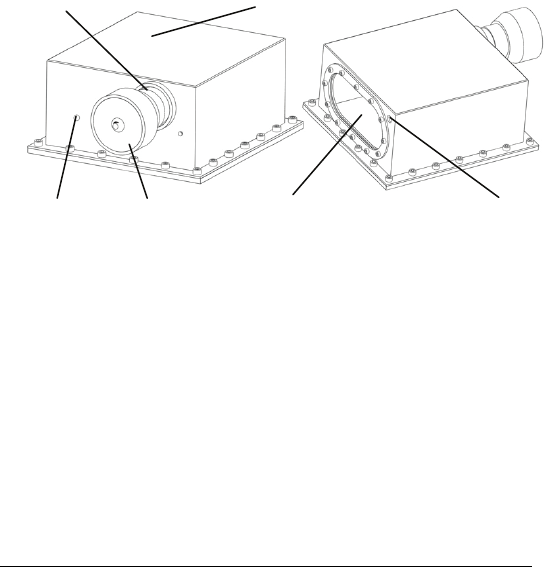
2. DEVICE APPEARANCE
1 – Communication connector 2 – Detachable eye-piece
3 – LRF cover 4 – Desiccator
5 – Optical window 6 – Detachable camera
5
3
1
2
Fig. 1. MOD 4EC general view
4
6
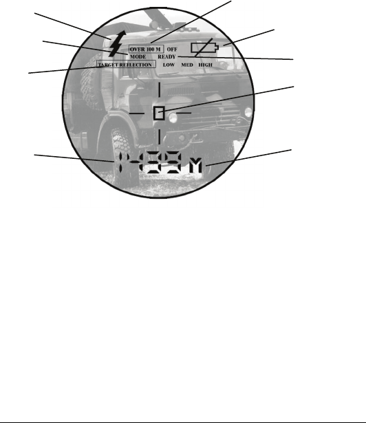
6
1 – Low battery indicator 2 – Reticle (either -¦- or )
3 – Units of measurement 4 – Measurement result
5 – Target quality indicator 6 – Laser active indicator
7 – Gating indicator 8 – Setup mode indicator
9 – Ready mode indicator
Fig. 2. Liquid Crystal Display view
through the eyepiece
4
6
2
7
1
5
3
9
8

7
3. DELIVERY SET
Standard delivery set
The unit is supplied in the following assembly:
Qty
LRF MOD 4EC 1
Eyepiece 1
USB camera 1
Compact disk with software 1
Computer/power cable 1
Operation manual 1
Warranty card 1
Hard case 1
Connectors:
Data/power connector LEMO Push-Pull Connector
FGG.0B.309.CLAD52
Data and power connectors can be modified per individual
order.
Optional accessories
GPS cable
Remote control module

8
4. SPECIFICATIONS
Range Finder
Laser
Measuring range
Accuracy
First, last and auto target selection
Meters/Yards display
Last 10 readings recall
Reticle
Target quality indicator
Class 1, eye safe, 905 nm
16 m – 4,000 m
± 1 m
Yes
Yes
Yes
-¦- or
Yes
Gating capability, m 100 - 7,000; 100 m step
Speed measurement
Measured speed range 5 – 400 km/h / 3-250 mph
Accuracy, km/h or mph ±2
Compass and inclinometer (MOD 4EC only)
Measured azimuth range 360°
Accuracy ±1°
Measured elevation range ±60°

9
Interface
RS 232 interface.
Power
External power requirement 9V DC, 300 mA
The unit is fully operational when voltage is higher than 7V. A
‘LOW BATTERY’ warning is displayed when voltage falls
below 7.2V.
Environmental
Operational temperature range
Storage temperature range
-25 / +50ºC (-13 / +122ºF)
-45 / +65ºC (-49 / +149ºF)
Mechanics
Weight without eyepiece
Weight with eyepiece
Dimensions without eyepiece
Dimensions with eyepiece
2,370 g
2,450 g
214x195x94 mm
238x195x94 mm

10
5. OPERATION INSTRUCTIONS
Maximum distance
Though maximum measurement distance depends on target
reflectivity, weather conditions and other conditions, for most
targets the unit will provide accurate ranging for up to 3,000
meters. In good conditions a highly reflective target can be
measured up to 4,000 meters.
Target reflectivity depends on its color, surface finish, size,
shape, position in relation to the laser beam, etc. Bright target
colors are more reflective than dark ones. A polished surface is
more reflective than a rough one. Larger targets reflect better
than small ones. Ranging a target perpendicular to the laser beam
provides better results than the one positioned under a sharp
angle to the beam.
Weather conditions that influence air transparency (rain, fog,
snow, mist) reduce maximum range. Bright sunny days will
reduce performance as well, as IR sun radiation may cover
reflected laser pulses.
While the unit will measure through many glass types, measuring
through glass may reduce accuracy and range.
Module controls
Modules can be fully controlled via RS-232 connector and/or
with buttons on remote control. The control procedures are
identical and interchangeable.

11
The correspondence between the pressing of the buttons and the
signals sent via RS-232 is described in Interconnectivity, chapter
7.
The rest of this manual describes measurement procedures and
setting measurement parameters through pressing of the buttons.
Measurement procedure
When the Module is off the LCD is blank. To activate it press
and hold for one second the Action (A) button. At start the
module comes into the Ready to Measure mode indicated by the
word ‘READY’ on the display.
Pressing the Action button in the Ready to Measure mode
initiates measurement. The result of the measurement is
displayed in a form that depends on the measurement parameters
(see Setup Mode).
Note:
If more than one parameter is chosen to measure, e.g.
distance and azimuth, the results will replace each other on
the display every half a second.
If the target is located below the unit the result of vertical
measurement (elevation or height) will be preceded with
minus (“-“) sign.
If results of angular measurements can not be interpreted by
the unit an error codes 444 (for azimuth) or 99 (for
elevation) will be displayed. Repeat the measurement. If
error codes appear again – reboot the unit by switching it off
and on again.

12
Target selection logic
On its way towards the target, laser beam may reflect from
various objects, thus decreasing ranging accuracy. The smaller,
the farther, and the less reflective is the target – the higher is the
possibility of obtaining an incorrect measurement.
To improve accuracy the unit has a built-in target selection logic,
which allows choosing what target to range: the nearest (‘first’),
the farthest (‘last’), or the most reflective (‘auto’).
This mechanism helps selecting the target when ranging from
behind the bushes, wires, through the falling snow, or in similar
conditions. Similarly it enables ranging a target in front of a
bigger object, such as a wire in front of the wall.
Note: Even with target selection logic the unit may not always be
able to range the desired target as its reflectivity may be too low
to produce enough laser beam reflections for statistically reliable
calculation. A warning will be displayed if result is not
statistically reliable. See more about target reflectivity in
Additional display information (0). This information will not be
transferred via RS-232.
Individual Measurement and Scanning regimes
The unit can operate in two regimes: (1) Individual Measurement
and (2) Scanning. In the Individual Measurement regime the unit
performs single measurement when the A button is pressed
shortly, in the Scanning regime the unit repeatedly measures and
displays results every second while the A button is pressed.

13
To activate the Scanning regime press and hold the A button in
Ready mode. The unit will work in the Scanning regime while
the A button is pressed.
Scanning or Individual Measurement regimes are available for
any selected mode of measurement. When two parameters are
measured in the Scanning regime though both will be quickly
displayed, the second one may be difficult to register by eye.
Nevertheless all data is recorded and may be recalled (see Data
Recall mode for details.)
Operation and service modes
The unit has the following modes of operation:
Ready to Measure – to perform measurements
(Quick link to the Standard1 and Standard2 sets of
measurement parameters appears in mode selection
menu for convenience and does not constitute a separate
mode)
Setup – to modify the Ready to Measure mode parameters,
Gating – to set a minimum distance of measurement,
Data Recall – to recall the last 10 measurement results,
Data Clearance – to clear measurement results.
In the Setup mode four parameters of measurement can be set;
these parameters define:
1. What the unit measures: distance or azimuth or elevation or
all measurements at once,

14
2. In what units result of distance measurement is displayed:
meters or yards, degrees or mils, km/h or mph,
3. What reticle shape is visible: rectangular or crosshair, and
4. Which target is selected: first, last or most reflective (see the
Target selection logic (5.4) for more details).
The Setup mode is described in more detail below.
The unit has two standard sets of the Ready to Measure mode
parameters:
Standard1: distance is displayed in meters, azimuth and
elevation are displayed in degrees, crosshair reticle is
visible, auto target selection is used,
Standard2: distance is displayed in meters, azimuth and
elevation are displayed in mils, crosshair reticle is visible,
auto target selection is used,
Code 8 sets the same set of measurement parameters as the
Standard1, except for distance measurement in yards.
At start the unit assumes the Ready to Measure mode with
measurement parameters inherited from the previous setup. At
manufacturing stage the unit is set up into Standard1 set of
measuring parameters.
Mode switching and tuning
Pressing the Mode (M) button in the Ready to Measure mode
switches the unit between modes of operation:
Ready to Measure – Ready (9, Fig. 2) is displayed

15
Quick link to the Standard1 set of measurement parameters
(display name: Std1),
Quick link to Standard2 set of measurement parameters
(display name: Std2),
Setup mode (display name: COdE),
Gating mode (display name: GAt),
Data Recall mode (display name: rEc),
Memory Clearance mode (display name: cLr),
Interface selection mode (display name: -PC- or
PLGr).
Flashing display name indicates the mode which can be selected
by pressing the A button.
The Setup, Gating selection, Data Recall and Interface selection
modes have submenus, so when the A button is pressed to select
these modes the unit automatically enters the corresponding
submenu. In the same way as with the mode switching, the M
button switches between the submenu items and A selects the
needed one. When the A button is pressed from the submenu the
unit comes into the Ready to Measure mode with the selected
parameter.
If no button is pressed for 8 seconds the unit leaves the current
mode, in the Ready mode it switches off. Next time the unit is
turned on it assumes the last chosen combination of the four
Ready to Measure mode parameters.

16
Note: On a special request a menu of a particular unit can be
simplified to show only required modes.
Setup mode
To modify the Ready to Measure mode parameters:
Enter the Setup mode.
With word Ready on the display press the M button till
display name COdE is displayed and press the A button.
Select the desired parameter modification (see table below).
Press the M button till the code name of the desired
parameter is displayed and press A button.
To leave the Setup mode without changing measurement
parameters press and hold the M button for two seconds. This
works like the computer Esc key. The rangefinder will then keep
the last set of parameters and return to the Ready to Measure
mode.
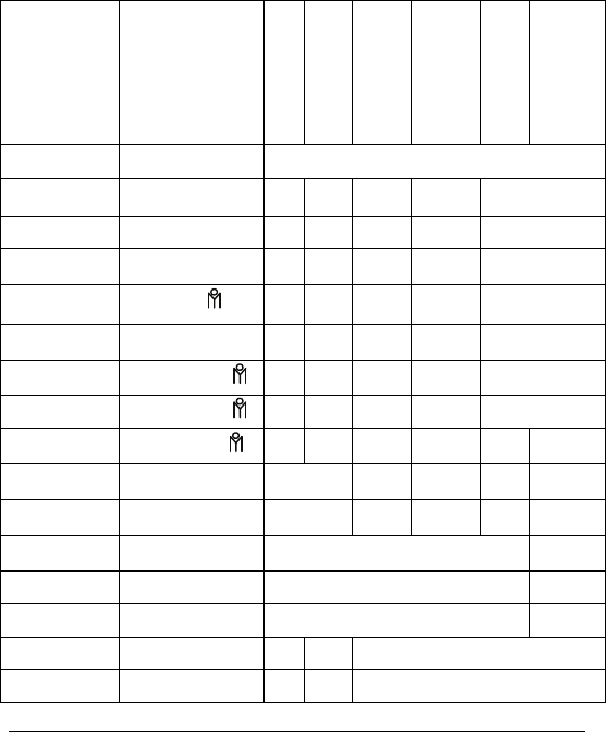
Mode
Display name
Distance
Speed
Azimuth
Elevation
Reticle
Target
selection logic
Ready to
Measure Ready As set at previous session
Standard1 Std 1 m Deg Deg -¦- Auto
Standard2 Std 2 m Mils Mils -¦- Auto
17
Mode
Display name
Distance
Speed
Azimuth
Elevation
Reticle
Target
selection logic
Setup COdE Entrance into the Setup mode
Cd1 M m NC
Cd2 Y yd NC
Cd3 - ◦ Deg NC
Cd4 - Mils NC
Cd5 - ◦ Deg NC
Cd6 - Mils NC
Cd7 - m NC
Cd8 - yd Deg Deg -¦- Auto
Cd9 -¦- NC -¦-
NC
Cd 10 NC NC
Cd 11 NC Last
Cd 12 NC First
Cd 13 NC Auto
Cd 14KMH NC kmh NC
Cd 15MPH NC mph NC

18
Mode
Display name
Distance
Speed
Azimuth
Elevation
Reticle
Target
selection logic
Cd 16 Display test
Cd 17 Compass calibration
Gating GAt Entrance into gating mode
Data
Recall rEc Recalls last 10 measurement sets
Data
Clearance cLr Clears all recorded data
Interface
format
-PC- or
PLGr Selects PC or PLGR data format for output port
Empty field means the parameter is not measured in this mode, NC
means ‘no change’ to the measurement parameter setting.
Once set, the mode parameter is stored in on-board memory and
will be kept current until reset in the Setup mode.
Choosing Cd 16 in the Setup mode will cause all display
segments and indicators to flash for 8 seconds. Flashing can be
interrupted by pressing either button.

19
Compass calibration
If the Module was exposed to a strong magnetic field or was not
in use for a long time, the compass accuracy may diminish.
To bring the compass into working condition:
Select Cd 17 in the Setup mode
Keeping the unit horizontally, perform one full rotation
around vertical axis within half a minute and then one full
rotation around vertical axis with device upside down
during half a minute.
If one rotation does not restore calibration – perform two
rotations.
The normal compass functioning will be restored.
Depending on the version of the on-board software, during
calibration LCD will show either time countdown in seconds
from 59 to 1 or flashing word CAL.
To ensure azimuth measurement accuracy calibrate compass
after changing the battery.
Interface format
The unit can output measurement data via RS-232 port in either a
proprietary protocol or in the format accepted by PLGF/DALGR.
The selected format will be indicated on the LCD with display
names PLGr or -PC-.
To select the required data transfer format:
Select PLGr (-PC-) in the Setup mode

20
Pressing the A button will activate shown on the LCD
communication format.
Gating mode
In this mode the gating function is activated: user can set the
minimal distance to the target; reflection from any object closer
than the gating distance will be ignored.
The Gating feature helps measuring remote targets in adverse
atmospheric and environmental conditions by eliminating
reflections from snowflakes, raindrops, industrial wires,
branches, etc. At the same time, if gating distance is set
incorrectly, you can remove the desirable object from
measurement range.
To enter the gating mode press the A button when GAt is
displayed. Minimal gating distance of 100 m will be initially set,
further pressing the M button will increase gating distance by
100 m up to 7,000 m. When the desired distance is reached –
select it by pressing A button.
The Gating distance can potentially be set longer than the
maximum measuring range. The device will not measure
anything then. To deactivate gating choose one of preset modes
that do not include gating (for example: Standard1, Standard2,
Code1, Code2, etc.).
Note: the Gating distance can only be increased. To exit gating
selection cycle without setting any gating distance press the M
button 70 times or hold the M button for 2 seconds.

21
Data Recall mode
In the Data Recall mode results of the last 10 measurements can
be displayed.
Measurement results are saved in on-board memory in sets
depending on the parameters set for measuring, for instance, if
only distance is measured - the set will consist of one number, if
distance and azimuth are measured – the set will consist of two
numbers.
To enter the Data Recall mode press the M button in the Ready
to Measure mode until rEc is displayed and then press the A
button. First measurement set number (display name: rEc 1)
will start flashing.
Pressing the M button moves the unit along the list of
measurement set numbers and measurement results:
rEc 1, distance 1, azimuth 1, elevation 1,
rEc 2, distance 2, azimuth 2, elevation 1, …,
rEc 0, distance 0, azimuth 0, elevation 0.
Measurement sets are numbered in reverse order: first recalled
set is the result of the last measurement. If any parameter has not
been actually measured it will not be recalled.
Pressing the A button at any moment within the list of recalled
results (or pressing the M button at the end of the list) brings the
unit to the Ready to Measure mode.
Choosing cLr in the Setup mode will erase all measurement
data.

22
Display test mode
Selecting Code 16 in the Setup mode will cause all display
segments and indicators to flash for 8 seconds.
Additional display information
Additional indication is displayed in the Ready to Measure
mode:
Y or M Indicates that distance is measured and
displayed in yards or meters
KMH or
MPH
Indicates that speed is measured and displayed
in km/h or mph
° Indicates that only azimuth is measured
° Indicates height in meters or azimuth is mils
measured
OVER 100M – indicates that gating is active
Laser active indicator (6, Fig.2) flashes, when unit emits laser
radiation. Reliability of ranging depends on the number of pulses
that reflect from the target and reach the unit. Module informs
user about the number of received pulses by a message on LCD:
TARGET REFLECTION LOW – ranging results have low
statistical reliability,
TARGET REFLECTION MED – ranging results have
medium statistical reliability,
TARGET REFLECTION HIGH – ranging results have high
statistical reliability.

23
6. BEST MEASURING TECHNIQUE
Laser range finder module measures distance by catching a laser
beam reflected from the target. Everything that improves
reflection increases the measurement reliability and maximum
range.
1. Aim at a surface on the target that is closest to the
perpendicular to the laser beam. The closer you get – the
stronger will be the reflection.
2. The unit deploys sophisticated software that tries to
understand which target you are aiming at. However, due to
beam divergence several objects may produce a strong
reflection. To help the system recognise the target the Target
Selection Logic may be used. For example, if ranging a wire
in front of a building, selecting the “first” target (Code 12)
will produce a more reliable result. Alternatively, when
aiming at a chimney behind the trees, selecting “last” target
(Code 11) will be better. By default the System assumes
“auto” target selection, that is, the object producing the most
reflections will be considered a target.
3. Another way to improve reliability of measurement is to use
the gating mechanism. When gating is active reflections
from all objects closer than the gating distance will be
ignored. This is especially effective when ranging in
unfavourable atmospheric conditions, that is, in the rain, fog,
haze or bright sun. Gating provides better results than the
“last” target selection, but it requires preliminary rough

24
distance estimation to cut off all objects closer than the
chosen one.
Note: the Gating setting is remembered by the System until
altered. Therefore, if you forget to turn the gating off, the next
time you start measuring it can ignore the desired object, if it is
closer than the gating distance. The unit will display four dashes
instead of the measurement results. “Over 100 meters” display
indicator shows active gating.

25
7. Interconnectivity
The unit supports RS-232 interface. Physical connection is
performed through a connector specific to each order. The
default connectors are described in Specifications.
Connecting to computer
The communication port must be initiated prior to connecting the
unit.
Data is transmitted as a hex string code with fixed baud rate of
9600 bit/sec, 8 bits, one stop bit, and no parity.
If the port is connected and not initiated, the module will be
activated immediately in scan mode.
Data output protocol
This physical interface uses one line to an external UART
(Universal Asynchronous Receiver / Transmitter) port. The data
is transferred in accordance with the serial asynchronous
communications protocol, known as the RS-232.
A typical UART frame is shown below. It comprises a Start bit, 8
data bits, and a Stop bit.
Along with the data transfer line the RS-232 port includes signal
lines, used to control the module.
UART Frame
Start
D0
D1
D2
D3
D4
D5
D6
D7
Stop
Start
D0
D1

26
The data string has the following structure (in Hex):
b1 b2 b3 E4h b5 E4h 0Dh 0Ah,
where:
b1 – type of measurement;
b2 – sign of measurement (1 – minus, 2 – plus);
b3 – LSB of result;
b5 – MSB of result
Result of measurement = MSB * 256 + LSB
In both standard modes, when three parameters are measured, the
module will generate three data sequences in one block, where
the first one presents results of distance measurement, the second
– results of azimuth measurement, the third – result of inclination
measurement.
The data string will look like:
b1 b2 b3 E4h b5 E4h
b7 b8 b9 E4h b11 E4h
b13 b14 b15 E4h b17 E4h 0Dh 0Ah
Where bytes contain the following information:
b1, b7, b13 – type of measurement
b2, b8, b14 – sign of measurement (1 – minus, 2 – plus)
b3 – LSB of the result for the first type of measurement
b5 – MSB of the result for the first type of measurement
b9 – LSB of the result for the second type of measurement

27
b11 – MSB of the result for the second type of measurement
b15 – LSB of the result for the third type of measurement
b17 – MSB of the result for the third type of measurement
Marker E4h is used to separate numbers, 0Dh 0Ah – to separate
data sets.
Type of measurement (bytes b1, b7, b13) can have the following
value:
1 – Distance in meters
2 – Distance in yards
3 – Azimuth in degrees
4 – Azimuth in mils
5 – Elevation in degrees
6 – Elevation in mils
7 – Elevation in meters
8 – Speed in km/h
9 – Speed in MPH
Additional communication features, for special
orders only
Module sends its menu status to the interface every time the
“Mode” button is pressed.
The mode state string has the following structure (in Hex):
S1 S2 S3 S4 0Dh 0Ah,
where

28
S1 – first symbol of the status menu
S2 – second symbol of the status menu
S3 – third symbol of the status menu or 21h
S4 – 21h or 00h
Examples of the LRF menu output:
Output, Hex Output, ASCII LRF menu
position
53h 54h 31h 21h
0Ah 0Dh
ST1! <LF><CR> Standard 1
43h 4Fh 44h 21h
0Ah 0Dh
COD! <LF><CR> Code
47h 41h 54h 21h
0Ah 0Dh
GAT! <LF><CR> Gating
52h 45h 43h 21h
0Ah 0Dh
REC! <LF><CR> Recall
43h 4Ch 52h 21h
0Ah 0Dh
CLR! <LF><CR> Clear
52h 44h 59h 21h
0Ah 0Dh
RDY! <LF><CR> Position
Ready
43h 31h 21h 00h
0Ah 0Dh
C1!
<NUL><LF><CR>
Code 1
47h 31h 21h 00h
0Ah 0Dh
G1!
<NUL><LF><CR>
Gating over
100 m

29
Output, Hex Output, ASCII LRF menu
position
43h 31h 32h 21h
0Ah 0Dh
C12! <LF><CR> Code 12
47h 32h 34h 21h
0Ah 0Dh
G24! <LF><CR> Gating over
2400 m
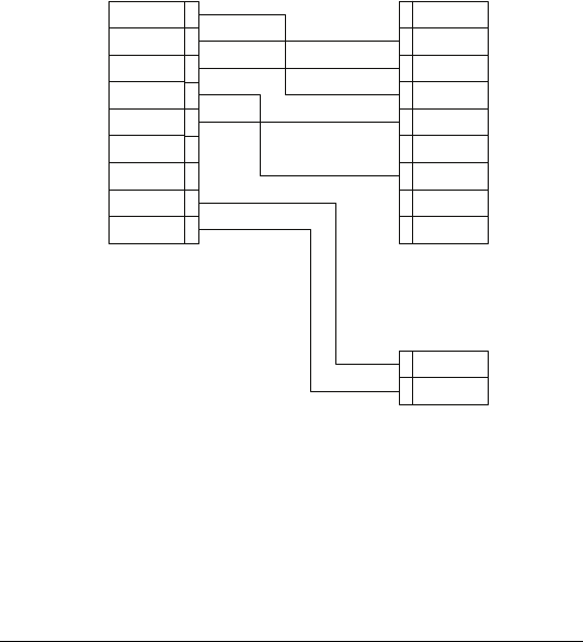
Output connector pin layout and cable diagram
By default for the output connector the module uses the
connector as described in Specifications. This connector
withstands high environmental loads and is designed for outdoor
usage.
30
Figure 4. Cable diagram
Connector and cable layout can be modified for specific
customer needs.
GPS interconnectivity
The Modules can transmit the acquired data to a GPS receiver
using the same output connector and the PLGR/DAGR protocol.

31
Another cable is required and can be supplied as an option.
To work with GPS, perform the following steps:
Switch to PLGr mode;
Choose either Std1 or Std2 measuring mode;
Connect the unit to and the GPS unit with the cable.
For each measurement the GPS unit will display the absolute
coordinates of your target.
Note: If the module is not set initially to the Std1or Std2 modes,
GPS connection will not operate properly.
Note: The GPS unit automatically adjusts coordinates to reflect
actual magnetic declination. Therefore, coordinates
displayed on the GPS may differ from those calculated by
the computer.

32
8. STORAGE AND MAINTENANCE
The unit is a sophisticated precision optical instrument equipped
with laser and electronics. Therefore, it should be handled with
due care.
• Keep away from direct sunlight.
• Avoid impacts, jolts, dust, moisture, and sharp changes of
temperature.
• Do not use the device at temperatures higher than 50oC
(122oF).
• Do not touch optical surfaces by hands. Doing so may
damage the anti-reflection coating.
• Clean optical surfaces only with professional camera lens
cleaning supplies.
• Clean the exterior of the unit with a soft clean cloth.
• Keep away from heating appliances and central heating.
• All repair works must be performed by an authorized
service.
• Avoid access of direct sun light into eye-piece optics for
more then 5 sec consistently.

33
9. TROUBLESHOOTING
Ranging does not work. Display is transparent.
Check the power supply.
Ranging does not work. Display indicates results of the last
measurement.
Wait for 8 seconds until the display becomes transparent,
and press the Action button again.
Black dots are visible on LCD.
Liquid Crystal Display may have small black dots, scratches
and other blemishes inherited from the manufacturing
process. These flaws are strictly regulated by number, area
and location and they do not degrade the product's
measurement capabilities.
Range measurement cannot be obtained.
• Make sure that neither your hand nor finger is blocking
laser emitting lens or receiver lens.
• Hold the unit firmly (avoid hand tremor) while pressing
the Action button.
• Check that the target is within measuring range of the
device and the gating mode does not cut it off.

34
10. WARRANTY
NEWCON warrants this product against defects in material and
workmanship for one year from the date of the original purchase,
but no more than 18 months from the date of manufacturing.
Longer warranty is available, subject to the terms of the specific
sales contract. Should your Newcon product prove to be
defective during this period, please deliver the product securely
packaged in its original container or an equivalent, along with the
proof of the original purchase date to your Newcon Dealer.
Newcon will repair (or at its option replace with the same or
comparable model), the product or part thereof, which, on
inspection by Newcon, is found to be defective in materials or
workmanship.
What This Warranty Does Not Cover:
NEWCON is not responsible for warranty service should the
product fail as a result of improper maintenance, misuse, abuse,
improper installation, neglect, damage caused by disasters such
as fire, flooding, lightning, improper power supply, or service
other than by a NEWCON Authorized Service.
Postage, insurance, and shipping costs incurred while presenting
your NEWCON product for warranty service are your
responsibility.
If shipping from North America please include a cheque or
money order payable to NEWCON OPTIK for the amount of
US$35.00 to cover handling and return shipping.

35
11. CUSTOMER SUPPORT
Should you experience any difficulties with your NEWCON
OPTIK product, consult the enclosed manual. If the problem
remains unresolved, contact our customer support department at
(416) 663-6963 or toll free at 1-877-368-6666. Our operating
hours are 9am-5pm, Monday - Friday, Eastern Standard Time. At
no time should equipment be sent back to Newcon without
following the instructions of our technical support department.
NEWCON OPTIK accepts no responsibility for unauthorized
returns.
To locate NEWCON Authorized Dealer call:
Tel: (416) 663-6963 Fax: (416) 663-9065
Email: newconsales@newcon-optik.com
Web: www.newcon-optik.com
The defective products should be shipped to:
US customers:
2331 Superior Ave. Cleveland, OH 44114
all other countries:
105 Sparks Ave., Toronto, ON
M2H 2S5, CANADA

36
12. QUALITY CERTIFICATE
MOD 4EC
The unit has passed the quality inspection.
Production date
Serial number
Quality Inspector
Purchase date
NEWCON OPTIK™ 2010
