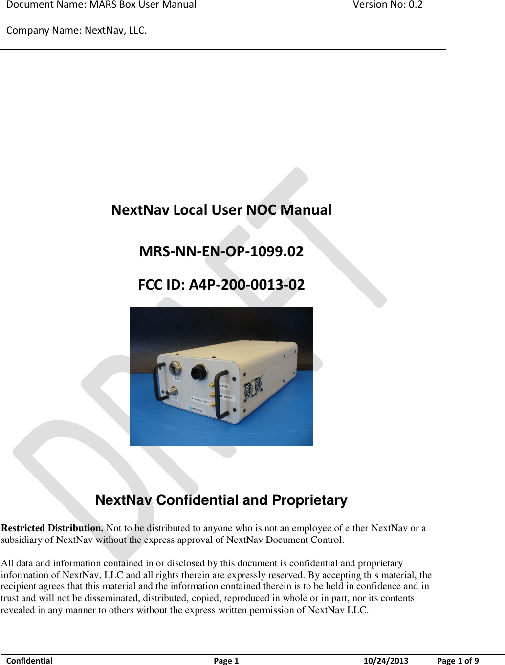
NextNav 200-0013-02 The NextNav Local Beacon will be built, installed and operated by NextNav to provide coverage of the NextNav location service in localized areas such as venues and hot spots User Manual

NextNav,LLC The NextNav Local Beacon will be built, installed and operated by NextNav to provide coverage of the NextNav location service in localized areas such as venues and hot spots Users Manual

Users Manual

Document Name: MARS Box User Manual Version No: 0.2 Company Name: NextNav, LLC.  Confidential  Page 1  10/24/2013 Page 1 of 9    NextNav Local User NOC Manual MRS-NN-EN-OP-1099.02 FCC ID: A4P-200-0013-02   NextNav Confidential and Proprietary  Restricted Distribution. Not to be distributed to anyone who is not an employee of either NextNav or a subsidiary of NextNav without the express approval of NextNav Document Control.   All data and information contained in or disclosed by this document is confidential and proprietary information of NextNav, LLC and all rights therein are expressly reserved. By accepting this material, the recipient agrees that this material and the information contained therein is to be held in confidence and in trust and will not be disseminated, distributed, copied, reproduced in whole or in part, nor its contents revealed in any manner to others without the express written permission of NextNav LLC.
Document Name: MARS Box User Manual Version No: 0.2 Company Name: NextNav, LLC.  Confidential  Page 2  10/24/2013 Page 2 of 9    History  Version Date Author Notes 0.1 May 16, 2013 D. Gautam, W. Kunysz 1 0.2 May 24, 2013 W. Kunysz 2 0.3 Oct 22, 2013 W. Kunysz 3             Notes: 1. Initial Version 2. FCC warning statement 3. Updated FCC ID
Document Name: MARS Box User Manual Version No: 0.2 Company Name: NextNav, LLC.  Confidential  Page 3  10/24/2013 Page 3 of 9    Table of Contents History ........................................................................................................................................... 2 Notes:............................................................................................................................................. 2 1 Introduction ............................................................................................................................. 4 1.1 Purpose and Scope ...................................................................................................................................... 4 1.2 Intended Use ................................................................................................................................................. 4 1.3 FCC Compliance Statements ..................................................................................................................... 4 2 NextNav Local Beacon Commissioning ................................................................................ 5 2.1 Equipment List .............................................................................................................................................. 5 2.2 Confirm External Cable Connections ............................................................................................................... 6 3 Antenna Mounting ................................................................................................................. 8 3.1 TX Antenna .................................................................................................................................................... 8 3.2 Tune-up procedure not to exceed maximum TX power .......................................................................... 9 3.3 GPS Receive Antenna ................................................................................................................................. 9   Table of Figures Figure 1 – MARS Box Front Panel ............................................................................................. 6 Figure 2 – MARS Box Rear Panel ............................................................................................. 7
Document Name: MARS Box User Manual Version No: 0.2 Company Name: NextNav, LLC.  Confidential  Page 4  10/24/2013 Page 4 of 9   1 Introduction 1.1 Purpose and Scope This  document  describes  the  commissioning  and  normal  usage  procedure  for  the NextNav Local beacon box (A4P-200-0013-02).  1.2 Intended Use The NextNav Local beacon system is intended to be used in restricted access locations (RAL) in indoor environments. The NextNav Local beacon is a powered by a DC power system approved for use in telecommunications equipment. 1.3 FCC Compliance Statements FCC Section 15.21 Information to user. Any changes or modifications to the equipment operation settings must be approved by the NextNav, LLC for FCC compliance; otherwise the user's authority to operate the equipment will be voided.  Section 15.105(b) Class A digital device Information to the user This equipment has been tested and found to comply with the limits for a Class A  digital device, pursuant to Part 15 of the FCC Rules. These limits are designed to provide reasonable protection  against  harmful  interference  when  the  equipment  is  operated  in  a  commercial environment. This equipment generates, uses, and can radiate radio frequency energy and, if not  installed  and  used  in  accordance  with  the  instruction  manual,  may  cause  harmful interference to  radio  communications. Operation  of this  equipment  in a  residential area  is likely to  cause harmful interference in  which case the user will be  required  to  correct the interference at his own expense.  RF Exposure Statement This  equipment  complies  with  FCC  radiation  exposure  limits  set  forth  for  an  uncontrolled environment.  This  equipment  should  be  installed  and  operated  with  a  minimum  distance  of 20cm between the antenna and any body part of the user or nearby persons.
Document Name: MARS Box User Manual Version No: 0.2 Company Name: NextNav, LLC.  Confidential  Page 5  10/24/2013 Page 5 of 9   2 NextNav Local Beacon Commissioning Once the NextNav Local Box is installed in the field and the installation checklist is verified, a field technician follows the following sequence of operations to power up the box as illustrated in Error! Reference source not found. and the following checklist can be used for verification of completion of the steps needed.   Installation Tech checklist  1 GPS antenna connection Yes   No   2 Tx antenna connection Yes   No   3 EvDO antenna connection Yes   No   4 SBC: Ethernet port activity Yes   No   5 Rb: Rear Panel LED indicator is lit Yes   No   6 MAIA4: Rear Panel LED indicator is lit Yes   No   7 Able to browse internet from field service laptop using Ethernet port on WAPS beacon box Yes   No   8 Enable port forwarding if not already done at manufacturing site Yes   No   9 TX antenna LLA survey done Yes   No   10 Weather board LLA survey done Yes   No   11 GPS antenna LLA survey done Yes   No   12 Survey ground truth of the TX antenna, GPS antenna and weatherboard Yes   No   Table 1 Commissioning Procedure Steps for Installation Technician 2.1 Equipment List  • NextNav Local Beacon  •  FCC Approved AC/DC Adapter  •   Transmit Antenna (PN: MPA-806-N) •   GPS Antenna (PN: BL1R-A-XTB-1-FKM)  •   EVDO Antenna (PN: PSKN-900/1900S)  •  NextNav WeatherBoard unit    RF cables as per chart below:
Document Name: MARS Box User Manual Version No: 0.2 Company Name: NextNav, LLC.  Confidential  Page 6  10/24/2013 Page 6 of 9    Description Cable Type Cable Length (max) GPS Cable LMR400 150’ AL4RPV-50 250’ Tx Cable LMR400 250’ AL4RPV-50 400’          2.2 Confirm External Cable Connections  Figure 1 – MARS Box Front Panel 1. Verify the following external connections to the beacon: a) GPS antenna connection to the MARS Box b) Tx antenna cable connection to the ‘TX’ port. c)           Weather box connection to the RJ45 WEATHER port. d) EvDO antenna cables to the EvDO Tx port. In cases of sites which have been documented as requiring EvDO diversity, connect the diversity antenna to the EvDO DIV port. In cases of sites which have been
Document Name: MARS Box User Manual Version No: 0.2 Company Name: NextNav, LLC.  Confidential  Page 7  10/24/2013 Page 7 of 9   documented as needing a POTS line, connect the phone line to the ‘TELCO’ port. 2. Verify that the following LEDs (located at the rear panel) are lit indicating proper operation: a) Rubidium: Power Switch LED and status indicator LED are lit b) MAIA4: Status indicator LED is lit   Figure 2 – MARS Box Rear Panel 3. Connect the field service laptop with an Ethernet cable to the ‘Ethernet’ port on the MARS beacon box. Wait for a few seconds to get an IP address on the field service laptop. Try and browse the internet to ensure connectivity. Once connectivity is ensured, call the operator at the NOC to further commission the beacon box.
Document Name: MARS Box User Manual Version No: 0.2 Company Name: NextNav, LLC.  Confidential  Page 8  10/24/2013 Page 8 of 9   3 Antenna Mounting 3.1 TX Antenna Tx antenna will be installed indoors. In normal configurations, antenna is to be attached to the ceiling  structures.  Proper  installation  procedures  must  be  followed  as  defined  in  site  specific construction drawing. As a general rule the TX antenna shall be kept a minimum distance of 6 feet from any metallic vertical structures on other types of obstructions.   This radio transmitter (FCC ID: A4P-200-0013-01) has been approved by FCC to operate with the antenna  types  listed  below  with  the  maximum  permissible  gain  and  required  antenna impedance for each antenna type indicated. Antenna types not included in this list, having a gain greater than the maximum gain indicated for that type, are strictly prohibited for use with this device.   This radio transmitter may only operate using a vertically polarized antenna with maximum net gain of antenna and cable of +6 dBi. To reduce potential radio interference to other users, the antenna gain should be so chosen that the effective radiated power (ERIP) does not exceed 4 Watts.  Antenna Type: Monopole  Polarization: Vertical  Following is a list of the possible antennas and antenna cables combinations. Antenna type Antenna Gain (dBi) Cable Type Length (feet) Cable Loss (dB) Attenuation Setting (dB) PA output (Watts) EIRP (W) (PEP) MPA-806-N (omni config) 2.5 LMR400 10’ 0.4 1.0 0.85 1.38 AL4RPV-50 10’ 0.2 1.0 0.85 1.45 MPA-806-N (90° sector config) 7.0 LMR400 10’ 0.4 1.0 0.85 3.89 AL4RPV-50 10’  0.2 1.5 0.35 3.63 Table 2 – NextNav Local antenna and cable options Note: PA output level (controlled using internal attenuation setting) refers to internal system parameter. This parameter will be used by the NOC to configure the radio output power.
Document Name: MARS Box User Manual Version No: 0.2 Company Name: NextNav, LLC.  Confidential  Page 9  10/24/2013 Page 9 of 9   3.2 Tune-up procedure not to exceed maximum TX power A CSV file (configuration file) per transmitter are created by the NOC engineer based on the installation parameters such as line lengths, antenna type etc. The TX output power level setting is contained in the CSV file.   The output power is adjusted by the ‘attenuation’ setting.  This value in the CSV file is calculated by a formula to set the output power (not to exceed 4W EIRP). The variables used in the calculation include PA Gain (Gpa), TX Antenna Gain (Gant), TX filter insertion loss (ILflt), internal cable loss (ILint), external cable loss (ILext), and transceiver output power (PTCVR).   EIRP (W) = 10^((PTCVR - ILint + Gpa - ILflt - ILext + Gant) / 10) / 1000 3.3 GPS Receive Antenna GPS antenna should be installed such that it has clear view of sky. Ideally, you would keep the antenna close to the ground away from obstruction   • Keep any horizontal blockage smaller than 10 degrees  • Obstruction Clearance guideline  – If it is 1 ft wide it should be at least 6 ft away  – If it is 10 ft wide, it should be at least 60 ft. away.  – If it is significantly less than 1 ft wide (like a guy wire, or a post) it should not cause any measurable effect

Navigation menu