Nextivity orporated P24512NU Provider Specific Consumer Signal Booster User Manual 1
Nextivity Incorporated Provider Specific Consumer Signal Booster Users Manual 1
Contents
- 1. Users Manual 1
- 2. Users Manual 2
- 3. Users Manual 3
Users Manual 1
NOTE: The brackets come equipped with screws and inserts for mounting in stan-
dard drywall. Before you install the mounts, make sure there are no wires or other
objects, or metal plates, behind the drywall layer that will interfere with the in-
serts, screws, or mount, or mounted units.
NOTE: The Network Unit only has mounting holes on the back. The Coverage Unit
has mounting holes on the bottom and on the back. The holes on the bottom of the
Coverage Unit can be used for mounting the Coverage Unit on a ceiling. (See 6b)
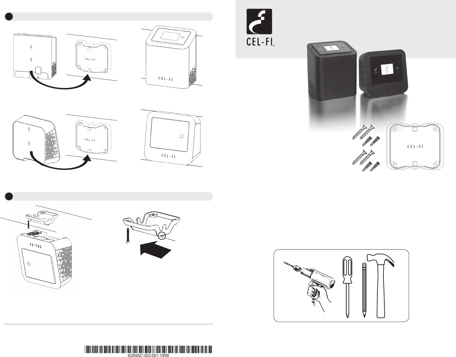
REQUIRED HARDWARE
Copyright © 2014 by Nextivity, Inc, U.S. Patents pending. All rights reserved. The Nextivity and Cel-Fi logos are registered trademarks
of Nextivity Inc. All other trademarks or registered trademarks listed belong to their respective owners. Designed by Nextivity Inc in
California.
Each Cel-Fi Device may be supplied with
mounting brackets and hardware to
mount both (or either) the Coverage
Unit and the Network Unit.
form-bracket-PRO-English_14-0515
Mounting Instructions
for Cel-Fi PRO
For more information, refer to the Quick Start Guide or visit www.cel-.com CEL-FI PRO SMART SIGNAL BOOSTER
6Attach the Cel-Fi Unit to the wall mounted bracket.
6b Optional: Attach the Cel-Fi Unit to a ceiling mounted bracket.
Network Unit
Coverage Unit
For more information, visit www.Cel-Fi.com
Network
Unit
Coverage
Unit
To ensure ceiling mounting is as secure
as possible, confirm that the mounting
bracket posts are firmly inserted, and in
the correct position.
(x4)
Coverage Unit
Upside Down
(x4)
Slide Coverage
Unit until secure.
Mounting
Posts
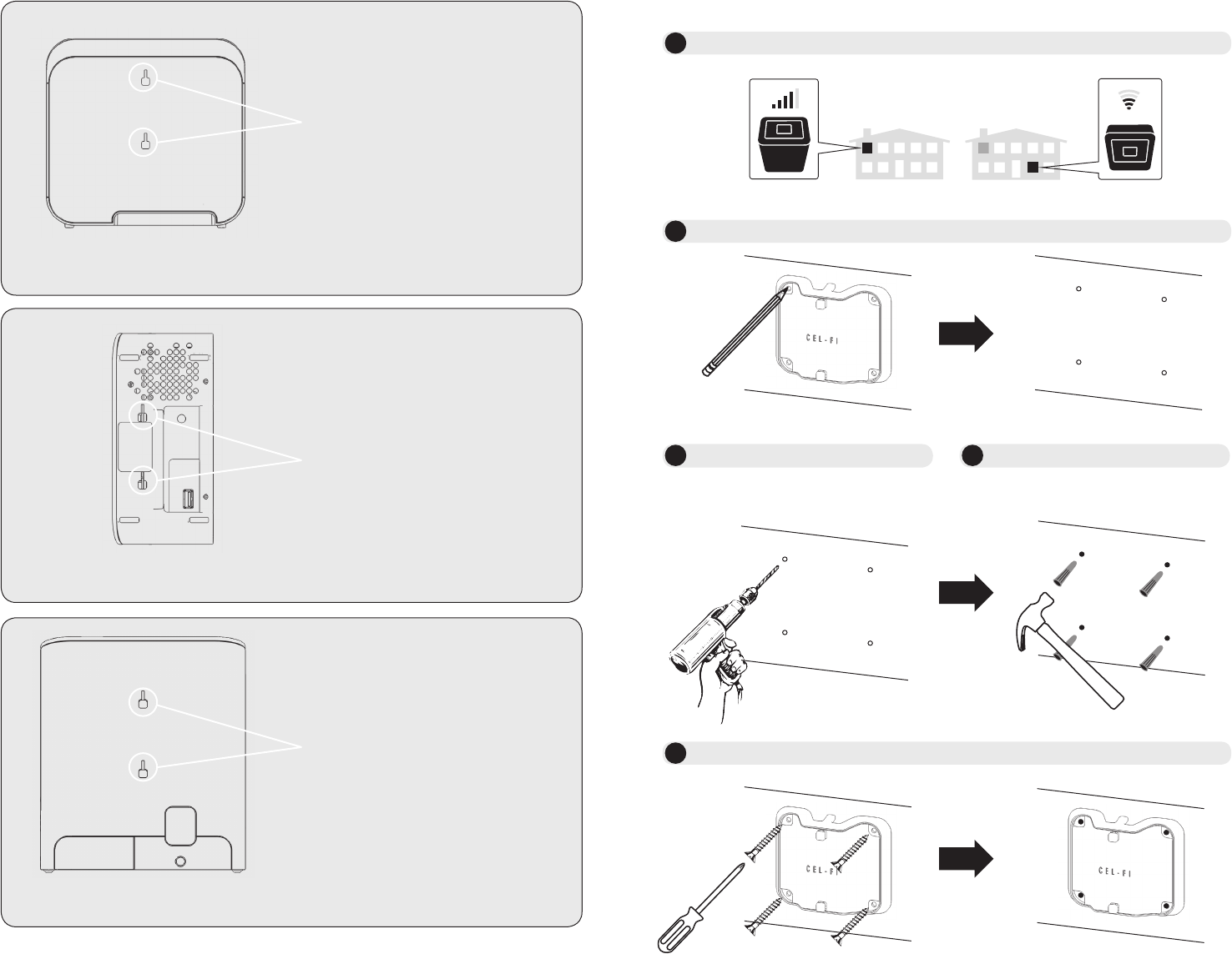
Figure 1. Coverage Unit, back view with mounting holes.
Figure 2. Coverage Unit, bottom view of mounting holes.
Figure 3. Network Unit, back view of mounting holes.
For more information, refer to the Quick Start Guide or visit www.cel-.com CEL-FI PRO SMART SIGNAL BOOSTER
Coverage Unit
Back Mounting Holes
Coverage Unit
Bottom Mounting Holes
Network (Window) Unit
Back Mounting Holes
1Determine Cel-Fi Device Location (refer to Quick Start Guide)
2Determine Mounting Hole Locations
3Drill Anchor Holes (Drywall) 4Install Anchors (Drywall)
3G/4G/LTE
NetworkUnit
CoverageUnit
In each marked spot, use a 3/16” drill
bit to drill guide holes for the anchors.
5Install Mounting Bracket