Nextivity orporated Q34-251266NU Provider-Specific Consumer Signal Booster User Manual manual QUATRA 16 0614 v5
Nextivity Incorporated Provider-Specific Consumer Signal Booster manual QUATRA 16 0614 v5
Contents
- 1. User Manual
- 2. User Manual II
User Manual II
USER MANUAL
NETWORKED SMART BOOSTER 1
INTRODUCTION: Cel-Fi QUATRA ................................................................................................................................................2
CONFIGURATIONS: Cel-Fi QUATRA System ...........................................................................................................................2
OVERVIEW ....................................................................................................................................................................................... 3
PLANNING .......................................................................................................................................................................................3
Decide on the System Configuration ..............................................................................................................................3
Plan NU Placement based upon System Configuration .............................................................................................4
Plan CU Placements ............................................................................................................................................................5
Plan Cabling...........................................................................................................................................................................6
System Installation ..................................................................................................................................................................7
STEP 1 — Record QUATRA serial numbers. ..................................................................................................................7
STEP 2 — !"#$%&'()*+)&,-./0-.1..........................................................................................7
STEP 3 — !"#$%&'()&*"((%*$&'++&,'$&-%&."/&0%$$%/1............................................................................................8
STEP 4 — !"#$%&'($&)$'#"%*&+,-'&.,/&0"11-22-",&'($&232'$1.........................................................................9
TROUBLESHOOTING:
Quatra ....................................................................................................................................................................................... 11
Accessories.............................................................................................................................................................................. 12
SPECIFICATIONS ........................................................................................................................................................................ 12
TERMINOLOGY ........................................................................................................................................................................... 13
FCC STATEMENT........................................................................................................................................................................ 13
WARRANTY ................................................................................................................................................................................. 13
Cel-Fi QUATRA
Networked Smart Booster™
Cellular Coverage for your Business
COVERAGE
UNIT
COVERAGE
UNIT
COVERAGE
UNIT
COVERAGE
UNIT
NETWORK
UNIT
TABLE OF CONTENTS
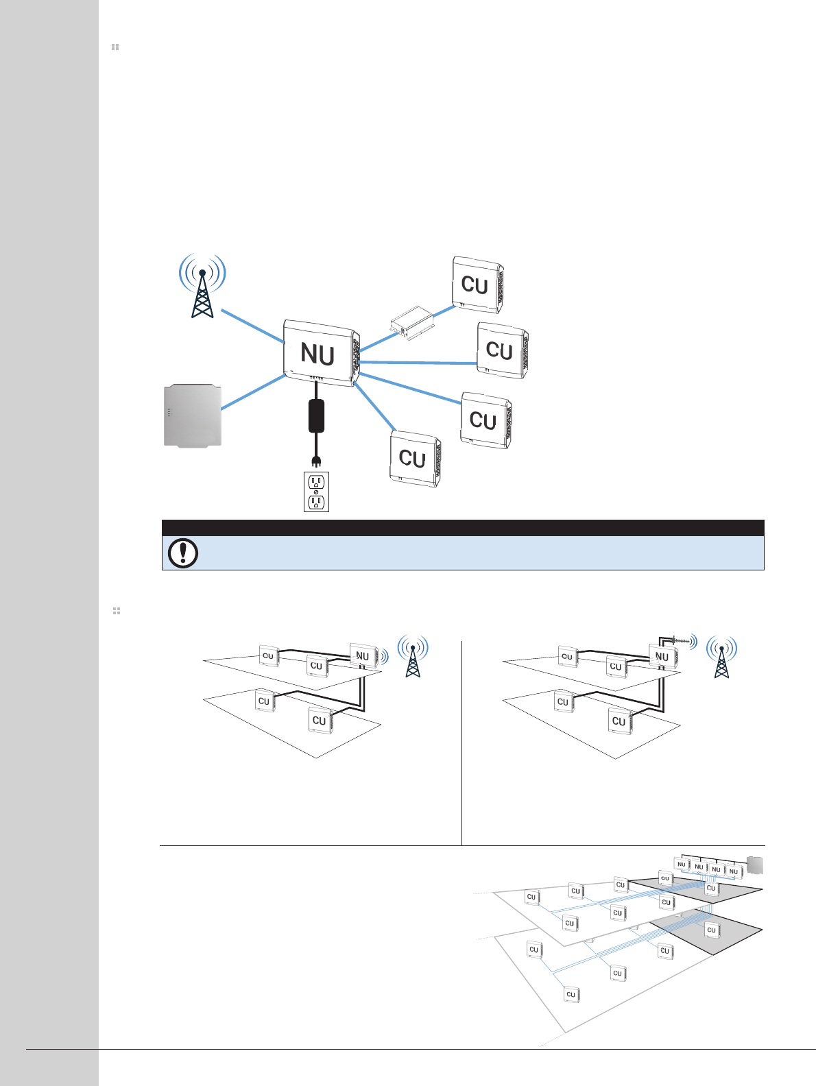
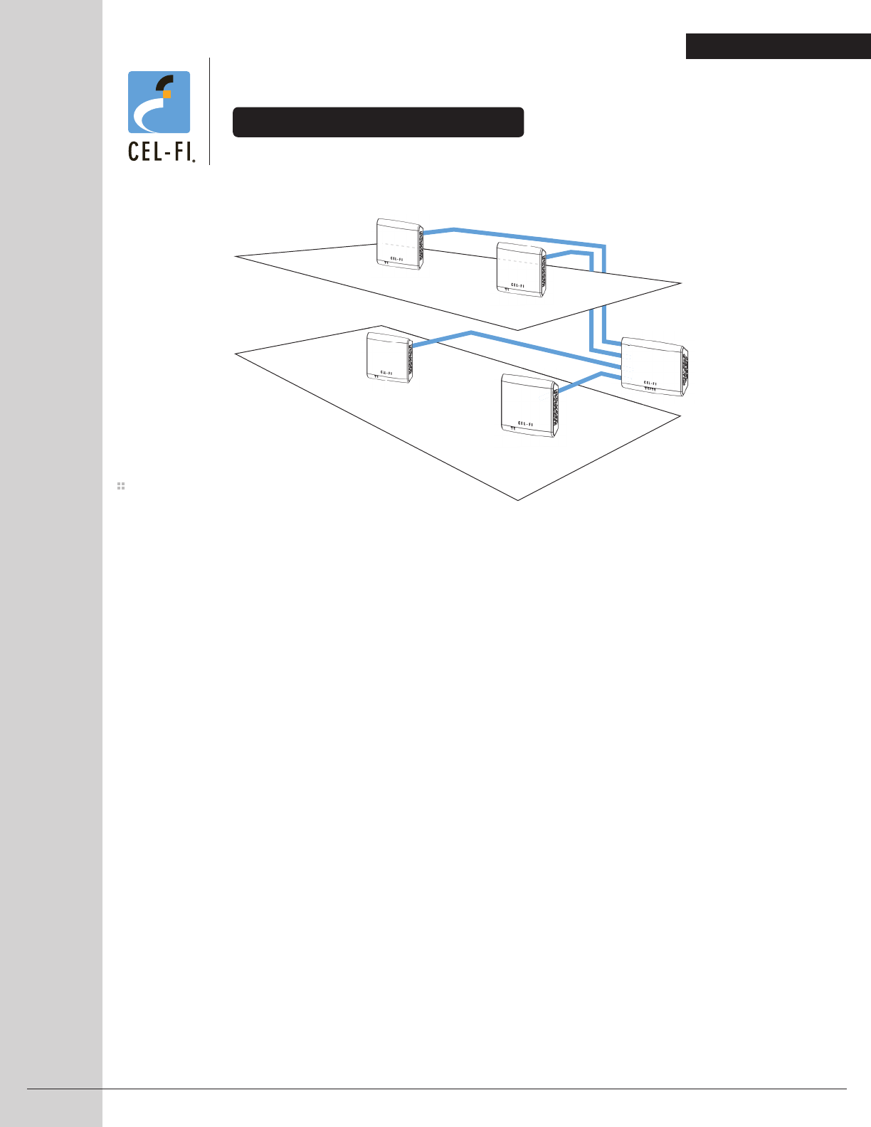
Cel-Fi QUATRA is a simple to install 3G/4G/LTE enterprise class Networked Smart Booster™. A single system is
comprised of one Network Unit (NU) and up to four Coverage Units (CU). The NU accepts Donor signals from
either the outside cellular network or a locally installed Small Cell, and passes that service over Cat 5e (or better)
cabling to CUs mounted where cellular service is needed.
The CUs contain their own transmit amplifiers and are powered from the NU through Power over Ethernet (PoE).
This allows for flexible placement of the CU’s since AC power at the site of each CU is not required.
With four (4) Coverage Units, a combined in-building coverage range of up to 50,000 ft2 per system can be
achieved. For larger coverage area, multiple QUATRA systems may be used.
Cel-Fi QUATRA systems are self-configuring and can be fully managed from Nextivity's WAVE Portal. Status
notifications and alarms are fully customizable.
P
S
U
SMALL CELL
Cat 5e or better
200 meter max
with Extender 100m
100m
100m
100m
Donor
Options
NU = NETWORK UNIT
CU = COVERAGE UNIT
INTRODUCTION: Cel-Fi Quatra
CONFIGURATIONS (MODE): Cel-Fi QUATRA System
BEST FOR: Basic install if an excellent
donor signal exists somewhere inside the
building, and coverage in a remote area is
the main problem.
Off-Air Donor
using Internal
Antennas
BEST FOR: Most off-air installations. This is
the recommended use case of an off-air
QUATRA system.
Off-Air Donor
using External
Antennas
BEST FOR: Large scale deployments to add
dedicated local capacity or to resolve interfer-
ence issues. Use this configuration when
connecting a small cell to one or more
QUATRA systems.
Small Cell
Donor
NETWORKED SMART BOOSTER 2
COVERAGE UNITS (CU)
• Up to four (4) per NU
• Power over Ethernet
• Built-in or External antennas
• Horizontal ceiling or vertical wall mountable
• Mounting Kit included
NETWORK UNIT (NU)
• Built-in or external donor antennas
• Accepts Small Cell donor inputs
(to one or more QUATRA systems)
• Powers entire system
• Self-configuring
• Mounting Kit included
• Enterprise management
COVERAGE
UNIT
COVERAGE
UNIT
COVERAGE
UNIT
COVERAGE
UNIT
COVERAGE
UNIT
COVERAGE
UNIT
COVERAGE
UNIT
COVERAGE
UNIT
SMALL
CELL
We recommend watching the QUATRA videos on www.Cel-Fi.com as a quick way to learn about the
system and how to install it.
IMPORTANT
Decide on your configuration and where QUATRA components will go, including NU to CU interconnect cables to
make sure their lengths do not exceed 100 meters per CU (200m with QRE — QUATRA Range Extender).
Use the table below to determine the recommended donor input configuration for your installation site. Off-Air
donor refers to the use of antennas to receive and redistribute the outdoor macro network service where you need
it indoors. Small Cell donor refers to the use of a dedicated small cell device (usually available through your opera-
tor) as the network signal source.
When amplifying the existing outdoor network, service is being shared with other users on the macro network
(your outside cellular experience should become your inside cellular experience). When using a dedicated small
cell input, capacity is being added to the operator’s network at your install site which also helps resolve capacity or
interference problems.
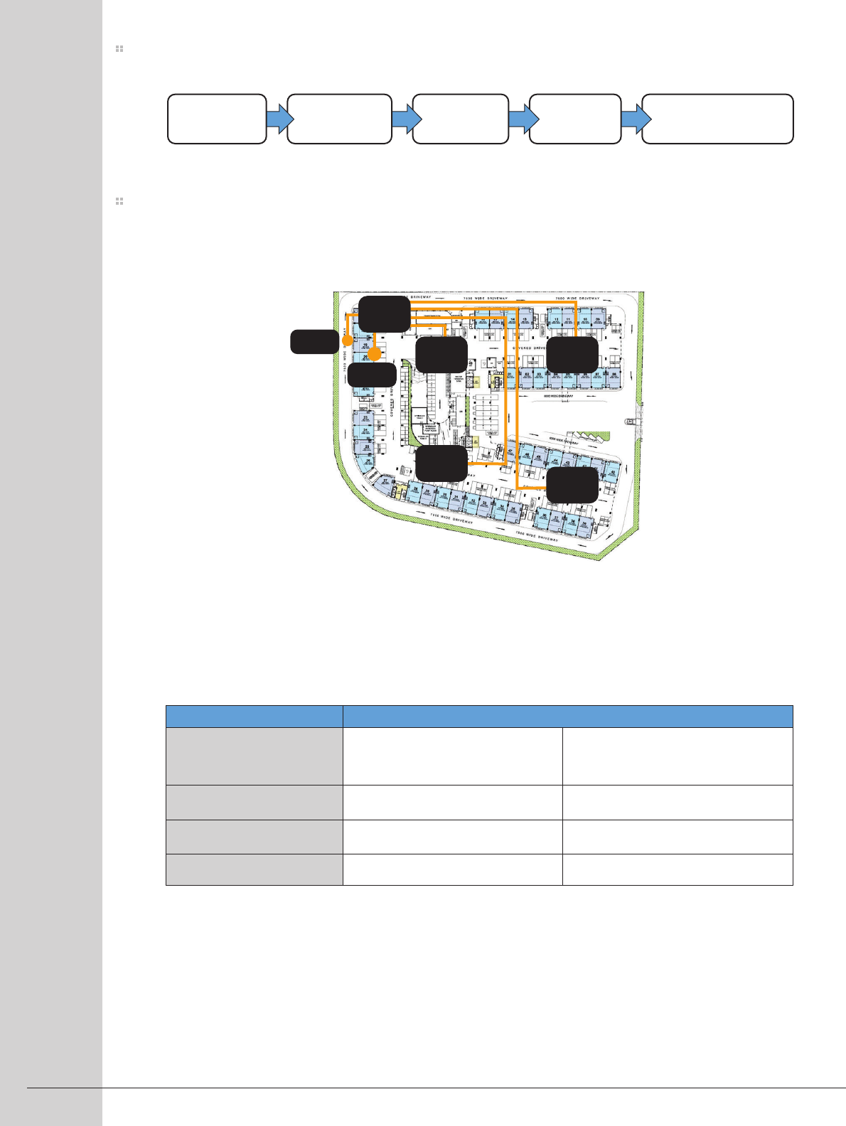
COMMISSIONPOWERCABLEINSTALLPLAN
NETWORKED SMART BOOSTER 3
Decide on the System Configuration (Mode)
LAN
PWR
NU
CU1CU2
CU3
CU4
Cables up to 100m
(200m with QRE)
!"#$%$$$"&'2 open area
("#$%$$$"')"*$$%$$$"&'2
Off-Air input Small Cell input (may need >1 QUATRA)
*$%$$$"&'2 many walled rooms Off-Air input
Coverage Need Weak Cellular service (0-2 bars),
reliable calls where signal exists.
Signal exists but calls unreliable, or
available small cell does not cover all
required areas.
Small Cell input
Small Cell input to multiple QUATRAsSmall Cell input to multiple QUATRAs
Existing Service using your phone (bars of signal)
Table 1 — Recommended Donor Source
OVERVIEW
PLANNING
NETWORKED SMART BOOSTER 4
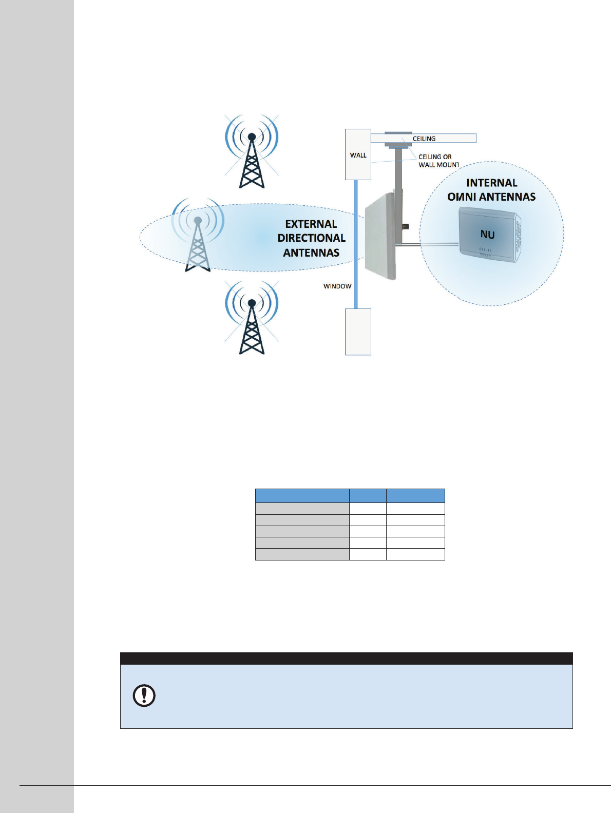
Off-Air Donor
To meet regulatory compliance and to assure optimum performance, the approved Cel-Fi External Antenna
must be used (refer to Legal Insert for a list of approved antennas). The WAVE Portal is used to simplify this
step. For applications in rural areas, the internal antennas of the NU may be used.
For best results, test donor signal locations during normal peak usage hours.
1. Determine best existing Off-Air signal location in the building (using phone signal bars), usually near
windows.
a. OPTION: Run a few speed tests on a phone at each location. Higher data rates indicate better signal
quality.
b. ADVANCED: Evaluate signal quality parameters (LTE: RSRQ and SINR/CINR; WCDMA: Ec/Io or CQI).
2. NU Internal antennas are sufficient if signal quality is good. If signal quality is poor, use an external antenna.
3. NOTE: The approved external antenna supplied by Nextivity is intended for indoor use. If the antenna is to be
mounted outdoors, the installer is responsible for proper lightning surge protection and cable weatherproof-
ing (sold separately).
NU Placement based upon System Configuration
<-15
<0
0
<-16
0
LTE RSRQ dB
LTE SINR dB
LTE CQI
WCDMA Ec/Io dB
WCDMA CQI
-3
+30
15
-3
30
QUALITY INDICATORS POOR BEST(MAX)
TIPS FOR NU PL ACEMENT
• Plan to mount the NU within reach of an AC outlet.
• Plan cabling from the NUs to the CUs (use existing unused LAN distribution cables from a
central patch panel, or plan to run new cables).
• If using internal NU antennas, it is best to not run or coil the cabling immediately behind the NU
to avoid effects of metal close to the antennas.
Small Cell Donor:
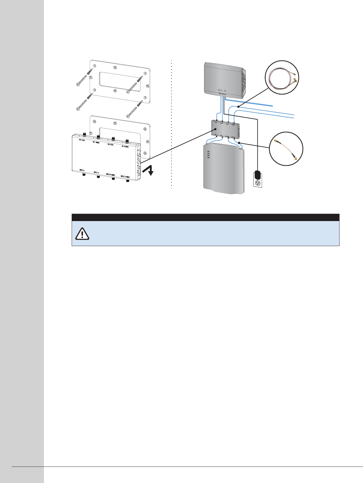
This configuration connects one or more NUs directly to a small cell through a Small Cell Interface (SCIF) for
signal distribution. Plan to mount both the small cell, SCIF and NU next to each other, and where there is easy
access to LAN cabling and routing (such as an IT closet with pre-existing LAN patch panels).
NETWORKED SMART BOOSTER 5
Cabling Between the Small Cell and QUATRA
The QUATRA Small Cell Interface (SCIF) shown above contains the proper amount of signal attenuation and
port isolation needed when connecting up to four (4) small cell RF ports to the RF ports of one or two QUATRA
NUs. Choose the small cell to match the overall capacity you need and match the QUATRA system size to
achieve the coverage you need. If more than two (2) QUATRA systems are to be used, contact your supplier or
www.cel-fi.com/quatra for more information.
Installation Considerations for NUs and SCIF:
• Plan to mount all NUs and the small cell in the same location so they may be properly interconnected using
the SCIF.
• The SCIF should be mounted above the Small Cell within reach of the Input RF cables.
• Make sure there is a suitable power outlet within reach of the NU power supply.
• Make sure there is room to route CU, LAN, power, and optional RF cables.
• Allow adequate ventilation.
• Do not place the NU close to other transmitting antennas.
• NU Faceplate LEDs should be clearly visible.
IMPORTANT
To prevent damage or out of specification operation, a QUATRA Small Cell Interface (SCIF) must be
used when connecting QUATRA systems to a small cell.
The actual cabling between the small cell and QUATRA is described in the installation section of this guide.
SCIF
SCIF
SMALL CELL
NU
OPTIONAL
2nd QUATRA and cables
PSU
NU to CU Ethernet cables
QMA TO SMA
Output RF cables
(to QUATRA)
SMA TO SMA
Input RF cables
(from Small Cell)
CU Placements
NETWORKED SMART BOOSTER 6
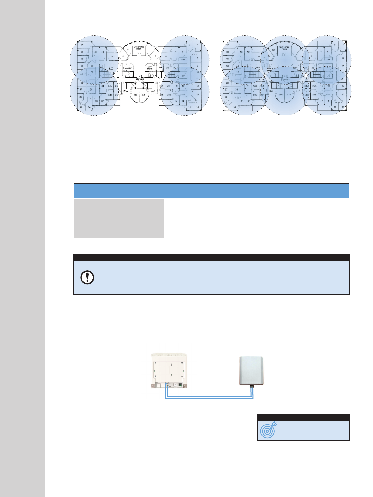
Off-Air Donor Coverage Units Where Needed
For Off-Air installs, mount Coverage Units where the
macro network does not reach. Example, if a
100,000 ft2 warehouse only lacks service in a few
locations, then only use CUs in those locations.
Small Cell Donor Contiguous Coverage Units
For Small Cell donor configurations, mount the CUs
to create continual coverage to ensure all areas
benefit from the added small cell capacity.
CU CU
CU CU
CU CU
CU
CU
CU CU
33 meters
21 meters
14 meters
11 meters
Open areas
(warehouse, parking structure)
Open office plan (cubicles)
Closed office plan (framed walls)
Closed room plan (masonry walls)
50 meters
32 meters
21 meters
16 meters
Approximate Service Area
(Coverage Unit) Approximate Coverage Radius
(Isolated Coverage Unit) Distance Between Coverage Units
(Contiguous Coverage)
Table 2 – General CU coverage estimates
Coverage Unit External MIMO
Service Antenna
50 ohm
Cables and
Antenna
OPTIONAL: CU External Antennas
CUs contain internal omnidirectional MIMO antennas, and they are also equipped with external antenna ports in
the event that directional antennas are desired, or if the signal needs to be split to feed multiple service antennas
(splitter and cable losses will result in lower transmit power at the service antennas).
If external antennas are desired, place and mount the external antennas
according to the antenna manufacturer’s instructions and connect to the
RF ports on the back of the Coverage Unit. Ask your QUATRA supplier
about antenna cables.
IMPORTANT
• For best performance, mount the CU in an elevated position in open space.
• CU faceplate LEDs should be clearly visible.
• Off-Air Only: For maximum CU transmit power, do not mount CUs close to the NU antenna or the
CU may reduce its transmit power to prevent RF feedback.
TIPS FOR CU PL ACEMENT
OPTIONAL: QUATRA Range Extender (QRE)
NETWORKED SMART BOOSTER 7
Cabling
QUATRA Cabling considerations
NU Power
• The NU should be located within reach
of an AC power output.
NU LAN Management port (located on back
of NU)
• The NU LAN port connects QUATRA to
WAVE Portal through your LAN/ISP.
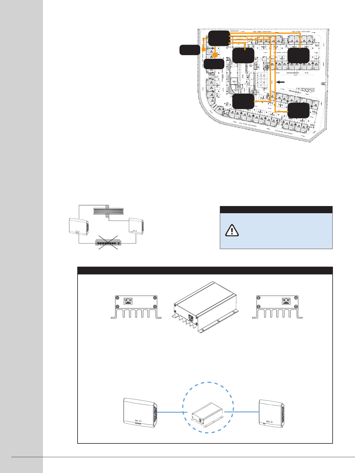
NU to CU cables
• Cat 5e (or better) must be used.
• These cables must not exceed 100
meters in length (unless a QUATRA
Range Extender is used – see below).
• These cables must be dedicated to each CU.
• Passive cable interconnects may be used when routing the cables (such as a punch-down block or patch panel).
• Active Ethernet LAN hardware may not be used because QUATRA uses proprietary signaling.
For NU to CU cable lengths exceeding 100m, a QRE may be used to extend cables up to 200m.
• Only one QRE may be used per CU.
• The QRE is powered by the cable from the NU (no local power source is needed).
• Install the QRE in accordance with the QRE User Manual.
INPUT
OUTPUT
QUATRA
NETWORK UNIT WITH QUATRA
RANGE EXTENDER
QUATRA
COVERAGE UNIT
Cat 5e cable
100 meter max
Cat 5e cable
100 meter max
Longest
cable 100m
NU
LAN
PWR
CU1CU2
CU3
CU4
Passive Interconnect OK
Active Interconnect NOT OK.
(routers/switches etc.)
NU to CU Ethernet cables must be
dedicated (proprietary data link)!
The system will not function if
common shared LAN resources are
used (routers, switches etc).
IMPORTANT
OPTIONAL: QUATRA Range Extender (QRE)
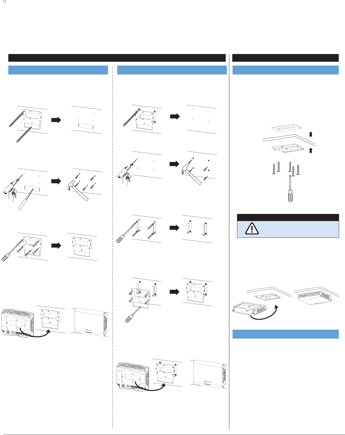
Attach plastic mount on to the FRONT side of
the ceiling tile with screws. The screw ends will
be exposed on BACK side of ceiling tile. Attach
metal plate on to the BACK side of the ceiling tile
using the exposed screws.
Plug cables into BACK side of unit and place
BACK side of unit against plastic mount. Align
the four holes over the four hooks and press
downward until unit snaps into place.
!"#$%&&'(("#)$*+(,%--%,*"+.$/-'%('$#'0'#$,"$,1'$
*+(,#2&,*"+($*+&-2-3'3$4*,1$,1'$%&&'(("#)
The QUATRA Management tools will reference the NUs and CUs by serial number during commissioning, and allow the
assignment of personalized names to each unit.
STEP 1: Record QUATRA NU and CU serial numbers by location
STEP 2: Mount QUATRA Hardware
WALL MOUNT CEILING MOUNT
Network Unit or Coverage Unit Network Unit Metal Stand-off Brackets Coverage Unit Ceiling Tile Mount
Accessories
NETWORKED SMART BOOSTER 8
Drill holes into wall. Use a hammer to insert dry
wall anchors. OPTIONAL: Cut rectangular area
for cables with a dry wall saw.
Attach the plastic mount to the wall with drywall
screws. OPTIONAL: Route cables thought wall
cutout.
Plug cables into BACK side of unit and place
BACK side of unit against plastic mount. Align
the four holes over the four hooks and press
downward until unit snaps into place.
Mark screw holes on plastic mount (A) onto wall.
OPTIONAL: Trace rectangular area (B) if you are
planning to run the cables through the wall.
Temporarily attach metal brackets to plastic mount
with machine screws. Mark screw holes on metal
brackets onto wall.
Drill holes into wall. Use a hammer to insert dry
wall anchors.
Attach the metal brackets to the wall with
drywall screws.
Attach the plastic mount to the metal brackets
with machine screws.
Plug cables into BACK side of unit and place
BACK side of unit against plastic mount. Align
the four holes over the four hooks and press
downward until unit snaps into place.
A
B
Do not overtighten the plastic
mount screws.
IMPORTANT
Front Side
Back Side
Plastic plate
Metal plate
SYSTEM INSTALLATION
STEP 3: Route and connect all Cat 5e (or better) cables
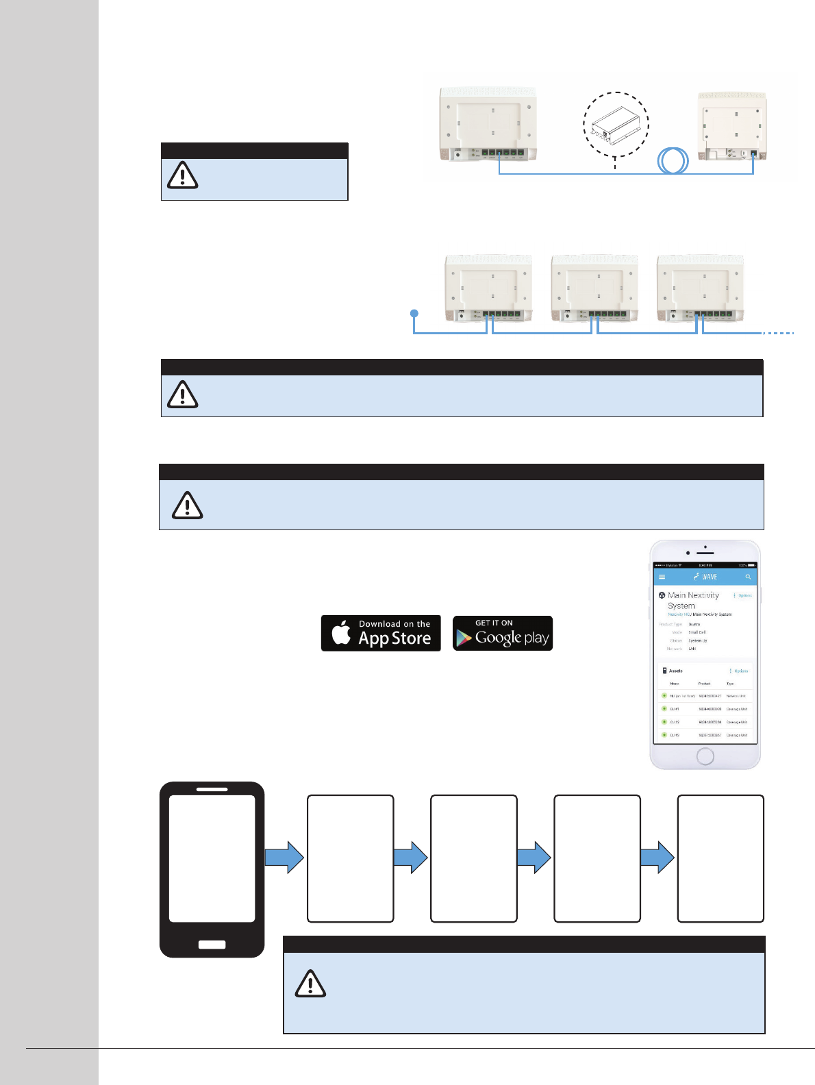
STEP 4: Power the Network Unit and Commission the system
LAN Cables are not provided with unit. End-use installer must choose correct LAN / PoE cables. The LAN cable
must be as per requirements of CEC / NEC.
NU Management Connections
A. Once a donor signal is available to the NU (Off-Air or Small Cell), plug in the NU
power supply.
B. Download and launch the QUATRA Management Tool (QMT) app from Google Play
or the Apple App Store.
C. Follow the on-screen prompts to connect to the QUATRA system over Bluetooth
and complete the guided Commissioning steps (you must be within Bluetooth
range of an NU or CU).
D. Once Commissioning is completed, your QUATRA system should be providing service
(the NU and CU front panel LEDs should be solid Green). If an LED is blinking green,
wait for setup to complete. If any red LED indications persist, see Troubleshooting.
NU
LAN
ISP NU NU
NETWORKED SMART BOOSTER 9
Commission
Settings
• Dashboard
• Alarms
• Help
Register and
Software
update
(if needed)
QMT Connects
your QUATRA
to the cloud
Connect to
QUATRA over
Bluetooth
NU CU
Optional QRE
Connect CUs in order CU1, CU2... (recommended)
If unsure of CU placement, leave extra cable to
allow for CU relocating.
If multiple NUs are used for a Site, it is
recommend to daisy chain the NU manage-
ment ports (OUTPUT-LAN-OUTPUT-LAN…),
or connect all NU LAN ports to the same
LAN Subnet.
Do not power up the
Network Unit at this time.
IMPORTANT
Remember to set Mode when commissioning the Unit. Choices are: Internal Antenna, External
Antenna, or Small Cell.
IMPORTANT
1) If using a Small Cell, complete Small Cell commissioning before powering up.
2) QUATRA commissioning using QMT or the WAVE portal is required for operation.
IMPORTANT
IMPORTANT
• Make sure that Mode is properly set to Internal Antenna, External Antenna, or
Small Cell using QMT or WAVE Portal.
• Make sure donor signal source is operational before powering up QUATRA.
• If any alarms, see Troubleshooting below.
NU to CU Cabling
For detailed diagnostics,
use the QMT app or the
WAVE Portal
IMPORTANT
NETWORKED SMART BOOSTER 10
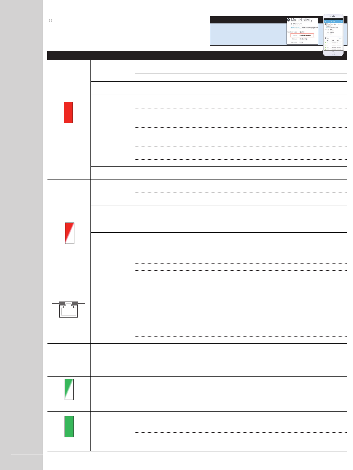
Troubleshooting: QUATRA
Network Unit error. Reset the Network Unit by unplugging the power supply, wait 5 seconds, then plug it back in.
Verify Network Unit software is up to date (using QMT or cloud portal).
If the problem persists, return Network Unit for service.
Make sure that the vents (the small openings in the plastic housing) on the units are not blocked. Move the unit to
a cooler area. The system will start working normally when it cools down.
Reset the Coverage Unit by unplugging it and then plugging it back in.
Verify Coverage Unit software is up to date (using QMT or cloud portal).
Make sure that the LAN cabling to each Coverage Unit is dedicated (not combined with other active LAN hardware
such as routers and switches). Passive connectors may be used (i.e. punch-down blocks) but the maximum cable
distance may be reduced.
If a QUATRA Range Extender is used to lengthen the 100 meter maximum Network Unit to Coverage Unit Ethernet
distance, make sure only a single QUATRA Range Extender (QRE) is used per Coverage Unit. QRE is proprietary and
other extenders will not work. See QRE Troubleshooting.
Uninstall Coverage Unit and plug it into back of Network Unit with a short Ethernet cable that is known to work. If
the Coverage Unit works properly, troubleshoot the original Ethernet cable (or QRE if used).
If the problem persists, return Coverage Unit for service.
Make sure that the vents (the small openings in the plastic housing) on the units are not blocked. Move the unit to
a cooler area. The system will start working normally when it cools down.
Insufficient Donor Signal. If internal antennas used for Network Unit, relocate Network Unit where signals exist or
add and Enable external antennas in Settings.
If external antennas or Small Cell donor signal used, verify external antennas Enabled in Settings and check coaxial
feeds and connectors to Network Unit.
Product Registration is required for your system to operate. Please follow the registration instructions using QMT
or the WAVE portal.
The system has been remotely disabled. Please check for a notification message and contact your Operator or
Vendor.
The Network Unit is receiving too strong a donor signal and may operate with reduced gain or may switch to internal
antennas to protect itself (the signal source could be any Operator’s cell tower if close enough, or it could be
another indoor cellular solution in close proximity to the Network Unit donor antennas).
If internal antennas used, move the Network Unit to another location. You might need to move your system to the
other side of your building.
If external antennas used, move or re-aim the external antennas away from the strong cellular signal source.
If a Small Cell donor is used, make sure the coaxial connections to the Small Cell have the supplied attenuators
installed.
Your system has been moved from its previous Registration location. Please reregister your system at its new
location using QMT or the WAVE portal, or move the system back to its original location.
A Coverage Unit LAN cable may be shorted. Unplug all Coverage Units, power cycle the system, and plug Coverage
Unit cables back in one at a time to check where fault occurs (fault could be in cabling, a QUATRA Range Extender,
or a Coverage Unit).
If QUATRA Range Extenders are used, verify that LAN cable length on either side of the Extenders does not exceed
100 meters.
If none of the above works, try another power supply.
If none of the above works, try another Network Unit.
Verify that a live LAN Ethernet cable is connected to the Network Unit LAN port (not the LAN OUT port which is used
to daisy-chain to another Network Unit LAN port).
Check LAN firewall settings to the cloud (contact your IT Administrator).
Verify system performance and WAVE cloud portal connectivity using QMT (QMT must have an active internet
connection).
Wait. System is in a setup state, which usually takes a few minutes but can take up to thirty (30) minutes if scanning
for new channels in all bands.
If using a Small Cell donor, make sure the small cell is commissioned and transmitting.
Make test calls using just the Small Cell signal to verify its operation.
Verify handset settings and compatibility against boosted channel bands and 3G/4G technologies.
Advanced: Cellular connection problems are usually indicated by poor signal quality (3G:Ec/Io and CQI, LTE: RSRQ
and SINR). Using a Small Cell can help eliminate
Capacity and Interference problems that may be experienced from Off-Air donor signals.
Network Unit
overheating.
Coverage Unit
overheating.
Donor power
below minimum
Threshold.
Registration
required.
System disabled.
Input signal
too strong.
Location Lock —
Registration Required
Port keeps resetting
Management
Connection Error
Setup in progress
Phones have signal
but can't make calls
Coverage Unit
(CU) Error
SOLID RED
BLINKING GREEN
All RJ45 port LEDs
flash off
repeatedly
QMT/WAVE
LED ISSUE TRY
BLINKING
RED
QMT/WAVE
SOLID GREEN
LED ISSUE TRY
12

NETWORKED SMART BOOSTER 11
Specifications
QRE – ALL LEDs
FLASHING
Any RJ45 green
LED is off
between
NU/QRE/CU
Supported Bands 2, 4, 5, 12
WCDMA Bandwidth per Band 3.84, 5, 10, 15, 20 MHz contiguous UMTS/HSPA channels
LTE Bandwidth per Band 5, 10, 15, 20 MHz contiguous (up to band max)
Channel Selection Full Auto with self-learn Scan
Downlink TX Power max (conducted) 10dBm/5MHz (16dBm per band per antenna, 19dBm per band)
Uplink TX power max (conducted) 22dBm per band per antenna, 25dBm total per band
Max boost bandwidth (all channel) 75MHz
Maximum System Gain 100dB
System Gain dynamic range 0-100dB (real time echo controlled)
Internal MIMO antenna gains 0-2dBi (band dependent) V-H polarization
External RF connections 50 ohm QMA female Quick-Connect
Ethernet ports Shielded Fast Ethernet ports (RJ45)
Maximum NU-CU cable length 100 meter (200 meter with QUATRA Range Extender accessory)
NU-CU LAN cabling Cat 5e or better
Bluetooth (NU and CU) Bluetooth Low Energy (BLE) v4.1.2
User Interface Red/Green LEDs, QMT Smartphone App, WAVE Cloud Portal
Input Power (NU only) 54 VDC @ 2.22 Amp via external supply (51.3 to 56.7 VDC tolerance).
External Power Supply (NU only) 100 to 240 VAC, 47 – 63Hz.
Cooling Natural convection
Network Unit dimensions 264mm (W) x 185mm (H) x 62mm (D)
Coverage Unit dimensions 225mm (W) x 185mm (H) x 36.5mm (D)
Network Unit weight 1.2 kg (40.8 oz.)
Coverage Unit weight 0.83 kg (29.2 oz.)
Operating temperature 0° to 40°C
Storage temperature -25° to 60°C
Relative humidity 0% to 95%, noncondensing
IP Rating IP20
Compliance RoHS II 2011/65/EU
3GPP TS 25.143 Rel.10
3GPP TS 36.143 Rel.10
FCC Part 15, 20, 22, 24, 27
UL STD 62368-1
CSA STD C22.2 No. 62368-1
Bluetooth BQB
Troubleshooting: Accessories
LED ISSUE TRY
Link is down
Unplug the INPUT cable, wait 5 seconds, and plug it back in. If the condition persists the unit needs to be replaced.
CU is not connected or cannot be seen. Check QRE to CU cable and/or CU. CU may be checked by plugging directly
to back of NU or QRE Output with LAN test cable. Check NU – QRE – CU cables lengths (must not exceed 100
meters each, and use of patch panels may reduce maximum length).
LED ISSUE TRY
OUTPUT

NETWORKED SMART BOOSTER 12
Attenuator An electronic device that reduces the amplitude of a signal.
Cel-Fi An Operator specific Smart Signal Booster® that combines higher signal
gain with network protection features.
Coverage Unit (CU) The Cel-Fi unit that broadcasts cellular service where coverage is needed
(Service signal).
Donor Antenna Receives and transmits signals with the existing cellular network.
External Antenna Antennas external to a device and connected with RF cables.
+,-.%")/"012'34"+,-. The amount of amplification that may be applied to the source signal.
iBwave A solutions planner that allows you to perform complete RF distribution
designs with hardware such as Cel-Fi products.
Interference Locations usually between multiple cell sites that may be interfering with
each other and reducing network capacity.
Isolation Separating donor-service antennas to limit feedback potential.
MIMO Multiple-Input Multiple-Output antenna scheme that improves capacity.
QUATRA is a 2x2 MIMO system, using two antennas per NU or CU.
Network Unit (NU) The Cel-Fi unit that connects to the existing cellular network (Donor signal).
Pilot Pollution See Interference.
PoE (Power over Ethernet) To pass electrical power along with data on Ethernet cabling.
QMA connector A spring loaded quick connect small-size RF connector used to join
coaxial cables.
QMT (QUATRA Management Tool) A Smartphone App and cloud-based management system that allows local
and remote management of QUATRA systems.
QRE (QUATRA Range Extender) Allows QUATRA NU to CU interconnect cable lengths to 200m.
Service Antenna Receives and transmits signals amongst local user devices (phones/tablets etc).
SMA Connector A common small (Sub-Miniature A) 50 ohm RF cable connector.
Small Cell Low-powered cellular radio access node.
Splitter (Divider/Combiner) Splits a single coaxial cable to/from multiple cables.
WAVE A cloud portal system for managing Cel-Fi systems.
(Applicable in the USA only)
This is a CONSUMER device.
567896":06%"1);"<:0="96+>0=69"=?>0"@6A>B6 with your wireless provider and have your provider’s consent.
Most wireless providers consent to the use of signal boosters. Some providers may not consent to the use of this
device on their network. If you are unsure, contact your provider.
You MUST operate this device with approved antennas and cables as specified by the manufacturer. Antennas
MUST be installed at least 20 cm (8 inches) from any person.
You MUST cease operating this device immediately if requested by the FCC or a licensed wireless service provider.
WARNING. E911 location information may not be provided or may be inaccurate for calls served by using this
device.
To learn more about QUATRA and how to maximize performance in varying network situations, please visit our
Tech Bulletin/White Paper section at www.Cel-Fi.com/quatra.
Warranty
For warranty information please visit us at www.Cel-Fi.com
Terminology
FCC
ADDITIONAL INFORMATION
Copyright © 2016 by Nextivity, Inc. U.S. Patents pending. All rights reserved. The Nextivity and Cel-Fi logos are registered trademarks of Nextivity
Inc. All other trademarks or registered trademarks listed belong to their respective owners. Designed by Nextivity Inc. in California.