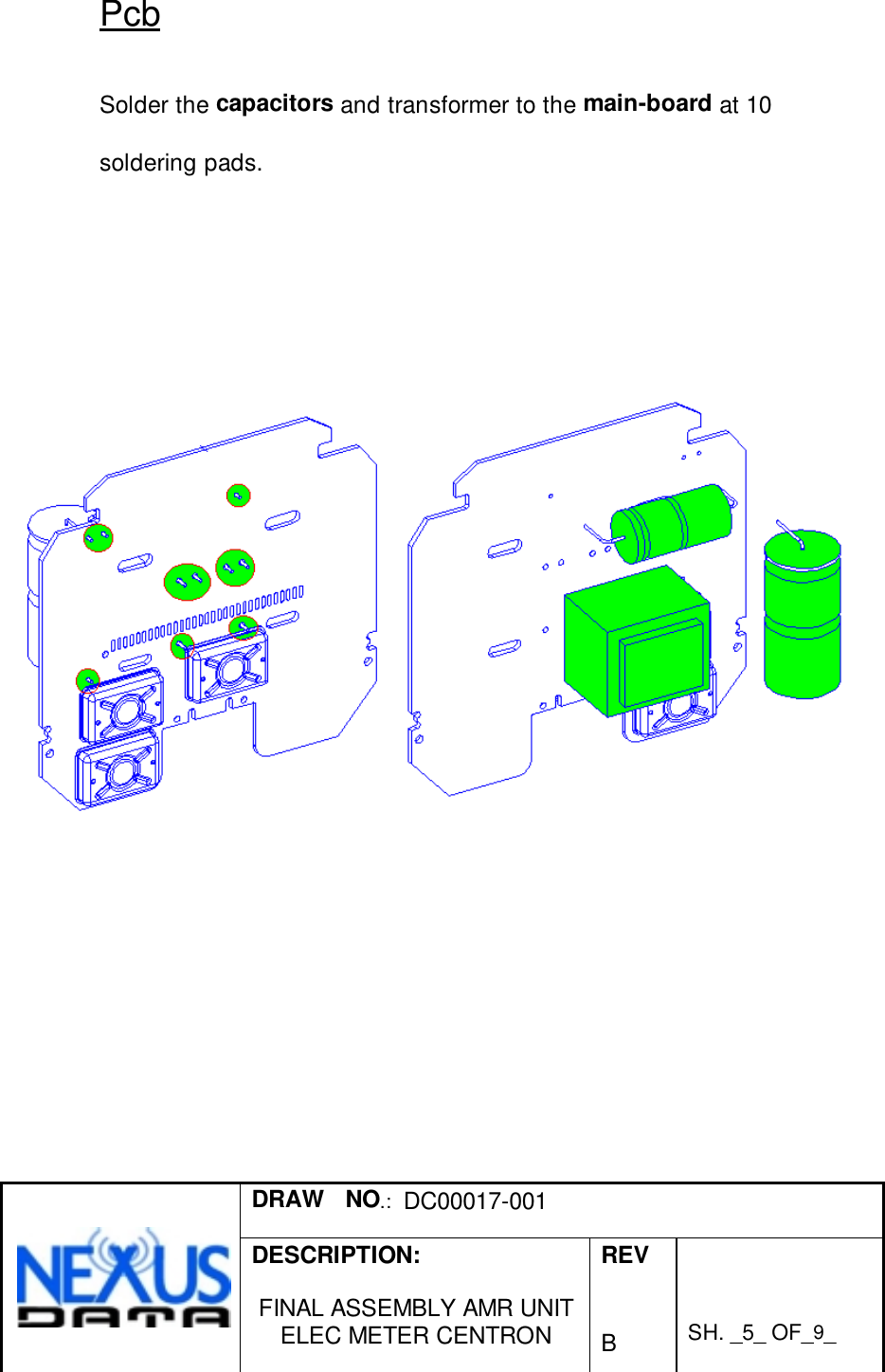
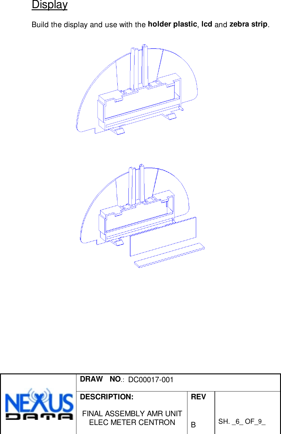
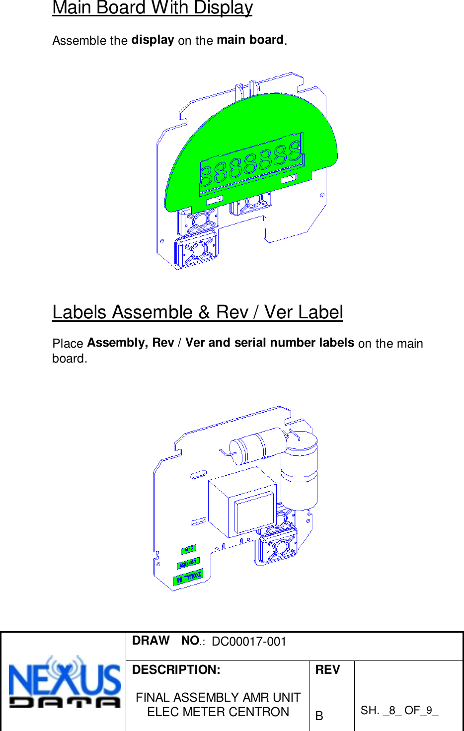
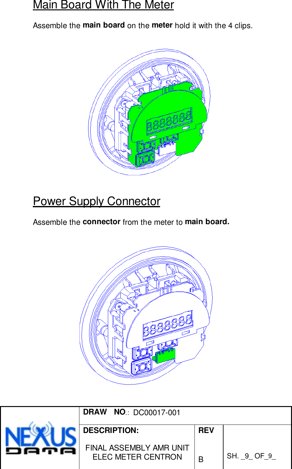
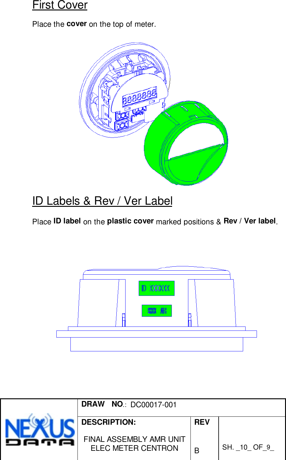
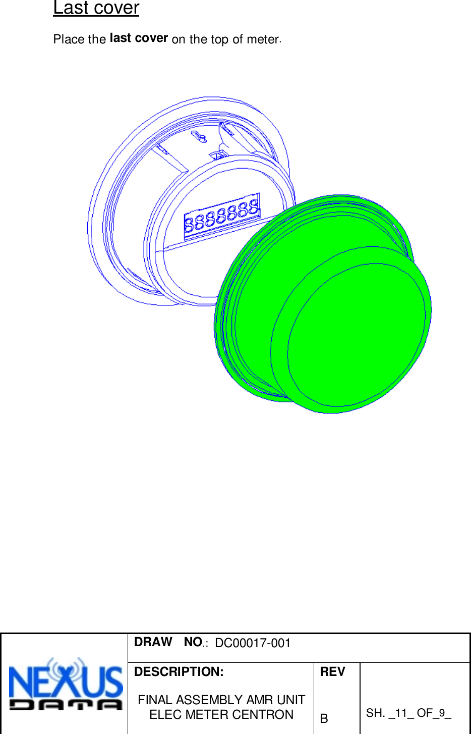
NexusData EL0001 Electric Meter User Manual Revised Installation Guide

NexusData Ltd. Electric Meter Revised Installation Guide

Contents

Revised Installation Guide

REV. ECO No. APPROVED NAME SIGNATUREA First releaseNAME SIGNATURE DATE DESCRIPTION:Product  ManagerR&D Manager FINAL ASSEMBLYTesting AMR UNITManufacturing Eng. Shay Aharon ELEC METER CENTRONQAEngineering Shay AharonSH OF DRAW No. REV.
DRAW   NO.:  DC00017-001DESCRIPTION:FINAL ASSEMBLY AMR UNITELEC METER CENTRONREVBSH. _2_ OF_9_1   DC00017-001 A
DRAW   NO.:  DC00017-001DESCRIPTION:FINAL ASSEMBLY AMR UNITELEC METER CENTRONREVBSH. _3_ OF_9_Table of ContentsMechanical Assembly Description ......................................1Pcb.......................................................................................1Display..................................................................................1Main Board With Display.......................................................1Labels Assemble & Rev / Ver Label......................................1Main Board With The Meter ..................................................1Power Supply Connector.......................................................1First Cover ............................................................................1ID Labels & Rev / Ver Label..................................................1Last cover.............................................................................1
DRAW   NO.:  DC00017-001DESCRIPTION:FINAL ASSEMBLY AMR UNITELEC METER CENTRONREVBSH. _4_ OF_9_Mechanical Assembly DescriptionFCC WarningModifications not expressly approved by the manufacturercould void the user authority to operate the equipment underFCC Rules.In order to comply with FCC RF Exposurerequirements, the AMR unit must be installed in such away that there is a 20 c”m separation distance betweenit and all persons during normal operation.
DRAW   NO.:  DC00017-001DESCRIPTION:FINAL ASSEMBLY AMR UNITELEC METER CENTRONREVBSH. _5_ OF_9_PcbSolder the capacitors and transformer to the main-board at 10soldering pads.
DRAW   NO.:  DC00017-001DESCRIPTION:FINAL ASSEMBLY AMR UNITELEC METER CENTRONREVBSH. _6_ OF_9_DisplayBuild the display and use with the holder plastic, lcd and zebra strip.
DRAW   NO.:  DC00017-001DESCRIPTION:FINAL ASSEMBLY AMR UNITELEC METER CENTRONREVBSH. _7_ OF_9_
DRAW   NO.:  DC00017-001DESCRIPTION:FINAL ASSEMBLY AMR UNITELEC METER CENTRONREVBSH. _8_ OF_9_Main Board With DisplayAssemble the display on the main board.Labels Assemble & Rev / Ver LabelPlace Assembly, Rev / Ver and serial number labels on the mainboard.
DRAW   NO.:  DC00017-001DESCRIPTION:FINAL ASSEMBLY AMR UNITELEC METER CENTRONREVBSH. _9_ OF_9_Main Board With The MeterAssemble the main board on the meter hold it with the 4 clips.Power Supply ConnectorAssemble the connector from the meter to main board.
DRAW   NO.:  DC00017-001DESCRIPTION:FINAL ASSEMBLY AMR UNITELEC METER CENTRONREVBSH. _10_ OF_9_First CoverPlace the cover on the top of meter.ID Labels & Rev / Ver LabelPlace ID label on the plastic cover marked positions & Rev / Ver label.
DRAW   NO.:  DC00017-001DESCRIPTION:FINAL ASSEMBLY AMR UNITELEC METER CENTRONREVBSH. _11_ OF_9_Last coverPlace the last cover on the top of meter.

Navigation menu