NexusData EL0001 Electric Meter User Manual Revised Installation Guide
NexusData Ltd. Electric Meter Revised Installation Guide
Contents
- 1. User Installation Manual
- 2. Revised Installation Guide
Revised Installation Guide
REV. ECO No. APPROVED NAME SIGNATURE
A First release
NAME SIGNATURE DATE DESCRIPTION:
Product Manager
R&D Manager FINAL ASSEMBLY
Testing AMR UNIT
Manufacturing Eng. Shay Aharon ELEC METER CENTRON
QA
Engineering Shay Aharon
SH OF DRAW No. REV.
DRAW NO.: DC00017-001
DESCRIPTION:
FINAL ASSEMBLY AMR UNIT
ELEC METER CENTRON
REV
BSH. _2_ OF_9_
1 DC00017-001 A
DRAW NO.: DC00017-001
DESCRIPTION:
FINAL ASSEMBLY AMR UNIT
ELEC METER CENTRON
REV
BSH. _3_ OF_9_
Table of Contents
Mechanical Assembly Description ......................................1
Pcb.......................................................................................1
Display..................................................................................1
Main Board With Display.......................................................1
Labels Assemble & Rev / Ver Label......................................1
Main Board With The Meter ..................................................1
Power Supply Connector.......................................................1
First Cover ............................................................................1
ID Labels & Rev / Ver Label..................................................1
Last cover.............................................................................1
DRAW NO.: DC00017-001
DESCRIPTION:
FINAL ASSEMBLY AMR UNIT
ELEC METER CENTRON
REV
BSH. _4_ OF_9_
Mechanical Assembly Description
FCC Warning
Modifications not expressly approved by the manufacturer
could void the user authority to operate the equipment under
FCC Rules.
In order to comply with FCC RF Exposure
requirements, the AMR unit must be installed in such a
way that there is a 20 c”m separation distance between
it and all persons during normal operation.
DRAW NO.: DC00017-001
DESCRIPTION:
FINAL ASSEMBLY AMR UNIT
ELEC METER CENTRON
REV
BSH. _5_ OF_9_
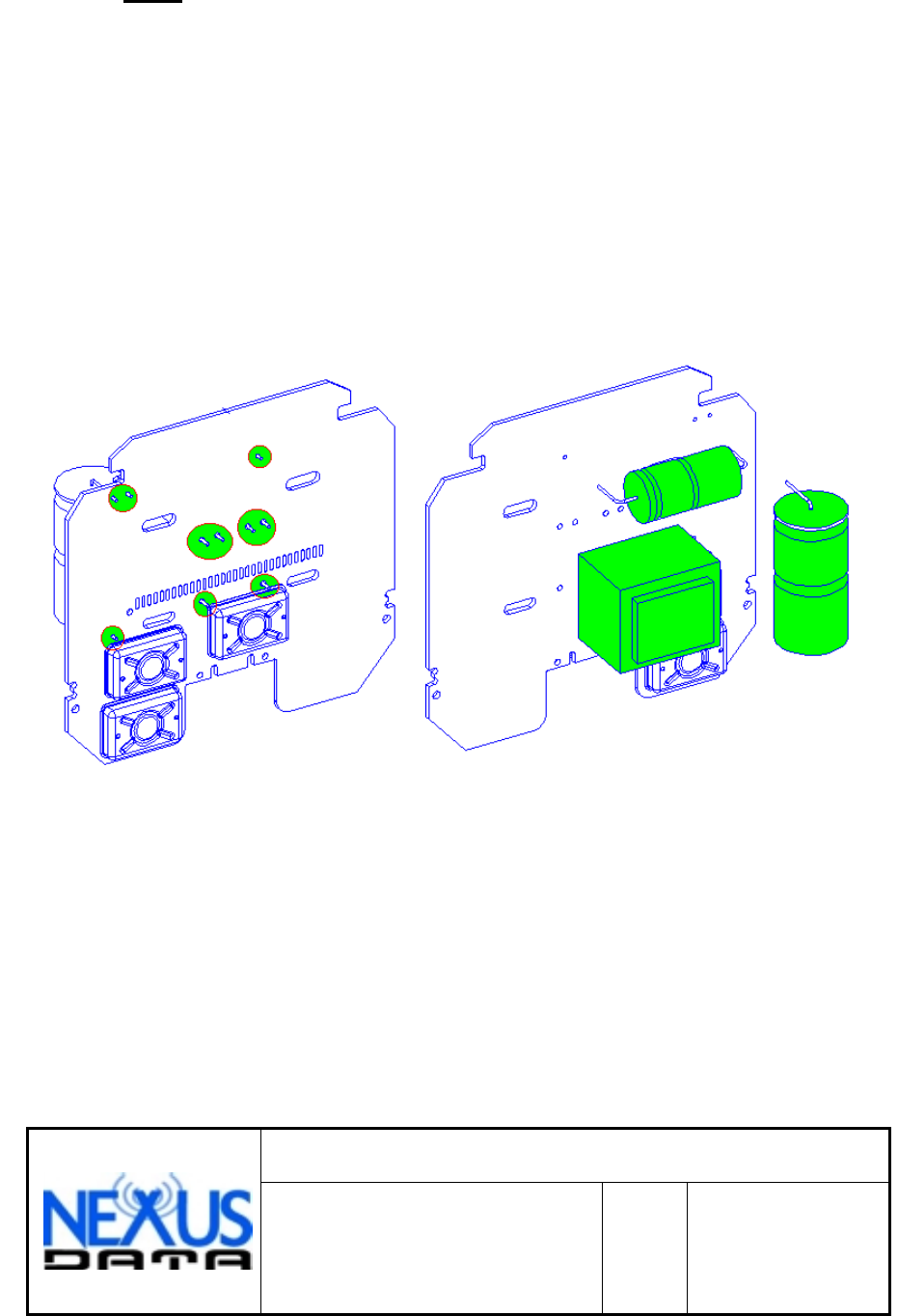
Pcb
Solder the capacitors and transformer to the main-board at 10
soldering pads.
DRAW NO.: DC00017-001
DESCRIPTION:
FINAL ASSEMBLY AMR UNIT
ELEC METER CENTRON
REV
BSH. _6_ OF_9_
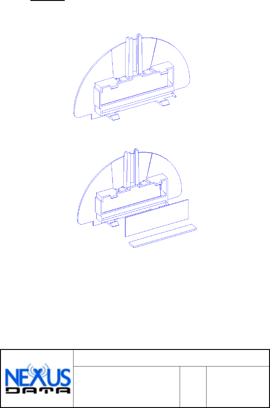
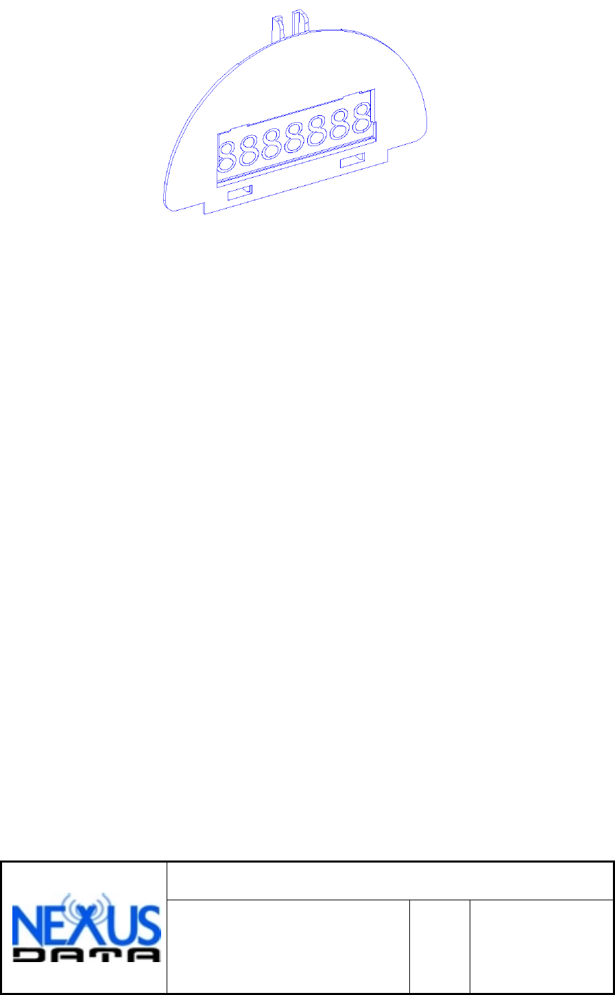
Display
Build the display and use with the holder plastic, lcd and zebra strip.
DRAW NO.: DC00017-001
DESCRIPTION:
FINAL ASSEMBLY AMR UNIT
ELEC METER CENTRON
REV
BSH. _7_ OF_9_
DRAW NO.: DC00017-001
DESCRIPTION:
FINAL ASSEMBLY AMR UNIT
ELEC METER CENTRON
REV
BSH. _8_ OF_9_
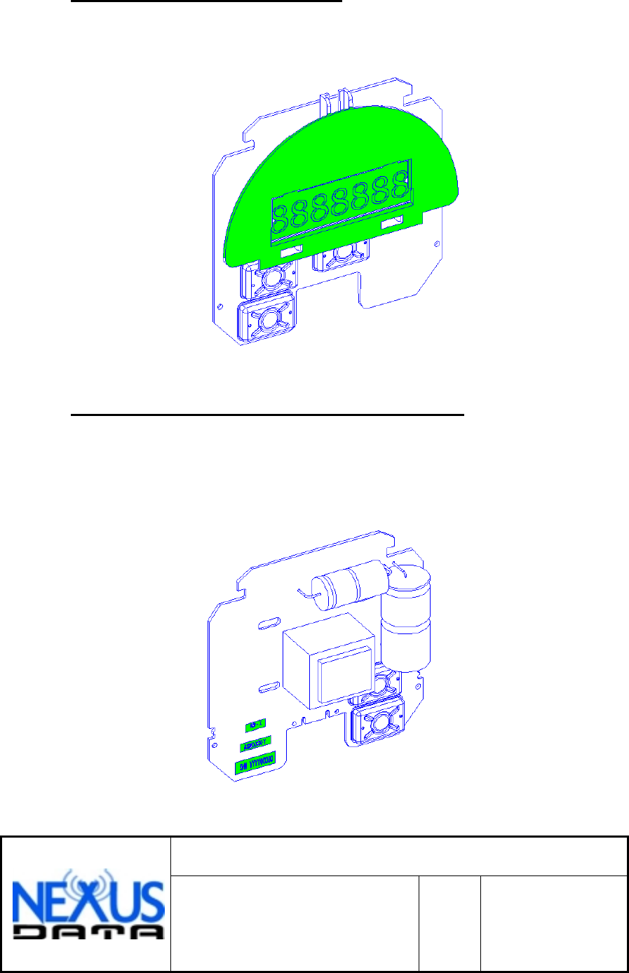
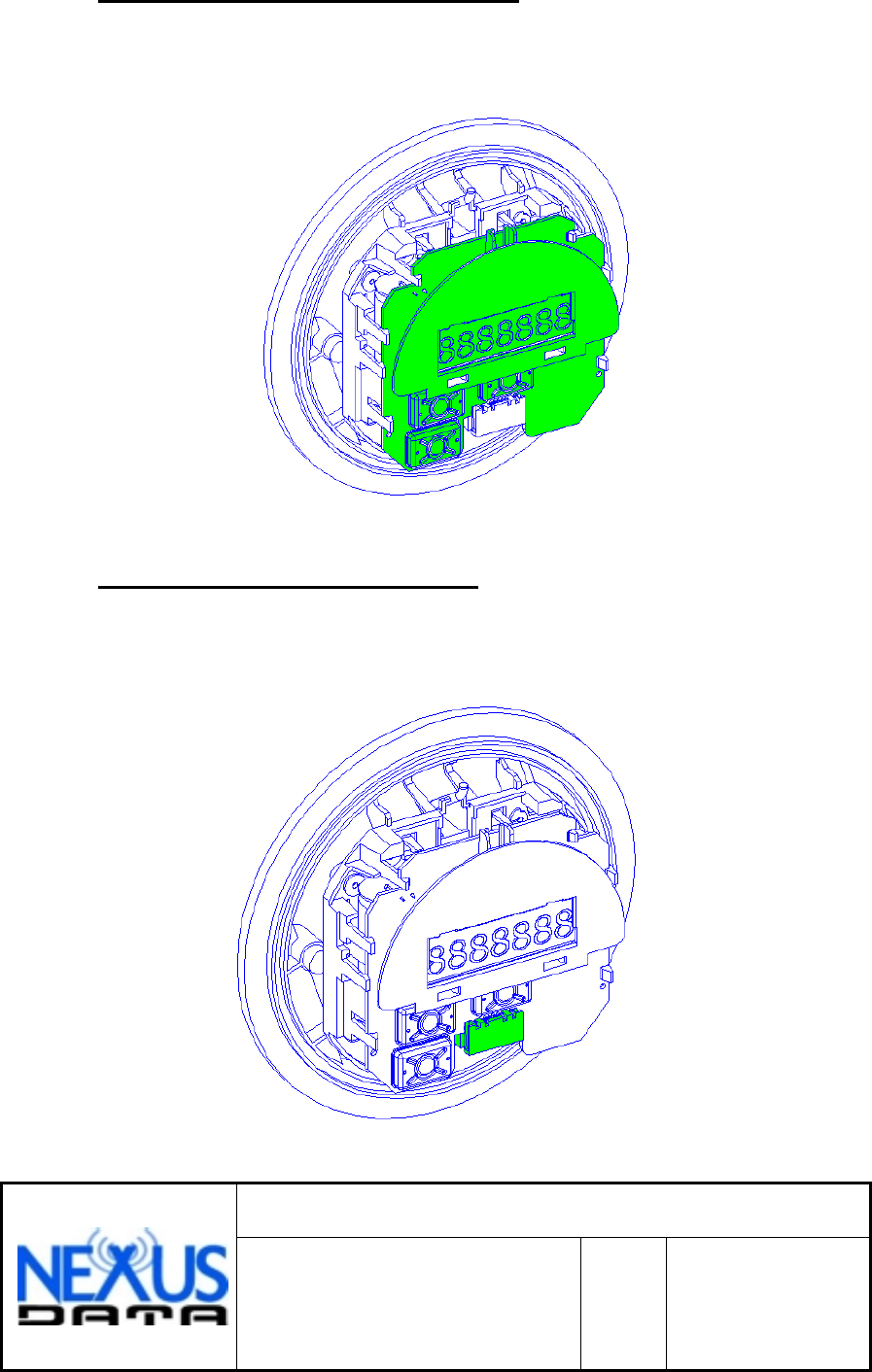
Main Board With Display
Assemble the display on the main board.
Labels Assemble & Rev / Ver Label
Place Assembly, Rev / Ver and serial number labels on the main
board.
DRAW NO.: DC00017-001
DESCRIPTION:
FINAL ASSEMBLY AMR UNIT
ELEC METER CENTRON
REV
BSH. _9_ OF_9_
Main Board With The Meter
Assemble the main board on the meter hold it with the 4 clips.
Power Supply Connector
Assemble the connector from the meter to main board.
DRAW NO.: DC00017-001
DESCRIPTION:
FINAL ASSEMBLY AMR UNIT
ELEC METER CENTRON
REV
BSH. _10_ OF_9_
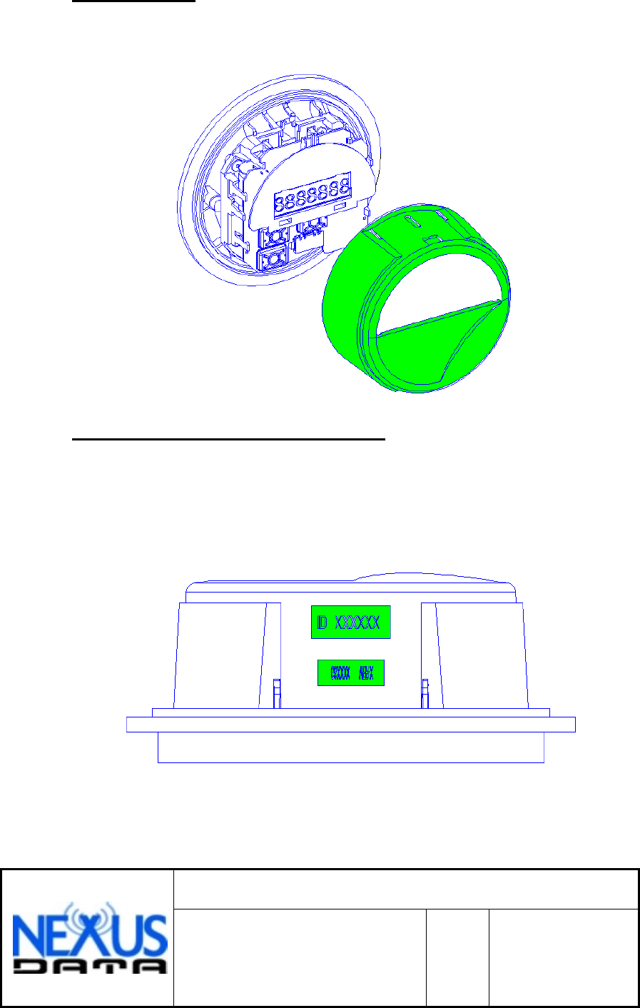
First Cover
Place the cover on the top of meter.
ID Labels & Rev / Ver Label
Place ID label on the plastic cover marked positions & Rev / Ver label.
DRAW NO.: DC00017-001
DESCRIPTION:
FINAL ASSEMBLY AMR UNIT
ELEC METER CENTRON
REV
BSH. _11_ OF_9_
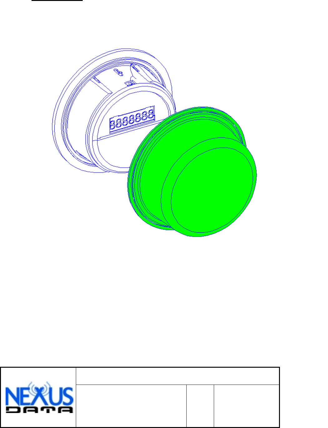
Last cover
Place the last cover on the top of meter.