Nice S p A 433A08 Receiver User Manual Nice Neomat H 89 027 rev0
Nice S.p.A. Receiver Nice Neomat H 89 027 rev0
Contents
- 1. leaflet
- 2. User Manual
User Manual

neomat H
tubular motor
Instrukcje i uwagi dla instalatora
Istruzioni ed avvertenze per l’installatore
Instructions and warnings for the fitter
Instructions et recommandations pour l’installateur
Anweisungen und Hinweise für den Installateur
Instrucciones y advertencias para el instalador

2
Warnings:
Warning: it is important that you comply with these instruc-
tions for your own and other people’s safety.
Store this manual in a safe place for future reference.
This manual contains important safety provisions; incorrect
installation may create serious hazards.
The “NEOMAT H” series motors have been designed for the automation
of awnings; any other use is considered improper and is prohibited.
These motors are intended for residential use. Maximum continuous
operating time is 4 minutes with a 20% cycle.
When selecting the type of motor based on the application, you should
consider the nominal torque and the operating time shown on the rating
plate. The minimum diameter of the tube in which the motor can be
installed is 52 mm for NEOMAT MH and 70 mm for NEOMAT LH.
The motor must be installed by qualified personnel in compliance with
current safety regulations, especially as regards the electrical connec-
tions. Minimum installation height is 2.5 m from the ground or floor.
Easy access must in any case be ensured. The horizontal clearance
between the fully open awning and any stationary object must be at least
0.4 m. As regards units for outdoor use, the power supply cable must
be installed inside a protective duct.
The tubular motor must not be subjected to crushing, impacts, falls or
contact with any kind of liquid.
Do not perforate or drive screws into any part of the tubular motor (fig. 1).
For maintenance and repairs contact a qualified technician.
The application must be visible from the control buttons, which must be
positioned away from any moving parts, at a height of at least 1.5 m off
the ground. Keep people away from the awning when the latter is in
motion. If any work, such as window cleaning, is being carried out near
the awning, do not operate it; in case of automatic control, disconnect
the power supply as well.
Do not allow children to play with the controls and keep all remote con-
trols away from their reach.
The NEOMAT MH Ø45mm and NEOMAT LH Ø58mm tubular motors
(fig. 2) feature an electronic control unit with incorporated radio
receiver, operating at a frequency of 433.92 MHz, with rolling code
technology, to guarantee high levels of security. Up to 14 “ERGO”
and “PLANO” series radio controls (fig. 3) or radio-sensors can be
memorised for each motor, e.g. “VOLO S RADIO” (fig. 3).
The control unit incorporated in the motor features a high precision
electronic limit switch system capable of continuously monitoring the
position of the awning. The range of movement, i.e. the closed/open
positions (plus any intermediate positions) can be programmed and
memorised; after each command, the movement stops automatical-
ly when these positions are reached. The electronic limit switch can
compensate for any stretching of the fabric (“CAT” function), guar-
anteeing the perfect closure of the shutter box and preventing any
slack in the fabric when the awning is open. The NEOMAT H motors
can be programmed for “RDC” torque reduction, a function that
decreases motor torque by approximately 50% just before the
awning closes completely to prevent excessive stretching of the fab-
ric. NEOMAT H also features an “RDT” draw release function that
reduces the stretch of the fabric momentarily after the closing oper-
ation has been completed, to prevent prolonged stretching.
The CAT, RDC and RDT functions have been especially studied to
simulate the careful and meticulous behaviour of a person who
opens and closes the awning manually.
The range of movement and a few additional functions can be pro-
grammed through the radio controls. A beep will sound to guide the
various phases. The motors can only be controlled via radio, though
the awning can also be moved using the “emergency manoeuvre”
feature. The movement of the awning can be automated based on
the weather conditions by using optional wind, sun and rain sensors,
such as “VOLO S RADIO”.
1) Product description
NEOMAT H is produced by Motus S.p.a. (TV) I. ERGO, PLANO, VOLO S RADIO are produced by Nice S.p.a.(TV) I. Motus S.p.a. is an affiliate of the Nice S.p.a group.
1.1) Emergency manoeuvre
The NEOMAT H tubular motors are equipped with an emergency
manoeuvre feature.
The emergency manoeuvre is a mechanism that enables the manu-
al movement of the awning, for instance when a power failure
occurs. It is activated by rotating the rod located on the motor’s head
in the required direction.
When the emergency manoeuvre is used, or if the motor is left with-
out electric power for over 24 hours, the motor control unit loses the
value of the current position of the awning. To correct this situation,
an automatic realignment feature is provided: just carry out an Up
manoeuvre until the awning is completely wound up. If you com-
mand a Down manoeuvre before realignment, the movement will
take place in “man present” mode (i.e. the awning will move while the
command is active).
GB
3
2) Installation
Proceed as follows to prepare the motor (fig. 4):
1. Position the ring gear (E) on the motor (A) until it fits into the
corresponding ring nut (F).
2. Mount the draw adapter (D) on the motor shaft.
3. On NEOMAT H, fasten the draw adapter with the snap ring.
Figure 4
A: NEOMAT H tubular motor
B: Fixing clips, cotter pins or screws
C: Support and spacer
D: Draw adapter
E: Ring gear
F: Ring nut
G: Rod for emergency manoeuvre
The NEOMAT H series tubular motors are equipped with an elec-
tronic limit switch system. The electronic control unit interrupts the
movement when the awning reaches the programmed open or
closed positions. These positions must be programmed into the
memory after the motor has been installed and the awning has been
fully mounted. The motor can still be controlled even if these two
positions, “0” (awning closed) and “1” (awning open), have not yet
been memorised; however, the movement in this case must be con-
trolled manually. It is also possible to program an intermediate posi-
tion (Pos. “I”) for partial opening of the awning.
If intermediate position “I” has been memorized, the awning can be
moved to the programmed position by pressing the 2 buttons ▼▲
on the transmitter simultaneously.
The “I” position and the activation of the torque reduction function
(RDC) can also be programmed at a later time.
3) Adjustments
Fit the assembled motor into the awning’s winding tube until it touch-
es the end of the ring gear (E).
Fasten the tube to the draw adapter (D) using the M4x10 screw in
order to prevent the motor from slipping or sliding axially (fig. 6).
Finally, secure the motor head to the special support (C) with the
clips, cotter pins or screws. (B).
A rod can be inserted in the head of the motor to enable movement
under emergency conditions (emergency manoeuvre).
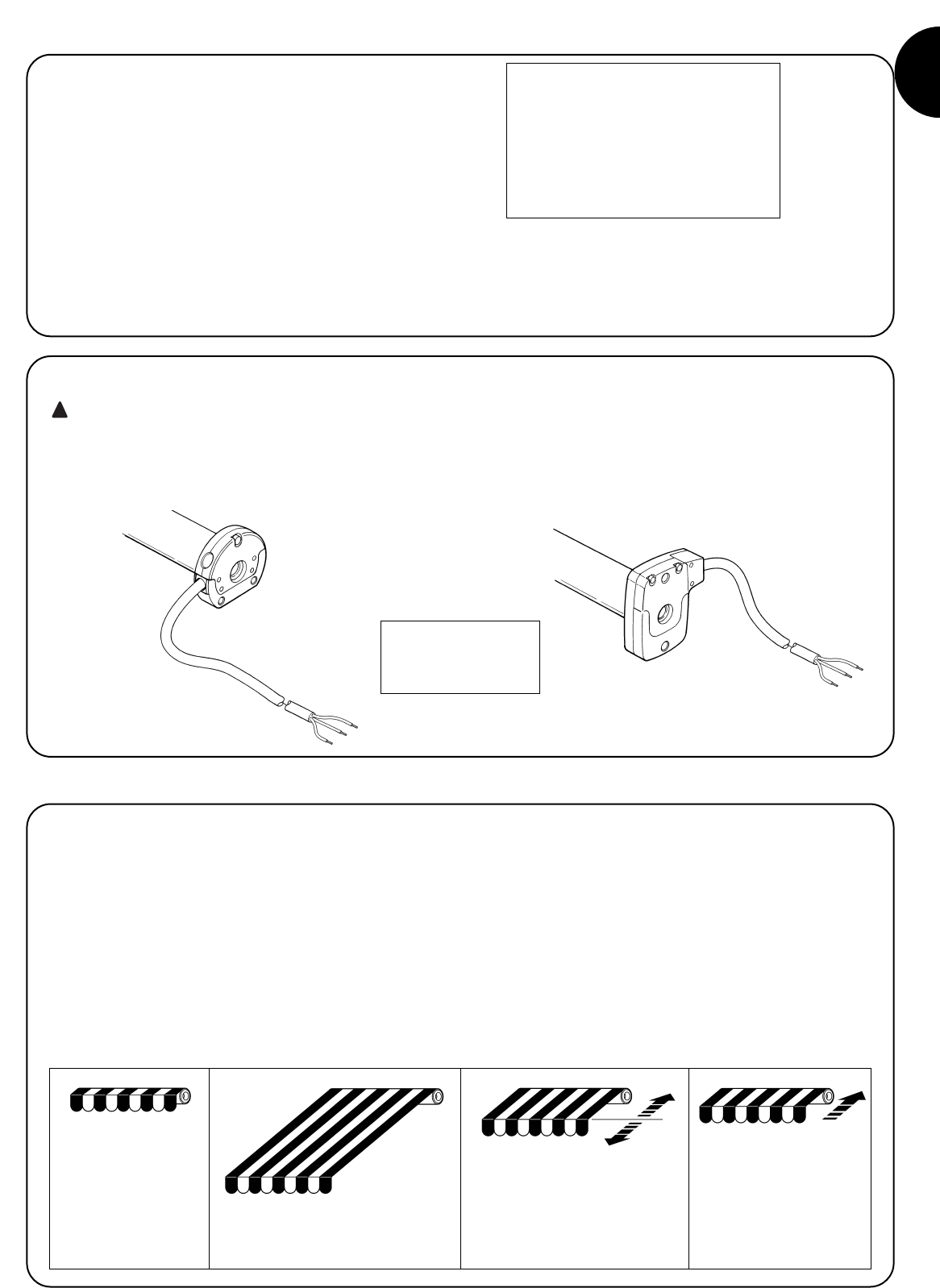
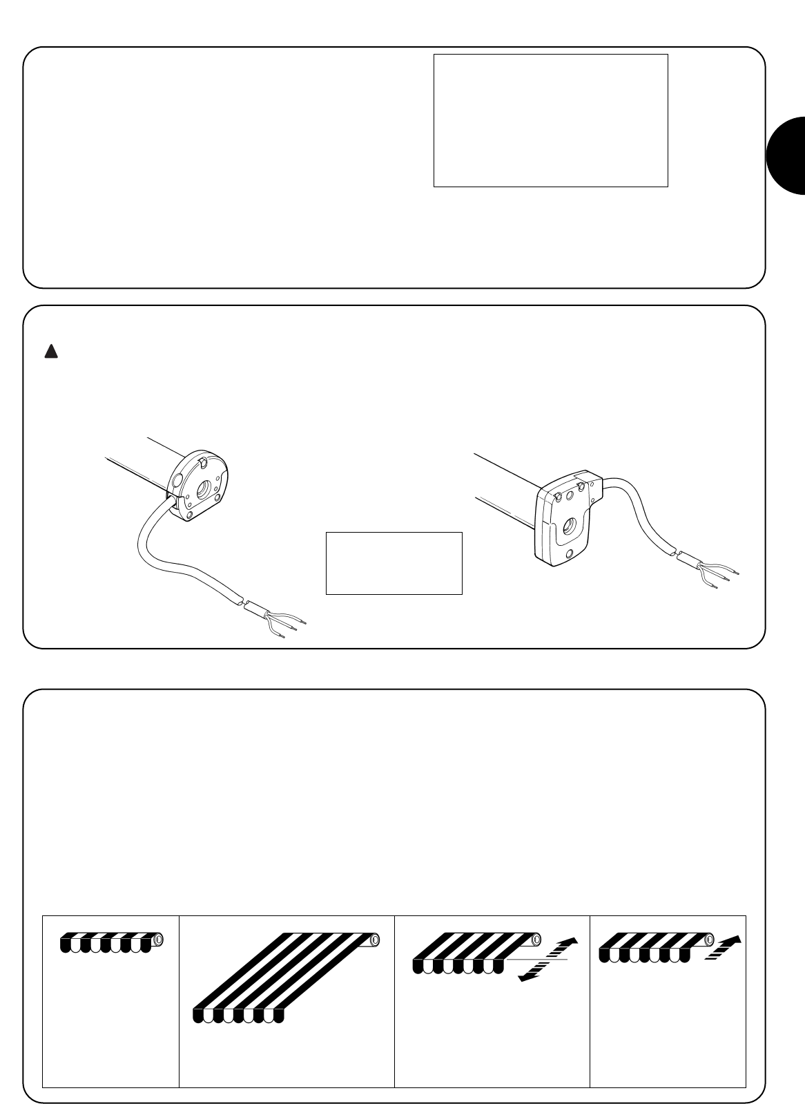
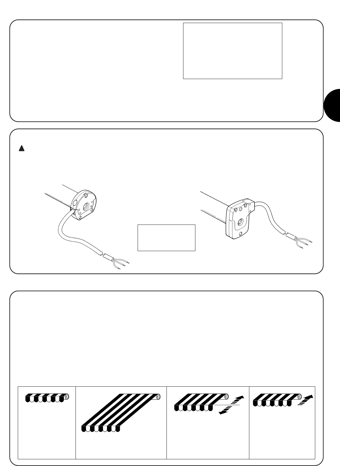
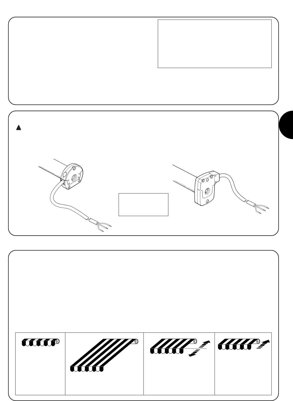
2.1) Electrical connections
WARNING: For motor connections, an omnipolar dis-
connecting device with a 3-mm minimum distance
between contacts must be provided for disconnection
from the mains power supply (disconnecting switch or
plug and socket, etc.).
The cable used for the electrical connections of the NEOMAT H
motor has 3 wires:
•Phase, Neutral and Earth.
Make sure that the mains voltage corresponds to the ratings of
NEOMAT H.
!
Awning fully closed
(Pos. “0”)
Intermediate position (“I”)
RDC torque reduction start
position in the closing
manoeuvre
Awning open (Pos.”1”)
Brown = Phase
Blue = Neutral
Yellow/Green = Earth

4
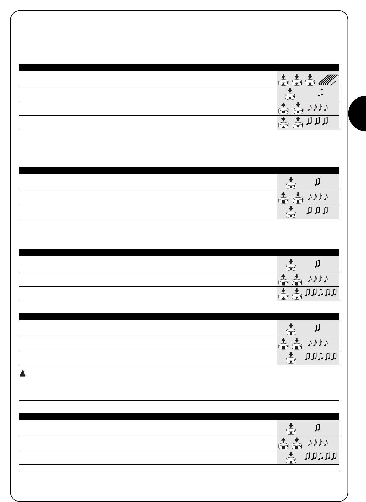
Programming is divided into three stages:
1. Memorising the transmitters
2. Programming the “0” and “1” positions
3. Optional programming
WARNING: All the transmitter memorisation and para-
meter programming sequences are timed, i.e. they must
be carried out within set time limits.
•For radio controls designed to handle multiple “units”,
before proceeding with the memorisation you need to
select the unit to which the motor should be associated.
•All the motors within the range of the transmitter can be
programmed by radio; therefore, only the motor involved
in the operation should be kept switched on.
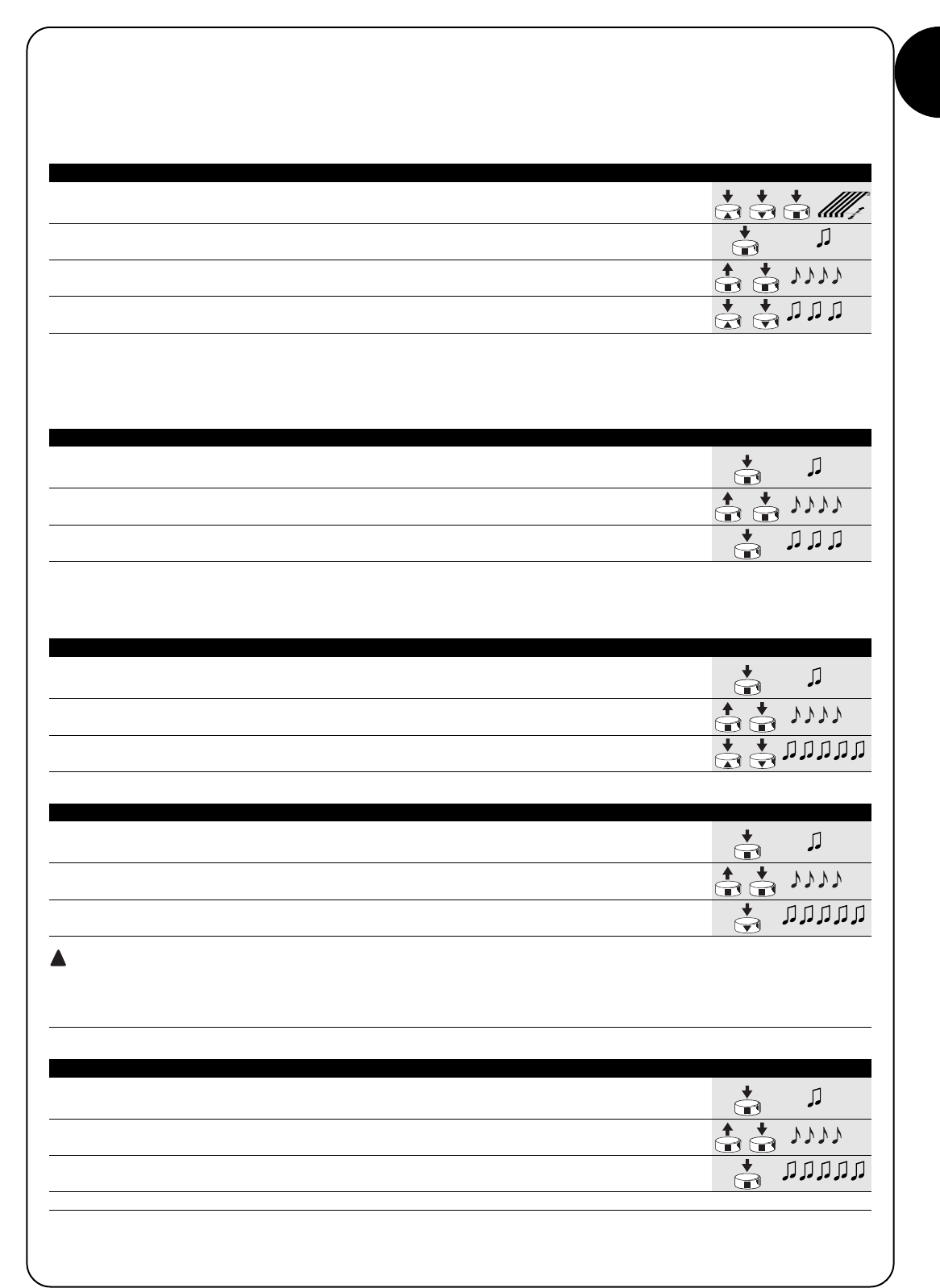
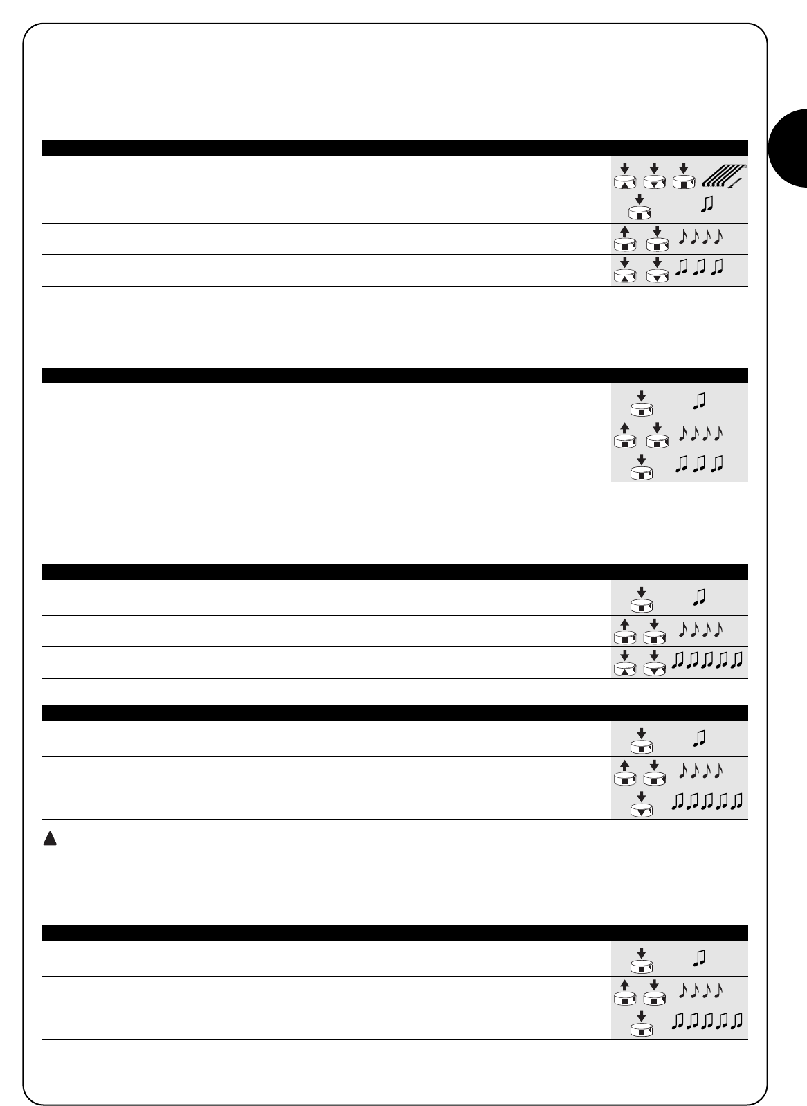
4) Programming
1. Press and hold down key ▲or ▼on a memorised remote control until the closing of the
awning is complete and the motor has stopped automatically.
2. Press and hold down key ▼to lower the awning.
3. Release key ▼ when the awning has reached the desired position (“1”).
If necessary, adjust the position using keys ▼ and ▲.
4. Press and hold down key ■on the transmitter until you hear a beep (approx. 5 seconds).
5s
5. Release and then press again key ■for 5 more seconds until you hear 4 short beeps.
5s
6. Press and hold down key ▼until 3 beeps and a brief up and down movement signal that
the position has been memorised.
Table “A3” Programming the “0” and “1” positions (fig. 9) Example
4.1) Memorising the transmitters
Each radio control is recognised by the receiver incorporated in the NEOMAT H control unit through an individual “code” that is unlike any
other. The control unit must therefore be programmed to recognise each separate radio control through a “memorisation” process.
When the memory does not contain any code, you can proceed to program the first radio control by operating as follows:
!
1. When the control unit is switched on, you will hear two long beeps.
2. Within 5 seconds, press and hold down (for approx. 3 seconds) key ■on the transmitter
that must be memorised. 3s
3. When you hear the first of the 3 beeps confirming the memorisation, release key ■
Note: If the control unit already contains codes, 2 short beeps will be heard when it is switched on. In this case you cannot proceed as
described above but must use the other memorisation method (Table “A2”)
Table “A1” Memorising the first transmitter (fig. 7) Example
1. Press and hold down (approx. 5 seconds) key ■on the new transmitter until you hear
the beep. New 5s
2. Slowly press key ■on a previously enabled (old) transmitter 3 times.
Old X3
3. Press again key ■on the new transmitter.
New
4. Finally, 3 beeps will signal that the new transmitter has been correctly memorised.
Note: If the memory is already full (14 codes), 6 beeps will indicate that the transmitter cannot be memorised.
Table “A2” Memorising additional transmitters (fig. 8) Example
When one or more transmitters have already been memorised, additional ones can be enabled by proceeding as follows:
4.2) Programming the “0” and “1” positions
To program the positions you need to use a previously memorised remote control. Unless the “0” and “1” positions have been memorised in
the control unit, the movements require manual control. Initially the direction of the motor is not defined, but when step 1 in table “A3” has
been executed, the direction of the motor will be automatically assigned to the remote control keys.
To program positions 0 and 1 proceed as follows:
GB
5
1. Using keys ▲ or ▼and ■on a remote control, move the awning to the position that
you wish to memorise as “I”.
2. Press and hold down (approx. 5 seconds) key ■until you hear the beep.
5s
3. Release and then press again key ■for 5 more seconds until you hear 4 short beeps.
5s
4. Press keys ▲ and ▼simultaneously until 3 beeps signal that the position has
been memorised.
Table “A4” Programming the intermediate position “I” (fig. 10) Example
4.3) Optional programming
Optional programming operations can only be performed after the “0” and “1” positions have been programmed
4.3.1) Memorising the intermediate position “I”
To memorise the intermediate position proceed as follows:
1. Press and hold down key ■on a previously memorised transmitter until you hear a beep
(approx. 5 seconds). 5s
2. Release and then press again key ■for 5 more seconds until you hear 4 short beeps.
5s
3. Press key ■until 3 beeps signal that the RDC function has been activated.
Table “A5” Programming the RDC torque reduction function (fig 11) Example
4.3.2) Programming RDC torque reduction during the closing operation
Torque reduction is a programmable function that decreases motor torque by approximately 50% just before the awning closes completely,
to prevent excessive stretching of the fabric.
1. Press and hold down key ■on a previously memorised transmitter until you hear a beep
(approx. 5 seconds). 5s
2. Release and then press again key ■for 5 more seconds until you hear 4 short beeps.
5s
3. Press keys ▲ and ▼simultaneously until 5 beeps signal that the intermediate position
has been erased.
Table “A6” Erasing intermediate position “I” (fig. 10) Example
4.3.3) Erasing the positions or the RDC function
To modify the previously memorised positions, first you need to erase them, then you must reprogram the new positions.
1. Press and hold down key ■on a previously memorised transmitter until you hear a beep
(approx. 5 seconds). 5s
2. Release and then press again key ■for 5 more seconds until you hear 4 short beeps.
5s
3. Press key ▼until 5 beeps signal that positions “0” and “1” has been erased.
WARNING: After positions “0” and “1” have been erased, the awning will only move by manual control, therefore a
new position must be memorised.
Note: if you have programmed an intermediate position “I” and the RDC function, these will not be erased. If you wish to erase all (including
the transmitter codes) see table “A9.”
Table “A7” Erasing positions “0” and “1” (fig. 12) Example
1. Press and hold down key ■on a previously memorised transmitter until you hear a beep
(approx. 5 seconds). 5s
2. Release and then press again key ■for 5 more seconds until you hear 4 short beeps.
5s
3. Press key ■until 5 beeps signal that the RDC function has been deactivated.
Note: Now the awning will close at full power
Table “A8” Erasing the RDC torque reduction function (fig. 11) Example
!
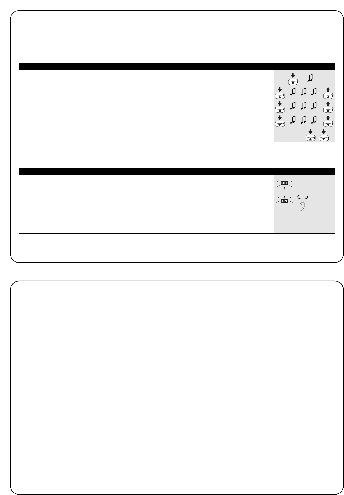
6
1. Press and hold down button ■of a transmitter until you hear a beep
(after about 5 seconds) 5s
2. Press and hold down key ▲on the transmitter until you hear 3 beeps; release key ▲
exactly during the third beep. 5s
3. Press and hold down key ■on the transmitter until you hear 3 beeps; release key ■
exactly during the third beep.
4. Press and hold down key ▼on the transmitter until you hear 3 beeps; release key ▼
exactly during the third beep.
5. If you wish to erase all the data, press the ▲and ▼ keys together within 2 seconds and
then release them. within 2 s
After a few seconds 5 beeps will signal that all the memorised codes have been erased.
Table “A9” Erasing the memory with a previously memorized transmitter (fig. 13) Example
If you need to erase all the data contained in the memory of the con-
trol unit in the NEOMAT H motors, carry out the following procedure.
The memory can be erased:
•with a previously memorised transmitter (table “A9”)
•with a non-memorised transmitter (table “A10”).
The following can be erased:
•only the transmitter codes, finishing at point N. 4
•all the data (transmitter codes, positions, RDC function, etc.), com-
pleting the procedure.
➨
When the motor is switched on, the 2 beeps do not sound.
Make sure the motor is powered with the correct voltage; if the pow-
er input is correct there is probably a serious fault and the motor
needs replacing.
After a radio command, 6 beeps are heard and the
manoeuvre does not start
The radio control unit is unsynchronised, repeat the transmitter
memorisation process.
After a command, 10 Beeps sound and then the manoeu-
vre begins
The auto-diagnosis of the memorised parameters has detected a
fault (positions, programming, direction of movement are incorrect).
Check and repeat programming if necessary.
After a command the motor does not turn.
•The thermal protection might have triggered; in this case just wait
for the motor to cool down
•∑If a wind sensor has been memorized, the set threshold might
have been exceeded.
•You might try to switch the motor off and back on again; if the 2
beeps do not sound, there is probably a serious fault and the
motor needs replacing.
During the UP phase, before reaching the set position
(pos. “0”, pos. “I”), the motor stops and then makes 3
attempts to start up again.
This does not necessarily mean trouble: in case of overload during
the UP phase the motor is switched off for 1 second and then
attempts to complete the manoeuvre. Check to see if any obstacles
are obstructing movement.
During the DOWN phase, before reaching the set position
(pos. “1”, pos. “I”), the motor stops.
This does not necessarily mean trouble: in case of overload the
motor is switched off. Check to see if any obstacles are obstructing
movement.
The motor turns only if the control is manned.
If positions “0” and “1” have not been programmed the motor rolls
the awning up or down only through manual control. Program posi-
tions “0” and “1”.
Positions “0” and “1” have been programmed, but the
awning moves down only if the control is manned.
The emergency manoeuvre has probably been used, or the motor
has remained switched off for over 24 hours. Give the command to
raise the awning and wait for it to reach position “0”.
5) What to do if… a small troubleshooting guide!
In order to erase the memory using a non-memorized remote control, proceed as follows:
If the application requires it, the awning can be automated using the VOLO S RADIO wind and sun sensor. This sensor, when properly memo-
rised in the motor, will ensure that the awning is extended when the sun is shining and that it is retracted when the wind rises. For a detai-
led description of the performances and programming of the sensor levels refer to the instructions for the VOLO S RADIO product.
1. Switch off the power supply for at least 3 seconds.
3s
2. Switch the power back on and within 10 seconds rotate the rod for emergency manoeuvre X6
device for at least 6 turns.
within 10s
3. At this point, within 1 minute, you can proceed to erase the memory following the procedure
described in table “A9”, using any remote control, even a non-memorized one. “Table A9”
Table “A10” Erasing the memory with a non-memorized transmitter (fig. 14) Example

GB
7
6) Technical characteristics
NEOMAT H series tubular motors
Supply voltage and frequency : See the technical data on the label attached to each model
Current and power : See the technical data on the label attached to each model
Torque and speed : See the technical data on the label attached to each model
Continuous operating time : Maximum 4 minutes
Work cycle : Maximum 20%
Protection class : IP 44
Operating temperature : -10 ÷ 50 °C
Precision (resolution) of the electronic limit switch : Greater than 0.55° (depending on the NEOMAT H version)
Duration of position memory in the absence of power supply : Longer than 24 hours
(with automatic realignment upon the first UP manoeuvre)
Radio receiver
Frequency : 433.92 MHz
Coding : 52 Bit rolling code FLOR
Range of ERGO and PLANO transmitters : Estimated at 100-200 m in the open and under optimum conditions,
and 20-30 m inside buildings
Range of VOLO S RADIO transmitters : Estimated at 100-200 m in the open and under optimum conditions
Nice S.p.a. reserves the right to modify its products at any time without notice.

88
Avvertenze:
Attenzione: per la sicurezza delle persone è importante
rispettare queste istruzioni.
Conservare questo manuale per poterlo consultare in futuro.
Il presente manuale contiene importanti disposizioni per la
sicurezza, installazioni non corrette possono creare gravi
situazioni di pericolo.
I motori serie “NEOMAT H” sono stati realizzati per automatizzare il
movimento di tende da sole; ogni altro uso è improprio e vietato. I moto-
ri sono progettati per uso residenziale; è previsto un tempo di lavoro
continuo massimo di 4 minuti con un ciclo del 20%. Nella scelta del tipo
di motore in funzione dell’applicazione, si dovrà considerare la coppia
nominale ed il tempo di funzionamento riportato sui dati targa. Il diame-
tro minimo del tubo in cui il motore può essere installato è 52mm per
NEOMAT MH e 70mm per NEOMAT LH. L’installazione deve essere ese-
guita da personale tecnico nel pieno rispetto delle norme di sicurezza,
soprattutto per quanto riguarda i collegamenti elettrici.
L’altezza di installazione minima è 2,5 m da terra o dal pavimento, garan-
tendo comunque un facile accesso; la distanza in orizzontale tra la ten-
da completamente aperta e qualsiasi oggetto permanente deve essere
garantita ad almeno 0,4m. Per gli apparecchi ad uso esterno, il cavo di
alimentazione deve essere installato dentro un condotto di protezione.
Non sottoporre il motore tubolare a schiacciamenti, urti, cadute o con-
tatto con liquidi di qualunque natura; non forare né applicare viti per tut-
ta la lunghezza del tubolare (fig. 1). Rivolgersi a personale tecnico com-
petente per manutenzioni e riparazioni.
I pulsanti di comando devono essere a vista dell’applicazione ma distan-
ti dalle parti in movimento e ad un’altezza di almeno 1,5m. Mantenere le
persone distanti dalla tenda quando è in movimento. Non azionare la
tenda se nelle vicinanze vengono eseguiti dei lavori, ad esempio: pulizia
vetri; nel caso di comando automatico, scollegate anche l’alimentazione
elettrica. Non permettere ai bambini di giocare con i comandi e tenere
lontano da loro i telecomandi.
I motori tubolari NEOMAT MH Ø45mm e NEOMAT LH Ø58mm (fig.
2) contengono una centrale elettronica con ricevitore radio incorpo-
rato che opera alla frequenza di 433.92 MHz con tecnologia rolling
code, per garantire elevati livelli di sicurezza.
Per ogni motore è possibile memorizzare fino a 14 radiocomandi del-
la serie “ERGO” e “PLANO” (fig. 3) o radio-sensori, ad esempio
“VOLO S RADIO” (fig. 3).
La centrale incorporata nel motore dispone di un sistema di finecor-
sa elettronico ad elevata precisione che è in grado di rilevare costan-
temente la posizione della tenda. Attraverso un’operazione di pro-
grammazione vengono memorizzati i limiti del movimento, cioè ten-
da chiusa e tenda aperta (più eventuali posizioni intermedie); dopo
ogni comando il movimento si fermerà automaticamente al raggiun-
gimento di queste posizioni. Il finecorsa elettronico è in grado di
compensare eventuali allungamenti del telo (funzione “CAT”) garan-
tendo la chiusura perfetta del cassonetto ed evitando allentamenti
del telo quand’è aperto. I motori NEOMAT H possono essere pro-
grammati per attivare la riduzione di coppia (funzione “RDC”) che
diminuisce del 50% circa la coppia del motore poco prima che la
tenda sia completamente chiusa per evitare di tirare eccessivamen-
te il telo.
NEOMAT H prevede inoltre la funzione “RDT” di rilascio della trazio-
ne che allenta brevemente la tensione sul telo dopo aver terminato
la manovra di chiusura, in modo che il telo non rimanga troppo teso
per lunghi periodi. Le funzioni CAT, RDC e RDT sono state studiate
per simulare il comportamento attento e diligente di una persona che
muove manualmente la tenda.
La programmazione dei limiti di movimento e di alcune funzioni
aggiuntive è eseguibile dai radiocomandi, un “Bip” acustico ne gui-
derà le varie fasi. I motori possono essere comandati solo tramite
radiocomando o in alternativa si può muovere la tenda mediante l’u-
tilizzo della “manovra di soccorso”. Il movimento della tenda può
essere automatizzato in funzione delle condizioni climatiche median-
te l’utilizzo dei sensori radio opzionali di vento, sole, pioggia ad
esempio “VOLO S RADIO”.
1) Descrizione del prodotto
NEOMAT H è prodotto da Motus S.p.a. (TV) I. ERGO, PLANO, VOLO S RADIO sono prodotti da Nice S.p.a.(TV) I. Motus S.p.a. è una società del gruppo Nice S.p.a.
1.1) Manovra di soccorso
I motori tubolari NEOMAT H dispongono di manovra di soccorso.
La manovra di soccorso è un meccanismo che permette di muove-
re la tenda manualmente, ad esempio quando manca l’energia elet-
trica. Si utilizza attraverso l’astina collocata nella testa del motore,
ruotandola in un senso oppure nell’altro.
Quando viene usata la manovra di soccorso, oppure se il motore
rimane senza energia elettrica oltre 24 ore, la centrale di comando
del motore perde il valore della posizione attuale della tenda. In que-
sta situazione è prevista una fase di riallineamento automatico, basta
effettuare una manovra di salita fino al completo riavvolgimento del-
la tenda. Se prima del riallineamento si comanda la tenda in disce-
sa, il movimento avverrà a “uomo presente” (cioè la tenda si muo-
verà fino a che c’è il comando).
I
99
2) Installazione
Preparare il motore con la seguente sequenza di operazioni (fig. 4):
1. Infilare la corona (E) sul motore (A) fino ad inserirsi nella
corrispondente ghiera (F).
2. Inserire l’adattatore di trascinamento (D) sull’albero del motore.
3. Su NEOMAT H, fissare l’adattatore di trascinamento con il seeger
a pressione.
Figura 4
A: Motore tubolare NEOMAT H
B: Fermagli, copiglie o viti per fissaggio
C: Supporto e distanziale
D: Adattatore di trascinamento
E: Corona
F: Ghiera
G: Manovra di soccorso
I motori tubolari serie NEOMAT H dispongono di un sistema di fine
corsa elettronico, la centrale elettronica interrompe il movimento
quando la tenda raggiunge le posizioni di chiusura e di apertura pro-
grammate. Queste posizioni vanno memorizzate con un’opportuna
programmazione che deve essere fatta direttamente con motore
installato e tenda completamente montata. Se le posizioni “0” (ten-
da chiusa) e “1” (tenda aperta) non sono ancora state memorizzate
è possibile comandare ugualmente il motore ma il movimento
avverrà a “uomo presente”. E’ possibile programmare anche una
posizione intermedia (Pos. “I”) per un’apertura parziale della tenda.
Se è memorizzata una posizione intermedia “I” è possibile muovere
la tenda nella posizione programmata premendo contemporanea-
mente i 2 tasti ▼▲ del trasmettitore.
La posizione “I” e l’attivazione della riduzione di coppia (RDC) pos-
sono essere programmate anche in un secondo tempo.
3) Regolazioni
Introdurre il motore così assemblato nel tubo di avvolgimento della
tenda fino a toccare l’estremità della corona (E).
Fissare il tubo all’adattatore di trascinamento (D) mediante vite
M4x10 in modo da evitare possibili slittamenti e spostamenti assiali
del motore (fig. 6). Infine bloccare la testa del motore all’apposito
supporto (C), con l’eventuale distanziale mediante i fermagli, la copi-
glia o le viti (B).
Nella testa del motore è prevista la possibilità di inserire un astina per
il movimento del motore in condizioni di emergenza (manovra di soc-
corso).
2.1) Collegamenti elettrici
ATTENZIONE: nei collegamenti del motore è necessa-
rio prevedere un dispositivo onnipolare di sconnessione
dalla rete elettrica con distanza tra i contatti di almeno 3
mm (sezionatore oppure spina e presa ecc.).
Il cavo per i collegamenti elettrici del motore NEOMAT H dispone di
3 conduttori di collegamento:
•Fase, Neutro e Terra.
Verificare che la tensione di rete corrisponda ai dati di targa di
NEOMAT H.
!
Tenda completamente
chiusa (Pos. “0”)
Posizione intermedia (“I”)
Posizione di inizio riduzione
di coppia RDC nella manovra
di chiusura
Tenda aperta (Pos. “1”)
Marrone = Fase
Blu = Neutro
Giallo/Verde = Terra

10
La programmazione è divisa in 3 parti:
1. Memorizzazione dei trasmettitori.
2. Programmazione delle posizioni “0” e “1”.
3. Programmazioni opzionali.
ATTENZIONE: Tutte le sequenze di memorizzazione dei
trasmettitori e delle programmazioni dei parametri sono a
tempo, cioè devono essere eseguite entro i limiti di tempo
previsti.
•Con radiocomandi che prevedono più “gruppi”, prima di
procedere alla memorizzazione occorre scegliere il
gruppo al quale associare il motore.
•La programmazione via radio può avvenire in tutti i
motori che si trovano nel raggio della portata del tra-
smettitore; è quindi opportuno tenere alimentato solo
quello interessato all’operazione.
4) Programmazione
1. Premere e tenere premuto il tasto ▲o il tasto ▼di un telecomando memorizzato fino a
quando si completa la chiusura della tenda e il motore si ferma automaticamente.
2. Premere e tenere premuto il tasto ▼che fa scendere la tenda
3. Rilasciare il comando ▼quando la tenda ha raggiunto la posizione desiderata (“1”).
Se è necessario, aggiustare la posizione con i tasti ▼e ▲.
4. Tenere premuto il tasto ■del trasmettitore fino a sentire un bip (dopo circa 5 secondi)
5s
5. Rilasciare e premere nuovamente per altri 5 secondi il tasto ■fino a sentire 4 bip veloci
5s
6. Premere il tasto ▼fino a quando 3 bip e un breve movimento di salita e di discesa
segnalerà che la quota è stata memorizzata.
Tabella “A3” Programmazione Posizioni “0” e “1” (fig. 9) Esempio
4.1) Memorizzazione dei trasmettitori
Ogni radiocomando viene riconosciuto dalla ricevente incorporata nella centrale di NEOMAT H attraverso un “codice” diverso da ogni altro.
E’ necessaria quindi una fase di “memorizzazione” attraverso la quale si predispone la centrale a riconoscere ogni singolo radiocomando.
Quando la memoria non contiene nessun codice si può precedere all’inserimento del primo radiocomando con la seguente modalità:
!
1. Appena data alimentazione alla centrale, si sentiranno 2 bip lunghi (biiip)
2. Entro 5 secondi premere e tener premuto il tasto ■del trasmettitore da memorizzare
(per circa 3 secondi) 3s
3. Rilasciare il tasto ■quando si sentirà il primo dei 3 bip che confermano la memorizzazione
Nota: Se la centrale contiene già dei codici, all’accensione si udiranno 2 bip brevi (bip) e non si potrà procedere come
descritto sopra ma occorre usare l’altra modalità di memorizzazione (Tabella “A2”)
Tabella “A1” Memorizzazione del primo trasmettitore (fig. 7) Esempio
1. Tenete premuto il tasto ■del nuovo trasmettitore fino a sentire un bip (dopo circa 5 secondi)
Nuovo 5s
2. Lentamente premere per 3 volte il tasto ■di un trasmettere già abilitato (vecchio)
Vecchio X3
3. Premere ancora il tasto ■del nuovo trasmettitore.
Nuovo
4. Alla fine 3 bip segnaleranno che il nuovo trasmettitore è stato memorizzato correttamente
Nota: Se la memoria è piena (14 codici), 6 bip indicheranno il trasmettitore non può essere memorizzato.
Tabella “A2” Memorizzazione di altri trasmettitori (fig. 8) Esempio
Quando uno o più trasmettitori sono già stati memorizzati, è possibile abilitarne altri in questo modo:
4.2) Programmazione delle posizioni “0” e “1”
Per programmare le posizioni bisogna utilizzare un telecomando già memorizzato. Fino a quando nella centrale non vengono memorizzate
le posizioni “0” e “1”, i movimenti sono a “uomo presente”. Inizialmente la direzione del motore non è definita, ma al completamento del pun-
to 1 della tabella “A3” la direzione del motore viene automaticamente assegnata ai tasti dei telecomandi.
Per la programmazione delle posizioni 0 e 1 seguire questa procedura:
I
11
1. Utilizzando i tasti ▲o ▼ e ■di un telecomando portare la tenda dove si desidera
memorizzare la posizione “I”.
2. Tenere premuto il tasto ■fino a sentire un bip (dopo circa 5 secondi).
5s
3. Rilasciare e premere nuovamente per altri 5 secondi il tasto ■fino a sentire 4 bip veloci.
5s
4. Premere contemporaneamente i tasti ▲e ▼fino a quando 3 bip segnalano che la quota è
stata memorizzata.
Tabella “A4” Programmazione posizione intermedia “I” (fig. 10) Esempio
4.3) Programmazioni opzionali
Le programmazioni opzionali sono possibili solo dopo aver concluso le programmazioni delle posizioni “0” e “1”
4.3.1) Memorizzazione della posizione intermedia “I”
Per memorizzare la posizione intermedia seguire questa procedura:
1. Tenere premuto il tasto ■di un trasmettitore già memorizzato fino a sentire un bip
(dopo circa 5 secondi). 5s
2. Rilasciare e premere nuovamente per altri 5 secondi il tasto ■fino a sentire 4 bip veloci.
5s
3. Premere il tasto ■fino a quando 3 bip segnalano che la funzione RDC è stata attivata.
Tabella “A5” Programmazione Riduzione di Coppia (RDC) (fig. 11) Esempio
4.3.2) Programmazione della Riduzione di coppia in chiusura (RDC)
La riduzione di coppia è una funzione programmabile che riduce la coppia di trazione di circa 50% poco prima della completa chiusura del-
la tenda in modo da evitare la trazione eccessiva del telo.
1. Tenere premuto il tasto ■di un trasmettitore già memorizzato fino a sentire un bip
(dopo circa 5 secondi). 5s
2. Rilasciare e premere nuovamente per altri 5 secondi il tasto ■fino a sentire 4 bip veloci.
5s
3. Premere contemporaneamente i tasti ▲ ▼ fino a quando 5 bip segnalano che la posizione
intermedia è stata cancellata.
Tabella “A6” Cancellazione della posizione intermedia “I” (fig. 10) Esempio
4.3.3) Cancellazione delle posizioni o della funzione RDC
Per modificare le posizioni precedentemente memorizzate è necessario prima cancellarle e successivamente riprogrammare le nuove posi-
zioni.
1. Tenere premuto il tasto ■di un trasmettitore già memorizzato fino a sentire un bip
(dopo circa 5 secondi). 5s
2. Rilasciare e premere nuovamente per altri 5 secondi il tasto ■fino a sentire 4 bip veloci.
5s
3. Premere il tasto ▼fino a quando 5 bip segnalano che le posizioni “0” e “1” sono state
cancellate.
ATTENZIONE: Dopo aver cancellato le posizioni “0” e “1” la tenda si muoverà a uomo presente ed è necessario
memorizzare una nuova posizione.
Nota: non vengono cancellate la posizione intermedia “I” e la funzione RDC eventualmente programmate. Se si desidera cancellare tutto
(compresi i codici dei trasmettitori) fare riferimento alla tabella “A9”.
Tabella “A7” Cancellazione posizioni “0” e “1” (fig. 12) Esempio
1. Tenere premuto il tasto ■di un trasmettitore già memorizzato fino a sentire un bip
(dopo circa 5 secondi). 5s
2. Rilasciare e premere nuovamente per altri ■secondi il tasto 5 fino a sentire 4 bip veloci.
5s
3. Premere il tasto ■fino a quando 5 bip segnalano che la funzione RDC è stata disattivata.
Nota: Ora la chiusura della tenda si completerà a piena forza
Tabella “A8” Cancellazione della funzione riduzione di coppia (RDC) (fig. 11) Esempio
!

12
1. Tenere premuto il tasto ■del trasmettitore fino a sentire un bip
(dopo circa 5 secondi). 5s
2. Tenere premuto il tasto ▲del trasmettitore fino a sentire 3 bip; rilasciare il tasto ▲
esattamente durante il terzo bip. 5s
3. Tenere premuto il tasto ■del trasmettitore fino a sentire 3 bip; rilasciare il tasto ■
esattamente durante il terzo bip.
4. Tenere premuto il tasto ▼del trasmettitore fino a sentire 3 bip; rilasciare il tasto ▼
esattamente durante il terzo bip.
5. Se si vogliono cancellare tutti i dati, entro 2 secondi, premere assieme i due tasti ▲▼
e poi rilasciarli. entro 2s
Dopo qualche secondo 5 bip segnalano che tutti i codici in memoria sono stati cancellati.
Tabella “A9” Cancellazione della memoria con trasmettitore già memorizzato (fig. 13) Esempio
Se dovesse rendersi necessario cancellare tutti i dati contenuti nella
memoria della centrale nei motori NEOMAT H, si può eseguire que-
sta procedura.
La cancellazione della memoria è possibile:
•con un trasmettitore già memorizzato (tabella “A9”).
•con un trasmettitore non memorizzato (tabella “A10”).
Si possono cancellare:
•solo i codici dei trasmettitori, terminando nel punto N°4
•tutti i dati (codici dei trasmettitori, posizioni, funzione RDC, ecc.)
completando la procedura.
Per poter cancellare la memoria con un telecomando non memorizzato, è necessario eseguire la seguente procedura:
Se l’applicazione lo richiede è possibile automatizzare la tenda tramite l’utilizzo del sensore di vento e sole VOLO S RADIO. Il sensore cor-
rettamente memorizzato nel motore provvede ad abbassare la tenda nel caso di sole e al ritiro in caso di vento. Per vedere in dettaglio le
prestazioni e la programmazione dei livelli del sensore, fare riferimento alle istruzioni del prodotto VOLO S RADIO.
Dopo l’alimentazione il motore non emette i 2 Bip.
Controllare che il motore sia alimentato alla tensione di rete prevista,
se l’alimentazione è corretta è probabile vi sia un guasto grave ed il
motore deve essere sostituito.
Dopo un comando via radio si sentono 6 Bip e la manovra
non parte.
Il radiocomando e fuori sincronismo, bisogna ripetere la memorizza-
zione del trasmettitore.
Dopo un comando si sentono 10 Bip poi parte la manovra.
L’autodiagnosi dei parametri in memoria ha rilevato qualche anoma-
lia (posizioni, programmazioni, direzione del movimento sono errati)
controllare ed eventualmente ripetere le programmazioni.
Dopo un comando il motore non si muove.
•Potrebbe essere intervenuta la protezione termica, in questo caso
basta aspettare che il motore si raffreddi.
•Se è memorizzato un sensore di vento potrebbe essere superata
la soglia impostata.
•Altrimenti provare a spegnere e riaccendere il motore, se non si
sentono 2 bip è probabile vi sia un guasto grave ed il motore deve
essere sostituito.
In salita, prima di raggiungere la posizione prevista (pos.
“0”, pos. “I”), il motore si ferma e poi si sente che per 3
tentativi cerca di ripartire.
Può essere normale: in salita quando viene rilevato uno sforzo
eccessivo, il motore viene spento per circa 1 secondo e poi si riten-
ta di portare a termine la manovra; verificare se ci sono ostacoli che
impediscono il movimento.
In discesa prima di raggiungere la posizione prevista (pos.
“1”, pos “I”), il motore si ferma.
Può essere normale: in discesa, quando viene rilevato uno sforzo
eccessivo , il motore viene spento; verificare se ci sono ostacoli che
impediscono il movimento
Il motore si muove solo a “uomo presente”.
Se le posizioni “0” e “1” non sono state programmate il movimento
del motore in salita e in discesa avviene solo a uomo presente.
Programmare le posizioni “0” e “1”
La posizioni “0” e “1” sono programmate, ma in discesa si
ha un movimento a uomo presente.
Probabilmente è stata utilizzata la manovra di soccorso o il motore è
rimasto spento per oltre 24 ore. Comandare la tenda in salita e atten-
dere che raggiunga la posizione “0”.
5) Cosa fare se... cioè piccola guida se qualcosa non va!
1. Spegnere l’alimentazione per almeno 3 secondi.
3s
2. Ridare alimentazione ed entro 10 secondi ruotare la manovra di soccorso per almeno 6 giri. X6
entro 10s
3. A questo punto, entro 1 minuto, è possibile procedere alla cancellazione della memoria
utilizzando la procedura della tabella “A9” con un telecomando qualsiasi, anche non inserito “Tabella A9”
in memoria.
Tabella “A10” Cancellazione della memoria con trasmettitore non memorizzato (fig. 14) Esempio
➨

I
13
6) Caratteristiche tecniche
Motori tubolari serie NEOMAT H
Tensione di alimentazione e frequenza : Vedere i dati tecnici sull’etichetta di ogni modello
Corrente e potenza : Vedere i dati tecnici sull’etichetta di ogni modello
Coppia e velocità : Vedere i dati tecnici sull’etichetta di ogni modello
Tempo di funzionamento continuo : Massimo 4 minuti
Ciclo di lavoro : Massimo 20%
Grado di protezione : IP 44
Temperatura di funzionamento : -10 ÷ 50 °C
Precisione (risoluzione) del finecorsa elettronico : maggiore di 0,55° (dipende dalla versione del NEOMAT H)
Durata memoria posizione in assenza di alimentazione : Maggiore di 24 ore (con riallineamento automatico alla prima manovra di salita)
Ricevitore radio
Frequenza : 433.92 MHz
Codifica : 52 Bit rolling code FLOR
Portata dei trasmettitori ERGO e PLANO : In spazio libero e in condizioni ottimali stimata in 100-200 m e 20-30 m
se all’interno di edifici
Portata dei trasmettitori VOLO S RADIO : In spazio libero e in condizioni ottimali stimata in 100-200 m
Nice S.p.a. si riserva il diritto di apportare modifiche ai prodotti in qualsiasi momento riterrà necessario.

14
Avertissements:
Attention: pour la sécurité des personnes, il est important de
respecter ces instructions. Conserver ce manuel pour pouvoir
le consulter dans le futur. Le présent manuel contient des dis-
positions importantes pour la sécurité, des installations non
correctes peuvent créer de graves situations de danger.
Les moteurs série “NEOMAT H” ont été réalisés pour automatiser le
mouvement de stores; toute autre utilisation est impropre et interdite.
Les moteurs sont projetés pour usage résidentiel; le temps de travail
continu maximum prévu est de 4 minutes avec un cycle de 20%. Dans
le choix du type de moteur en fonction de l’application, il faudra consi-
dérer le couple nominal et le temps de fonctionnement indiqués sur les
données de la plaque. Le diamètre minimum du tube dans lequel le
moteur peut être installé est 52 mm pour NEOMAT MH et 70 mm pour
NEOMAT LH. L’installation doit être effectuée par du personnel tech-
nique dans le plein respect des normes de sécurité, surtout en ce qui
concerne les branchements électriques. La hauteur d’installation mini-
mum est de 2,5 m par rapport au sol ou au plancher, garantissant dans
tous les cas un accès aisé; la distance à l’horizontale entre le store com-
plètement ouvert et n’importe quel objet permanent doit être garantie
d’au moins 0,4 m. Pour les appareils à utiliser à l’extérieur, le câble d’ali-
mentation doit être installé dans un conduit de protection. Ne pas sou-
mettre le moteur tubulaire à des écrasements, chocs, chutes ou contact
avec des liquides de n’importe quelle nature; ne pas percer ni appliquer
de vis sur toute la longueur du moteur tubulaire (fig. 1).
S’adresser à du personnel technique compétent pour toute opération de
maintenance et réparation.
Les touches de commande doivent être visibles de l’application mais
éloignées des parties en mouvement et à au moins 1,5 m de hauteur.
Maintenir les personnes à une certaine distance du store quand il est en
mouvement. Ne pas l’actionner quand des travaux sont effectués, par
exemple durant le lavage des vitres; dans le cas de commande auto-
matique, couper toujours l’alimentation électrique au préalable.
Ne pas laisser les enfants jouer avec les commandes et maintenir les
télécommandes hors de leur portée.
Les moteurs tubulaires NEOMAT MH Ø45 mm et NEOMAT LH 58
mm (fig. 2) contiennent une logique de commande avec récepteur
radio incorporé qui fonctionne à une fréquence de 433,92 MHz avec
technologie rolling code, pour garantir des niveaux de sécurité éle-
vés. Pour chaque moteur, il est possible de mémoriser jusqu’à 14
radiocommandes de la série “ERGO” et “PLANO” (fig. 3) ou radio-
capteurs, par exemple “VOLO S RADIO” (fig. 3).
La logique incorporée dans le moteur dispose d’un système de fin
de course électronique à haute précision qui est en mesure de
détecter constamment la position du store. À travers une opération
de programmation, les limites du mouvement, à savoir store fermé
et store ouvert (plus les éventuelles positions intermédiaires) sont
mémorisées; ensuite le mouvement s'arrêtera automatiquement
quand ces positions seront atteintes. Le fin de course électronique
est en mesure de compenser les éventuels allongements de la toile
(fonction “CAT”) en garantissant la fermeture parfaite du caisson et
en évitant les relâchements de la toile quand il est ouvert. Les
moteurs NEOMAT H peuvent être programmés pour activer la
réduction de couple (fonction “RDC”) qui diminue de 50% environ le
couple du moteur, peu avant que le store soit complètement fermé,
pour éviter de tirer excessivement la toile. NEOMAT H prévoit en
outre la fonction de relâche de la traction “RDT” qui relâche un court
instant la tension sur la toile après avoir terminé la manœuvre de fer-
meture, de manière que la toile ne reste pas trop tendue pendant de
longues périodes. Les fonctions CAT, RDC et RDT ont été étudiées
pour simuler le comportement attentif et diligent d’une personne qui
actionne manuellement le store.
La programmation des limites de mouvement et de quelques fonc-
tions supplémentaires peut être faite à partir des radiocommandes,
un “Bip” sonore en guidera les différentes phases. Les moteurs peu-
vent être commandés seulement par radiocommande ou en alter-
native, on peut bouger le store en utilisant la “manœuvre de
secours”. Le mouvement du store peut être automatisé en fonction
des conditions climatiques en utilisant les capteurs radio en option
de vent, soleil et pluie, par exemple “VOLO S RADIO”.
1) Description du produit
NEOMAT H est produit par Motus S.p.a. (TV) I. ERGO, PLANO, VOLO sont produits par Nice S.p.a.(TV) I. Motus S.p.a. est une société du groupe Nice S.p.a.
1.1) Manœuvre de secours
Les moteurs tubulaires NEOMAT H disposent de manœuvre de
secours.
La manœuvre de secours est un mécanisme qui permet de bouger
le store manuellement, par exemple en l’absence de courant élec-
trique. Elle s’exécute à l’aide de la manivelle accrochée à la tête du
moteur, en la tournant dans un sens ou dans l’autre.
Quand on utilise la manœuvre de secours ou si le moteur reste sans
énergie électrique plus de 24 heures, la logique de commande du
moteur perd la valeur de la position actuelle du store. Dans cette
situation une phase de réalignement automatique est prévue: il suf-
fit d’effectuer une manœuvre de montée jusqu’au réenroulement
complet du store. Si avant le réalignement on commande le store en
descente, le mouvement se fera à “homme présent” (c’est-à-dire
que le store sera manœuvré tant que la commande est activée).
F
15
2) Installation
Préparer le moteur avec la séquence d’opérations suivante (fig. 4):
1. Enfiler la couronne (E) sur le moteur (A) jusqu’à ce qu’elle
s’encastre dans la bague correspondante (F).
2. Insérer l’adaptateur d’entraînement (D) sur l’arbre du moteur.
3. Sur NEOMAT H, fixer l’adaptateur d’entraînement avec la rondelle
seeger par pression.
Figure 4
A: Moteur tubulaire NEOMAT H
B: Clips, goupilles ou vis de fixation
C: Support et entretoise
D: Adaptateur d’entraînement
E: Couronne
F: Bague
G: Manivelle
Les moteurs tubulaires série NEOMAT H disposent d’un système de
fin de course électronique, la logique électronique interrompt le mou-
vement quand le store atteint les positions de fermeture et d’ouver-
ture programmées. Ces positions sont mémorisées à travers une
programmation ad hoc qui doit être faite directement avec le moteur
installé et le store complètement monté. Si les positions “0” (store
fermé) et “1” (store ouvert) n’ont pas encore été mémorisées, il est
possible de commander également le moteur mais le mouvement
s’effectuera à “homme présent”.
Il est possible de programmer également une position intermédiaire
(Pos. “I”) pour une ouverture partielle du store.
Si une position intermédiaire “I” est mémorisée, il est possible de
bouger le store dans la position programmée en pressant simulta-
nément les 2 touches ▼▲ de l’émetteur.
La position “I” et l’activation de la réduction de couple (RDC) peuvent
être programmées également dans un second temps.
3) Réglages
Introduire le moteur ainsi assemblé dans le tube d’enroulement du
store jusqu’à ce qu’il touche l’extrémité de la couronne (E). Fixer le
tube à l’adaptateur d’entraînement (D) à l’aide d’une vis M4x10 de
manière à éviter les éventuels glissements et déplacements axiaux
du moteur (fig. 6). Bloquer enfin la tête du moteur au support (C) pré-
vu à cet usage, avec l’éventuelle entretoise, au moyen des clips, de
la goupille ou des vis (B).
Dans la tête du moteur il est prévu de pouvoir accrocher une mani-
velle pour le mouvement du moteur en conditions d’urgence
(manœuvre de secours).
2.1) Branchements électriques
ATTENTION: pour les branchements du moteur, il faut
prévoir un dispositif omnipolaire de déconnexion du sec-
teur avec distance entre les contacts d’au moins 3 mm
(sectionneur ou bien fiche et prise, etc.)
Le câble pour les connexions électriques du moteur NEOMAT H dis-
pose de 3 conducteurs:
•Phase, Neutre et Terre
Vérifier que la tension de secteur correspond aux données de la
plaque de NEOMAT H.
!
Store complètement
fermé (Pos. “0”)
Position intermédiaire (“I”)
Position de début réduction
de couple RDC dans la
manœuvre de fermeture
Store ouvert (Pos. “1”)
Brun = Phase
Bleu = Neutre
Jaune/Vert = Terre

16
La programmation est divisée en 3 parties:
1. Mémorisation des émetteurs
2. Programmation des positions “0” et “1”
3. Programmations en option
ATTENTION: Toutes les séquences de mémorisation
des émetteurs et des programmations des paramètres
sont temporisées, c’est-à-dire qu’elles doivent être effec-
tuées dans les limites de temps prévues.
•Avec des radiocommandes qui prévoient plusieurs
“groupes”, avant de procéder à la mémorisation, il faut
choisir le groupe auquel associer le moteur.
•La programmation par radio peut avoir lieu dans tous les
moteurs qui se trouvent dans le rayon de la portée de
l’émetteur ; il est donc opportun de n’alimenter que
celui qui est concerné par l’opération.
4) Programmation
1. Presser et maintenir enfoncée la touche ▲ou la touche ▼d’un émetteur mémorisé
jusqu’à la fermeture complète du store ou jusqu’à l’arrêt automatique du moteur.
2. Presser et maintenir enfoncée la touche ▼qui fait descendre le store.
3. Relâcher la touche ▼quand le store atteint la position désirée (“1”).
Si nécessaire, ajuster la position avec les touches ▲et ▼.
4. Maintenir enfoncée la touche ■de l’émetteur jusqu’à ce que l’on entende un bip
(au bout d’environ 5 secondes) 5s
5. Relâcher la touche ■et la presser de nouveau pendant encore 5 secondes jusqu’à
ce que l’on entende 4 bips rapides. 5s
6. Presser la touche ▼jusqu’à ce que 3 bips et un bref mouvement de montée et de
descente signalent que la position a été mémorisée.
Tableau “A3” Programmation Positions “0” et “1” (fig. 9) Exemple
4.1) Mémorisation des émetteurs
Chaque radiocommande est reconnue par le récepteur incorporé dans la logique de commande de NEOMAT H à travers un “code” distinct.
Il faut donc procéder à la “mémorisation”, phase à travers laquelle on prépare la logique de commande à reconnaître chaque radiocommande.
Quand la mémoire ne contient aucun code, on peut procéder à l’enregistrement du premier émetteur de la manière suivante:
!
1. Dès que le récepteur est alimenté, on entend 2 longs bips (biiip)
2. Dans les 5 secondes qui suivent, presser et maintenir enfoncée la touche ■de l’émetteur
à mémoriser (pendant environ 3 secondes) 3s
3. Relâcher la touche ■quand on entend le premier des 3 bips qui confirment la mémorisation
Note: Si la logique contient déjà des codes, à l’allumage on entend 2 bips brefs (bip) et on ne pourra pas procéder comme ci-dessus mais il
faudra utiliser l’autre mode de mémorisation (Tableau “A2”).
Tableau “A1” Mémorisation du premier émetteur (fig. 7) Exemple
1. Maintenir enfoncée la touche ■du nouvel émetteur jusqu’à ce que l’on entende un bip
(au bout d’environ 5 secondes). Nouveau 5s
2. Presser lentement 3 fois la touche ■d’un émetteur déjà activé (ancien).
Ancien X3
3. Presser encore la touche ■du nouvel émetteur.
Nouveau
4. À la fin, 3 bips signaleront que le nouvel émetteur a été mémorisé correctement.
a été mémorisée
Note: Si la mémoire est pleine (14 codes), 6 Bips indiqueront que l’émetteur ne peut pas être mémorisé.
Tableau “A2” Mémorisation d’autres émetteurs (fig. 8) Exemple
Quand un ou plusieurs émetteurs ont déjà été mémorisés, il est possible d’en activer d’autres en procédant de la façon suivante:
4.2) Programmation des positions “0” et “1”
Pour programmer les positions, il faut utiliser un émetteur déjà mémorisé. Tant que les positions “0” et “1” valables n’ont pas été mémorisées
dans la logique de commande, les mouvements sont à “homme présent”. Initialement, la direction du moteur n’est pas définie mais quand l’opé-
ration du point 1 du tableau “A3” a été effectuée, la direction du moteur est attribuée automatiquement aux touches des émetteurs.
Pour la programmation des positions 0 et 1 suivre cette procédure:
F
17
1. En utilisant les touches ▲ou ▼et ■d’un émetteur, mettre le store dans la position que
l’on désire mémoriser comme position “I”.
2. Maintenir enfoncée la touche ■jusqu’à ce que l’on entende un bip
(au bout d’environ 5 secondes). 5s
3. Relâcher la touche ■et la presser de nouveau pendant encore 5 secondes jusqu’à
ce que l’on entende 4 bips rapides. 5s
4. Presser simultanément les touches ▲ et ▼jusqu’à ce que 3 bips signalent que la position.
Tableau “A4” Programmation position intermédiaire “I” (fig. 10) Exemple
4.3) Programmations en option
Les programmations en option ne sont possibles qu’après avoir conclu les programmations des positions “0” et “1”.
4.3.1) Mémorisation de la position intermédiaire “I”
Pour mémoriser la position intermédiaire suivre cette procédure:
1. Maintenir enfoncée la touche ■d’un émetteur déjà mémorisé jusqu’à ce que l’on entende
un bip (au bout d’environ 5 secondes). 5s
2. Relâcher la touche ■et la presser de nouveau pendant encore 5 secondes jusqu’à
ce que l’on entende 4 bips rapides. 5s
3. Presser la touche ■jusqu’à ce que 3 bips signalent que la fonction RDC a été activée.
Tableau “A5” Programmation Réduction de Couple (RDC) (fig. 11) Exemple
4.3.2) Programmation de la Réduction de couple en fermeture (RDC)
La réduction de couple est une fonction programmable qui réduit le couple de traction d’environ 50% peu avant la fermeture complète du
store de manière à éviter la traction excessive de la toile.
1. Maintenir enfoncée la touche ■d’un émetteur déjà mémorisé jusqu’à ce que l’on entende
un bip (au bout d’environ 5 secondes). 5s
2. Relâcher la touche ■et la presser de nouveau pendant encore 5 secondes jusqu’à ce
que l’on entende 4 bips rapides. 5s
3. Presser simultanément les touches ▲▼jusqu’à ce que 5 bips signalent que la position
intermédiaire a été effacée.
Tableau “A6” Effacement de la position intermédiaire “I” (fig. 10) Exemple
4.3.3) Effacement des positions ou de la fonction RDC
Pour modifier les positions précédemment mémorisées, il faut d’abord les effacer puis reprogrammer les nouvelles positions.
1. Maintenir enfoncée la touche ■d’un émetteur déjà mémorisé jusqu’à ce que l’on entende
un bip (au bout d’environ 5 secondes). 5s
2. Relâcher la touche ■et la presser de nouveau pendant encore 5 secondes jusqu’à ce que
l’on entende 4 bips rapides. 5s
3. Presser la touche ▼jusqu’à ce que 5 bips signalent que les positions “0” et “1”
ont été effacées.
ATTENTION: Après avoir effacé les positions “0” et “1” le store sera manœuvré à homme présent et il faut mémori-
ser une nouvelle position.
Nota: la position intermédiaire “I” et la fonction RDC éventuellement programmées ne sont pas effacées. Si l’on souhaite tout effacer (y com-
pris les codes des émetteurs) se référer au tableau “A9.”
Tableau “A7” Effacement des positions “0” et “1” (fig. 12) Exemple
1. Maintenir enfoncée la touche ■d’un émetteur déjà mémorisé jusqu’à ce que l’on entende
un bip (au bout d’environ 5 secondes). 5s
2. Relâcher la touche ■et la presser de nouveau pendant encore 5 secondes jusqu’à ce
que l’on entende 4 bips rapides. 5s
3. Presser la touche ■jusqu’à ce que 5 bips signalent que la fonction RDC a été désactivée.
Note: Maintenant la fermeture du store se terminera avec toute la force générée par le moteur.
Tableau “A8” Effacement de la fonction réduction de couple (RDC) (fig. 11) Exemple
!

18
1. tenir enfoncée la touche ■de l’émetteur jusqu’à ce que l’on entende un bip
(au bout d’environ 5 secondes) 5s
2. Maintenir enfoncée la touche ▲de l’émetteur jusqu’à ce que l’on entende 3 bips;
relâcher la touche ▲exactement durant le troisième bip. 5s
3. Maintenir enfoncée la touche ■de l’émetteur jusqu’à ce que l’on entende 3 bips;
relâcher la touche ■exactement durant le troisième bip.
4. Maintenir enfoncée la touche ▼de l’émetteur jusqu’à ce que l’on entende 3 bips;
relâcher la touche ▼exactement durant le troisième bip.
5. Si l’on veut effacer toutes les données, dans les 2 secondes, presser simultanément les
deux touches ▲et ▼, puis les relâcher. dans les 2s
Au bout de quelques secondes, 5 bips signalent que tous les codes en mémoire ont été effacés.
Tableau “A9” Effacement de la mémoire avec émetteur déjà mémorisé (fig. 13) Exemple
S’il se révèle nécessaire d’effacer toutes les données contenues
dans la mémoire de la logique de commande dans les moteurs
NEOMAT H, on peut effectuer cette procédure.
L’effacement de la mémoire est possible:
•avec un émetteur déjà mémorisé (tableau “A9”)
•avec un émetteur non mémorisé (tableau “A10”)
On peut effacer:
•seulement les codes des émetteurs, en s’arrêtant au point N°4
•toutes les données (codes des émetteurs, fonction RDC, etc.) en
complétant la procédure.
➨
Après l’alimentation, le moteur n’émet pas les 2 bips.
Contrôler que le moteur est alimenté à la tension de secteur prévue,
si l’alimentation est correcte, il y a probablement une panne grave et
le moteur doit être remplacé.
Après une commande par radio, on entend 6 bips et la
manœuvre ne démarre pas.
La radiocommande n’est pas synchronisée, il faut répéter la mémo-
risation de l’émetteur.
Après une commande, on entend 10 Bips puis la
manœuvre démarre.
L’autodiagnostic des paramètres en mémoire a détecté une anoma-
lie quelconque (les positions, les programmations, le sens du mou-
vement sont erronés) contrôler et répéter éventuellement les pro-
grammations.
Après une commande, le moteur n’effectue aucun mouve-
ment.
•La protection thermique pourrait être intervenue, dans ce cas, il
suffit d’attendre que le moteur refroidisse
•Si un capteur de vent est mémorisé, le niveau programmé pour-
rait être dépassé
•En cas contraire, essayer d’éteindre et de rallumer le moteur, si
l’on n’entend pas 2 bips, il y a probablement une panne grave et
le moteur doit être remplacé.
En montée, avant d’atteindre la position prévue (pos. “0”,
pos. “I”), le moteur s'arrête puis on l’entend faire 3 tenta-
tives de redémarrage.
Cela peut être normal: en montée, quand un effort excessif est
détecté, le moteur est éteint pendant environ 1 seconde puis tente
de porter à terme la manœuvre; vérifier si un obstacle quelconque
empêche le mouvement.
En descente, avant d’atteindre la position prévue (pos.
“1”, pos “I”), le moteur s'arrête.
Cela peut être normal: en descente, quand un effort excessif est
détecté, le moteur s’éteint; vérifier si un obstacle quelconque
empêche le mouvement.
Le moteur effectue le mouvement seulement à “homme
présent”.
Si les positions “0” et “1” n’ont pas été programmées, le mouvement
du moteur en montée et en descente s’effectue seulement à “hom-
me présent”. Programmer les positions “0” et “1”.
Les positions “0” et “1” sont programmées, mais en des-
cente on a un mouvement à “homme présent”.
On a probablement utilisé la manœuvre de secours ou le moteur est
resté éteint pendant plus de 24 heures. Commander la remontée du
store et attendre qu’il atteigne la position “0”.
5) Que faire si… petit guide en cas de problème!
Pour pouvoir effacer la mémoire avec un émetteur non mémorisé, il faut effectuer la procédure suivante:
Si l’application le requiert, il est possible d’automatiser le store en utilisant un capteur de vent et soleil VOLO S RADIO. Le capteur correcte-
ment mémorisé dans le moteur pourvoit à baisser le store en cas de soleil et à le relever en cas de vent. Pour plus de détails sur les perfor-
mances et la programmation des niveaux du capteur, se référer aux instructions du produit VOLO S RADIO.
1. Couper le courant pendant au moins 3 secondes.
3s
2. Rétablir le courant et dans les 10 secondes qui suivent tourner la manivelle de la manœuvre X6
de secours d’au moins 6 tours.
dans les 10s
3. À ce point, dans la minute qui suit, il est possible de procéder à l’effacement de la mémoire
en utilisant la procédure du tableau “A9” avec un émetteur quelconque, même s’il n’est “Tableau A9”
pas déjà mémorisé.
Tableau “A10” Effacement de la mémoire avec émetteur non mémorisé (fig. 14) Exemple

F
19
6) Caractéristiques techniques
Moteurs tubulaires série NEOMAT H
Tension d’alimentation et fréquence : Voir les données techniques sur l’étiquette de chaque modèle
Courant et puissance : Voir les données techniques sur l’étiquette de chaque modèle
Couple et vitesse : Voir les données techniques sur l’étiquette de chaque modèle
Temps de fonctionnement continu : Maximum 4 minutes
Cycle de travail : Maximum 20%
Indice de protection : IP 44
Température de fonctionnement : -10 ÷ 50 °C
Précision (résolution) du fin de course électronique : supérieure à 0,55° (dépend de la version du NEOMAT H)
Durée mémoire position en l’absence de courant : Plus de 24 heures
(avec réalignement automatique à la première manœuvre de montée)
Récepteur radio
Fréquence : 433.92 MHz
Codage : 52 Bits rolling code FLOR
Portée des émetteurs ERGO e PLANO : En espace libre et dans des conditions optimales, estimée à 100-200 m et
à 20-30 m à l’intérieur d’édifices.
Portée des émetteurs VOLO S RADIO : En espace libre et dans des conditions optimales, estimée à 100-200 m
Nice S.p.a. se réserve le droit d’apporter des modifications aux produits à tout moment si elle le jugera nécessaire.

20
Wichtige Hinweise:
Achtung: für die Sicherheit von Personen ist es wichtig, sich
an diese Anweisungen zu halten. Die vorliegende Anleitung
für zukünftiges Nachschlagen aufbewahren. Die vorliegende
Anleitung enthält wichtige Sicherheitsvorschriften; unkorrek-
te Installationen können schwere Gefahren verursachen.
Die Motoren der Serie “NEOMAT H” wurden entwickelt, um die Bewe-
gung von Markisen zu automatisieren; jeder andere Einsatz ist unsach-
gemäß. Die Motoren sind für den Gebrauch an Wohnbauten konstruiert,
für eine maximale, durchgehende Arbeitszeit von 4 Minuten mit einem
Arbeitszyklus von 20%. Bei der Wahl des von der Anwendung abhängi-
gen Motortyps müssen der Nenndrehmoment und die Betriebszeit
berücksichtigt werden, die auf dem Typenschild angegeben sind.
Der Mindestdurchmesser des Rohrs, in das der Motor eingebaut werden
kann, ist 52mm. für NEOMAT MH und 70mm für NEOMAT LH.
Die Installation muss von technischem Personal unter genauester Ein-
haltung der Sicherheitsvorschriften ausgeführt werden, vor allem, was
die elektrischen Anschlüsse betrifft.
Die minimale Installationshöhe ist 2,5 m ab Erde oder ab Fußboden, was
einen leichten Zugang gewährleistet; der waagerechte Abstand zwi-
schen ganz geöffneter Markise und einem beliebigen, immer vorhande-
nen Gegenstand muss mindestens 0,4 m betragen. Bei Geräten für
Außenanwendungen muss das Versorgungskabel in eine Schutzleitung
eingebaut werden.
Den Rohrmotor keinen Quetschungen, Stößen, Stürzen oder Kontakt
mit beliebigen Flüssigkeiten aussetzen; das Rohr in seiner ganzen Län-
ge weder lochen noch Schrauben an ihm anbringen (Abb. 1). Wartungs-
und Reparaturarbeiten von technischem Fachpersonal ausführen lassen.
Die Steuertasten müssen sichtbar, aber fern von den Bewegungsteilen
und in einer Höhe von mindestens 1,5 m angebracht werden. Personen
von der Markise fern halten, wenn sich diese bewegt. Die Markise nicht
betätigen, wenn Arbeiten wie zum Beispiel Fenster putzen in ihrer Nähe
ausgeführt werden; falls automatisch gesteuert, auch die Stromversor-
gung abschalten. Kinder dürfen nicht mit den Steuervorrichtungen spie-
len; die Fernbedienungen nicht in der Reichweite von Kindern lassen.
Die Rohrmotoren NEOMAT MH Ø45mm und NEOMAT LH Ø58mm
(Abb. 2) enthalten eine elektronische Steuerung mit integriertem Fun-
kempfänger, der auf einer Frequenz von 433.92 MHz mit Rolling-
Code-Technologie arbeitet, um ein hohes Niveau an Sicherheit zu
gewährleisten. Für jeden Motor können bis zu 14 Funksteuerungen
der Serie “ERGO” und “PLANO” (Abb. 3) oder Funksensoren, wie
zum Beispiel “VOLO S RADIO”gespeichert werden.
Die im Motor eingebaute Steuerung verfügt weiter über ein elektro-
nisches Hochpräzisionsendschaltersystem, das imstande ist, die
Position der Markise ständig zu vermessen. Durch einen Program-
mierungsvorgang werden die Grenzen der Bewegung, bzw. Markise
geschlossen und geöffnet (und eventuelle Zwischenpositionen)
gespeichert; nach jedem Befehl wird die Bewegung automatisch
angehalten, wenn diese Positionen erreicht sind.
Der elektronische Endschalter ist weiterhin imstande, eventuelle
Ausdehnungen der Markise auszugleichen („CAT“ Funktion),
wodurch ein einwandfreies Schließen des Kastens gewährleistet und
ein Durchhängen der geöffneten Markise vermieden wird. Die Moto-
ren NEOMAT H können für die Aktivierung der Drehmomentreduzie-
rung (“RDC“-Funktion) programmiert werden, die das Drehmoment
des Motors kurz vor der vollständigen Schließung der Markise um
ca. 50% verringert, damit der Stoff der Markise nicht zu stark gezo-
gen wird.
NEOMAT H verfügt weiter über die “RDT”- Funktion, mit der die
Spannung auf die Markise nach Beendigung des Schließvorgangs
kurz gelockert wird, so dass der Markisenstoff nicht zu lange
gespannt bleibt.
Die Funktionen CAT, RDC und RDT wurden entwickelt, um das auf-
merksame und vorsichtige Verhalten einer Person nachzuahmen, die
eine Markise von Hand bewegt.
Die Programmierung der Bewegungsgrenzen und einiger Zusatz-
funktionen kann von den Funksteuerungen aus durchgeführt wer-
den. Ein Biepton wird die verschiedenen Phasen anleiten.
Die Motoren können nur mit der Funkbedienung gesteuert werden,
oder man kann die Markise mit Hilfe der “manuellen Notbedienung”
bewegen. Die Bewegung kann mit als Optional erhältlichen, funkge-
steuerten Wind-, Sonne- und Regenwächtern, wie zum Beispiel
“VOLO S RADIO” in Abhängigkeit von der Witterung automatisiert
werden.
1) Beschreibung des Produkts
NEOMAT H ist ein Erzeugnis der S.p.a. (TV) I. ERGO, PLANO und VOLO S RADIO sind Erzeugnisse der Nice S.p.a.(TV) I. Motus S.p.a. ist eine Gesellschaft der Nice S.p.a. Gruppe.
1.1) Manuelle Notbedienung
Die Rohrmotoren NEOMAT H verfügen über eine manuelle Notbe-
dienung.
Die Notbedienung ist ein Mechanismus, mit dem die Markise zum
Beispiel bei Stromausfall von Hand bewegt werden kann. Sie wird
durch Drehen der im Motorkopfteil angebrachten Stange in die eine
oder die andere Richtung betätigt.
Wenn man die Notbedienung benutzt oder wenn der Motor länger
als 24 Stunden ohne Stromversorgung bleibt, verliert die Steuerung
den aktuellen Stellungswert der Markise. In diesem Falle ist eine
automatische Wiederfluchtung vorgesehen; hierzu genügt es, eine
Anstiegsbewegung auszuführen, bis die Markise wieder ganz aufge-
wickelt ist. Gibt man der Markise vor der Wiederfluchtung einen
Abstiegsbefehl, so wird die Bewegung nur solange ausgeführt, bis
der Befehl erteilt wird.
D
21
2) Installation
Den Motor wie folgt und unter Einhaltung der angegebenen Sequenz
vorbereiten (Abb. 4):
1. Den Kranz (E) auf den Motor (A) stecken, bis er in der entspre-
chenden Nutmutter (F) sitzt.
2. Den Mitnehmadapter (D) auf die Motorwelle stecken.
3. Für NEOMAT H muss die Mitnehmadapter durch Druck auf den
Seegerring befestigt werden.
Abbildung 4
A: Rohrmotor NEOMAT H
B: Klammern, Stifte oder Schrauben für die Befestigung
C: Halterung und Distanzstück
D: Mitnehmadapter
E: Kranz
F: Nutmutter
G: Manuelle Notbedienung
Die Rohrmotoren der Serie NEOMAT H verfügen über ein elektroni-
sches Endschaltersystem; die elektronische Steuerung unterbricht
die Versorgung, wenn die Markise die programmierten Öffnungs-
und Schließpositionen erreicht. Diese Positionen werden über Pro-
grammierung gespeichert; die Programmierung muss direkt mit
installiertem Motor und ganz montierter Markise gemacht werden.
Der Motor kann auch gesteuert werden, wenn die Positionen “0“
(Markise geschlossen) und “1“ (Markise geöffnet) noch nicht pro-
grammiert worden sind, die Bewegung wird dann aber nur erfolgen,
solange der Steuerbefehl gegeben wird.
Es kann auch eine Zwischenposition (Pos. “I”) für die Teilöffnung der
Markise programmiert werden. Falls eine Zwischenposition “I” pro-
grammiert ist, kann die Markise durch gleichzeitiges Drücken auf die
beiden Sendertasten ▼▲ in die programmierte Position bewegt
werden.
Die Position “I” und die Aktivierung der Drehmomentreduzierung
(RDC) können auch später programmiert werden.
3) Einstellungen
Den so zusammengebauten Motor in das Aufrollrohr der Markise
geben, bis das Ende des Kranzes (E) berührt wird. Das Rohr mit
einer M4x10 Schraube am Mitnehmadapter (D) befestigen, um mög-
liche Schlüpfungen und Längsverschiebungen des Motors zu ver-
hindern (Abb. 6). Abschließend den Motorkopf mit den Klammern
oder dem Stift (C) und dem eventuellen Distanzstück, mittels der
Klammern, des Stiftes oder der Schrauben (B).
In den Motorkopf kann eine Stange zur Bewegung der Markise bei
Notlagen (Notbedienung) eingebaut werden.
2.1) Elektrische Anschlüsse
ACHTUNG: in die Motoranschlüsse muss eine allpolige
Abschaltvorrichtung vom Stromnetz mit mindestens 3 mm
Abstand zwischen den Kontakten eingebaut werden
(Trennschalter oder Stecker und Steckdose, usw.).
Das Kabel für die elektrischen Anschlüsse des Motors NEOMAT hat
3 Verbindungsleiter:
•Phase, Nullleiter und Erde.
Prüfen, ob die Netzspannung mit den Kenndaten von NEOMAT H
auf dem Schild übereinstimmt.
!
Markise ganz
geschlossen (Pos. “0”)
Zwischenposition (“I”)
Position, in der die RDC
Drehmomentreduzierung
beim Schließvorgang beginnt
Markise geöffnet (Pos.”1”)
Braun = Phase
Blau = Nullleiter
Gelb/Grün = Erde

22
Die Programmierung ist in 3 Abschnitte unterteilt:
1. Speicherung der Sender
2. Programmierung der Positionen “0” und “1”
3. Programmierung von Zusatzfunktionen
ACHTUNG: Alle Speichersequenzen der Sender und
der Programmierungen müssen innerhalb der vorgese-
henen Zeitgrenzen ausgeführt werden.
•An Funksteuerungen, die mehrere “Gruppen” vorsehen,
muss vor der Speicherung die Gruppe gewählt werden,
mit welcher Gruppe der Motor kombiniert werden soll.
•Die Programmierung per Funk kann an allen Motoren
erfolgen, die sich in der Reichweite des Senders befin-
den, daher sollte nur der betreffende Motor gespeist
sein.
4) Programmierung
1. Auf Taste ▲oder ▼einer gespeicherten Fernbedienung drücken und gedrückt halten, bis
das Schließen der Markise beendet ist und der Motor automatisch anhält.
2. Auf Taste ▼drücken und gedrückt halten, wodurch die Markise nach unten geht.
3. Die Taste ▼loslassen, wenn die Markise die gewünschte Position (“1”) erreicht hat.
Falls nötig, die Position mit den Tasten ▲und ▼ justieren.
4. Die Sendertaste ■gedrückt halten, bis man einen Biepton hört (nach ca. 5 Sekunden).
5s
5. Loslassen und noch mal ■Sekunden lang auf die Taste 5 drücken, bis man 4 Bieptöne
kurz aufeinander hört. 5s
6. Auf Taste ▼drücken, bis 3 Bieptöne und eine kurze Auf- und Abwärtsbewegung die
Speicherung des Maßes bestätigen werden.
Tabelle “A3” Programmierung der Positionen “0” und “1” (abb. 9) Beispiel
4.1) Speicherung der Sender
Jede Funksteuerung wird vom Empfänger, der in die NEOMAT H Steuerung eingebaut ist, durch einen “Code” erkannt, der für jede Funk-
steuerung verschieden ist. Daher ist eine „Speicherungsphase“ erforderlich, in der man die Steuerung auf die Erkennung jeder einzelnen
Funksteuerung vorbereitet.
Ist kein Code im Speicher enthalten, so kann die erste Funksteuerung wie folgt eingegeben werden:
!
1. Sobald die Steuerung mit Spannung versorgt ist, wird man 2 lange Bieptöne (biiip) hören.
2. Innerhalb von 5 Sekunden auf Taste ■des zu speichernden Senders drücken und diese
gedrückt halten (ca. 3 Sekunden lang). 3s
3. Die Taste ■loslassen, wenn man den ersten der 3 Biept öne hört, welche die Speicherung
bestätigen.
Anmerkung: Enthält die Steuerung bereits Codes, wird man beim Einschalten 2 kurze Bieptöne (bip) hören; in diesem Fall muss auf eine
andere Art gespeichert werden (Tabelle “A2“).
Tabelle “A1” Speicherung des ersten Senders (abb.7) Beispiel
1. Auf Taste ■des neuen Senders drücken, bis man einen Biepton hört (nach ca. 5 Sekunden).
Neu 5s
2. Langsam drei Mal auf Taste ■eines bereits aktivierten Senders (alt) drücken.
Alt X3
3. Nochmals auf Taste ■des neuen Senders drücken.
Neu
4. Am Ende werden 3 Bieptöne melden, dass der neue Sender korrekt gespeichert worden ist.
Anmerkung: Ist der Speicher voll (14 Codes), werden 6 Bieptöne melden, dass der Sender nicht gespeichert werden kann.
Tabelle “A2” Speicherung anderer Sender (abb. 8) Beispiel
Wenn ein oder mehrere Sender bereits gespeichert sind, können andere wie folgt aktiviert werden:
4.2) Programmierung der Positionen “0” und “1”
Zur Programmierung der Positionen muss eine bereits gespeicherte Fernbedienung verwendet werden. Solange die Positionen “0” und “1”
nicht in der Steuerung gespeichert sind, wird die Bewegung nur erfolgen, solange der Steuerbefehl gegeben ist. Anfänglich ist der Drehsinn
des Motors nicht festgelegt, aber nach der Beendigung von Punkt 1 in Tabelle “A3” wird der Motordrehsinn den Fernbedienungstasten auto-
matisch zugeteilt.
Zur Programmierung der Positionen 0 und 1 muss folgendes Verfahren durchgeführt werden:
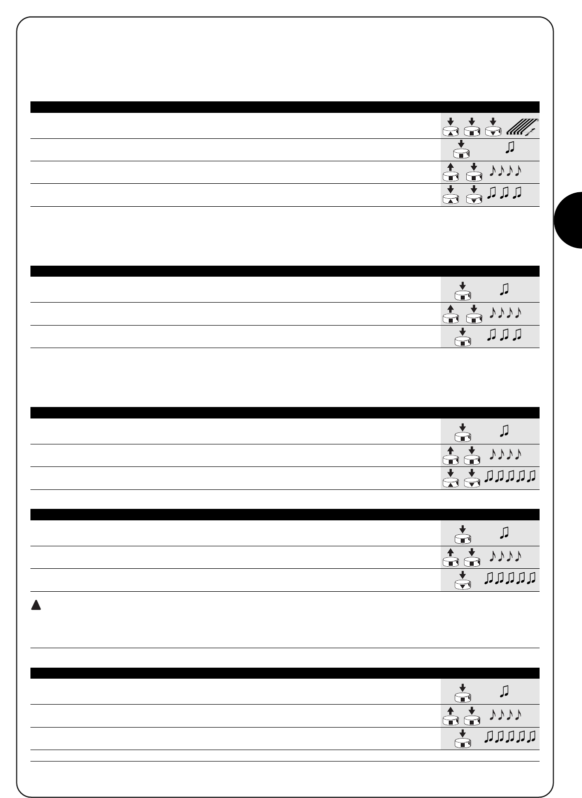
D
23
1. Die Markise mit den Tasten ▲oder ■und ▼einer Fernbedienung dorthin verschieben,
wo die Position “I” sein soll.
2. Die Taste ■gedrückt halten, bis man einen Biepton hört (nach ca. 5 Sekunden).
5s
3. Loslassen und noch mal 5 Sekunden lang auf die Taste ■drücken, bis man 4 Bieptöne
kurz aufeinander hört. 5s
4. Gleichzeitig auf die Tasten ▲und ▼ drücken, bis die Speicherung des Maßes durch 3
Bieptöne bestätigt wird.
Tabelle “A4” Programmierung der Zwischenposition “I” (abb. 10) Beispiel
4.3) Programmierung von Zusatzfunktionen
Zusatzfunktionen können erst programmiert werden, nachdem die Programmierung der Positionen “0” und “1” beendet ist.
4.3.1) Speicherung der Zwischenposition “I”
Zur Programmierung der Zwischenposition muss folgendes Verfahren durchgeführt werden:
1. Die Taste ■eines bereits gespeicherten Senders gedrückt halten, bis man einen Biepton
hört (nach ca. 5 Sekunden) 5s
2. Loslassen und noch mal 5 Sekunden lang auf die Taste ■drücken, bis man 4 Bieptöne
kurz aufeinander hört. 5s
3. Auf Taste ■drücken, bis 3 Bieptöne die Aktivierung der RDC-Funktion bestätigen werden.
Tabelle “A5” Programmierung der Drehmomentreduzierung (RDC) (abb. 11) Beispiel
4.3.2) Programmierung der Drehmomentreduzierung in Schließung (RDC)
Die Drehmomentreduzierung ist eine programmierbare Funktion, die das Zugmoment kurz vor dem vollständigen Schließen der Markise um
ca. 50% verringert, so dass ein zu starker Zug auf den Markisenstoff vermieden wird.
1. Die Taste ■eines bereits gespeicherten Senders gedrückt halten, bis man einen Biepton
hört (nach ca. 5 Sekunden). 5s
2. Loslassen und noch mal 5 Sekunden lang auf die Taste ■drücken, bis man 4 Bieptöne
kurz aufeinander hört. 5s
3. Gleichzeitig auf die Tasten ▼ ▲ drücken, bis das Löschen der Zwischenposition durch 5
Bieptöne bestätigt wird.
Tabelle “A6” Löschen der Zwischenposition “I” (abb. 10) Beispiel
4.3.3) Löschen der Positionen oder der RDC-Funktion
Um die vorher gespeicherten Positionen ändern zu können, müssen sie zuerst gelöscht werden; erst dann können die neuen Positionen pro-
grammiert werden.
1. Die Taste ■eines bereits gespeicherten Senders gedrückt halten, bis man einen Biepton
hört (nach ca. 5 Sekunden) 5s
2. Loslassen und noch mal 5 Sekunden lang auf die Taste ■drücken, bis man 4 Bieptöne
kurz aufeinander hört. 5s
3. Auf Taste ▼ drücken, bis das Löschen der Positionen “0“ und “1“ durch 5 Bieptöne
bestätigt wird.
ACHTUNG: Nach dem Löschen der Positionen “0” und “1” wird sich die Markise nur bewegen, solange der Steuer-
befehl gegeben wird, und es muss eine neue Position gespeichert werden.
Anmerkung: die eventuell programmierte Zwischenposition “I” und die RDC-Funktion werden mit diesem Vorgang nicht gelöscht. Wenn man
alles löschen will (auch die Sendercodes), ist auf Tabelle “A9” Bezug zu nehmen.
Tabelle “A7” Löschen der Positionen “0” und “1” (abb. 12) Beispiel
1. Die Taste ■eines bereits gespeicherten Senders gedrückt halten, bis man einen Biepton
hört (nach ca. 5 Sekunden) 5s
2. Loslassen und noch mal ■Sekunden lang auf die Taste 5 drücken, bis man 4 Bieptöne
kurz aufeinander hört. 5s
3. Auf Taste ■ drücken, bis die Deaktivierung der RDC-Funktion durch 5 Bieptöne bestätigt wird.
Anmerkung: Nun wird das Schließen der Markise mit Vollkraft beendet.
Tabelle “A8” Löschen der Funktion Drehmomentreduzierung (RDC) (abb. 11) Beispiel
!
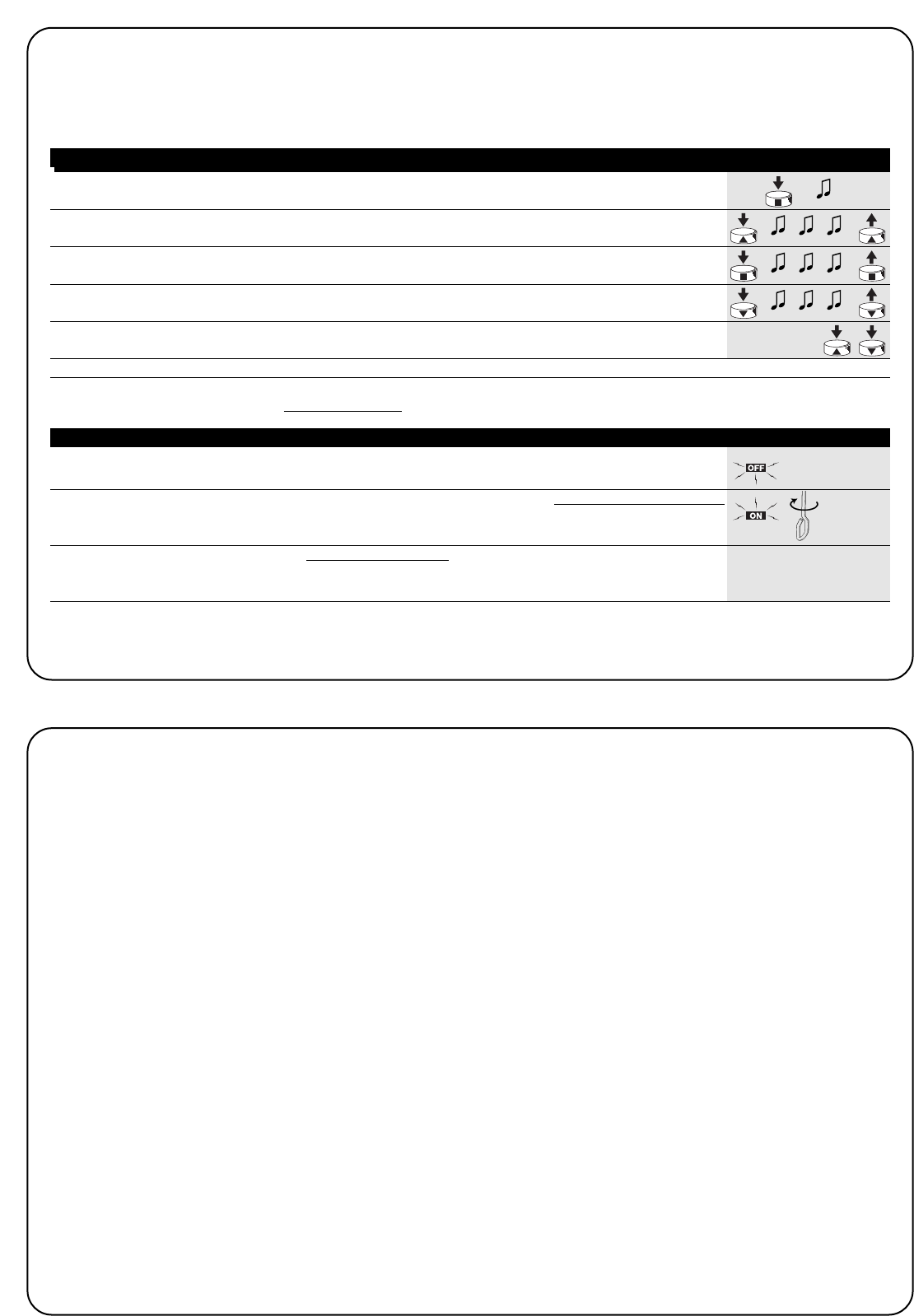
24
1. Die Taste ■des Senders gedrückt halten, bis man einen Biepton hört (nach ca. 5 Sekunden).
5s
2. Die Taste ▲des Senders gedrückt halten, bis man 3 Biept öne hört; die Taste ▲genau
während des dritten Bieptons loslassen. 5s
3. Die Taste ■des Senders gedrückt halten, bis man 3 Biept öne hört; die Taste ■genau
während des dritten Bieptons loslassen.
4. Die Taste ▼des Senders gedrückt halten, bis man 3 Biept öne hört; die Taste ▼genau
während des dritten Bieptons loslassen.
5. Falls man alle Daten löschen will, innerhalb von 2 Sekunden beide Tasten ▲und ▼gleichzeitig
drücken, dann loslassen.
innerhalb von 2s
Nach ein paar Sekunden werden 5 Bieptöne melden, dass alle Codes aus dem Speicher gelöscht worden sind.
Tabelle “A9” Löschen des Speichers mit einem bereits gespeicherten Sender (Abb. 13) Beispiel
Sollte es nötig sein, alle Daten im Speicher der NEOMAT H Motoren
zu löschen, kann das folgende Verfahren durchgeführt werden.
Das Löschen des Speichers ist möglich:
•mit einem bereits gespeicherten Sender (Tabelle “A9”)
•mit einem nicht gespeicherten Sender (Tabelle “A10”).
Gelöscht werden können:
•nur die Codes der Sender, wobei man das Verfahren an Punkt Nr.
4 beendet
•alle Daten (Sendercodes, Positionen, RDC-Funktion, usw.), indem
das ganze Verfahren durchgeführt wird.
➨
Zum Löschen des Speichers mit einer nicht gespeicherten Fernbedienung muss folgendes Verfahren durchgeführt werden:
Falls es die Anwendung erfordert, kann die Markise mit dem Wind- und Sonnewächter VOLO S RADIO automatisiert werden. Der korrekt
im Motor gespeicherte Wächter wird die Markise bei Sonne herunterlassen und im Falle von Wind aufrollen. Für vereinzelte Erläuterungen
über die Leistungen und die Programmierung der Stufen des Sensors wird auf die Anweisungen des Produkts VOLO S RADIO verwiesen.
1. Die Stromversorgung mindestens 3 Sekunden ausschalten.
3s
2. Die Stromversorgung wieder einschalten und die Notbedienung innerhalb von 10 Sekunden X6
mindestens 6 Umdrehungen drehen.
innerhalb
von 10s
3. Nun kann der Speicher innerhalb von 1 Minute mit dem in Tabelle “A9” beschriebenen
Verfahren mit einer beliebigen, auch nicht in den Speicher eingegebenen Fernbedienung “Tabelle A9”
gelöscht werden.
Tabelle “A10” Löschen des Speichers mit einem nicht gespeicherten Sender (Abb. 14) Beispiel
Nach seiner Versorgung gibt der Motor die 2 Bieptöne
nicht ab.
Kontrollieren, ob der Motor mit der vorgesehenen Netzspannung
gespeist ist, falls ja, liegt wahrscheinlich ein schwerer Defekt vor und
der Motor muss ausgewechselt werden..
Nach einem Befehl per Funk hört man 6 Bieptöne, aber
keine Bewegung erfolgt.
Die Funksteuerung ist nicht synchronisiert, der Sender muss neu
gespeichert werden.
Nach einem Befehl hört man 10 Bieptöne, dann erfolgt die
Bewegung.
Die Selbstdiagnose der gespeicherten Parameter hat eine Störung
festgestellt (Positionen, Programmierungen, Bewegungsrichtung sind
unkorrekt). Programmierungen kontrollieren und ggf. wiederholen.
Nach einem Steuerbefehl bewegt sich der Motor nicht
•Der Wärmeschutz könnte ausgelöst sein, in diesem Fall genügt
es zu warten, bis sich der Motor abgekühlt hat.
•Falls ein Windwächter gespeichert ist, könnte die eingestellte
Schwelle überschritten worden sein.
•Andernfalls den Motor ausschalten und wieder einschalten; wenn
man keine 2 Bieptöne hört, liegt wahrscheinlich ein schwerer
Defekt vor und der Motor muss ausgewechselt werden.
Während der Aufwärtsbewegung, bevor die vorgesehene
Position (Pos. “0”, Pos. “I”) erreicht wird, hält der Motor
an und versucht dann 3 Mal, wieder zu starten.
Kann normal sein: wenn bei der Aufwärtsbewegung eine zu große
Kraftanstrengung bemerkt wird, wird der Motor ca. 1 Sekunde lang
abgeschaltet, dann wird versucht, die Bewegung zu beenden; prü-
fen, ob die Bewegung durch etwas behindert ist.
Während der Abwärtsbewegung, bevor die vorgesehene
Position (Pos. “1”, Pos. “I”) erreicht wird, hält der Motor
an.
Kann normal sein: wenn bei der Abwärtsbewegung eine zu große
Kraftanstrengung bemerkt wird, wird der Motor abgeschaltet; prü-
fen, ob die Bewegung durch etwas behindert ist.
Der Motor bewegt sich nur, solange der Steuerbefehl
gegeben wird.
Wenn die Positionen “0” und “1” nicht programmiert worden sind, so
erfolgt die durch den Motor verursachte Auf- und Abwärtsbewegung
nur, solange der Steuerbefehl gegeben wird. Die Positionen “0” und
“1” programmieren.
Die Positionen “0” und “1” sind programmiert, aber die
Abwärtsbewegung erfolgt nur, solange der Steuerbefehl
gegeben wird.
Wahrscheinlich hat man die Notbedienung verwendet oder der
Motor war länger als 24 Stunden abgeschaltet. Einen Steuerbefehl
für die Aufwärtsbewegung der Markise geben und warten, bis die
Position “0“ erreicht wird.
5) Was tun, wenn… kleiner Leitfaden, wenn etwas nicht funktioniert!

D
25
6) Technische Merkmale
Rohrmotoren Serie NEOMAT H
Versorgungsspannung und Frequenz : siehe Technische Daten auf dem Etikett eines jeden Modells
Stromaufnahme und Leistung : siehe Technische Daten auf dem Etikett eines jeden Modells
Drehmoment und Geschwindigkeit : siehe Technische Daten auf dem Etikett eines jeden Modells
Dauerbetriebszeit : max. 4 Minuten
Arbeitszyklus : max. 20%
Schutzart : IP 44
Betriebstemperatur : -10 ÷ 50 °C
Präzision (Auflösung) des elektronischen Endschalters : größer als 0,55° (hängt von der NEOMAT H Version ab)
Dauer des Positionsspeichers bei Stromausfall : Über 24 Stunden
(mit automatischer Wiederfluchtung bei der ersten Anstiegsbewegung)
Funkempfänger
Frequenz : 433.92 MHz
Codierung : 52 Bit Rolling Code FLOR
Reichweite der Sender ERGO und PLANO : Auf freiem Feld und unter optimalen Bedingungen ca. 100-200 m und
20-30 m in Gebäuden
Reichweite der Sender VOLO S RADIO : Auf freiem Feld und unter optimalen Bedingungen ca. 100-200 m
Nice S.p.a. behält sich das Recht vor, jederzeit Änderungen am Produkt anzubringen.

26
Advertencias:
Atención: para la seguridad de las personas es importante
respetar estas instrucciones. Guarde este manual para
poderlo consultar posteriormente. Este manual contiene ins-
trucciones importantes para la seguridad, las instalaciones
incorrectas pueden originar situaciones graves de peligro.
Los motores serie “NEOMAT H” han sido realizados para automatizar el
movimiento de toldos, todo otro empleo se debe considerar impropio y
está prohibido. Los motores han sido diseñados para uso residencial;
se ha previsto un tiempo de trabajo continuo máximo de 4 minutos con
un ciclo del 20%. Al elegir el tipo de motor de acuerdo con su aplica-
ción, se deberá considerar el par nominal y el tiempo de funcionamien-
to indicados en la placa de características. El diámetro mínimo del tubo
en que se puede instalar el motor es 52mm para NEOMAT MH y 70mm
para NEOMAT LH. La instalación tiene que ser efectuada por personal
técnico, respetando las normas de seguridad, especialmente en lo refe-
rente a las conexiones eléctricas. La altura de instalación es de 2,5 m
como mínimo desde el suelo, garantizando igualmente un acceso fácil;
la distancia en horizontal entre el toldo completamente abierto y cual-
quier objeto fijo debe ser de 0,4m como mínimo. En los aparatos para
uso en exteriores, el cable de alimentación debe instalarse adentro de
un tubo de protección. Procure que el motor tubular no sufra aplasta-
mientos, golpes, caídas ni que tenga contacto con líquidos de ningún
tipo; no perfore ni aplique tornillos a lo largo del motor tubular (fig. 1).
Diríjase a personal técnico competente para el mantenimiento y las repa-
raciones.
Los botones de mando deben estar colocados en una posición desde
donde se vea el elemento que accionan, pero lejos de las piezas en
movimiento y a una altura de 1,5 m como mínimo. Aleje a las personas
del toldo cuando éste esté en movimiento. No accione el toldo si en las
cercanías se están realizando trabajos, por ejemplo limpieza de vidrios;
en el caso de accionamiento automático, desconecte también la ali-
mentación eléctrica. No permita que los niños jueguen con los mandos
y mantenga los controles remotos lejos de su alcance.
Los motores tubulares NEOMAT MH Ø45mm y NEOMAT LH
Ø58mm (fig. 2) tienen una central electrónica con radiorreceptor
incorporado que trabaja a una frecuencia de 433.92 MHz con tec-
nología rolling code, para garantizar niveles elevados de seguridad.
Para cada motor es posible memorizar hasta 14 radiomandos de la
serie "ERGO" y "PLANO" (fig. 3) o radiosensores, por ejemplo
“VOLO S RADIO” (fig. 3).
La central incorporada en el motor dispone de un sistema de fin de
carrera electrónico de alta precisión, que puede detectar constante-
mente la posición del toldo. Con una operación de programación se
memorizan los límites del movimiento, es decir toldo cerrado y toldo
abierto (más las probables posiciones intermedias); después de
cada mando el movimiento se detendrá automáticamente al alcan-
zar esas posiciones. El fin de carrera electrónico puede compensar
posibles estiramientos del toldo (función “CAT”) garantizando el cie-
rre perfecto del cajón y evitando que el toldo quede flojo cuando
esté abierto. Los motores NEOMAT H se pueden programar para la
reducción de par (función “RDC”) que disminuye de un 50% aproxi-
madamente el par del motor poco antes de que el toldo esté com-
pletamente cerrado para no tirar excesivamente de la lona.
NEOMAT H también prevé la función “RDT” que afloja un poco la
tensión sobre la lona una vez concluida la maniobra de cierre, a fin
de que la lona no quede muy tensa por períodos de tiempo muy pro-
longados. Las funciones CAT, RDC y RDT han sido estudiadas para
simular el comportamiento atento y diligente de una persona que
mueve el toldo manualmente.
La programación de los límites de movimiento y de algunas funcio-
nes adicionales es ejecutada por los radiomandos, un “Tono de avi-
so” (Bip) le guiará por las diferentes etapas. Los motores se pueden
accionar sólo por medio de los radiomandos o, como alternativa, el
toldo se puede mover usando la "maniobra de emergencia". El
movimiento del toldo puede ser automatizado según las condiciones
climáticas mediante el uso de radiosensores opcionales de viento,
sol, lluvia, por ejemplo “VOLO S RADIO”.
1) Descripción del producto
NEOMAT H es un producto de Motus S.p.a. (TV) I. ERGO, PLANO, VOLO S RADIO son productos de Nice S.p.a.(TV) I. Motus S.p.a. es una sociedad del grupo Nice S.p.a.
1.1) Maniobra de emergencia
Los motores tubulares NEOMAT H disponen de maniobra de emer-
gencia.
La maniobra de emergencia es un mecanismo que permite mover
manualmente el toldo, por ejemplo cuando falta la energía eléctrica.
Se utiliza por medio de la varilla colocada en la cabeza del motor,
girándola hacia un lado o hacia el otro.
Cuando se utiliza la maniobra de emergencia, o bien cuando el
motor queda sin energía eléctrica por más de 24 horas, la central de
mando del motor pierde el valor de la posición actual del toldo.
En esta situación se ha previsto una etapa de realineación automá-
tica; es suficiente efectuar una maniobra de subida hasta que el tol-
do quede cerrado completamente. Si antes de la realineación se
acciona la bajada del toldo, éste seguirá moviéndose sólo mientras
se mantenga accionado el mando.
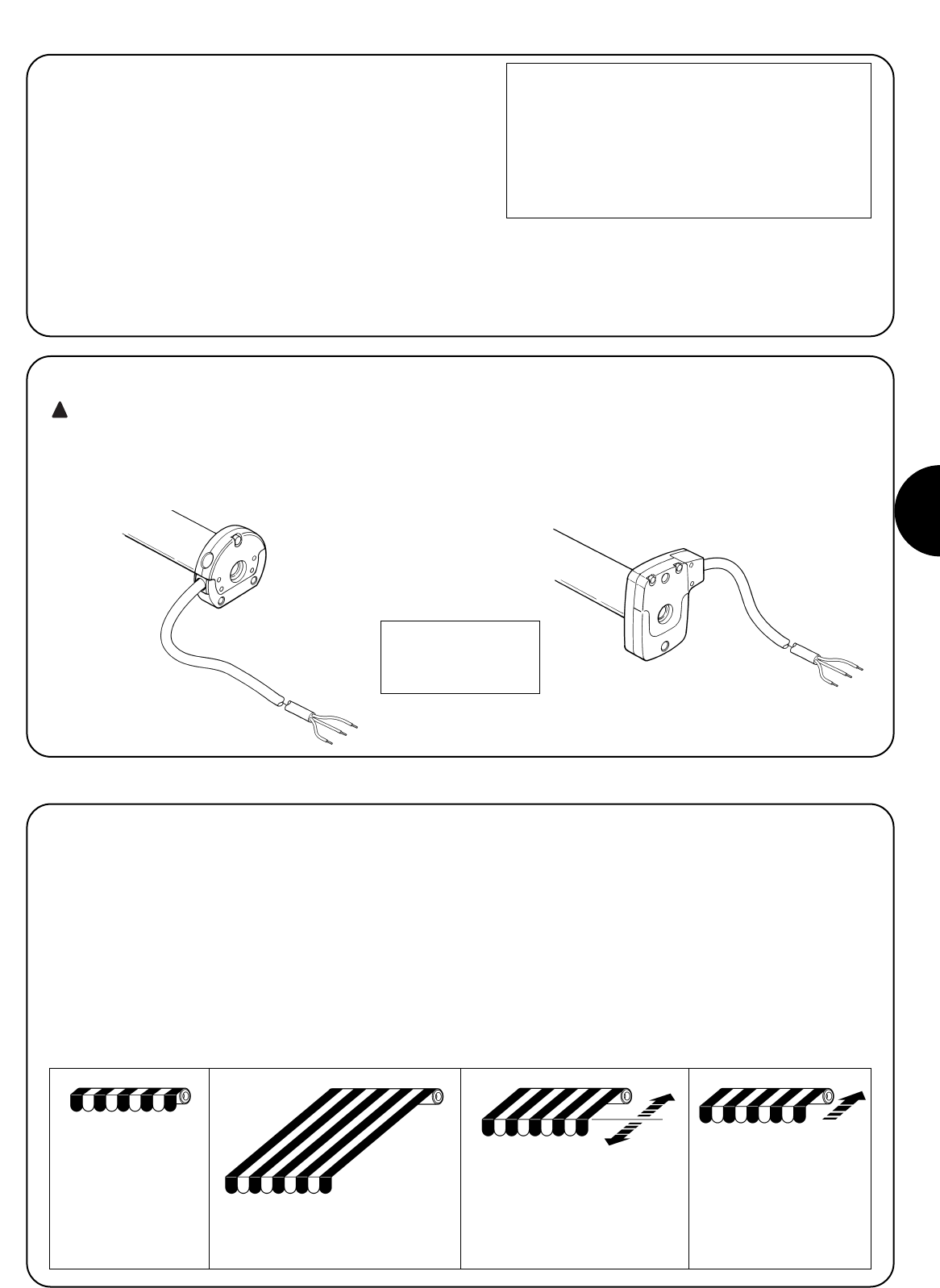
E
27
2) Instalación
Prepare el motor con la siguiente secuencia de operaciones (fig. 4):
1. Introduzca la corona (E) en el motor (A) hasta que entre en el
anillo (F) correspondiente.
2. Introduzca el adaptador de arrastre (D) en el árbol del motor.
3. En NEOMAT H fije el adaptador de arrastre con la arandela
seeger a presión.
Figura 4
A: Motor tubular NEOMAT H
B: Grapas, pasadores hendidos o tornillos para fijación
C: Soporte y distanciador
D: Adaptador de arrastre
E: Corona
F: Anillo
G: Manivela de emergencia
Los motores tubulares serie NEOMAT H disponen de un sistema de
fin de carrera electrónico; la central electrónica interrumpe el movi-
miento cuando el toldo llega a las posiciones de cierre y de apertu-
ra programadas. Dichas posiciones se memorizan con una progra-
mación oportuna que se debe hacer directamente con el motor ins-
talado y con el toldo montado.
Si aún no fueron memorizadas las posiciones “0” (toldo cerrado) y
“1” (toldo abierto) es posible accionar igualmente el motor, pero el
movimiento se ejecutará sólo en modo manual. También es posible
programar una posición intermedia (Pos. “I”) para abrir el toldo par-
cialmente. Si se memoriza una posición intermedia “I” es posible
mover el toldo hacia la posición programada oprimiendo simultáne-
amente los 2 botones ▼▲ del transmisor.
La posición “I” y la activación de la reducción de par (RDC) también
se pueden programar en un segundo momento.
3) Regulaciones
Introduzca el motor ensamblado de esta manera en el tubo en que
se enrolla el toldo hasta tocar el extremo de la corona (E).
Fije el tubo al adaptador de arrastre (D) con el tornillo M4x10 para
que el motor no se desplace ni se deslice axialmente (fig. 6).
Por último, bloquee la cabeza del motor al soporte respectivo (C),
con el distanciador Mediante las grapas, el pasador hendido o los
tornillos (B).
En la cabeza del motor existe la posibilidad de introducir una varilla
para mover el motor en condiciones de emergencia (maniobra de
emergencia).
2.1) Conexiones eléctricas
ATENCIÓN: en las conexiones del motor hay que pre-
ver un dispositivo omnipolar de desconexión de la red
eléctrica con distancia entre los contactos de 3 mm como
mínimo (interruptor o enchufe y tomacorriente, etc.).
El cable para las conexiones eléctricas del motor NEOMAT H dispo-
ne de 3 conductores de conexión:
•Fase, Neutro y Tierra.
Controle que la tensión de red corresponda a la placa de caracte-
rísticas de NEOMAT H.
!
Toldo completamente
cerrado (Pos. “0”)
Posición intermedia (“I”)
Posición de comienzo de la
reducción de par RDC en la
maniobra de cierre
Toldo abierto (Pos.”1”)
Marrón = Fase
Azul = Neutro
Amarillo/Verde = Tierra
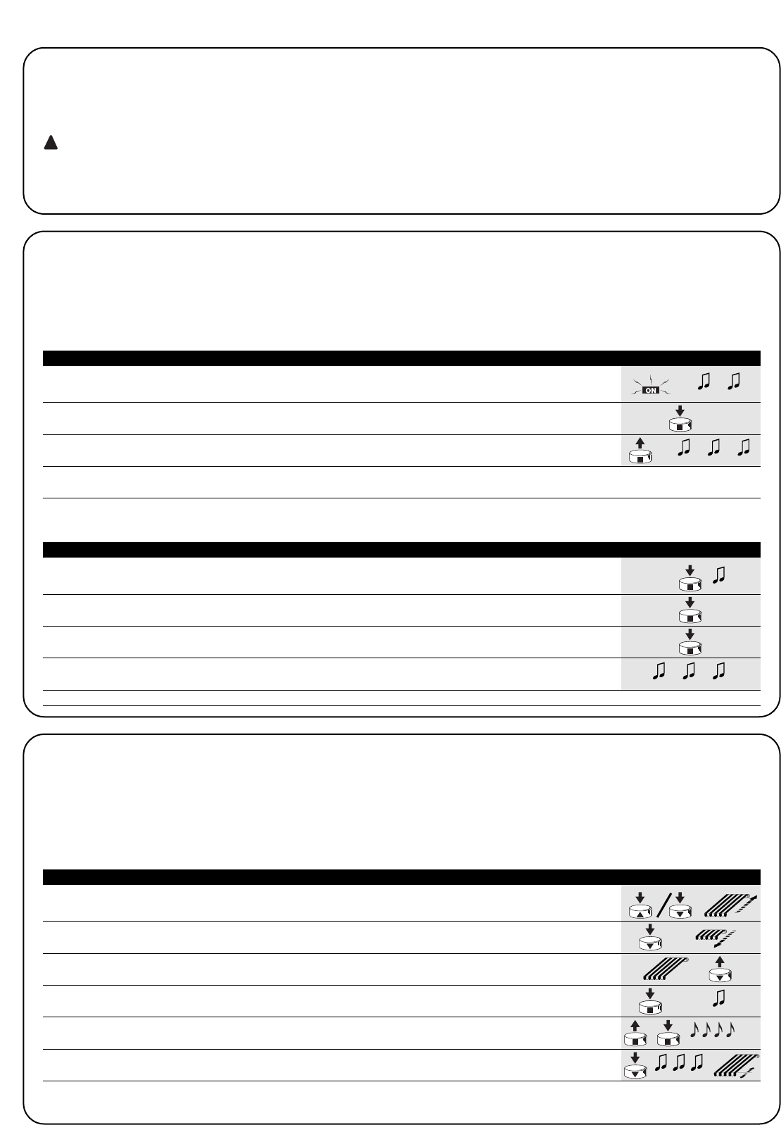
28
La programación se divide en 3 partes:
1. Memorización de los transmisores
2. Programación de las posiciones “0” y “1”
3. Programaciones opcionales
ATENCIÓN: Todas las secuencias de memorización de
los transmisores y de las programaciones de los paráme-
tros son por tiempo, es decir que tienen ser efectuadas
dentro de los límites de tiempo previstos.
•Con radiomandos que prevean varios “grupos”, antes de
proceder con la memorización hay que seleccionar el
grupo al que asociar el motor.
•La programación por radio se puede realizar en todos
los motores que se encuentran en el radio de alcance
del transmisor, por lo que es oportuno mantener ali-
mentado sólo aquel que debe ser programado.
4) Programación
1. Oprima y mantenga apretado el botón ▲o el botón ▼de un telemando memorizado hasta
que el toldo se cierre por completo y el motor se detenga automáticamente.
2. Oprima y mantenga apretado el botón ▼que hace bajar el toldo.
3. Suelte el botón ▼cuando el toldo haya llegado a la posición deseada (“1”).
Si fuera necesario, ajuste la posición con los botones ▼y ▲.
4. Mantenga apretado el botón ■del transmisor hasta oír un tono de aviso
(transcurridos alrededor de 5 segundos). 5s
5. Suelte y oprima de nuevo durante otros 5 segundos el botón ■hasta oír 4 tonos de
aviso rápidos. 5s
6. Oprima el botón ▼hasta que 3 tonos de aviso y un breve movimiento de subida y
bajada indiquen que la cota ha sido memorizada.
Tabla “A3” Programación de las Posiciones “0” y “1” (fig 9) Ejemplo
4.1) Memorización de los transmisores
Cada radiomando es reconocido por el receptor incorporado en la central de NEOMAT H por medio de un “código” diferente de cualquier otro.
Por eso es necesaria una etapa de “memorización” con la que se prepara a la central para que reconozca cada uno de los radiomandos.
Cuando en la memoria no hay ningún código, se puede proceder a memorizar el primer radiomando de la siguiente manera:
!
1. Ni bien se conecta la alimentación de la central, se oirán 2 tonos de aviso largos (biiip).
2. Antes de transcurridos 5 segundos, oprima y mantenga apretado el botón ■del transmisor
a que se debe memorizar (durante alrededor de 3 segundos). 3s
3.
Suelte el botón ■cuando oiga el primero de los 3 tonos de aviso que confirman la memorizació
n.
Nota: si la central ya contiene códigos, en el momento del encendido se oirán 2 tonos de aviso cortos (bip) y no se podrá proceder como
descrito, sino que habrá que usar el otro procedimiento de memorización (Tabla “A2”).
Tabla “A1” Memorización del primer transmisor (fig. 7) Ejemplo
1. Mantenga apretado el botón ■del transmisor nuevo hasta oír un tono de aviso
(después de alrededor de 5 segundos). Nuevo 5s
2. Oprima lentamente 3 veces el botón ■de un transmisor ya habilitado (viejo).
Viejo X3
3. Oprima de nuevo el botón ■del transmisor nuevo.
Nuevo
4. Al final, 3 tonos de aviso indicarán que el transmisor nuevo ha sido memorizado correctamente.
Nota: si la memoria está llena (14 códigos), 6 tonos de aviso indicarán que el transmisor no se puede memorizar.
Tabla “A2” Programación de las posiciones “0” y “1” (fig. 8) Ejemplo
Cuando han sido memorizados uno o varios transmisores, es posible habilitar otros de la siguiente manera:
4.2) Programación de las posiciones “0” y “1”
Para programar las posiciones hay que utilizar un telemando memorizado. Hasta que no se memoricen en la central las posiciones “0” y “1”,
los movimientos se efectúan en modo manual. Al principio, la dirección del motor no está definida, pero al completar el punto 1 de la Tabla
“A3” se asigna automáticamente la dirección del motor a los botones de los telemandos.
Para la programación de las posiciones 0 y 1 siga este procedimiento:
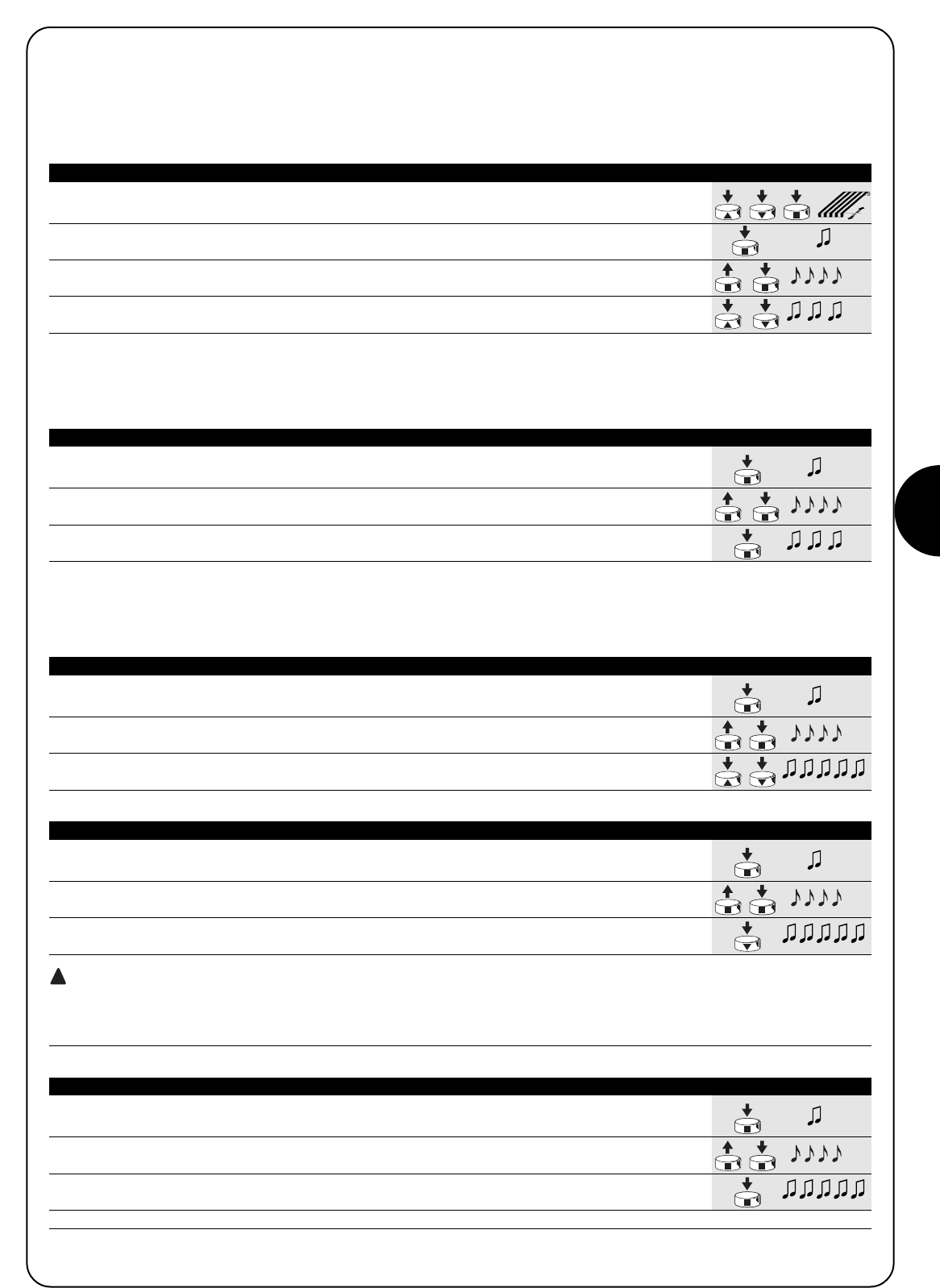
E
29
1. Utilizando los botones ▲o ▼y ■de un telemando coloque el toldo donde se quiere
memorizar la posición “I”.
2. Mantenga apretado el botón ■hasta oír un tono de aviso
(transcurridos alrededor de 5 segundos). 5s
3. Suelte y oprima de nuevo durante otros 5 segundos el botón ■hasta oír 4 tonos de
aviso rápidos. 5s
4. Oprima juntos los botones ▲ y ▼hasta que 3 tonos de aviso indiquen que la cota ha sido
memorizada.
Tabla “A4” Programación de la posición intermedia “I” (fig. 10) Ejemplo
4.3) Programaciones opcionales
Las programaciones opcionales están disponibles sólo tras haber concluido con las programaciones de las posiciones “0” y “1”.
4.3.1) Memorización de la posición intermedia “I”
Para memorizar la posición intermedia siga este procedimiento:
1. Mantenga apretado el botón ■de un transmisor memorizado hasta oír un tono de aviso
(transcurridos alrededor de 5 segundos) 5s
2. Suelte y oprima de nuevo durante otros 5 segundos el botón ■hasta oír 4 tonos de aviso
rápidos. 5s
3. Oprima el botón ■hasta que 3 tonos de aviso señalen que la función RDC ha sido activada.
Tabla “A5” Programación de la Reducción de Par (RDC) (fig. 11) Ejemplo
4.3.2) Programación de la Reducción de par durante el cierre (RDC)
La reducción de par es una función programable que reduce el par de tracción de alrededor del 50% antes del cierre completo del toldo,
para evitar una tensión excesiva de la lona.
1. Mantenga apretado el botón ■de un transmisor memorizado hasta oír un tono de aviso
(transcurridos alrededor de 5 segundos) 5s
2. Suelte y oprima de nuevo durante otros 5 segundos el botón ■hasta oír 4 tonos de aviso
rápidos. 5s
3. Oprima juntos los botones ▼ ▲ hasta que 5 tonos de aviso indiquen que la posición
intermedia ha sido cancelada.
Tabla “A6” Borrado de la posición intermedia “I” (fig. 10) Ejemplo
4.3.3) Borrado de las posiciones o de la función RDC
Para modificar las posiciones memorizadas con anterioridad, primero hay que borrarlas y después se puede volver a programar las nuevas
posiciones.
1. Mantenga apretado el botón ■de un transmisor memorizado hasta oír un tono de aviso
(transcurridos alrededor de 5 segundos) 5s
2. Suelte y oprima de nuevo durante otros 5 segundos el botón ■hasta oír 4 tonos de aviso
rápidos. 5s
3. Oprima el botón ■hasta que 5 tonos de aviso señalen que las posiciones “0” y “1” han
sido canceladas
ATENCIÓN: tras haber cancelado la posiciones “0” y “1” el toldo se moverá en modo manual y habrá que memorizar
otra posición nueva.
Nota: la posición intermedia “I” y la función RDC programadas no se cancelan. Si usted quiere cancelar todo (incluidos los códigos de los
transmisores) refiérase a la tabla “A9.”
Tabla “A7” Borrado de las posiciones “0” y “1” (fig. 12) Ejemplo
1. Mantenga apretado el botón ■de un transmisor memorizado hasta oír un tono de aviso
(transcurridos alrededor de 5 segundos). 5s
2. Suelte y oprima de nuevo durante otros 5 segundos el botón ■hasta oír 4 tonos de avis
rápidos. 5s
3. Oprima el botón ■hasta que 5 tonos de aviso señalen que la función RDC ha sido
desactivada.
Nota: ahora el toldo se terminará de cerrar con la fuerza plena
Tabla “A8” Borrado de la función reducción de par (RDC) (fig. 11) Ejemplo
!

30
1. Mantenga apretado el botón ■de un transmisor hasta que se oiga un tono
de aviso (después de alrededor de 5 segundos). 5s
2. Mantenga apretado el botón ▲del transmisor hasta que oiga 3 tonos de aviso;
suelte el botón ▲exactamente durante el tercer tono de aviso. 5s
3. Mantenga apretado el botón ■del transmisor hasta que oiga 3 tonos de aviso;
suelte el botón 5 exactamente durante el tercer tono de aviso.
4. Mantenga apretado el botón ▼del transmisor hasta que se oigan 3 tonos de aviso;
suelte el botón ▼exactamente durante el tercer tono de aviso.
5. Si Ud. desea borrar todos los datos, oprima juntos antes de 2 segundos los dos botones
▲y ▼y después suéltelos. antes de 2s
Pasados algunos segundos, 5 tonos de aviso indican que todos los códigos de la memoria han sido borrados.
Tabla “A9” Borrado de la memoria (fig. 13) Ejemplo
Si fuera necesario borrar todos los datos contenidos en la memoria
de la central en los motores NEOMAT H, se puede ejecutar este pro-
cedimiento.
La memoria se puede borrar:
•con un transmisor memorizado (tabla "A9")
•con un transmisor no memorizado (tabla "A10").
Se pueden borrar:
•sólo los códigos de los transmisores, terminando en el punto N° 4,
•todos los datos (códigos de los transmisores, posiciones, función
RDC, etc.) completando el procedimiento.
➨
Después de la alimentación, el motor no emite los 2 tonos
de aviso.
Controle que el motor esté alimentado con la tensión de red previs-
ta; si la alimentación es correcta, es probable que haya una avería
grave y entonces habrá que sustituir el motor.
Después de un mando por radio se oyen 6 tonos de aviso
y la maniobra no arranca.
El radiomando está desincronizado; hay que repetir la memorización
del transmisor.
Después de un mando se oyen 10 tonos de aviso y des-
pués la maniobra arranca.
El autodiagnóstico de los parámetros en la memoria ha detectado
alguna irregularidad (posiciones, programaciones, dirección del
movimiento son incorrectos); controle y, si fuera necesario, repita las
programaciones.
Después de un mando el motor no se mueve.
•Podría haberse desconectado la protección térmica en dicho
caso hay que esperar a que el motor se enfríe.
•Si hay memorizado un sensor de viento se podría haber supera-
do el umbral configurado.
•Si así no fuera, apague y encienda el motor, si no oye 2 tonos de
aviso es probable que se haya averiado gravemente y que tenga
que sustituirlo.
Durante la subida, antes de llegar a la posición prevista
(pos. “0”, pos. “I”), el motor se detiene y se oye que trata
de volver a arrancar 3 veces.
Puede ser normal: durante la subida, cuando se detecta un esfuer-
zo excesivo, el motor se apaga durante 1 segundo y luego trata de
concluir la maniobra; controle que no haya obstáculos que impidan
el movimiento.
Durante la bajada, antes de llegar a la posición prevista
(pos. “1”, pos “I”), el motor se detiene.
Puede ser normal: durante la bajada, cuando se detecta un esfuer-
zo excesivo, el motor se apaga; controle que no haya obstáculos
que impidan el movimiento.
El motor se mueve sólo en modo manual.
Si las posiciones “0” y “1” no fueron programadas el movimiento de
subida y bajada del motor se realiza sólo en modo manual. Progra-
me las posiciones “0” y “1”.
Las posiciones “0” y “1” están programadas, pero duran-
te la bajada el movimiento se produce en modo manual.
Es probable que se haya utilizado la maniobra de emergencia o que
el motor haya quedado apagado durante más de 24 horas. Accione
la subida del toldo y espere a que alcance la posición “0”.
5) Qué hacer si… pequeña guía en caso de problemas!
Para poder borrar la memoria con un telemando no memorizado, es necesario efectuar este procedimiento:
Si la aplicación lo requiere, es posible automatizar el toldo usando el sensor de viento y sol VOLO S RADIO. El sensor memorizado correc-
tamente en el motor baja el toldo cuando hay sol y lo levanta cuando hay viento. Para ver detalladamente las prestaciones y programación
de los niveles del sensor, consulte las instrucciones del producto VOLO S RADIO.
1. Corte la alimentación durante 3 segundos como mínimo.
3s
2. Active la alimentación y antes de transcurridos 10 segundos gire 6 vueltas como mínimo X6
la manivela de emergencia. antes
de 10s
3. Entonces, antes de transcurrido 1 minuto, es posible borrar la memoria efectuando el
procedimiento de la tabla “A9” con cualquier telemando, aunque no memorizado. “Tabla A9”
Tabla “A10” Borrado de la memoria con un transmisor no memorizado (fig. 14) Ejemplo

E
31
6) Características técnicas
Motores tubulares serie NEOMAT H
Tensión de alimentación y frecuencia : Véanse datos técnicos en la etiqueta de cada modelo
Corriente y potencia : Véanse datos técnicos en la etiqueta de cada modelo
Par y Velocidad : Véanse datos técnicos en la etiqueta de cada modelo
Tiempo de funcionamiento continuo : Máximo 4 minutos
Ciclo de funcionamiento : Máximo 20%
Clase de protección : IP 44
Temperatura de funcionamiento : -10 ÷ 50 °C
Precisión (resolución) del fin de carrera electrónico : Mayor que 0.55° (depende de la versión de NEOMAT H)
Duración de la memoria de la posición sin alimentación : Más de 24 horas (con realineación automática en la primera maniobra de subida)
Radiorreceptor
Frecuencia : 433.92 MHz
Codificación : 52 Bit rolling code FLOR
Alcance de los transmisores ERGO y PLANO : al aire libre y en condiciones ideales, estimada en 100-200 m y en 20-30 m
en el interior de edificios.
Alcance de los transmisores VOLO S RADIO : al aire libre y en condiciones ideales, estimada en 100-200 m
Nice S.p.a. se reserva el derecho de modificar los productos en cualquier momento cuando lo considere necesario.

32
Ostrzeżenia:
Uwaga: mając na uwadze bezpieczeństwo osób należy
przestrzegać niniejszych instrukcji
Przechowywać instrukcje w celu przyszłej konsultacji.
Niniejsza instrukcja zwiera ważne warunki bezpieczeństwa;
nieprawidłowe zainstalowania mogą stworzyć niebezpieczne
sytuacje.
Silniki z serii NEOMAT H służą do automatyzacji ruchu markiz i każde inne
ich zastosowanie jest nieprawidłowe i zabronione. Silniki przeznaczone są
do użytku w zespołach mieszkaniowych; czas pracy ciągłej przewidziany
jest na maksymalnie 4 minuty w cyklu 20%. Przy wyborze typu silnika, w
zależności od jego zastosowania, należy mieć na uwadze moment
nominalny i czas funkcjonowania wskazany na tabliczce znamionowej.
Minimalna średnica rury, gdzie może być zainstalowany silnik NEOMAT MH
ma wynosić 52 mm, dla silnika NEOMAT LH - 70 mm. Instalowanie ma być
wykonane przez techników według norm bezpieczeństwa; szczególnej
ostrożności należy zastosować przy wykonywaniu połączeń elektrycznych.
Minimalna wysokość instalowania od ziemi lub podłogi to 2,5 m z
zagwarantowaniem łatwego dostępu. Minimalna odległość w poziomie od
maksymalnie otwartej markizy do jakiegokolwiek obiektu stałego nie może
być mniejsza od 0,4 m. W urządzeniach montowanych na zewnątrz
przewód zasilający zainstalować wewnątrz kanalika zabezpieczającego.
Chronić silnik przed zgnieceniem, uderzeniem, spadnięciem lub kontaktem
z płynami jakiegokolwiek rodzaju; nie dziurawić i nie wkręcać śrub na całej
długości rury (rys. 1).
W celu czynności konserwacyjnych lub napraw zwrócić się do personelu
technicznego.
Przyciski sterujące mają znajdować się w miejscu dobrze widocznym i na
wysokości co najmniej 1,5m od ziemi.
Nie zawijać i odwijać markizy, gdy w pobliżu wykonywane są prace takie jak
na przykład mycie okien. Gdy markiza posiada sterowniki automatyczne
należy odłączyć zasilanie. Nie wolno dzieciom bawić się urządzeniami
sterującymi i ploty trzymać daleko od zasięgu dzieci.
Silniki rurowe NEOMAT MH Ø45mm i NEOMAT LH Ø58mm (rys.2)
posiadają centralę elektroniczną i wbudowany odbiornik radiowy, który
pracuje na częstotliwości 433.92 MHz z technologią rolling code,
gwarantując wysoki poziom bezpieczeństwa. Do każdego silnika
można wczytać do 14 pilotów z serii “ERGO” i “PLANO” (rys. 3) lub
czujniki radiowe, jak na przykład “VOLO S RADIO” (rys.3).
Wbudowana w silniku centrala posiada także system elektronicznych
wyłączników krańcowych dużej precyzji, który jest w stanie, w sposób
ciągły, odczytywać pozycję markizy.
W fazie programowania ustala się punkty graniczne markizy zamkniętej
i markizy otwartej (i ewentualne pozycje pośrednie); ruch markizy
zatrzyma się automatycznie po dojściu do tych dwóch pozycji.
Elektroniczny wyłącznik krańcowy jest w stanie skompensować
ewentualne wydłużenia płótna (funkcja “CAT”) gwarantując perfekcyjne
zamykanie skrzyni i zapobiegając rozluźnieniu się płótna, kiedy jest
otwarta. Silniki NEOMAT H mogą być zaprogramowane do redukcji
momentu (funkcja “RDC”) zmniejszając o około 50% moment silnika na
krótko przed całkowitym zamknięciem się markizy (nawinięciem)
unikając w ten sposób nadmiernego naciągnięcia płótna. NEOMAT H
przystosowany jest także do funkcji “RDT”, która zmniejsza
naciągnięcie płótna po zakończeniu ruchu zamykania, w taki sposób,
aby płótno nie pozostało nadmiernie naciągnięte przez dłuższy okres
czasu. Funkcje CAT. RDC i RDT zostały opracowane do symulacji
zachowania osoby, która ręcznie, ostrożnie i starannie odwija i nawija
markizę.
Programowanie granic ruchu i innych dodatkowych funkcji można
wykonać pilotem, sygnał akustyczny będzie kierował poszczególnymi
fazami. Silnikami można sterować tylko pilotem lub, alternatywie,
można poruszać markizę poprzez zastosowanie “ruchu awaryjnego”.
Ruch markizy może być zautomatyzowany poprzez zastawanie
opcjonalnych czujników wiatru, słońca i deszczu, kiedy warunki
klimatyczne tego wymagają jak na przyklad “VOLO S RADIO”.
1) Opis produktu
NEOMAT H jest produktem firmy Motus S.p.a. (TV) i. ERGO, PLANO, VOLO S RADIO są produktem firmy Nice S.p.a.(TV) Włochy. Motus S.p.a. jest spółką należącą do grupy Nice S.p.a Włochy.
1.1) Ruch awaryjny
Silniki rurowe NEOMAT H zaopatrzone są w ruch awaryjny.
Ruch awaryjny jest mechanizmem, który służy do ręcznego poruszania
markizy, na przykład, kiedy zabraknie prądu. Na głowicy silnika
zamontowana jest rączka, którą można obracać w jednym lub drugim
kierunku.
Kiedy zostanie zastosowany ruch awaryjny lub kiedy silnik nie otrzyma
prądu przez ponad 24 godziny to centrala sterująca silnikiem traci
aktualną wartość pozycji markizy.
W tej sytuacja przewidziana została faza zwolnienia automatycznego,
wystarczy wykonać ruch wzniesienia (zawijania) aż do całkowitego
zawinięcia markizy. Gdy przed fazą ustawienia w linii zarządzi się ruch
obniżania to ruch odbędzie się systemem ręcznym (czyli, że markiza
porusza się tylko kiedy przycisk jest naciśnięty).
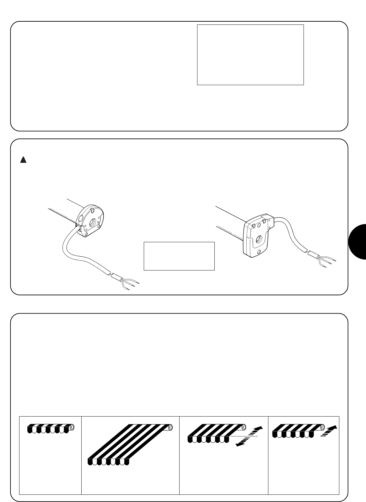
PL
33
2) Instalowanie
Przygotować silnik według następującej sekwencji (rys. 4):
1. Wsunąć tuleję (E) na silnik (A) do momentu założenia jej na
odpowiedni występ pierścienia (F).
2. Założyć adapter napędowy (D) na wał silnika.
3. Mocowanie adaptera na silniku NEOMAT H jest automatyczne na
zatrzask.
Rysunek 4
A: Silnik rurowy NEOMAT H
B: Haczyki, kołeczki lub wkręty mocujące
C: Wspornik i część dystansowa
D: Adapter napędowy
E: Tuleja
F: Pierścień
G: Ruch awaryjny
Silniki rurowe z serii NEOMAT H posiadają elektroniczny wyłącznik
krańcowy, który przerywa ruch, kiedy markiza osiągnie zaprogramowane
pozycje graniczne zamknięcia lub otwarcia.
Te dwie pozycje zapamiętane są w odpowiedniej fazie programowania,
którą należy wykonać z silnikiem i z markizą już całkowicie
zamontowaną.
Gdy pozycje “0” (markiza zamknięta) i “1” (markiza otwarta) nie zostały
jeszcze zapamiętane to sterowanie silnikiem jest również możliwe,
sposobem ręcznym. Można zaprogramować także pozycję pośrednią
(Pos. „I”) częściowego otwarcia markizy.
Gdy zapamiętana jest pozycja pośrednia “I” możliwe jest przestawienie
markizy do zaprogramowanej pozycji poprzez jednoczesne naciśnięcie
2 przycisków ▼▲ nadajnika.
Pozycja “I” i uaktywnienie redukcji momentu (RDC) mogą być
zaprogramowane w późniejszym czasie.
3) Regulacje
Wsunąć tak złożony silnik do rury nawijania markizy do momentu jej
nasunięcia na tuleję (E). Przykręcić rurę do adaptera (D) śrubą M4x10
tak, aby uniknąć możliwych przesunięć osiowych silnika (rys. 6).
Na koniec zablokować głowicę silnika we wsporniku (C), z ewentualną
częścią dystansową, za pomocą haczyków, kołeczka lub wkrętów
mocujących (B).
Na głowicy silnika przewidziana została możliwość przymocowania
rączki do awaryjnego napędu ręcznego silnika w wypadku braku prądu
(ruch awaryjny).
2.1) Połączenia elektryczne
UWAGA: przy podłączeniu silnika należy zastosować
wyłącznik wielobiegunowy do odłączenia od sieci elektrycznej,
gdzie odległość pomiędzy stykami ma wynosić co najmniej 3
mm (wyłącznik sekcyjny lub gniazdo i wtyczka, itp.)
Przewód do połączeń elektrycznych silnika NEOMAT H posiada 3 żyły:
•Faza, Neutralna i Uziemienie
Sprawdzić czy napięcie sieciowe jest takie jak to wskazane na
tabliczce znamionowej NEOMAT H.
!
Markiza całkowicie
zawinięta (Poz. “O”)
Pozycja pośrednia (“I”)
Pozycja początkowa redukcji
momentu RDC w ruchu
zamykania.
Markiza odwinięta (Poz. “1”)
Brązowy = Faza
Niebieski = Neutralny
Żółto/zielone = Uziemienie
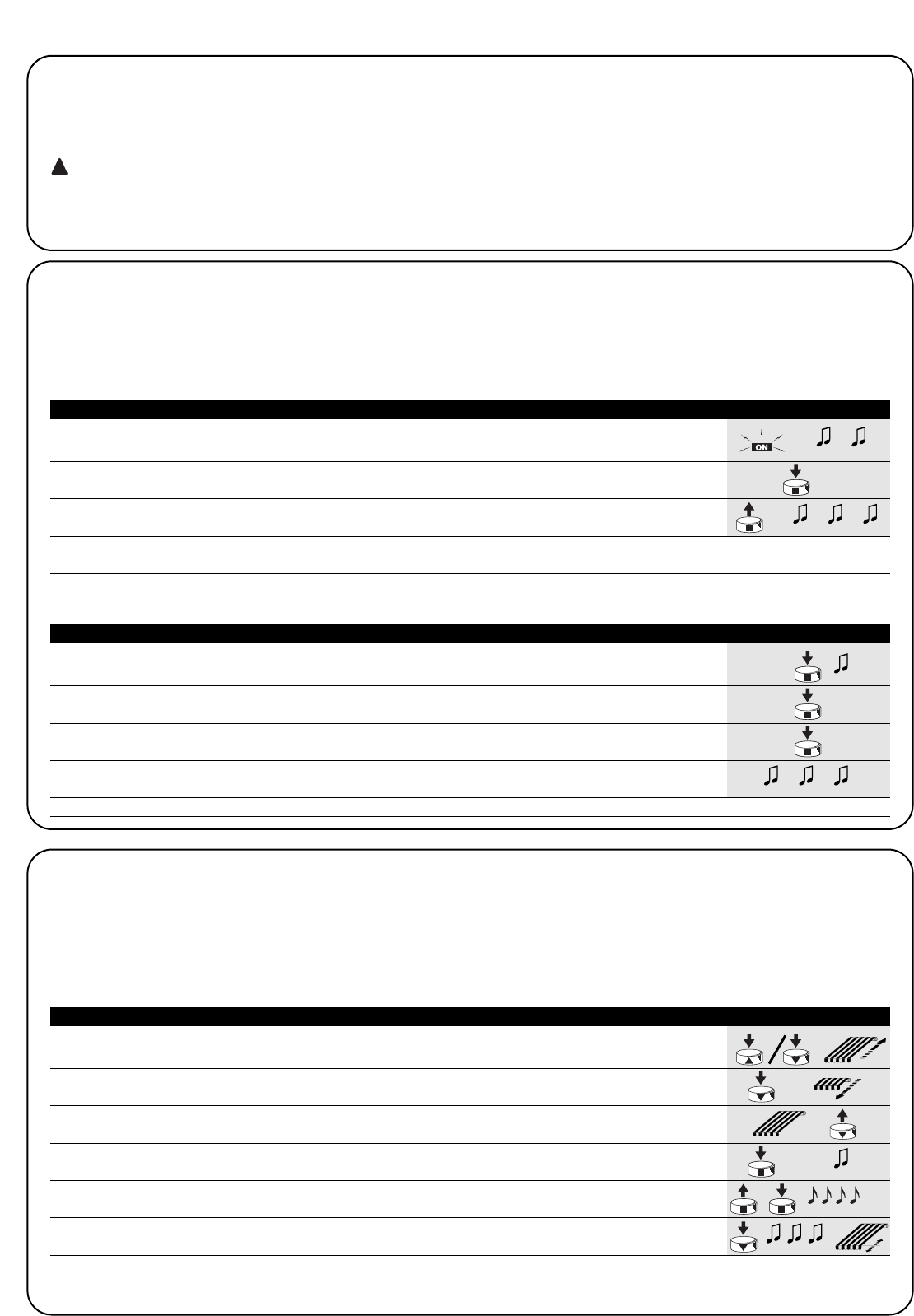
34
Programowanie podzielone jest na trzy fazy:
1. Wczytywanie nadajników
2. Programowanie pozycji “0” i “1”
3. Programowanie opcjonalne
UWAGA: Wszystkie sekwencje zapisywania nadajników i
programowanie parametrów są określone czasowo, to
znaczy, że należy je wykonać w ograniczonym czasie.
•Zapisywanie pilotów, gdzie przewidywane są “grupy” należy
wykonać po uprzednim wyborze grupy, do której dostosuje
się silnik.
•Programowanie drogą radiową można wykonać we
wszystkich silnikach, które znajdują się w zasięgu
nadajnika; zasilenie wówczas należy podłączyć tylko do
tego, który będzie programowany.
4) Programowanie
1. Przycisnąć i utrzymać pod naciskiem przycisk ▲lub przycisk ▼ pilota już zapisanego aż do
momentu, kiedy nawijanie zasłony zostanie zakończone i silnik zatrzyma się automatycznie.
2. Przycisnąć i utrzymać pod naciskiem przycisk ▼, który obniża zasłonę.
3. Zwolnić przycisk ▼kiedy zasłona osiągnie żądaną pozycję (“1”)
Gdy jest to konieczne wyregulować pozycję przyciskami ▲i ▼.
4. Przycisnąć i utrzymać pod naciskiem przycisk ■ nadajnika aż do usłyszenia sygnału
(po około 5 sekund). 5s
5. Zwolnić i ponownie przycisnąć na następne 5 sekund przycisk ■aż do usłyszenia
4 szybkich sygnałów.
6. Przycisnąć przycisk ▼ aż do momentu, kiedy 3 sygnały i krótki ruch wniesienia i obniżenia
zasygnalizuje, że wartość została zapisana.
Tabela “A3” Programowanie pozycji “0” i “1” (rys. 9) Przykład
4.1) Zapisywanie nadajników
Każdy pilot zostanie rozpoznawany przez wbudowany do centrali NEOMAT H odbiornik; rozpozna on indywidualny “kod” nadajnika.
Niezbędna jest, więc faza “zapisywania”, poprzez którą dostosowuje się centralę do rozpoznania każdego pojedynczego pilota.
Kiedy w pamięci nie ma żadnego kodu to pierwszy pilot zapisać według poniższej procedury:
!
1. Zaraz po zasileni centrali usłyszymy 2 długie sygnały (biiip)
2. W ciągu do 5 sekund przycisnąć i utrzymać pod naciskiem przycisk ■ wczytywanego
nadajnika (na około 3 sekundy).3s
3. Zwolnić przycisk ■ kiedy usłyszymy pierwszy z 3 sygnałów, które potwierdzą zapisanie.
Uwaga: Gdy w centrali już są zapisane kody to zaraz po jej włączeniu usłyszymy 2 krótkie sygnały (bip) i nie będzie możliwe wykonanie
czynności wyżej opisanych ale należy postąpić następująco (Tabela “A2”)
Tabela “A1” Zapisywanie pierwszego nadajnika (rys. 7) Przykład
1. Utrzymać pod naciskiem (przez około 5 s) przycisk ■ nowego nadajnika aż do usłyszenia sygnału
Nowy 5s
2. Powoli 3 krotnie przycisnąć przycisk ■nadajnika już wczytanego (starego).
Stary X3
3. Przycisnąć jeszcze raz przycisk ■ nowego nadajnika.
Nowy
4. Na zakończenie 3 sygnały potwierdzą prawidłowe zapisanie nowego nadajnika.
Uwaga: Gdy pamięć jest zapełniona (14 kodów), 6 sygnałów będzie oznaczało, że nadajnik nie będzie zapisany.
Tabela “A2” Zapisywanie innych nadajników (rys. 8) Przykład
Gdy jeden lub więcej nadajników zostały już zapisane to następne zapisujemy w poniższy sposób:
4.2) Programowanie pozycji “0” i “1”
Przy programowaniu pozycji należy zastosować pilot już zapisany. Do momentu, kiedy w centrali nie zostaną zapisane właściwe pozycje “0” i “1”.
ruch może być wykonany tylko ręcznie. Na początku kierunek obrotu silnika nie jest określony, ale po ustaleniu punktu 1 według tabeli “A3”
kierunek obrotu silnika zostanie automatycznie dostosowany do przycisków pilotów.
Programowanie pozycji 0 i 1 wykonać według poniższej procedury:
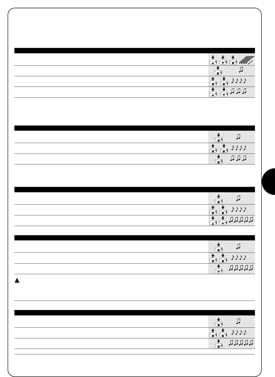
PL
35
1. Przyciskami ▲lub ▼i ■ pilota ustawić zasłonę na pozycji, którą zachowamy jako
pozycję pośrednią “I”.
2. Przycisnąć i utrzymać pod naciskiem przycisk ■ aż do usłyszenia sygnału (po około 5 sekundach).
5s
3. Zwolnić i ponownie przycisnąć na następne 5 sekund przycisk ■ aż do usłyszenia 4
szybkich sygnałów. 5s
4. Przycisnąć jednocześnie przyciski ▲ i ▼aż do momentu, kiedy 3 sygnały potwierdzą,
że wartość została zapisana.
Tabela “A4” Programowanie pośredniej pozycji “I” (rys. 10) Przykład
4.3) Programowanie opcjonalne
Opcjonalne programowanie jest możliwe tylko po zakończeniu programowania pozycji “0” i “1”.
4.3.1) Zapisywanie pozycji pośredniej “I”
Zapamiętywanie pośredniej pozycji wykonać według poniższej procedury:
1. Przycisnąć i utrzymać pod naciskiem przycisk ■nadajnika już wpisanego aż do usłyszenia
sygnału (po około 5 sekundach). 5s
2. Zwolnić i ponownie przycisnąć na następne 5 sekund przycisk ■aż do usłyszenia 4 szybkich
sygnałów. 5s
3. Przycisnąć przycisk ■ aż do momentu, kiedy 3 sygnały potwierdzą, że funkcja RDC została
uaktywniona.
Tabela “A5” Programowanie redukcji momentu (RDC) (rys. 11) Przykład
4.3.2) Programowanie redukcji momentu przy zamykaniu (nawijaniu) (RDC)
Redukcja momentu jest funkcją, którą można zaprogramować; redukuje ona moment naciągania o około 50% krótko przed całkowitym
zamknięciem markizy w skrzyni, czym unika się nadmiernego naciągnięcia płótna.
1. Przycisnąć i utrzymać pod naciskiem przycisk ■ nadajnika już wpisanego aż do usłyszenia
sygnału (po około 5 sekundach) 5s
2. Zwolnić i ponownie przycisnąć na następne 5 sekund przycisk ■ aż do usłyszenia 4 szybkich
sygnałów.5s
3. Przycisnąć jednocześnie przyciski ▲▼ aż do momentu, kiedy 5 sygnałów potwierdzą, że pozycja
pośrednia została skasowana.
Tabela “A6” Kasowanie pośredniej pozycji “I” (rys. 10) Przykład
4.3.3) Kasowanie pozycji lub funkcji RDC
Aby zmienić pozycje wcześniej ustalone należy je wykasować i ponownie zaprogramować.
1. Przycisnąć i utrzymać pod naciskiem przycisk ■ nadajnika już wpisanego aż do usłyszenia
sygnału (po około 5 sekundach) 5s
2. Zwolnić i ponownie przycisnąć na następne 5 sekund przycisk ■ aż do usłyszenia 4 szybkich
sygnałów.5s
3. Przycisnąć przycisk ▼ aż do momentu, kiedy 5 sygnałów potwierdzi, że pozycje “0” i “1”
zostały skasowane.
UWAGA: Po wykasowaniu pozycji “0” i “1” zasłona może być poruszana tylko ręcznie; konieczne jest więc zapisanie nowej
pozycji.
Uwaga: w powyższy sposób nie zostanie wykasowana pozycja pośrednia “I” i funkcja RDC, jeśli zostały zaprogramowane. Gdy chcemy
wykasować wszystko (wraz z kodami nadajników) należy zapoznać się z tabelą “A9.”
Tabela “A7” Kasowanie pozycji “0” i “1” (rys. 12) Przykład
1. Przycisnąć i utrzymać pod naciskiem przycisk ■ nadajnika już wpisanego aż do usłyszenia
sygnału (po około 5 sekundach) 5s
2. Zwolnić i ponownie przycisnąć na następne 5 sekund przycisk ■ aż do usłyszenia 4 szybkich
sygnałów. 5s
3. Przycisnąć przycisk ■ aż do momentu, kiedy 5 sygnałów potwierdzi, że funkcja RDC została
wyłączona.
Uwaga: Zasłona będzie nawijana z maksymalną siłą.
Tabela “A8” Kasowanie funkcji redukcji momentu (RDC) (rys. 11) Przykład
!
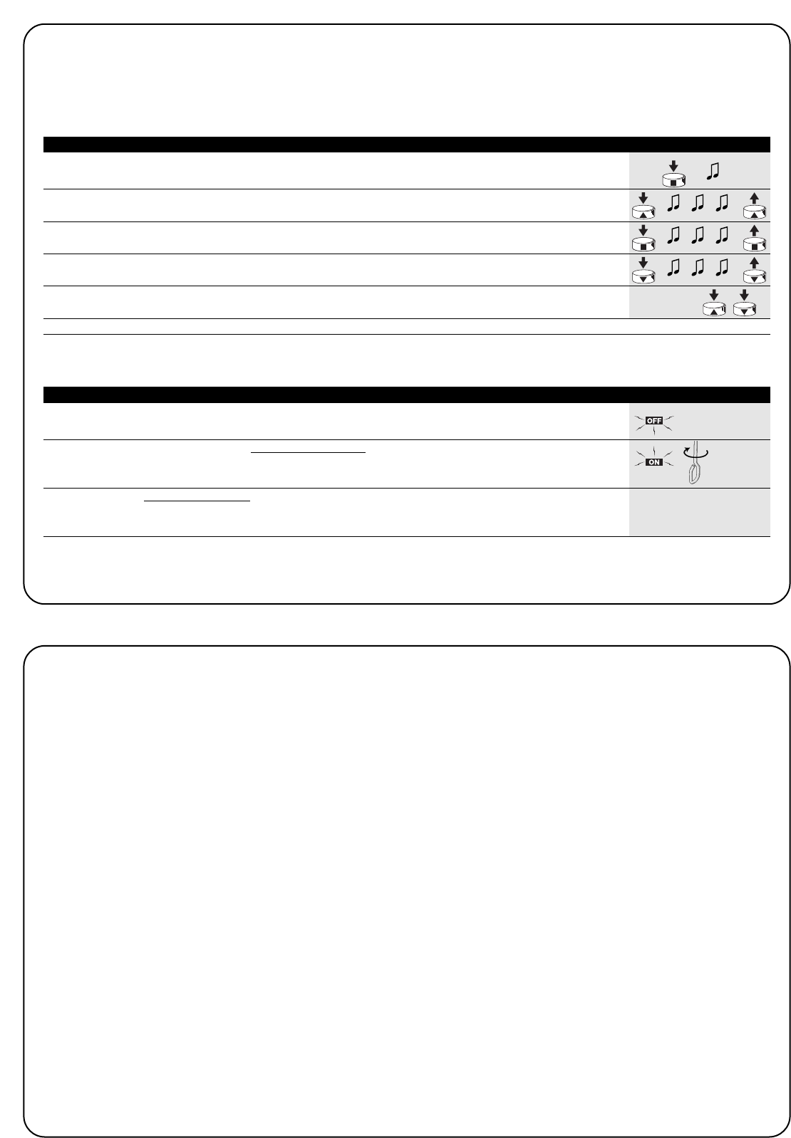
36
1. Utrzymać pod naciskiem przycisk ■już zachowanego nadajnika aż do
usłyszenia bip (po około 5 sekundach) 5s
2. Przycisnąć i utrzymać pod naciskiem ▲ przycisk nadajnika aż do usłyszenia 3 sygnałów;
zwolnić przycisk ▲dokładnie w momencie trwania trzeciego sygnału. 5s
3. Przycisnąć i utrzymać pod naciskiem ■ przycisk nadajnika aż do usłyszenia 3 bip;
zwolnić przycisk ■ dokładnie w momencie trwania trzeciego sygnału.
4. Przycisnąć i utrzymać pod naciskiem przycisk ▼nadajnika aż do usłyszenia 3 sygnałów;
zwolnić przycisk ▼dokładnie w momencie trwania trzeciego sygnału.
5. Gdy chcemy skasować wszystkie dane to w ciągu 2 sekund przycisnąć jednocześnie ▲e ▼,w ciągu
później zwolnić je. do 2 s
Po kilku sekundach 5 sygnałów potwierdzi, że wszystkie kody w pamięci zostały wykasowane.
Tabela “A9” Kasowanie pamięci z nadajnikiem już zapisanym (rys.13) Przykład
Gdy zajdzie konieczność wykasowania całej zawartości pamięci w
silnikach NEOMAT H, można postąpić według poniższej procedury:
Kasowanie pamięci yest możliwe:
•już zapisanym (tabela “A9”)
•nie zapisanym nadajnikiem (tabela “A10”)
Można wykasować:
•tylko kody nadajników kończąc na punkcie N 4
•wszystkie dane (kody nadajników, pozycje, funkcje RDC, itp.)
wykonując całą procedurę.
➨
Po podłączeniu zasilania silnik nie wydaje 2 sygnałów Bip.
Sprawdzić, czy silnik podłączony został do sieci z odpowiednim
napięciem, gdy zasilenie jest właściwe to jest możliwe, że silnik jest
wadliwy i powinien być wymieniony.
Po wydaniu polecenia drogą radiową słyszymy 6 sygnałów,
ale ruch nie odbywa się.
Pilot nie został zsynchronizowany, należy powtórzyć zapisywanie
nadajnika.
Po wydaniu polecenia słyszymy 10 sygnałów i później ruch
startuje.
Autodiagnoza parametrów w pamięci odczytała jakąś anomalię
(pozycje, programowania, kierunek ruchu są błędne). Sprawdzić i
ewentualnie powtórzyć programowanie
Po wydaniu komendy silnik nie rusza się
•Być może zainterweniowało zabezpieczenie termiczne, w tym
wypadku wystarczy odczekać do momentu ochłodzenia się silnika.
•Gdy zapisany jest czujnik wiatru to może został przekroczony próg
czułości.
•Można też wyłączyć i włączyć silnik, gdy nie usłyszymy 2 sygnałów
to możliwe, że jest to poważny powód i silnik powinien być
wymieniony.
W trakcie wzniesienia i przed osiągnięciem ustawionej
pozycji (poz. “0”, poz. “I”), silnik zatrzymuje się i słyszymy, że
3 krotnie wykonuje próbę startu.
To objaw normalny przy przeciążeniu: gdy w trakcie wzniesienia
odczytane zostanie przeciążenie to silnik włączony zostanie na 1
sekundę, po której ponownie wykonuje próbę startu. Sprawdzić i
wyeliminować ewentualne przeszkody.
Przy obniżaniu przed osiągnięciem zaprogramowanej pozycji
(poz. “1”, poz. “I”), silnik zatrzymuje się.
To objaw normalny: gdy w trakcie obniżania odczytane zostanie
przeciążenie to silnik zostanie wyłączony; sprawdzić i wyeliminować
ewentualne przeszkody.
Silnik porusza się tylko w ruchu ręcznym.
Gdy pozycje “0” i “1” nie zostały zaprogramowane to ruch silnika
wzniesienia i obniżenia odbędzie się tylko ręcznie. Zaprogramować
pozycję “0” i “1”.
Pozycje “0” i “1” są zaprogramowane, ale obniżanie odbywa
się ręcznie.
Możliwe jest, że zastosowany został ruch awaryjny i silnik został
wyłączony na ponad 24 godziny.
Polecić wzniesienie markizy i odczekać do momentu osiągnięcia
pozycji “0”.
5) Co zrobić, kiedy... zyli mały poradnik w momencie, kiedy coś jest nie tak!
Aby skasować z pamięci pilotem nie zachowanym należy wykonać poniższą procedurę.
Gdy jest to konieczne można zautomatyzować markizę poprzez zastosowanie czujnika wiatru i słońca VOLO S RADIO. Prawidłowo zapisany
czujnik w silniku obniża markizę, gdy wyjdzie słońce i zawinie markizę, gdy jest wiatr. Regulację wydajności i programowanie poziomów wykonuje
się.Według instrukcji produktu VOLO S RADIO.
1. Wyłączyć zasilenie przez co najmniej 3 sekundy.
3s
2. Podłączyć zasilenie i w ciągu do 10 sekund wykonać rączką korbką), co najmniej 6 obroty. X6
w ciągu
do 10 s
3. W ciągu do 1 minuty można skasować dane w pamięci według procedury opisanej w tabeli
“A9” jakimkolwiek pilotem, nawet pilotem nie wpisanym do pamięci. “Tabela A9”
Tabela “A10” Kasowanie pamięci nie zapisanym pilotem (rys. 14) Przykład

PL
37
6) Dane techniczne
Silniki rurowe z serii NEOMAT H
Napięcie zasilania i częstotliwość : Patrz dane techniczne na etykietce każdego typu
Prąd i moc : Patrz dane techniczne na etykietce każdego typu
Moment i prędkość : Patrz dane techniczne na etykietce każdego typu
Czas ciągłej pracy : Maksymalnie 4 minuty
Cykl pracy : Maksymalnie 20%
Stopień zabezpieczenia : IP 44
Temperatura funkcjonowania : -10 ÷ 50 °C
Dokładność (rozdzielczość) elektronicznego wyłącznika krańcowego : Wyższa niż 0.55 (Zależy od typu NEOMAT H)
Czas trwania pozycji bez prądu : Ponad 24 godziny
(z automatycznym ustawianiem w linii przed ruchem wzniesienia)
Odbiornik radiowy
Częstotliwość : 433.92 MHz
Kodowanie : 52 Bit rolling code (kod dynamicznie zmienny) FLOR
Zasięg nadajników ERGO i PLANO : w wolnej przestrzeni i w optymalnych warunkach określony jest
na 100 - 200 m i 20 – 30 m wewnątrz budynków
Zasięg nadajników VOLO S RADIO : w wolnej przestrzeni i w optymalnych warunkach określony jest
na 100 - 200 m
Firma Nice S.p.a. rezerwuje sobie prawo do wprowadzenia zmiany w produktach w każdym momencie, gdy będzie uważała to za konieczne.
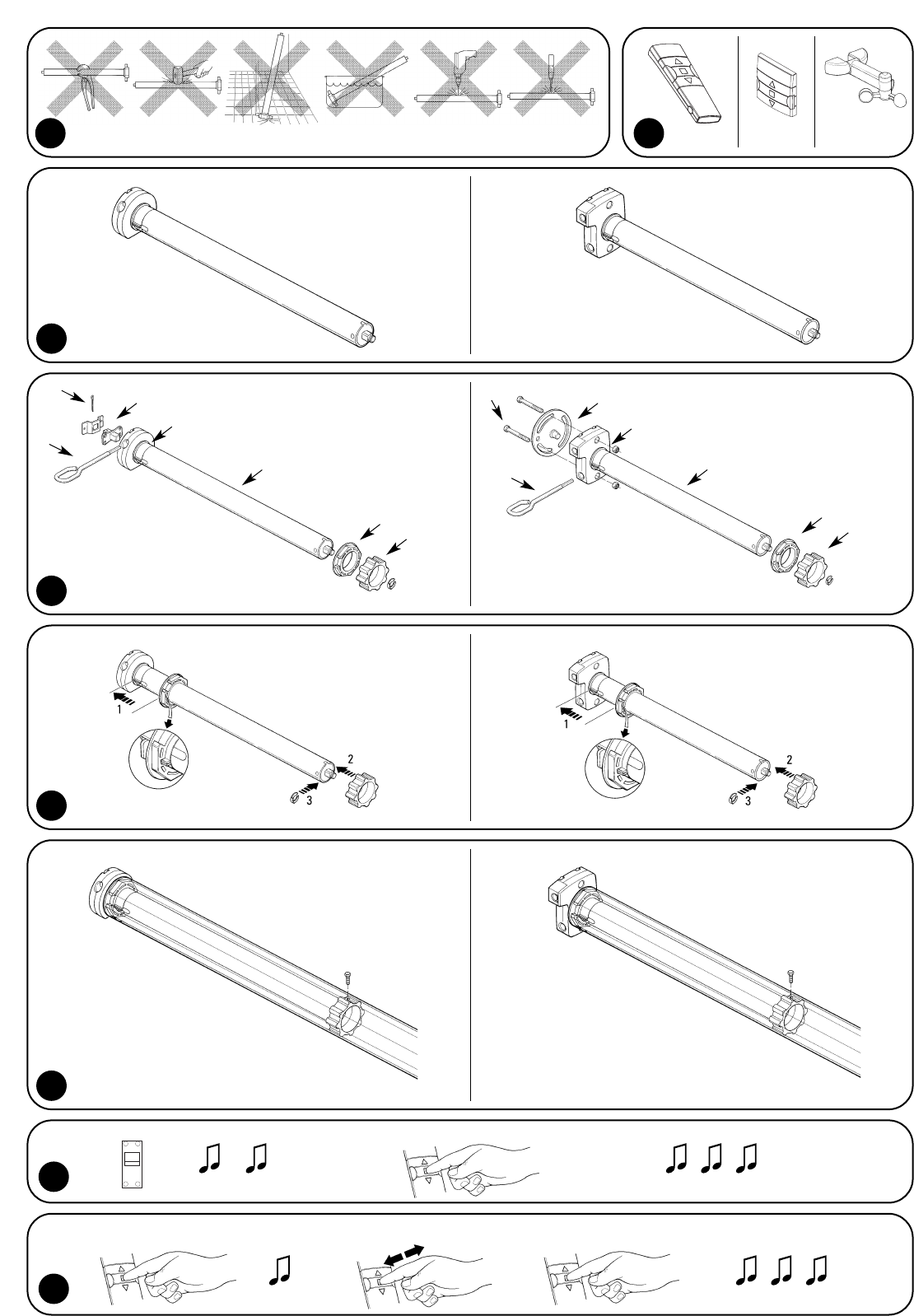
38
2
3
NEOMAT MH NEOMAT LH
4
5
6
B
A
B
1ERGO PLANO
VOLO S
RADIO
7
ON
8
~3 s
+5 s X3 X1
C
ED
F
A
C
ED
F
G
G
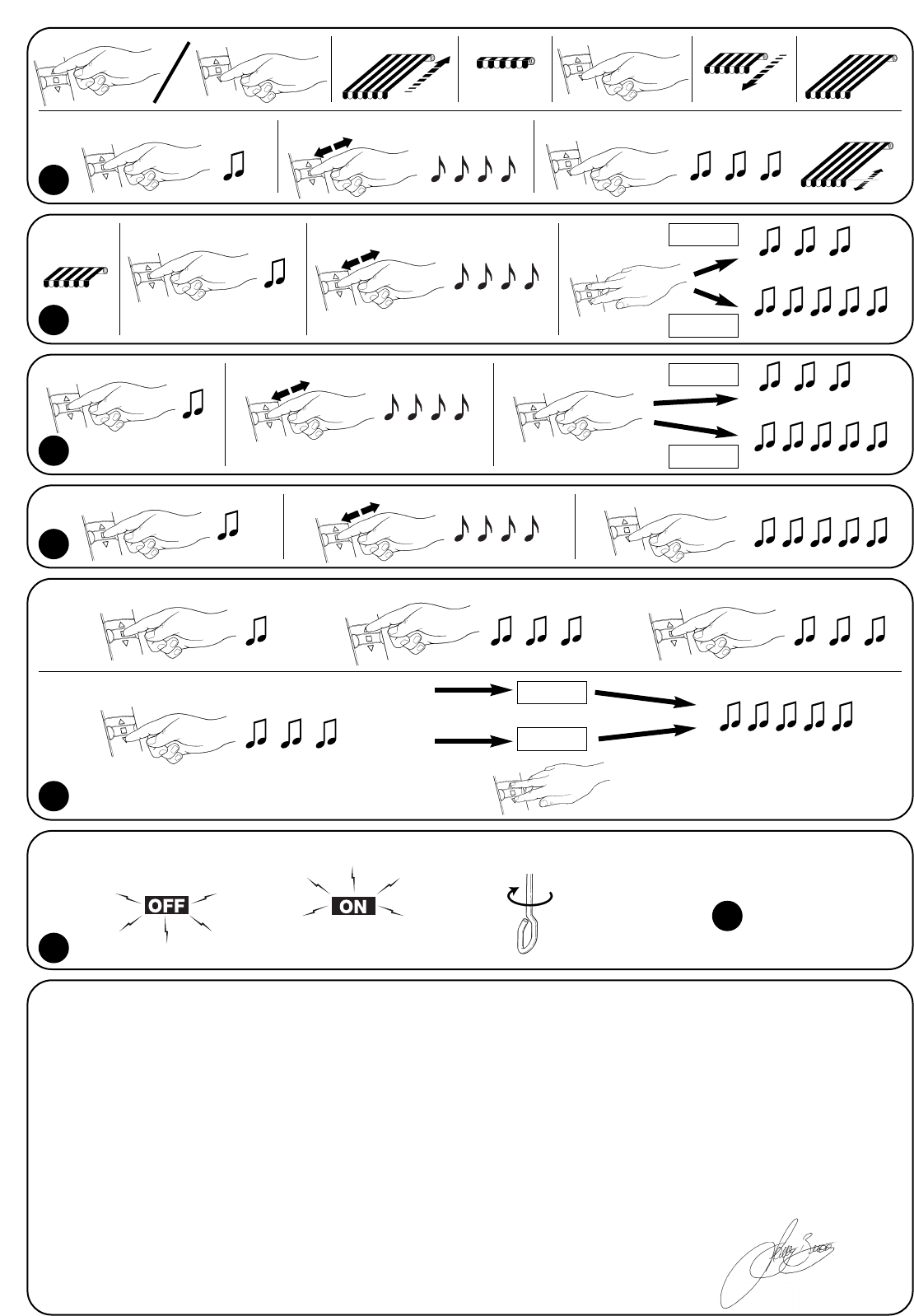
39
Dichiarazione di conformità N°: AXIS NEMO H Rev 1
declaration of conformity
NEOMAT MH e NEOMAT LH è prodotto da MOTUS S.p.a. (TV) I ed è identico al corrispettivo modello AXIS NEMO MEDIUM-H e AXIS NEMO LARGE-H.
Motus S.p.a. è una società del gruppo Nice S.p.a.
NEOMAT MH and NEOMAT LH is produced by Motus S.p.a. (TV) I and is identical of the corresponding model AXIS NEMO MEDIUM-H and AXIS NEMO LARGE-H.
Motus S.p.a. is a company of the Nice S.p.a. group.
MOTUS S.p.a. via Pezza Alta 13, 31046 Z.I. Rustignè - ODERZO - ITALY
dichiara che il prodotto: “AXIS NEMO MEDIUM-H e
AXIS NEMO LARGE-H
” / declares that the product: “AXIS NEMO MEDIUM-H and AXIS NEMO LARGE-H”
motoriduttore per tende da sole / gear motor for awnings
risulta conforme ai requisiti essenziali di sicurezza delle direttive: / complies with the essential safety requirements of directives:
73/23/CEE Direttiva Bassa Tensione (LVD) / Low Voltage Directive
89/336/CEE Direttiva compatibilità elettromagnetica (EMC) / Electromagnetic compatibility Directive
1999/5/CE Apparecchiature radio e terminali di telecomunicazione (R&TTE) / Radio equipment and telecomunications terminal
Risulta conforme a quanto previsto dalle altre norme e/o specifiche tecniche di prodotto:
Appears to be in conformity with the other standards and / or product technical:
LVD: EN 60335-1; EN 60335-2-97; IEC 60335-2-97
EMC: EN 55014; EN 61000-3-2; EN50082-1
R&TTE: ETS 300220-3; ETS 300683; EN 60950
Amministratore Delegato / General Manager
Data /date Lauro Buoro
20 Gennaio 2003
9
14
13
2 s
Only TX
3° bip
3° bip 3° bip+5 s
+5 s
+3 s within 10 s within 1 m
" "
-2 s X 1
All
+5 s
10
+5 s +5 s program
erase
11
+5 s +5 s program
erase
12
+5 s +5 s
13
X6

89.027/NMMT REV. 00
www.niceforyou.com
Nice S.p.a. Oderzo TV Italia
Via Pezza Alta, 13 Z.I. Rustignè
Tel. +39.0422.85.38.38
Fax +39.0422.85.35.85
info@niceforyou.com
Nice Padova Sarmeola I
Tel. +39.049.89.78.93.2
Fax +39.049.89.73.85.2
info.pd@niceforyou.com
Nice Roma I
Tel. +39.06.72.67.17.61
Fax +39.06.72.67.55.20
info.roma@niceforyou.com
Nice Belgium
Leuven (Heverlee) B
Tel. +32.(0)16.38.69.00
Fax +32.(0)16.38.69.01
info@nicebelgium.be
Nice España Madrid E
Tel. +34.9.16.16.33.00
Fax +34.9.16.16.30.10
kamarautom@nexo.es
Nice France Buchelay F
Tel. +33.(0)1.30.33.95.95
Fax +33.(0)1.30.33.95.96
info@nicefrance.fr
Nice France Sud Aubagne F
Tel. +33.(0)4.42.62.42.52
Fax +33.(0)4.42.62.42.50
info.marseille@nicefrance.fr
Nice Rhône-Alpes
Decines Charpieu F
Tel. +33.(0)4.78.26.56.53
Fax +33.(0)4.78.26.57.53
info.lyon@nicefrance.fr
Nice Polska Pruszków PL
Tel. +48.22.728.33.22
Fax +48.22.728.25.10
nice@nice.com.pl