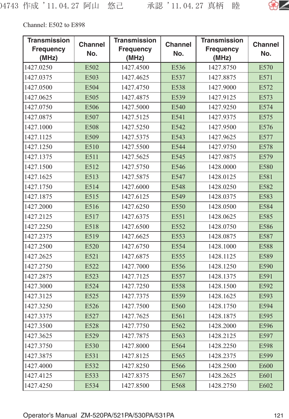
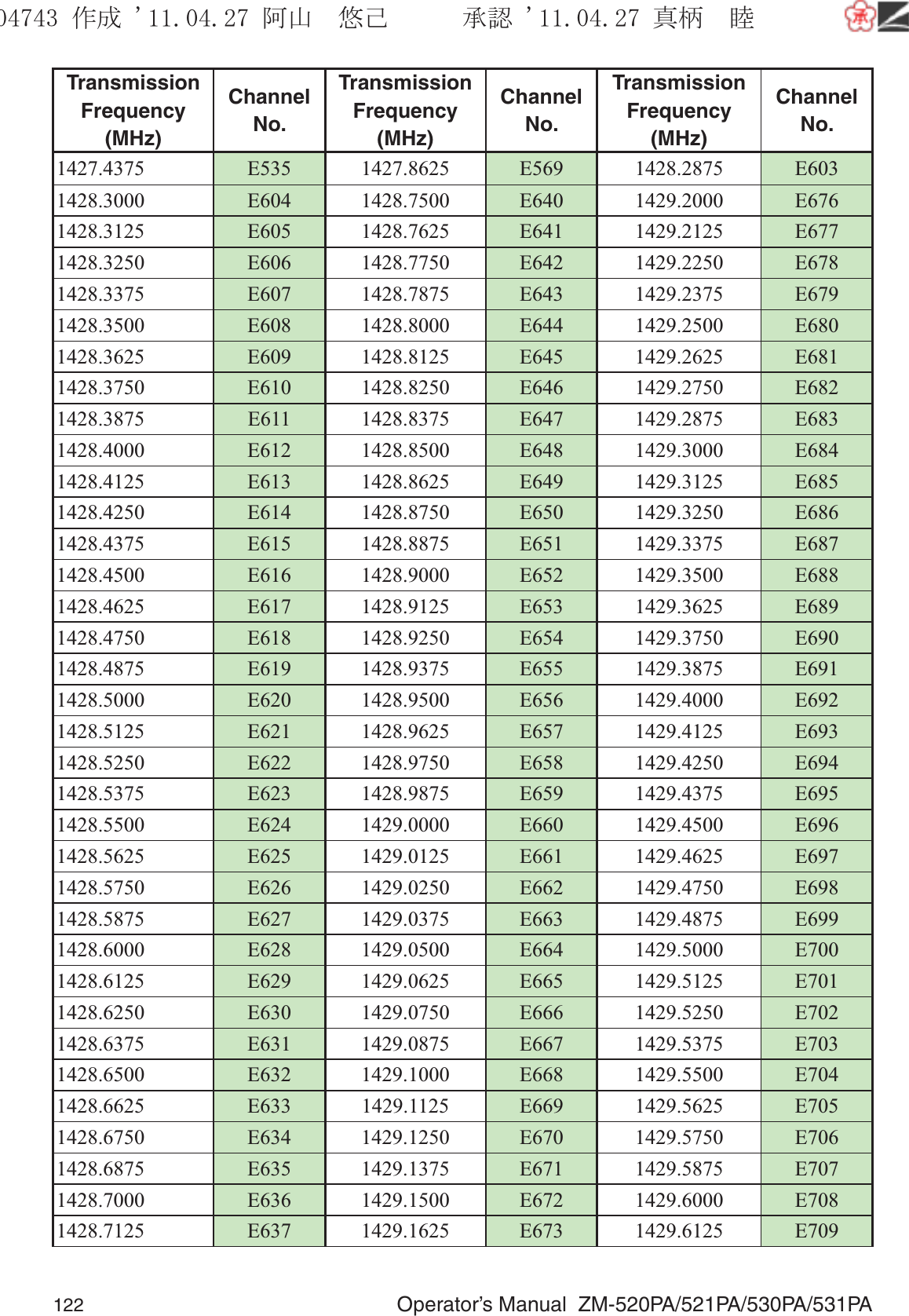
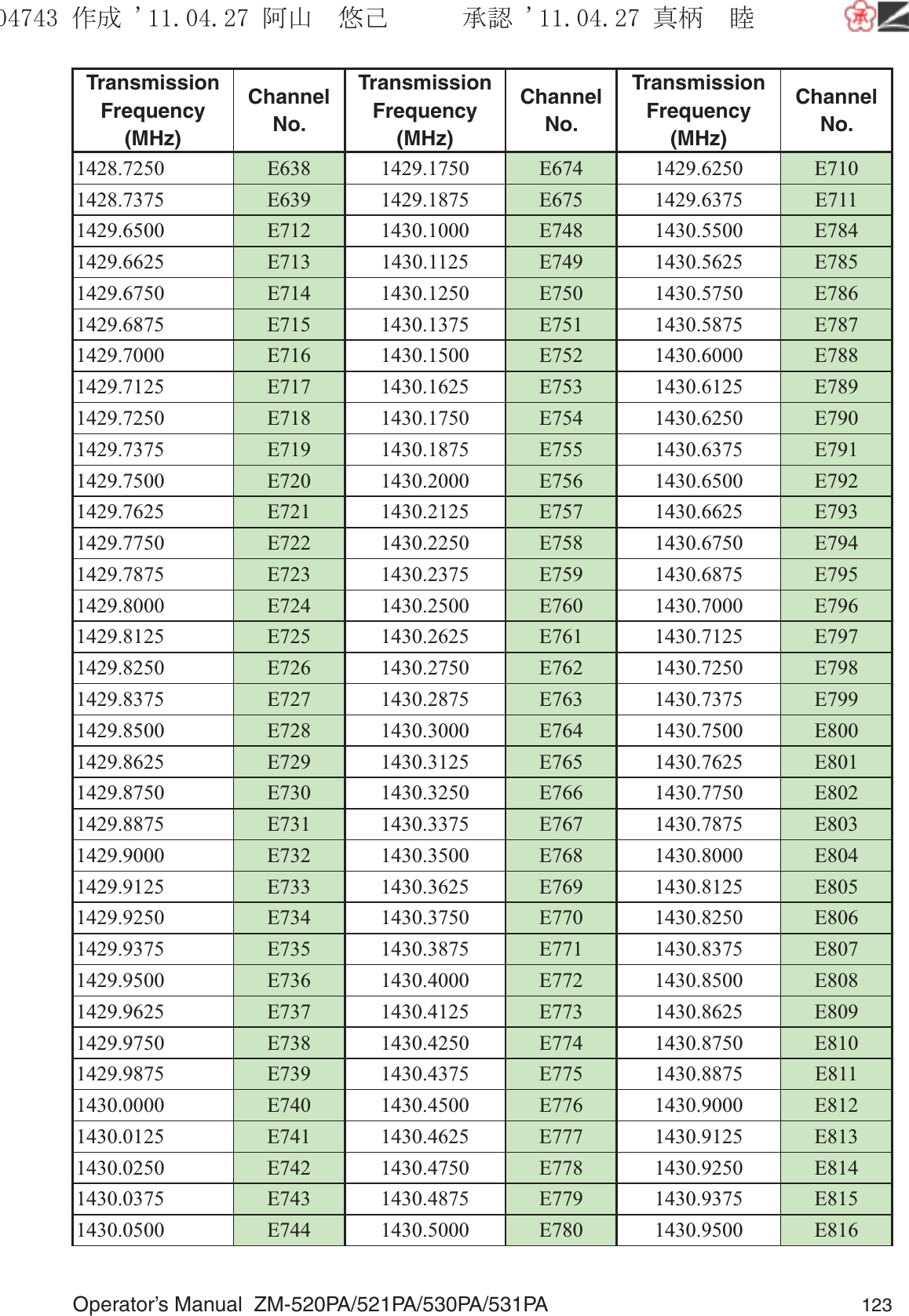
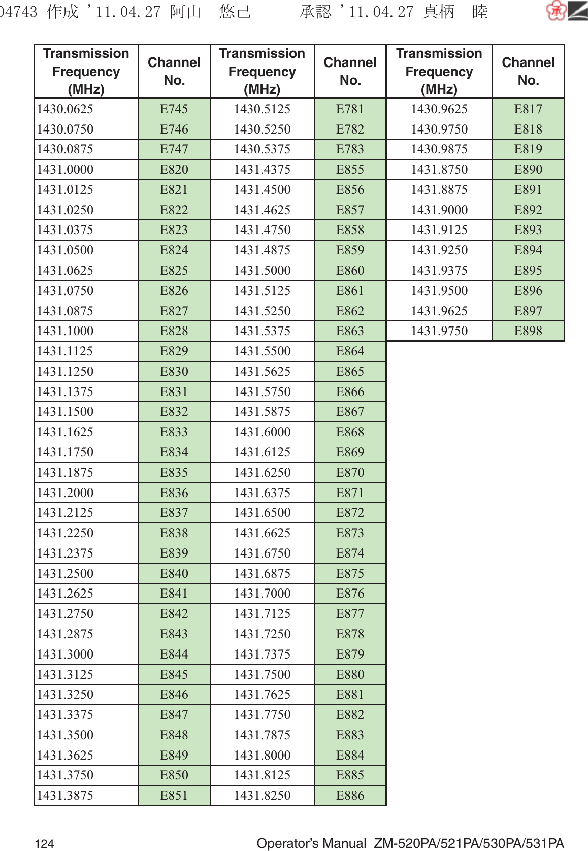
Nihon Kohden ZM-531PA WMTS TRANSMITTER User Manual
Nihon Kohden Corporation WMTS TRANSMITTER
UserManual.wiki
>
Nihon Kohden
>
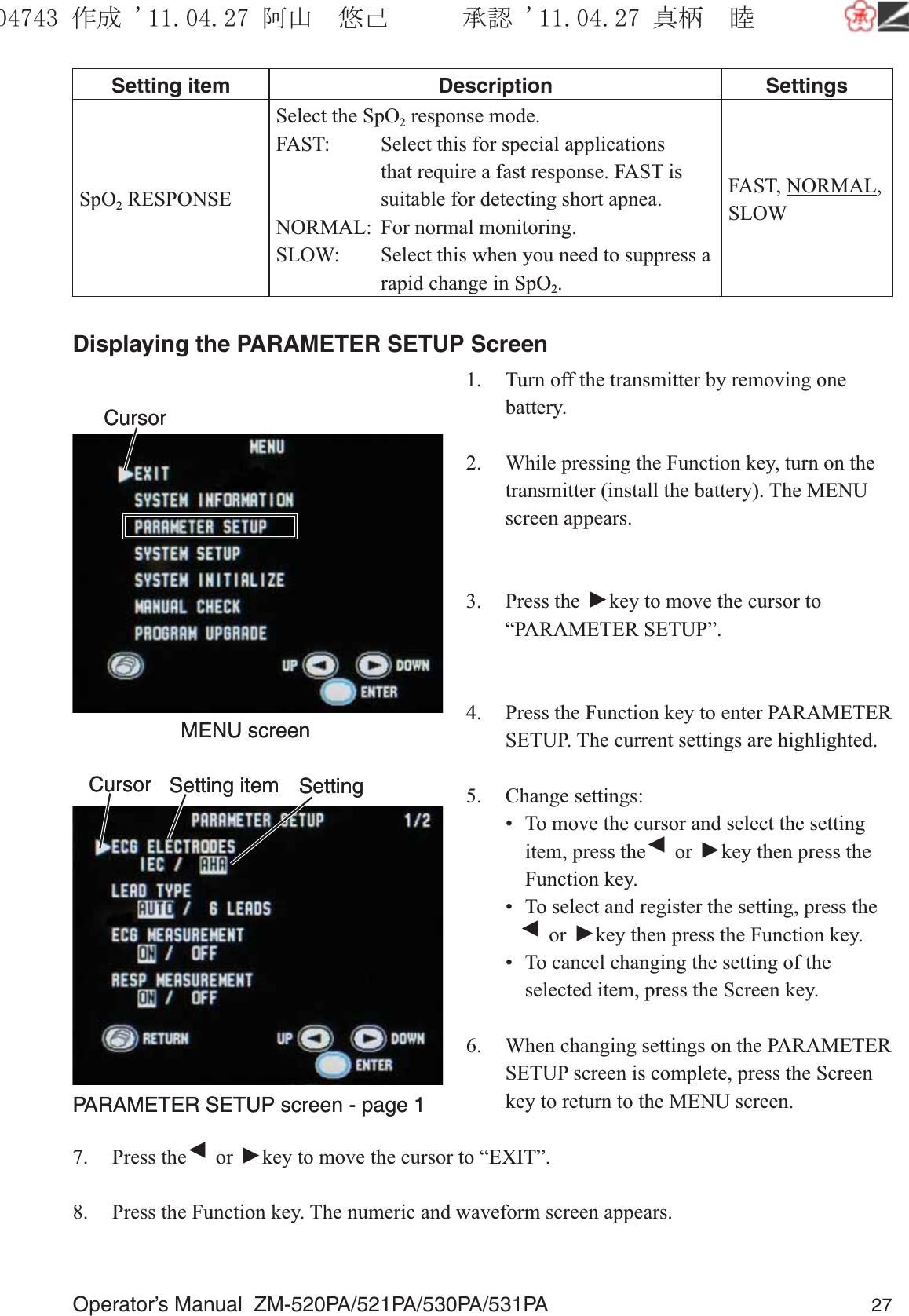
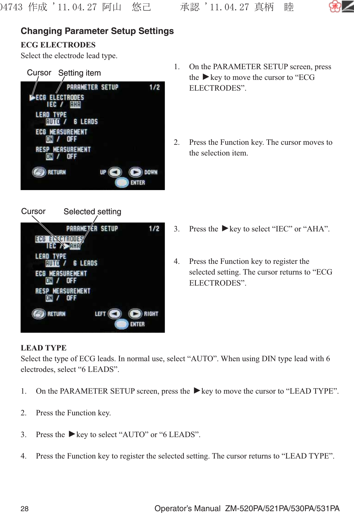
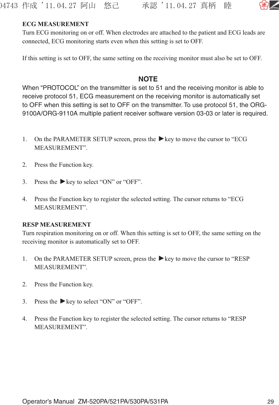
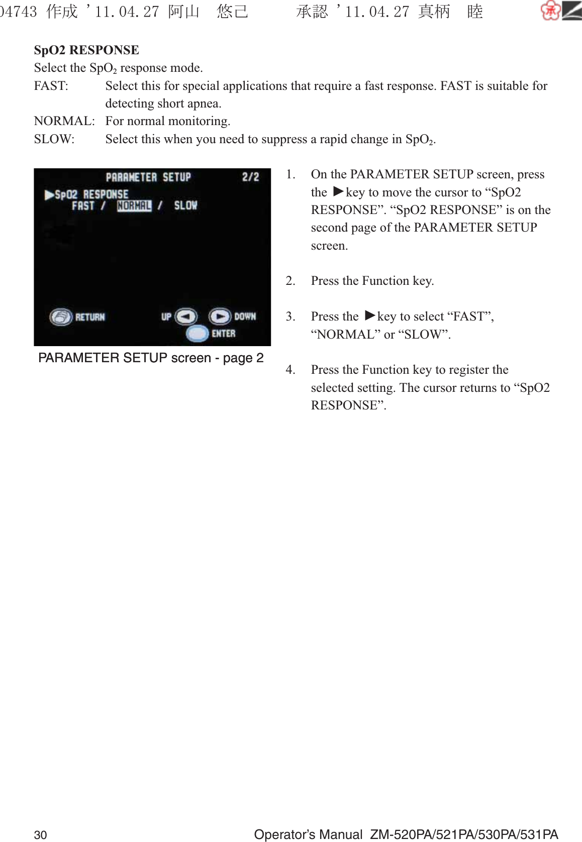
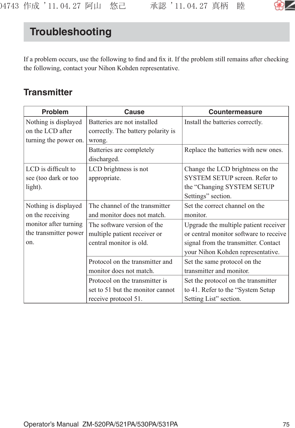
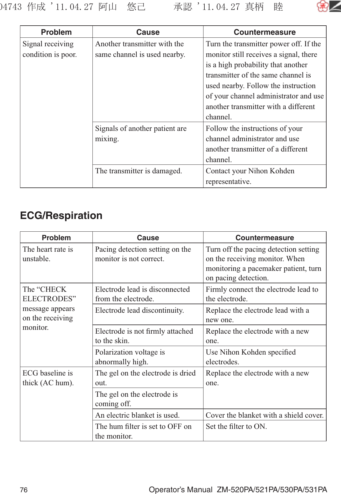
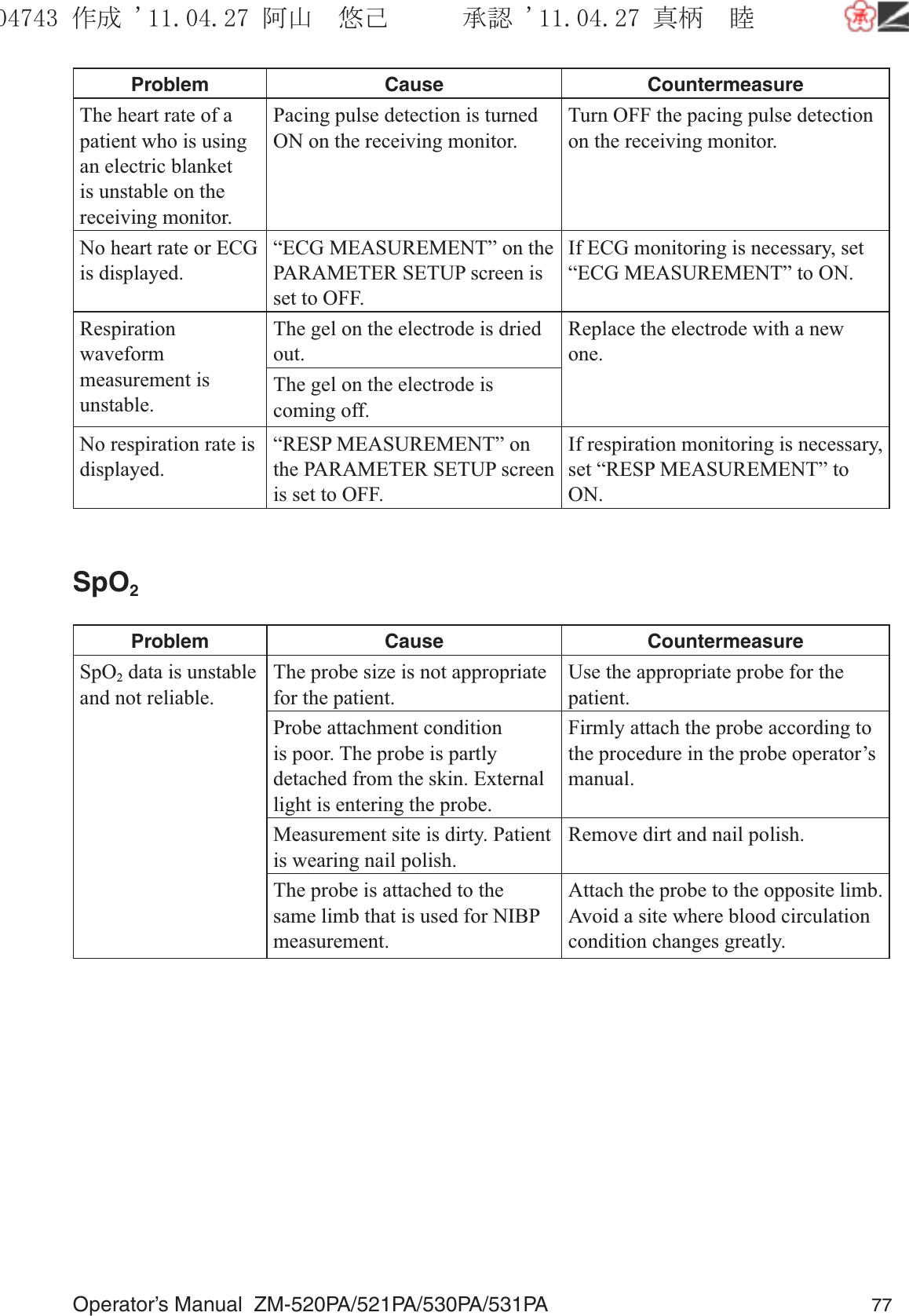
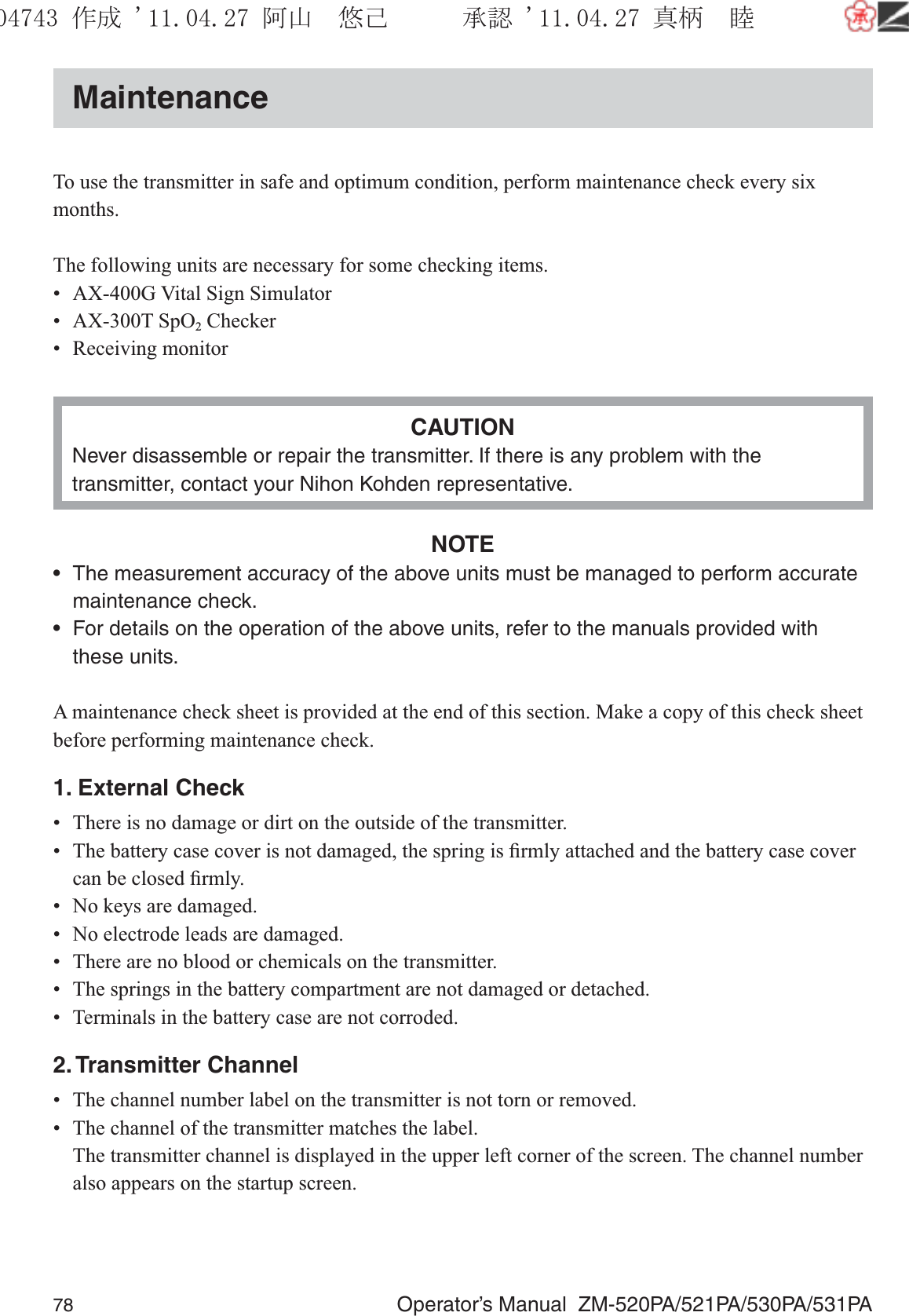
ZM 531PA User Manual
User Manual
Navigation menu
Upload a User Manual
Namespaces
Wiki Guide
HTML
PDF
Info
Views
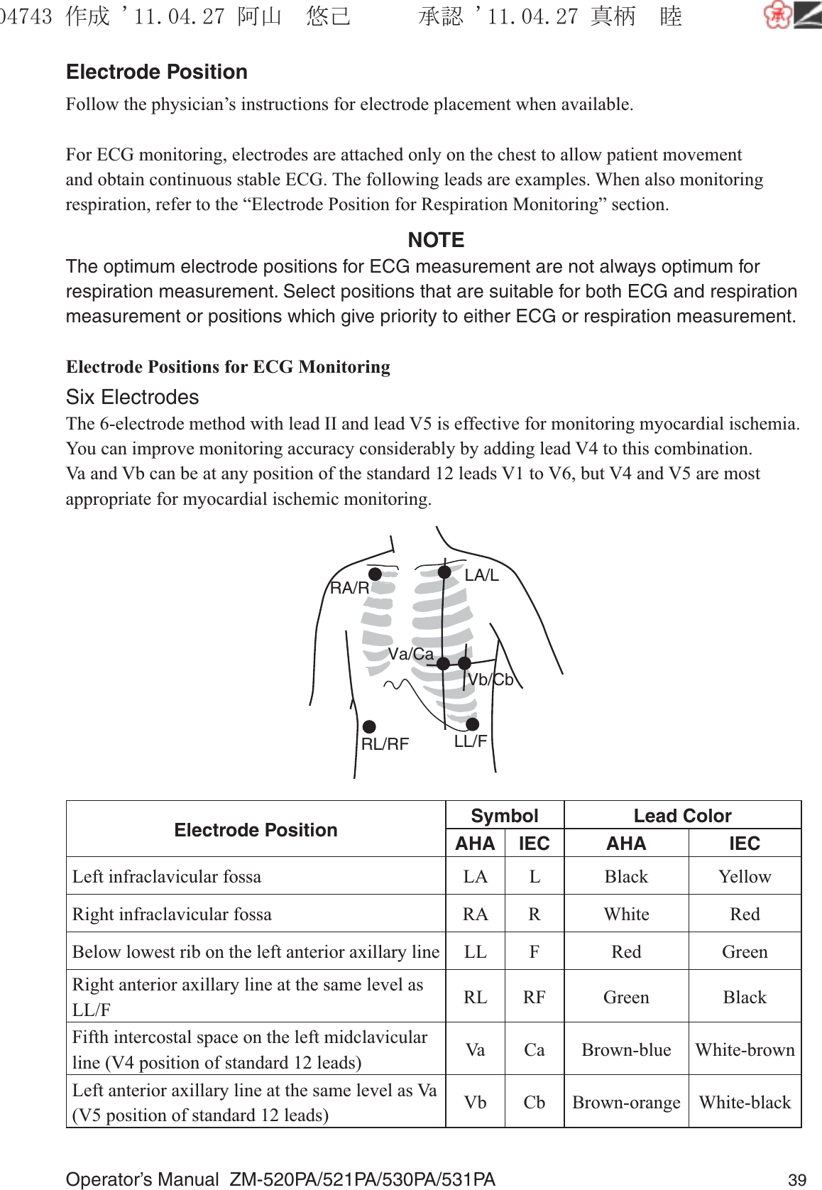
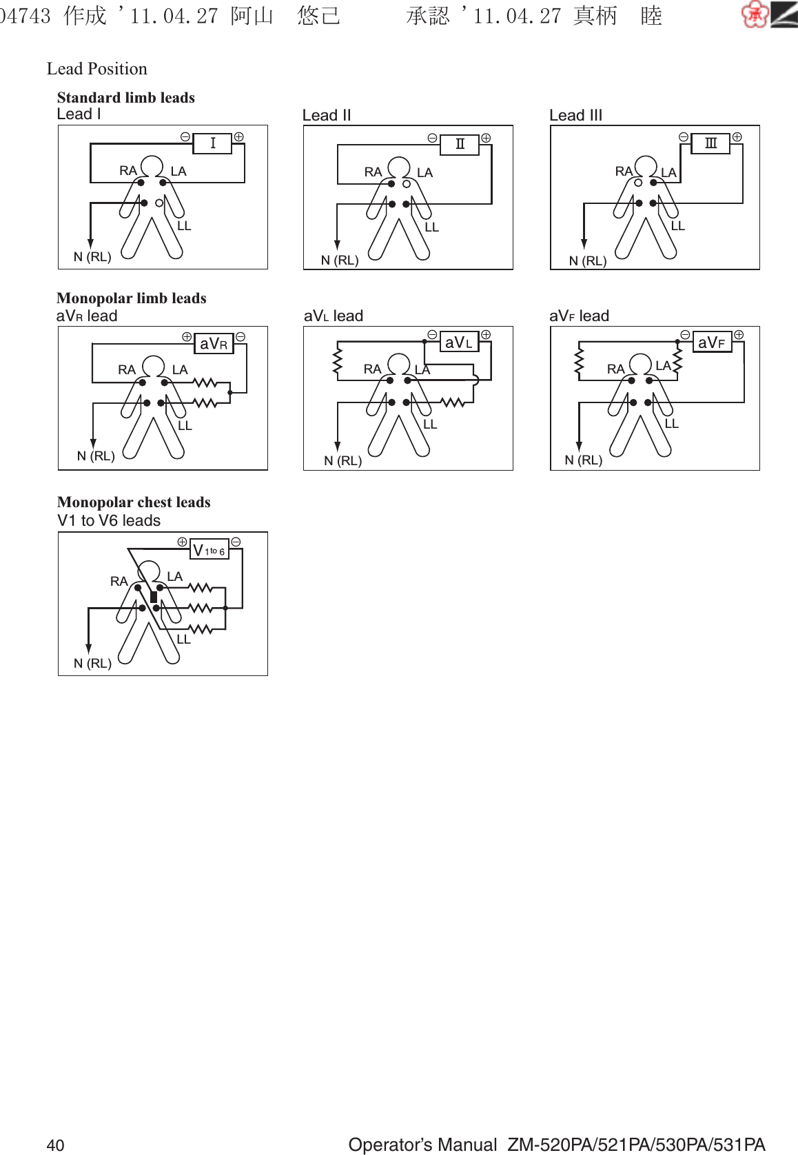
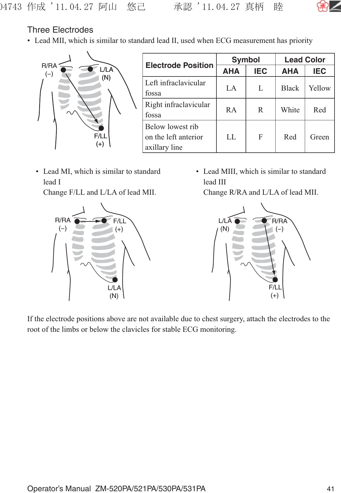
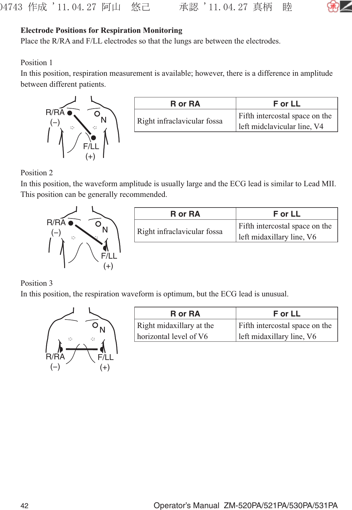
User Manual
Discussion / Help
Navigation