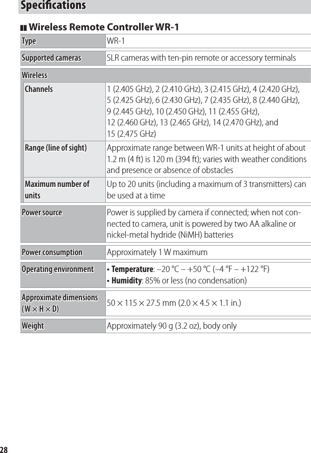
Nikon 4149EA Wireless Remote Controller User Manual
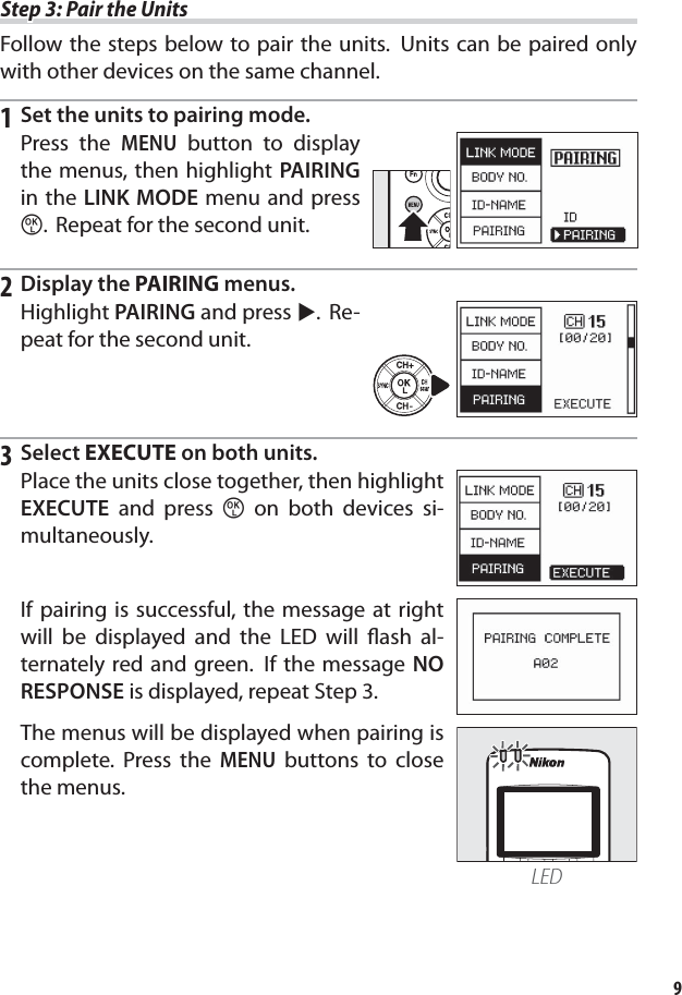
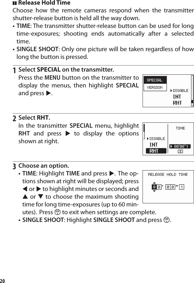
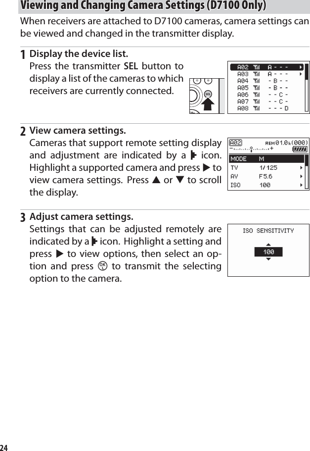
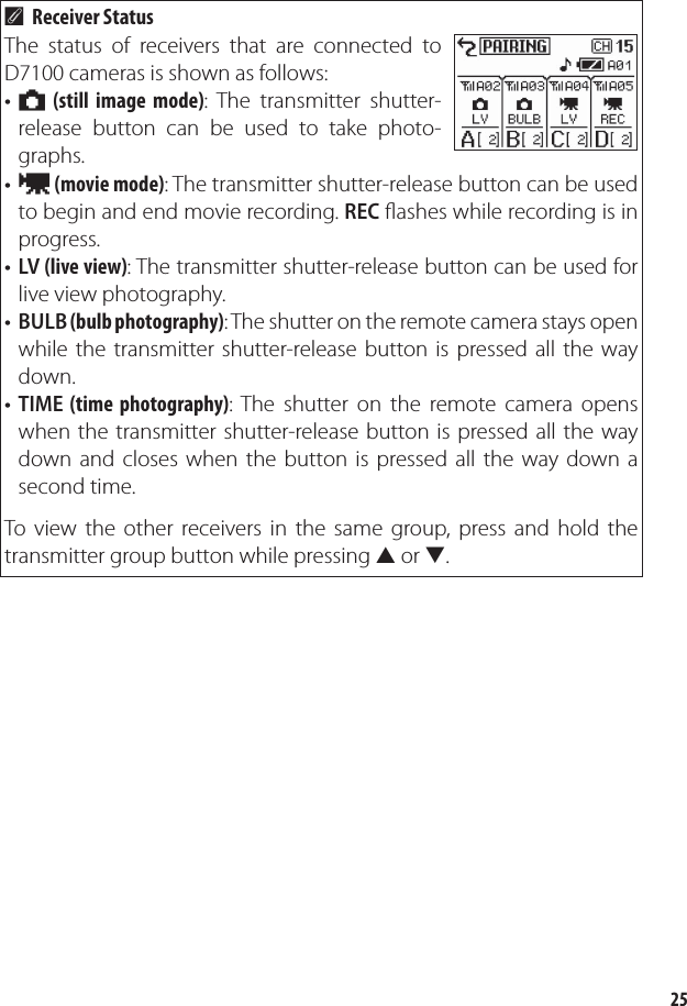
Nikon Corporation Wireless Remote Controller
UserManual.wiki
>
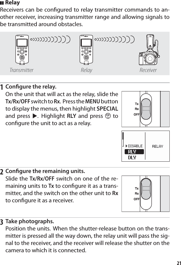
Nikon
>
4149EA User Manual
User Manual
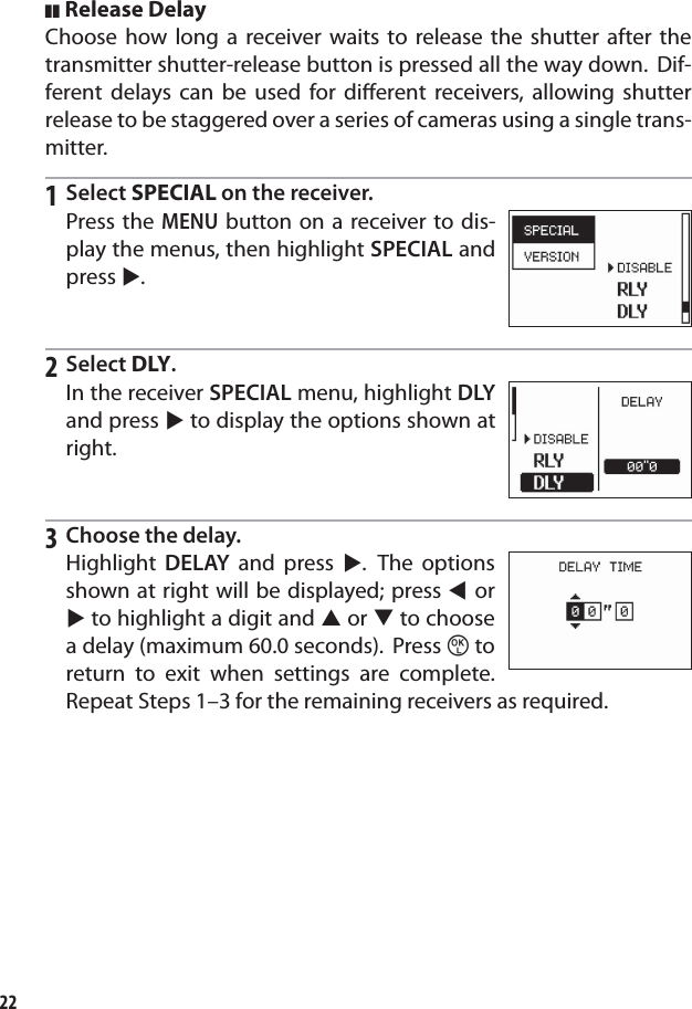
Navigation menu
Upload a User Manual
Namespaces
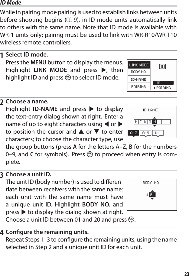
Wiki Guide
HTML
PDF
Info
Views
User Manual
Discussion / Help
Navigation