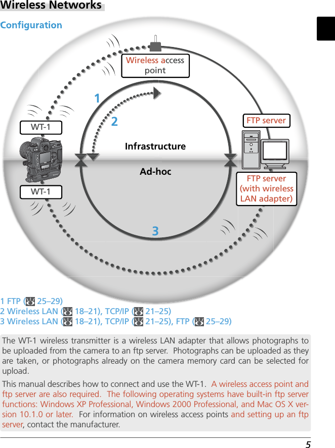
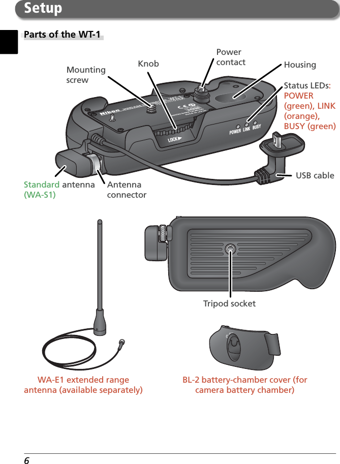
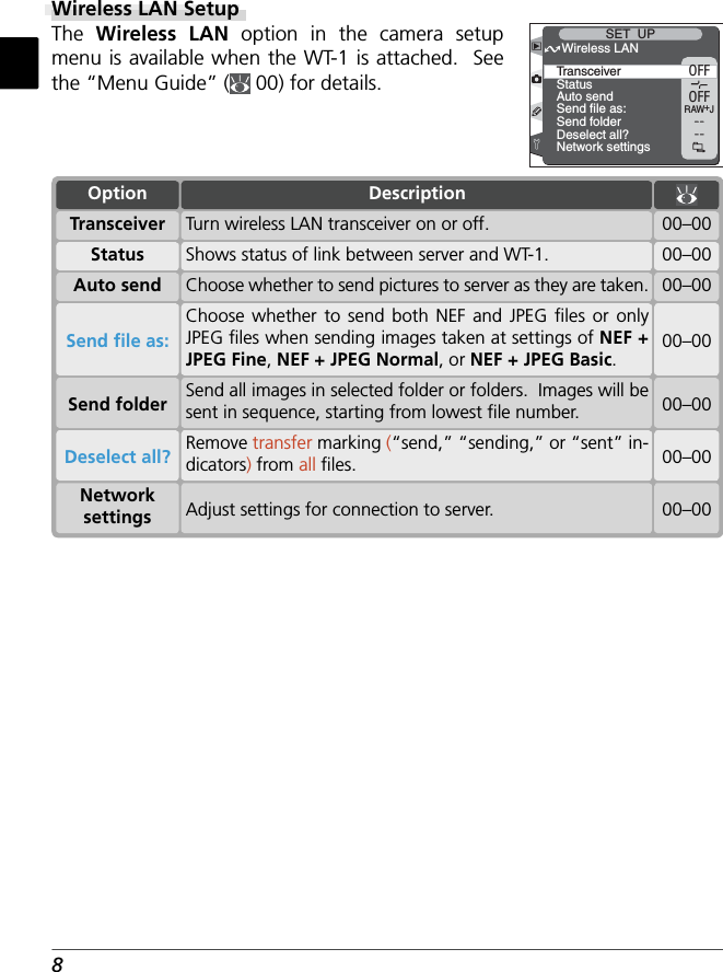
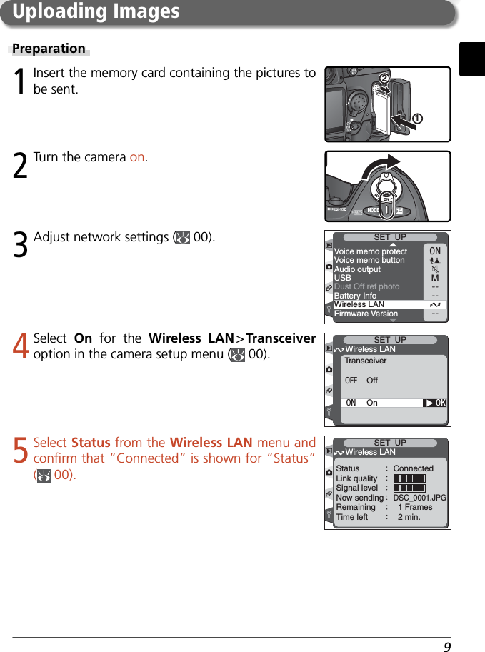
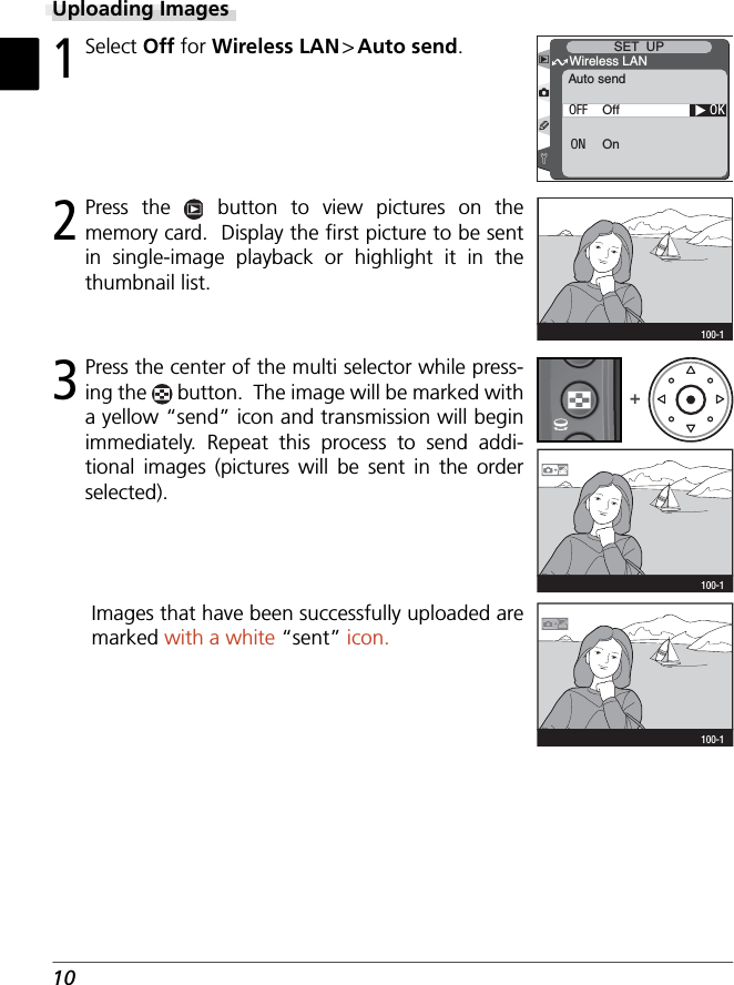
Nikon WT01 Camera with WLAN User Manual Manual
Nikon Corporation Camera with WLAN Manual
UserManual.wiki
>
Nikon
>
WT01 User Manual
Manual
Navigation menu
Upload a User Manual
Namespaces
Wiki Guide
HTML
PDF
Info
Views
User Manual
Discussion / Help
Navigation


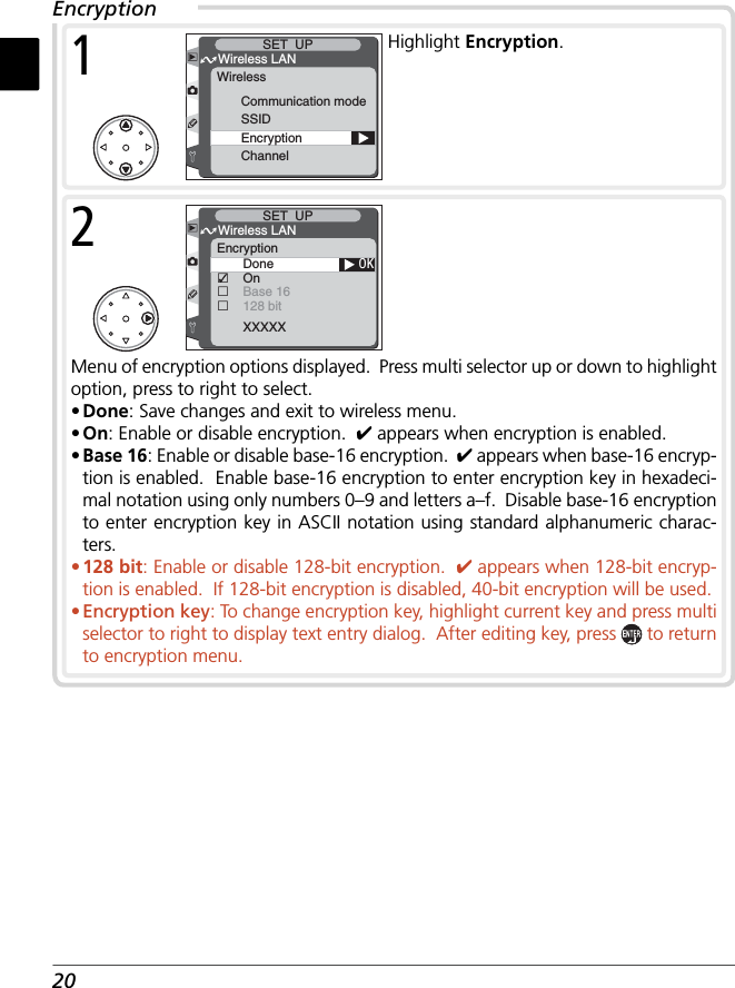
![19Communication ModeTo choose a mode according to how the wireless net-work is set up, highlight Communication mode in the wireless menu and press the multi selector to the right. Press the multi selector up or down to highlight the desired option and press to make a selection and return to the wireless menu.OKWireless LANSET UPCommunication modeInfrastructureAd-hocOptionAd-hoc Direct peer-to-peer wireless connection to ftp server.Infrastructure(default) Connection to wireless network is via access point.DescriptionSSID*Communication modeSSIDEncryptionChannelWireless LANSET UPWireless3Enter BSS- or ESS-ID for wireless access point or ftp server (see documentation provided with network adapter or con-tact network administrator). Press to return to SSID.Wireless LANSET UPSSID1Highlight current ID.* Required fi eld. Enter “ANY” to allow network to set SSID automatically.!"#$%&'()*+,–./0123456789 : ; <=>?@ABCDEFGH I J KLMNOPQRSTUVWXYZ []_abcdefghi j k lmnopq r s t uvwxy z { }+SET UPcursor OKInput2Display text entry dialog ( 00).](https://usermanual.wiki/Nikon/WT01/User-Guide-349950-Page-21.png)
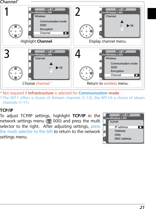
![25MAC AddressThis fi eld lists the twelve-digit Media Access Control (MAC) address for the WT-1.FTPTo adjust ftp (fi le transfer protocol) settings, highlight FTP in the network settings menu ( 00) and press the multi selector to the right. After adjusting set-tings as described below, press the multi selector to the left to return to the network settings menu.ServerUserProxyAdvancedWireless LANSET UPFTP00-00-00-00-00-00Wireless LANSET UPMAC addressServer** Required.FolderAddressWireless LANSET UPServer1Highlight Address.!"#$%&'()*+,–./0123456789 : ; <=>?@ABCDEFGH I J KLMNOPQRSTUVWXYZ []_abcdefghi j k lmnopq r s t uvwxy z { }+SET UPcursor OKInput2Display text entry dialog ( 00).FolderAddressWireless LANSET UPServer3Enter address of ftp server (if unsure of correct address, contact server admin-istrator). Press button to return to server menu.](https://usermanual.wiki/Nikon/WT01/User-Guide-349950-Page-27.png)
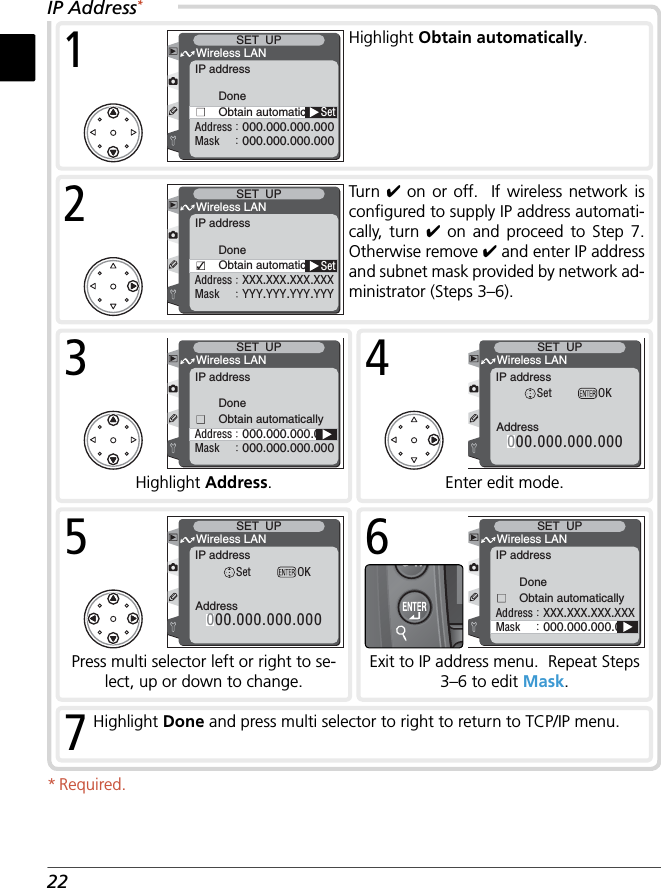
![26FolderAddressXXX.XXX.XXX. . .Wireless LANSET UPServer !"#$%&'()*+,–./0123456789 : ; <=>?@ABCDEFGH I J KLMNOPQRSTUVWXYZ []_abcdefghi j k lmnopq r s t uvwxy z { }+SET UPcursor OKInput5Display text entry dialog ( 00).4Highlight Folder.FolderAddressXXX.XXX.XXX. . .Wireless LANSET UPServer6After entering name of destination folder on ftp server, press button to return to server menu.7Highlight Done and press multi selector to left to return to ftp menu.](https://usermanual.wiki/Nikon/WT01/User-Guide-349950-Page-28.png)
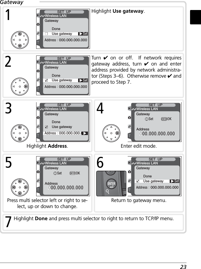
![27PasswordUser IDWireless LANSET UPUser1Highlight User ID.!"#$%&'()*+,–./0123456789 : ; <=>?@ABCDEFGH I J KLMNOPQRSTUVWXYZ []_abcdefghi j k lmnopq r s t uvwxy z { }+SET UPcursor OKInput2Display text entry dialog ( 00).PasswordUser IDWireless LANSET UPUser3After entering user name for login to ftp server, press button to return to user menu.PasswordUser IDXXXXXWireless LANSET UPUser4Highlight Password.!"#$%&'()*+,–./0123456789 : ; <=>?@ABCDEFGH I J KLMNOPQRSTUVWXYZ []_abcdefghi j k lmnopq r s t uvwxy z { }+SET UPcursor OKInput5Display text entry dialog ( 00).PasswordUser IDXXXXXWireless LANSET UPUser6After entering password for login to ftp server, press button to return to user menu. Password will be disguised as row of dots when displayed in ftp menu. 7Highlight Done and press multi selector to left to return to ftp menu.* Required.User*](https://usermanual.wiki/Nikon/WT01/User-Guide-349950-Page-29.png)