Manual

En
User's Manual
Wireless Transmitter
LOCK
POWER
LINK BUSY

Table of Contents
Introduction................................................................................................. 1
Declaration of Conformity ........................................................................ 1
For Your Safety........................................................................................... 2
WARNINGS ................................................................................................ 3
Symbols and Conventions .........................................................................4
Notices ........................................................................................................ 4
Wireless Networks .....................................................................................5
Confi guration ............................................................................................ 5
Setup............................................................................................................ 6
Parts of the WT-1 ....................................................................................... 6
Attaching the WT-1.................................................................................... 7
Wireless LAN Setup....................................................................................8
Uploading Images.......................................................................................9
Preparation ................................................................................................ 9
Uploading Images....................................................................................10
Interrupting Transmission ......................................................................... 11
“Send,” “Sending,” and “Sent” Icons ..................................................... 12
Network Status ........................................................................................ 13
Menu Guide............................................................................................... 15
Transceiver................................................................................................ 15
Status ........................................................................................................ 15
Auto Send.................................................................................................16
Send Folder ..............................................................................................16
Send File As: .............................................................................................16
Deselect All...............................................................................................17
Network Settings .....................................................................................17
Load Settings File ..................................................................................... 18
Wireless ................................................................................................... 18
TCP/IP ...................................................................................................... 21
FTP .......................................................................................................... 25
Appendices ................................................................................................ 30
Glossary .................................................................................................... 30
Specifi cations ...........................................................................................32
Index ......................................................................................................... 33

1
Thank you for purchasing a WT-1 wireless transmitter for compatible Nikon
digital cameras. When connected to the camera, the WT-1 can be used to
transmit images from the camera memory card to a server.
This manual describes how to transmit images from the camera to a server
via wireless LAN. Before using the WT-1, be sure to read the “Declaration of
Conformity” (pp. 1–2) and “For Your Safety” (pp. 2–3).
Declaration of Conformity
U.S.A. Federal Communications Commission (FCC)
Declaration of Conformity
This device complies with Part 15 of the FCC rules. Operation of the device is subject
to the following two conditions:
1. This device may not cause harmful interference, and
2. This device must not accept any interference that may cause undesired operation.
Products that contain a radio transmitter
are labeled with FCC ID and may also carry
the FCC logo.
Introduction
WT-1
FCC Radio Frequency Interference Statement
This equipment has been tested and found to comply with the limits for a Class B digi-
tal device, pursuant to Part 15 of the FCC rules. These limits are designed to provide
reasonable protection against harmful interference in a residential installation. This
equipment generates, uses, and can radiate radio frequency energy and, if not installed
and used in accordance with the instructions, may cause harmful interference to radio
communications. However, there is no guarantee that interference will not occur in a
particular installation. If this equipment does cause harmful interference to radio or
television reception, which can be determined by turning the equipment off and on,
the user is encouraged to try to correct the interference by one or more of the follow-
ing measures:
• Reorient or relocate the receiving antenna.
• Increase the separation between the equipment and receiver.
• Connect the equipment into an outlet on a circuit different from that to which the
receiver is connected.
• Consult the dealer or an experienced radio/television technician for help.
This device complies with the FCC RF exposure requirements.

2
CAUTION
Modifi cations
The FCC requires the user to be notifi ed that any changes or modifi cations made to
this device that are not expressly approved by Nikon Corporation may void the user’s
authority to operate the equipment.
Notice for customers in the State of California, U.S.A.
WARNING: Handling the cord on this product will expose you to lead, a chemical known
to the State of California to cause birth defects or other reproductive harm. Wash
hands after handling.
Nikon Inc.,
1300 Walt Whitman Road, Melville, New York
11747-3064, U.S.A.
Tel.: 631-547-4200
For Your Safety
To prevent damage to your Nikon product or injury to yourself or to others,
read the following safety precautions in their entirety before using this equip-
ment. Keep these safety instructions where all those who use the product
will read them.
The consequences that could result from failure to observe the precautions
listed in this section are indicated by the following symbol:
This icon marks warnings, information that should be read before using this
Nikon product to prevent possible injury.
3
WARNINGS
Do not disassemble
Failure to observe this precaution could result in fi re, electric shock, or other injury. Should the
product break open as the result of a fall or other accident, disconnect the camera power source
and take the product to a Nikon-authorized service representative for inspection.
Turn camera off immediately in the event of malfunction
Should you notice smoke or an unusual smell coming from the equipment, immediately remove
the battery from the camera, taking care to avoid burns. Continued operation could result in
injury. After removing the battery, take the equipment to a Nikon-authorized service represen-
tative for inspection.
Keep dry
Do not immerse in or expose to water or rain. Failure to observe this precaution could result in
fi re or electric shock.
Do not use in the presence of fl ammable gas
Failure to observe this precaution could result in explosion or fi re.
Do not handle with wet hands
Failure to observe this precaution could result in electric shock.
Keep out of reach of children
Failure to observe this precaution could result in injury.
Follow the instructions of hospital and airline personnel
This device emits radio frequency radiation that could interfere with medical or navigational
equipment. Do not use this device in a hospital or on board an airplane without fi rst obtaining
the permission of hospital or airline staff.
Do not expose to high temperatures
Do not leave the device in a closed vehicle under the sun or in other areas subject to extremely
high temperatures. Failure to observe this precaution could result in fi re or in damage to the
casing or internal parts.
Observe caution when using the WA-E1
When using the WA-E1 Extended Range Antenna (available separately), be careful not to put
the tip of the antenna in your eye accidentally. Failure to observe this precaution could result in
blindness or other visual impairment.
Trademark Information
Mac OS is a reg is tered trade mark of Apple Computer, Inc. Internet is a trademark of Digital Equipment Corporation.
Microsoft and Win dows are reg is tered trade marks of Microsoft Corporation. All oth er trade names men tioned in
this man u al or the oth er doc u men ta tion pro vid ed with this Nikon prod uct are trade marks or reg is tered trade marks
of their re spec tive holders.

4
This icon indicates that more infor-
mation is available elsewhere in this
manual.
This icon marks notes, information
that should be read before using
the device.
Notices
• No part of the manuals included with this
product may be reproduced, transmitted,
transcribed, stored in a retrieval system,
or translated into any language in any
form, by any means, without Nikon’s
prior written permission.
• Nikon reserves the right to change the
specifi cations of the hardware and soft-
ware described in these manuals at any
time and without prior notice.
• Nikon will not be held liable for any
damages resulting from the use of this
product.
• While every effort has been made to en-
sure that the information in these manu-
als is accurate and complete, we would
appreciate it were you to bring any errors
or omissions to the attention of the Nikon
representative in your area (address pro-
vided separately).
Symbols and Conventions
The following symbols and conventions are used throughout this manual:
Life-Long Learning
As part of Nikon’s “Life-Long Learning” commitment to ongoing prod uct sup port and
ed u ca tion, con tin u al ly-updated information is avail able on-line at the following sites:
• For users in the U.S.A.: http://www.nikonusa.com/
Visit these sites to keep up-to-date with the latest product in for ma tion, tips, an swers to
fre quent ly-asked ques tions (FAQs), and gen er al advice on digital imaging and pho tog -
ra phy. Ad di tion al information may be available from the Nikon rep re sen ta tive in your
area. See the URL below for contact in for ma tion:
http://www.nikon-image.com/eng/
5
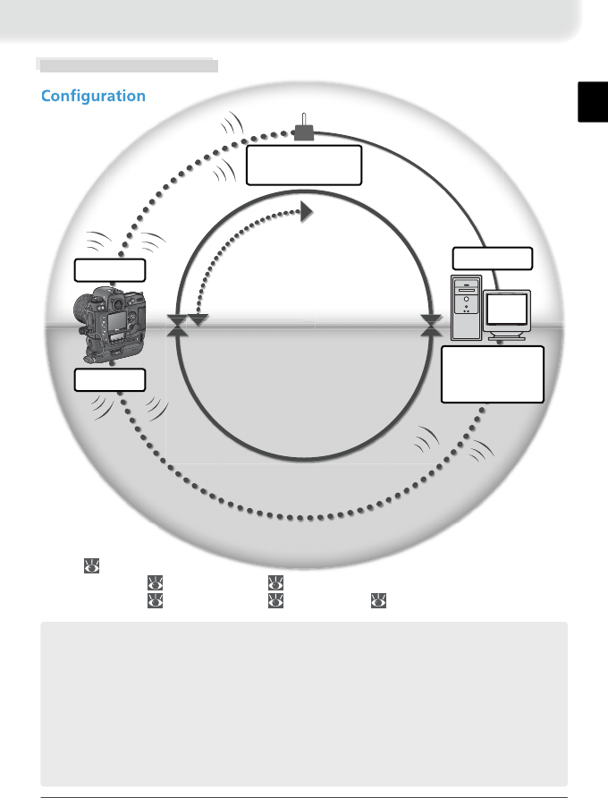
Wireless Networks
C
The WT-1 wireless transmitter is a wireless LAN adapter that allows photographs to
be uploaded from the camera to an ftp server. Photographs can be uploaded as they
are taken, or photographs already on the camera memory card can be selected for
upload.
This manual describes how to connect and use the WT-1. A wireless access point and
ftp server are also required. The following operating systems have built-in ftp server
functions: Windows XP Professional, Windows 2000 Professional, and Mac OS X ver-
sion 10.1.0 or later. For information on wireless access points and setting up an ftp
server, contact the manufacturer.
1 FTP ( 25–29)
2 Wireless LAN ( 18–21), TCP/IP ( 21–25)
3 Wireless LAN ( 18–21), TCP/IP ( 21–25), FTP ( 25–29)
Wireless access
point
FTP server
(with wireless
LAN adapter)
FTP server
LOCK
POWERLINKBUSY
C
S
C
L
A/V
OUT
DC
IN
POWERLINKBUSY
WT-1
WT-1
Infrastructure
Ad-hoc
3
2
1
6
Setup
LOCK
POWER
LINK BUSY
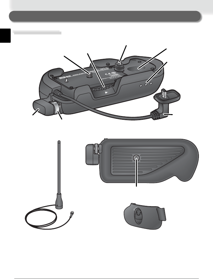
Knob
Mounting
screw
Standard antenna
(WA-S1)
Antenna
connector
Tripod socket
USB cable
Status LEDs:
POWER
(green), LINK
(orange),
BUSY (green)
Housing
Power
contact
Parts of the WT-1
WA-E1 extended range
antenna (available separately)
BL-2 battery-chamber cover (for
camera battery chamber)
7
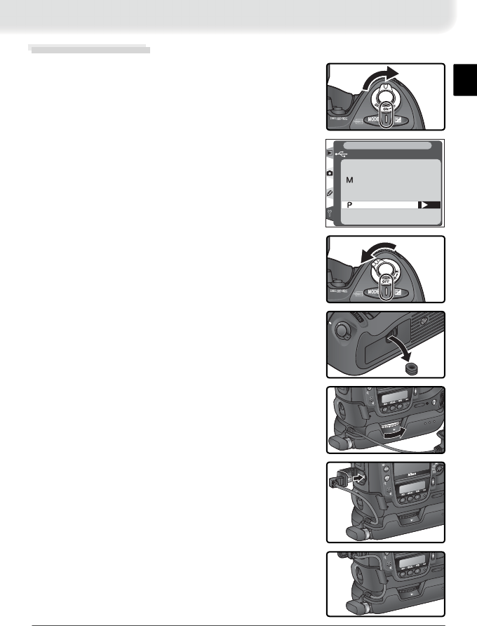
2 Before connecting the WT-1, set the USB option
in the camera setup menu to PTP.
1 Turn the camera on.
3 Turn the camera off.
5 Place the camera on the WT-1 and rotate the knob
in the direction shown to fasten the WT-1 to the
camera tripod mount.
4 Remove the cover protecting the camera power
contact.
6 Connect the USB cable to the camera USB con-
nector.
7 Pass cable over guide on BL-2 battery-chamber
cover.
OK
USB
Mass Storage
PTP
SET UP
LOCK
POWER
LINKBUSY
POWER
LINKBUSY
LOCK
POWER
POWER
Attaching the WT-1
LOCK
POWER
POWER
8
Wireless LAN Setup
The Wireless LAN option in the camera setup
menu is available when the WT-1 is attached. See
the “Menu Guide” ( 00) for details. OFF
RAW+J
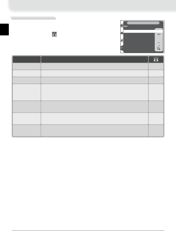
OFF
Tra ns ceiver
Wireless LAN
Status
Auto send
Send file as:
Send folder
Deselect all?
Network settings
SET UP
Auto send
Transceiver
Status
Option
Shows status of link between server and WT-1.
Turn wireless LAN transceiver on or off.
Choose whether to send pictures to server as they are taken.
Description
00–00
00–00
Send fi le as:
Choose whether to send both NEF and JPEG fi les or only
JPEG fi les when sending images taken at settings of NEF +
JPEG Fine, NEF + JPEG Normal, or NEF + JPEG Basic.
00–00
Send folder Send all images in selected folder or folders. Images will be
sent in sequence, starting from lowest fi le number. 00–00
00–00
Deselect all? Remove transfer marking (“send,” “sending,” or “sent” in-
dicators) from all fi les. 00–00
Network
settings Adjust settings for connection to server. 00–00
9
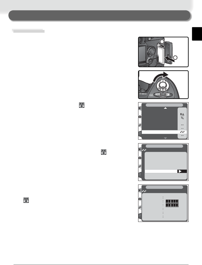
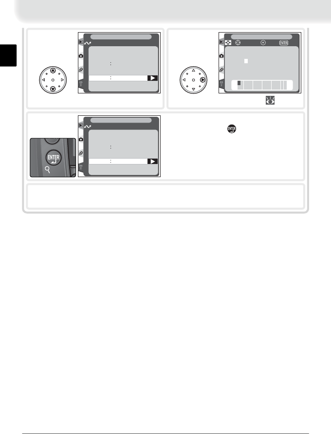
3 Adjust network settings ( 00).
Preparation
1 Insert the memory card containing the pictures to
be sent.
1
2
2 Turn the camera on.
ON
M
Voice memo protect
Voice memo button
Audio output
USB
Battery Info
Wireless LAN
Firmware Version
SET UP
Dust Off ref photo
4 Select On for the Wireless LAN > Transceiver
option in the camera setup menu ( 00).
Uploading Images
5 Select Status from the Wireless LAN menu and
confi rm that “Connected” is shown for “Status”
( 00).
OK
Transceiver
Wireless LAN
SET UP
Off
On
OFF
ON
SET UP
Wireless LAN
Status Connected
Link quality
Signal level
Now sending
DSC_0001.JPG
Remaining 1 Frames
Time left 2 min.
10
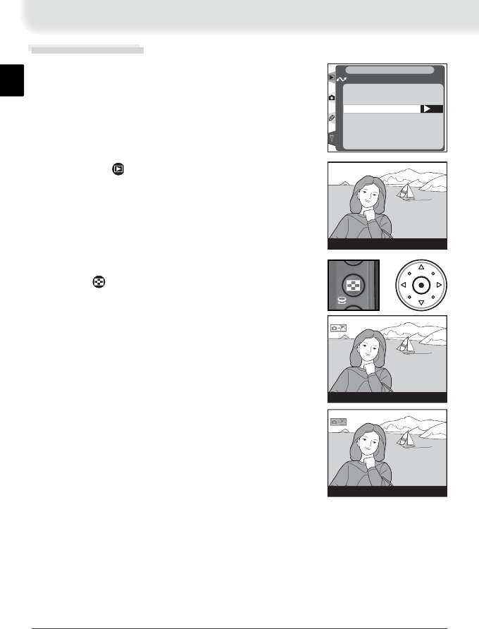
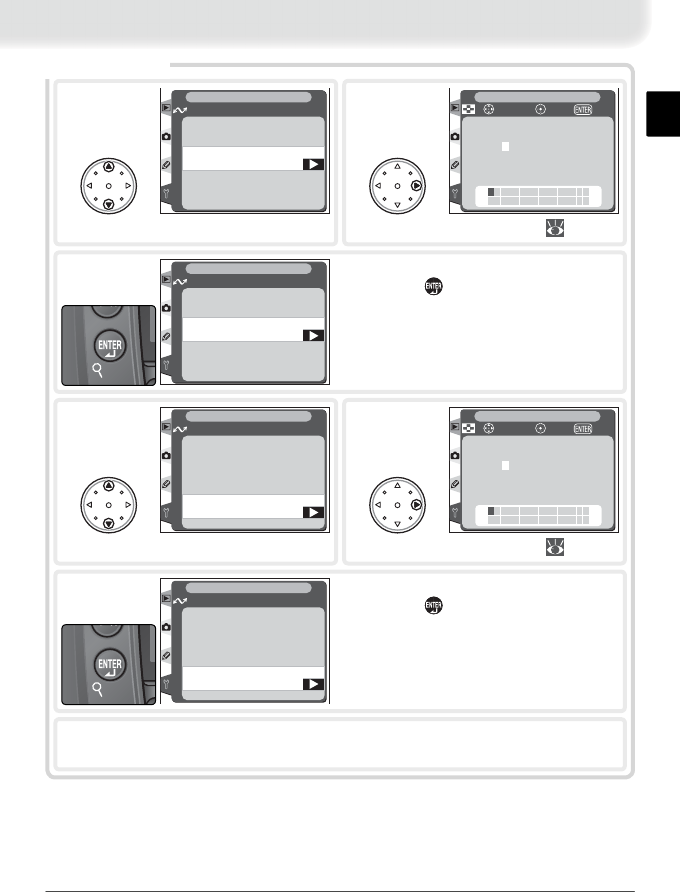
3 Press the center of the multi selector while press-
ing the button. The image will be marked with
a yellow “send” icon and transmission will begin
immediately. Repeat this process to send addi-
tional images (pictures will be sent in the order
selected).
Uploading Images
1 Select Off for Wireless LAN > Auto send.
OK
Auto send
Wireless LAN
SET UP
Off
On
OFF
ON
2 Press the button to view pictures on the
memory card. Display the fi rst picture to be sent
in single-image playback or highlight it in the
thumbnail list.
100-1
100-1
+
100-1
Images that have been successfully uploaded are
marked with a white “sent” icon.

11
Interrupting Transmission
To cancel transmission of images marked with a “send” icon, select the im-
ages during playback and press the center of the multi selector while pressing
the button. The “send” icon will be removed. Any of the following actions
will also interrupt transmission:
• Turning the camera off
• Choosing Off in the Wireless LAN > Transceiver menu
• Selecting Deselect all? in the Wireless LAN menu
• Deleting the images by pressing the button while the images are se-
lected
• Formatting the memory card
Loss of Signal
Transmission may be interrupted if the signal is lost ( 000). Transmission can be
resumed by turning the camera off and then on again, activating the camera exposure
meters, or selecting On for Wireless LAN > Transceiver once the signal is restored.
Turning the Camera Off
“Send” marking will be saved if the camera is turned off or Off is selected for Wireless
LAN > Transceiver while transmission is in progress. Transmission of images marked
with a “send” icon will resume when the camera is turned on or On is selected for
Wireless LAN > Transceiver.
Voice Memos
Voice memos can not be uploaded separately, but will be included when the associated
pictures are transmitted.
12
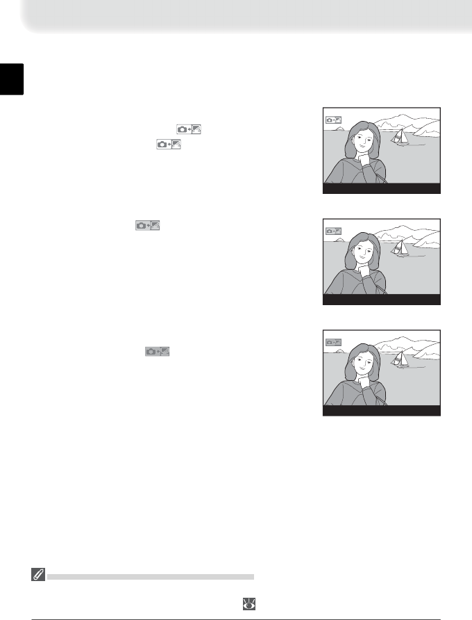
“Send,” “Sending,” and “Sent” Icons
The following icons are displayed when images selected for upload are viewed
during playback.
“Send”
Images that have been selected for upload are marked
with a yellow “send” icon ( ). If the image is sent
successfully, the yellow icon will turn white.
100-1
“Sending”
During upload, the icon is displayed in red.
100-1
Removing “Send” and “Sent” Indicators
“Send,” “sending,” and “sent” indicators can be removed from all images by selecting
Delete tags from the Wireless LAN menu ( 000).
“Sent”
Images that have been uploaded successfully are
marked with a white icon.
100-1
13
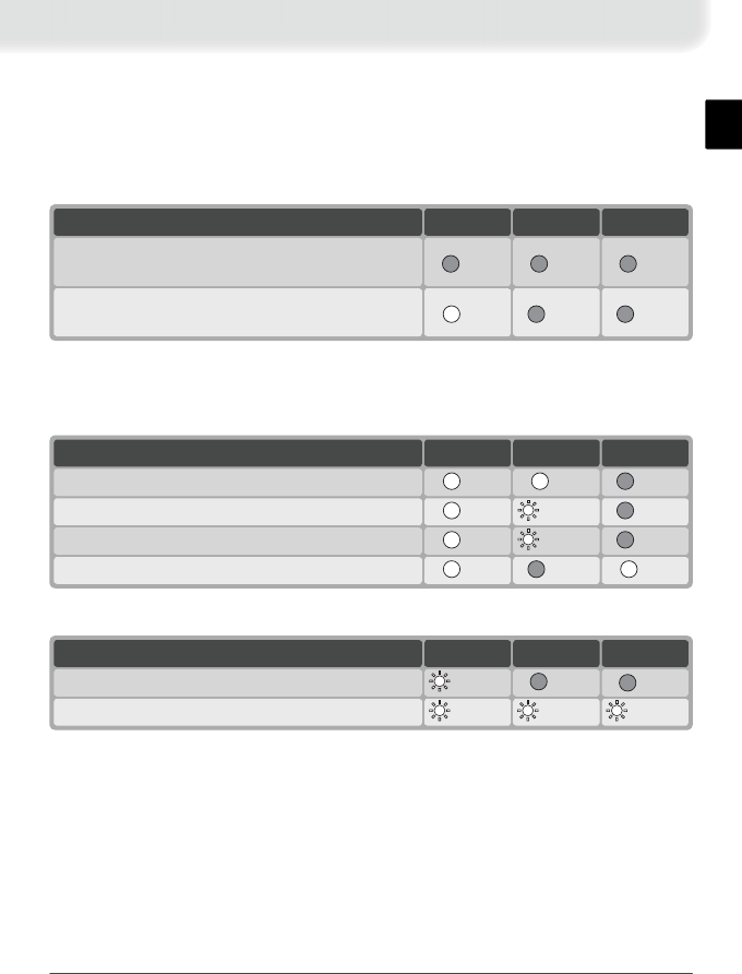
Network Status
The status of the link between the server and the WT-1 is shown by the status
LEDs and by the Status display in the Wireless LAN menu.
The Status LEDs
The POWER LED lights when the WT-1 is receiving power from the camera.
(off) (off) (off)
Camera or exposure meters off, or Off selected
for Wireless LAN > Transceiver
(off)* (off)†
(on)
Camera and exposure meters on, and On select-
ed for Wireless LAN > Transceiver
BUSYLINKPOWERStatus
BUSYLINKPOWERStatus
(off) (off) (blinks)Connection error
(blinks) (blinks) (blinks)WT-1 hardware malfunction
BUSYLINKPOWERStatus
(on) (off)*
(on)Data remaining
(off)†
(blinks) (on)Sending data
(off)†
(on) (on)Connecting to server
(off)†
(blinks) (on)Connected to server
The status of the link between the WT-1 and the server is shown by the LINK
LED, which blinks at different speeds to indicate link quality. The BUSY LED
lights when data remain to be sent.
The following indicate that an error has occurred:
* Lights while connecting to server, blinks once connected
† Lights if data remain to be sent
14
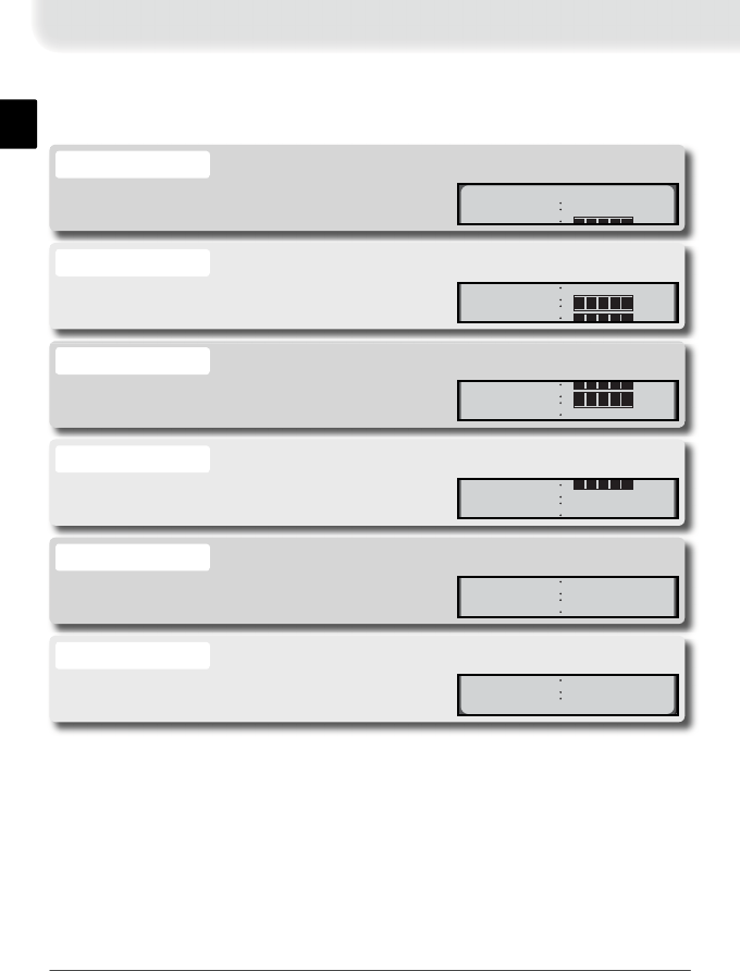
The Status Display
Network status can also be viewed by selecting Status from the Wireless
LAN menu.
The status of the link between the server and the
camera.
Status
Status Connected
Link quality
A fi ve-level indicator of link quality.
Link quality
Status Connected
Link quality
Signal level
Estimated time required to send remaining data.
Time left
Remaining
1
Frames
Time left 2 min.
The number of fi les remaining to be sent.
Remaining
Now
sending
DSC
_
0001
.
JPG
Remaining 1 Frames
Time left 2 min
The name of the fi le currently being sent.
Now sending
Si
gna
l
l
eve
l
Now sending
DSC_0001.JPG
Remaining 1Frames
A fi ve-level indicator of signal strength.
Signal level
Link
quality
Signal level
Now sending
DSC 0001 JPG
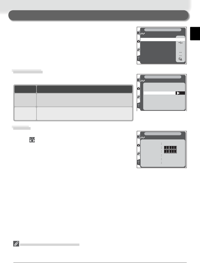
15
This section describes the options available in the
Wireless LAN sub-menu of the camera setup menu.
OFF
RAW+J
OFF
Tra n s ceiver
Wireless LAN
Status
Auto send
Send file as:
Send folder
Deselect all?
Network settings
SET UP
Option Description
Transceiver off. Camera can not communicate
with server.
Off
(default)
Transceiver on. Camera can communicate
with server.
On
Transceiver
Turn the WT-1 transceiver on or off.
OK
Transceiver
Wireless LAN
SET UP
Off
On
OFF
ON
Menu Guide
Turning the Transceiver On
Transmission of images marked with a “send” icon begins as soon as On is selected for
Wireless LAN > Transceiver.
Status
Current status of the link between the WT-1 and the
server ( 00).
SET UP
Wireless LAN
Status Connected
Link quality
Signal level
Now sending
DSC_0001.JPG
Remaining 1 Frames
Time left 2 min.
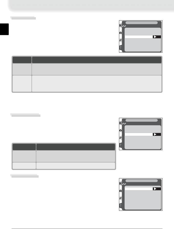
16
Auto Send
Choose whether to upload pictures to the server as
they are taken.
OK
Auto send
Wireless LAN
SET UP
Off
On
OFF
ON
Option
On
Pictures are uploaded to server as they are taken.* Transmission begins
as soon as picture has been recorded to camera memory card. Be sure
memory card is inserted in camera before shooting.
Off
(default)
Pictures are not automatically uploaded to server as they are taken. Pic-
tures can be selected for transmission when camera is in playback mode.
Description
* Pictures will not be uploaded to the server if Off is selected in the Wireless
LAN > Transceiver menu. Pictures will instead be marked with a “send” indicator as
they are recorded to the memory card.
Send File As:
When sending images taken at settings of NEF +
JPEG Fine, NEF + JPEG Normal, or NEF + JPEG
Basic, choose whether to send both NEF (RAW) and
JPEG fi les or only the JPEG fi les. OK
Send file as:
Wireless LAN
SET UP
NEF + JPEG
JPEG only
Send Folder
Entire folders can be selected for transmission to the
server. The selected folder and all fi les it contains
(including those already marked as “sent”) will be
uploaded in ascending order by fi le number. Trans-
mission begins when the folder is selected.
OK
100NCD2H
Wireless LAN
SET UP
Option
JPEG only Send JPEG fi les only.
NEF + JPEG
(default) Send both NEF (RAW) and JPEG fi les.
Description
17
Deselect All
Remove “send,” “sending,” and “sent” marking
from all images on the memory card.
OK
Wireless LAN
SET UP
Deselect all?
No
Ye s
Option
Yes Remove “send,” “sending,“ and “sent”
marking from all images.
No
(default)
“Send,” “sending,” and “sent” marking is
not removed.
Description
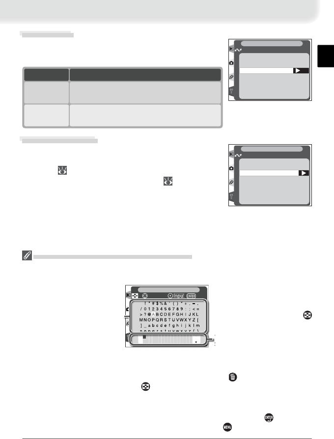
Network Settings
Adjust settings for connection to the server. Settings
created using a computer can be loaded from a mem-
ory card ( 00), or network settings can be adjusted
individually using the camera menus ( 00).
Load settings file?
Wireless
TCP/IP
FTP
Wireless LAN
SET UP
Network settings
Text Entry in the “Network Settings” Menu
If text entry is required to complete the selected setting, the following dialog will be
displayed.
Keyboard area
Use multi selector to high-
light letters, press center
to select.
Text display area
Text appears in this area.
To move cursor, press
while using up, down, left,
and right buttons on multi
s
e
l
ector
.
+
SET UP
cursor OK
Use the multi selector to highlight the desired character in the keyboard area and press
the center of the multi selector to insert the highlighted character at the current cursor
position. To delete the character under the cursor, press the button. To move the
cursor to a new position, press the button while using the multi selector. No more
than thirty-six characters can be entered; if additional characters are entered when the
display is full, all characters after the thirty-sixth will be deleted.
To complete entry and return to the Network settings menu, press the button. To
exit to the setup menu without completing text entry, press .
18
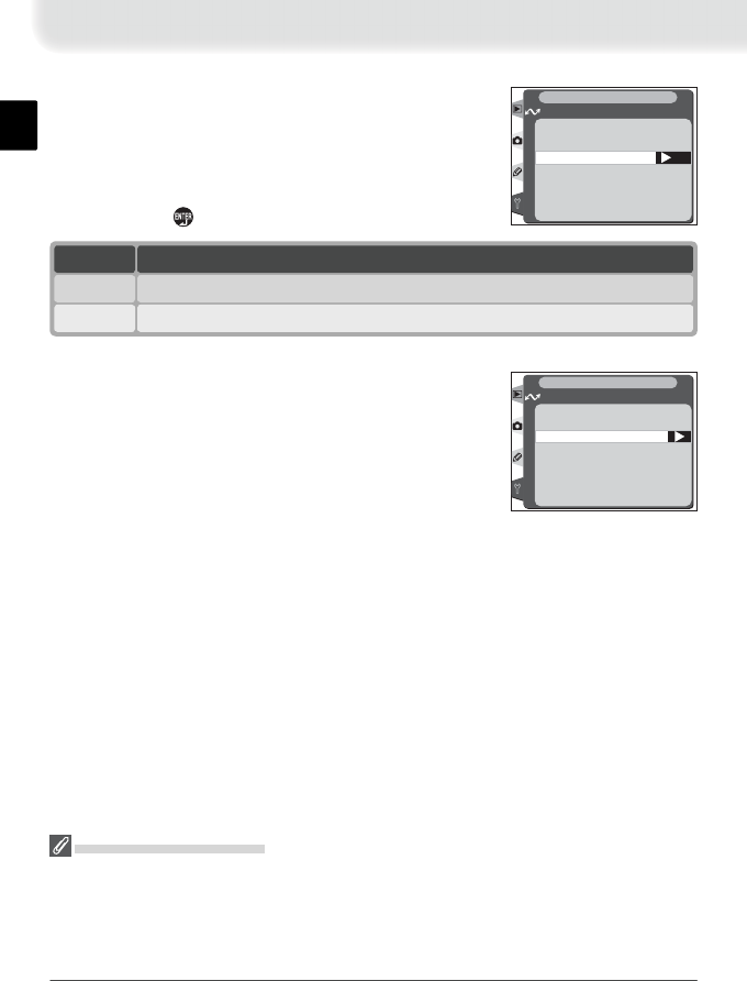
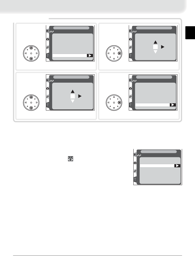
Load Settings File
Network settings created with a computer can be
saved to the camera memory card. To load these set-
tings into the camera, highlight Load settings fi le?
and press the multi selector to the right. Press the
multi selector up or down to highlight the desired op-
tion and press to make a selection.
OK
Wireless LAN
SET UP
Load settings file?
No
Ye s
Creating a Settings File
An application for creating settings fi les is available from the web sites listed on page 4
of this manual. After creating a settings fi le, save it to the root directory of the camera
memory card using a CompactFlash card reader or PCMCIA memory card adapter. No
more than one settings fi le should be stored on the memory card at a time. Additional
information is available from the download site.
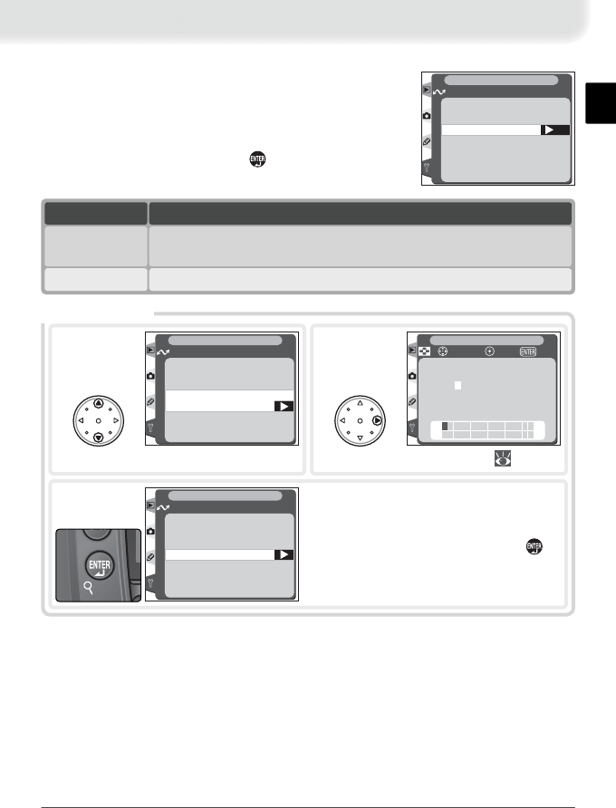
Wireless
To adjust wireless network settings, highlight Wire-
less and press the multi selector to the right. After
adjusting settings as described on the following
pages, press the multi selector to the left to return to
the network settings menu.
Communication mode
SSID
Encryption
Channel
Wireless LAN
SET UP
Wireless
Option
Yes Load Wireless, TCP/IP, and FTP settings from the memory card.
No Exit without changing settings.
Description
19
Communication Mode
To choose a mode according to how the wireless net-
work is set up, highlight Communication mode in
the wireless menu and press the multi selector to the
right. Press the multi selector up or down to highlight
the desired option and press to make a selection
and return to the wireless menu.
OK
Wireless LAN
SET UP
Communication mode
Infrastructure
Ad-hoc
Option
Ad-hoc Direct peer-to-peer wireless connection to ftp server.
Infrastructure
(default) Connection to wireless network is via access point.
Description
SSID*
Communication mode
SSID
Encryption
Channel
Wireless LAN
SET UP
Wireless
3Enter BSS- or ESS-ID for wireless access
point or ftp server (see documentation
provided with network adapter or con-
tact network administrator). Press to
return to SSID.
Wireless LAN
SET UP
SSID
1
Highlight current ID.
* Required fi eld. Enter “ANY” to allow network to set SSID automatically.
!"#$%&'()*+,–.
/0123456789 : ; <=
>?@ABCDEFGH I J KL
MNOPQRSTUVWXYZ [
]_abcdefghi j k lm
nopq r s t uvwxy z { }
+
SET UP
cursor OKInput
2
Display text entry dialog ( 00).
20
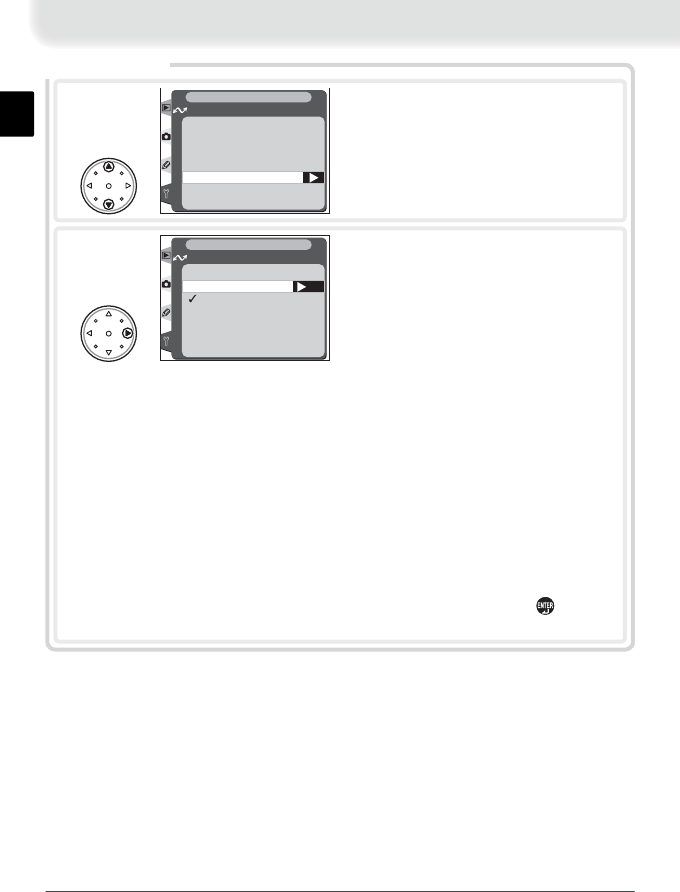
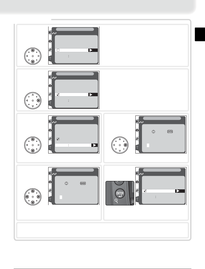
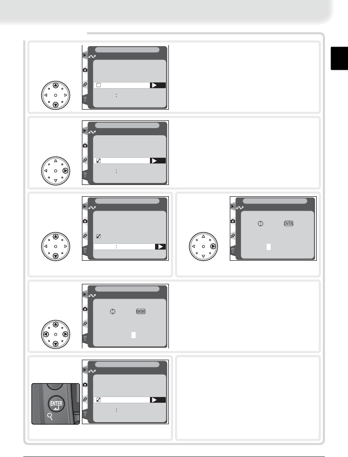
Encryption
Menu of encryption options displayed. Press multi selector up or down to highlight
option, press to right to select.
• Done: Save changes and exit to wireless menu.
• On: Enable or disable encryption. ✔ appears when encryption is enabled.
• Base 16: Enable or disable base-16 encryption. ✔ appears when base-16 encryp-
tion is enabled. Enable base-16 encryption to enter encryption key in hexadeci-
mal notation using only numbers 0–9 and letters a–f. Disable base-16 encryption
to enter encryption key in ASCII notation using standard alphanumeric charac-
ters.
• 128 bit: Enable or disable 128-bit encryption. ✔ appears when 128-bit encryp-
tion is enabled. If 128-bit encryption is disabled, 40-bit encryption will be used.
• Encryption key: To change encryption key, highlight current key and press multi
selector to right to display text entry dialog. After editing key, press to return
to encryption menu.
OK
Done
On
Base 16
128 bit
□
□
□
XXXXX
Wireless LAN
SET UP
Encryption
2
Communication mode
SSID
Encryption
Channel
Wireless LAN
SET UP
Wireless
1Highlight Encryption.
21
* Not required if Infrastructure is selected for Communication mode.
† The WT-1 offers a choice of thirteen channels (1-13), the WT-1A a choice of eleven
channels (1-11).
TCP/IP
To adjust TCP/IP settings, highlight TCP/IP in the
network settings menu ( 000) and press the multi
selector to the right. After adjusting settings, press
the multi selector to the left to return to the network
settings menu.
IP address
Gateway
DNS
MAC address
Wireless LAN
SET UP
TCP/IP
Channel*
OK
01
Wireless LAN
SET UP
Channel
2
Display channel menu.
Communication mode
SSID
Encryption
Channel
Wireless LAN
SET UP
Wireless
1
Highlight Channel.
Communication mode
SSID
Encryption
Channel
Wireless LAN
SET UP
Wireless
4
Return to wireless menu.
OK
01
Wireless LAN
SET UP
Channel
3
Choose channel.†

22
7Highlight Done and press multi selector to right to return to TCP/IP menu.
* Required.
Done
Obtain automatically
Mask
Address
000.000.000.000
000.000.000.000
Wireless LAN
SET UP
IP address
3
Highlight Address.
IP Address*
Done
Obtain automatically
Set
Mask
Address
000.000.000.000
000.000.000.000
Wireless LAN
SET UP
IP address
1Highlight Obtain automatically.
Done
Obtain automatically
Set
Mask
Address
YYY
.
YYY
.
YYY
.
YYY
XXX
.
XXX
.
XXX
.
XXX
Wireless LAN
SET UP
IP address
2Turn ✔ on or off. If wireless network is
confi gured to supply IP address automati-
cally, turn ✔ on and proceed to Step 7.
Otherwise remove ✔ and enter IP address
and subnet mask provided by network ad-
ministrator (Steps 3–6).
000.000.000.000
Address
Wireless LAN
SET UP
IP address
Set OK
4
Enter edit mode.
000.000.000.000
Address
Wireless LAN
SET UP
IP address
Set OK
5
Press multi selector left or right to se-
lect, up or down to change.
Done
Obtain automatically
Mask
Address
000.000.000.000
XXX
.
XXX
.
XXX
.
XXX
Wireless LAN
SET UP
IP address
6
Exit to IP address menu. Repeat Steps
3–6 to edit Mask.
23
7Highlight Done and press multi selector to right to return to TCP/IP menu.
Done
Use gateway
Address 000.000.000.000
Wireless LAN
SET UP
Gateway
3
Highlight Address.
Gateway
Set
Done
Use gateway
Address 000.000.000.000
Wireless LAN
SET UP
Gateway
1Highlight Use gateway.
Set
Done
Use gateway
Address 000.000.000.000
Wireless LAN
SET UP
Gateway
2Turn ✔ on or off. If network requires
gateway address, turn ✔ on and enter
address provided by network administra-
tor (Steps 3–6). Otherwise remove ✔ and
proceed to Step 7.
000.000.000.000
Set OK
Address
Wireless LAN
SET UP
Gateway
4
Enter edit mode.
000.000.000.000
Set OK
Address
Wireless LAN
SET UP
Gateway
5
Press multi selector left or right to se-
lect, up or down to change.
Set
Done
Use gateway
Address 000.000.000.000
Wireless LAN
SET UP
Gateway
6
Return to gateway menu.
24
7Highlight Done and press multi selector to right to return to TCP/IP menu.
Done
Enable DNS
Address 000.000.000.000
Wireless LAN
SET UP
DNS
3
Highlight Address.
DNS
Set
Done
Enable DNS
Address 000.000.000.000
Wireless LAN
SET UP
DNS
1Highlight Enable DNS.
Set
Done
Enable DNS
Address 000.000.000.000
Wireless LAN
SET UP
DNS
2Turn ✔ on or off. If network requires DNS
(Domain Name Server) address, turn ✔ on
and enter address provided by network
administrator (Steps 3–6). Otherwise re-
move ✔ and proceed to Step 7.
000.000.000.000
Set OK
Address
Wireless LAN
SET UP
DNS
4
Enter edit mode.
200.000.000.000
Set OK
Address
Wireless LAN
SET UP
DNS
5
Press multi selector left or right to se-
lect, up or down to change.
Set
Done
Enable DNS
Address 000.000.000.000
Wireless LAN
SET UP
DNS
6
Return to DNS menu.
25
MAC Address
This fi eld lists the twelve-digit Media Access Control
(MAC) address for the WT-1.
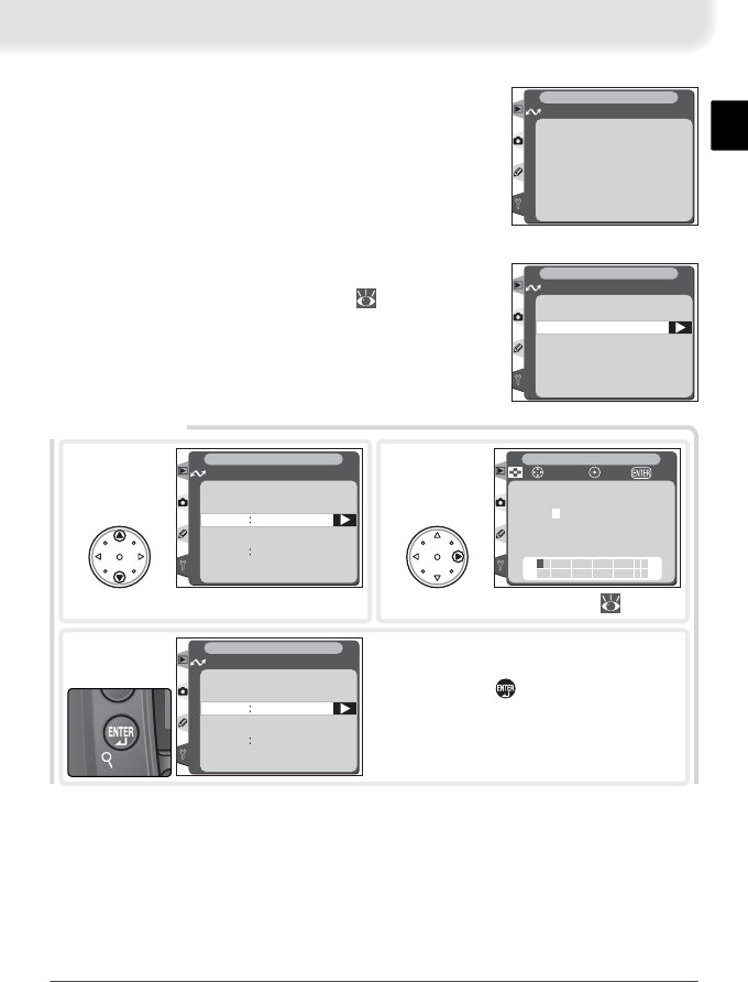
FTP
To adjust ftp (fi le transfer protocol) settings, highlight
FTP in the network settings menu ( 00) and press
the multi selector to the right. After adjusting set-
tings as described below, press the multi selector to
the left to return to the network settings menu.
Server
User
Proxy
Advanced
Wireless LAN
SET UP
FTP
00-00-00-00-00-00
Wireless LAN
SET UP
MAC address
Server*
* Required.
Folder
Address
Wireless LAN
SET UP
Server
1
Highlight Address.
!"#$%&'()*+,–.
/0123456789 : ; <=
>?@ABCDEFGH I J KL
MNOPQRSTUVWXYZ [
]_abcdefghi j k lm
nopq r s t uvwxy z { }
+
SET UP
cursor OKInput
2
Display text entry dialog ( 00).
Folder
Address
Wireless LAN
SET UP
Server
3Enter address of ftp server (if unsure of
correct address, contact server admin-
istrator). Press button to return to
server menu.
26
Folder
Address
XXX
.
XXX
.
XXX
. . .
Wireless LAN
SET UP
Server !"#$%&'()*+,–.
/0123456789 : ; <=
>?@ABCDEFGH I J KL
MNOPQRSTUVWXYZ [
]_abcdefghi j k lm
nopq r s t uvwxy z { }
+
SET UP
cursor OKInput
5
Display text entry dialog ( 00).
4
Highlight Folder.
Folder
Address
XXX
.
XXX
.
XXX
. . .
Wireless LAN
SET UP
Server
6After entering name of destination folder
on ftp server, press button to return to
server menu.
7Highlight Done and press multi selector to left to return to ftp menu.
27
Password
User ID
Wireless LAN
SET UP
User
1
Highlight User ID.
!"#$%&'()*+,–.
/0123456789 : ; <=
>?@ABCDEFGH I J KL
MNOPQRSTUVWXYZ [
]_abcdefghi j k lm
nopq r s t uvwxy z { }
+
SET UP
cursor OKInput
2
Display text entry dialog ( 00).
Password
User ID
Wireless LAN
SET UP
User
3After entering user name for login to ftp
server, press button to return to user
menu.
Password
User ID
XXXXX
Wireless LAN
SET UP
User
4
Highlight Password.
!"#$%&'()*+,–.
/0123456789 : ; <=
>?@ABCDEFGH I J KL
MNOPQRSTUVWXYZ [
]_abcdefghi j k lm
nopq r s t uvwxy z { }
+
SET UP
cursor OKInput
5
Display text entry dialog ( 00).
Password
User ID
XXXXX
Wireless LAN
SET UP
User
6After entering password for login to ftp
server, press button to return to user
menu. Password will be disguised as row
of dots when displayed in ftp menu.
7Highlight Done and press multi selector to left to return to ftp menu.
* Required.
User*

28
7Highlight Done and press multi selector to right to return to ftp menu.
Done
Use proxy server
Port
Address
0
000.000.000.000
Wireless LAN
SET UP
Proxy
3
Highlight Address.
Proxy
Set
Done
Use proxy server
Port
Address
0
000.000.000.000
Wireless LAN
SET UP
Proxy
1Highlight Use proxy server.
Set
Done
Use proxy server
Port
Address
0
000.000.000.000
Wireless LAN
SET UP
Proxy
2Turn ✔ on or off. If proxy server is re-
quired for ftp, turn ✔ on and enter ad-
dress and port number (Steps 3–6). Oth-
erwise remove ✔ and proceed to Step 7.
000.000.000.000
Set OK
Address
Wireless LAN
SET UP
Proxy
4
Enter edit mode.
200.000.000.000
Set OK
Address
Wireless LAN
SET UP
Proxy
5
Press multi selector left or right to se-
lect, up or down to change.
Done
Use proxy server
Port
Address
0
XXX
.
XXX
.
XXX
.
XXX
Wireless LAN
SET UP
Proxy
6
Return to proxy menu. Repeat steps
3–6 to enter Port number.
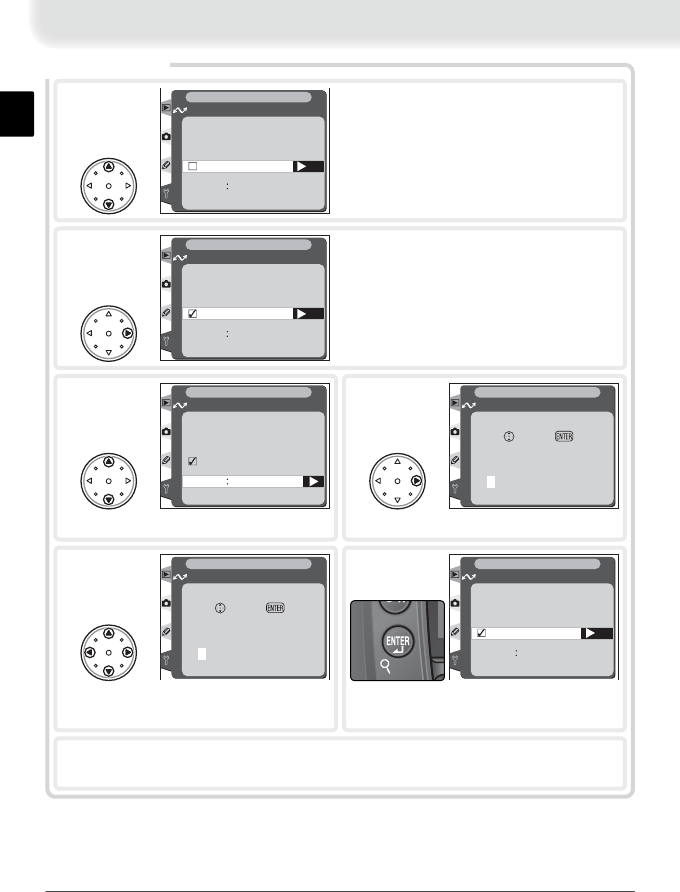
29
Done
PA SV mode
Port 0
Wireless LAN
SET UP
Advanced
3
Highlight Port.
Advanced
Set
Done
PA SV mode
Port 0
Wireless LAN
SET UP
Advanced
1Highlight PASV mode.
Set
Done
PA SV mode
Port 0
Wireless LAN
SET UP
Advanced
2Turn ✔ on or off. Turn ✔ on to instruct
ftp server to use PASV mode (be sure serv-
er supports PASV mode before turning
this option on). Turn ✔ off to use normal
(PORT) mode.
00000
Set OK
Port
Wireless LAN
SET UP
Advanced
4
Enter edit mode.
7Highlight Done and press multi
selector to right to return to ftp
menu.
Set
Done
PA SV mode
Port 21
Wireless LAN
SET UP
Advanced
6
Return to advanced menu.
00020
Set OK
Port
Wireless LAN
SET UP
Advanced
5Enter port number for ftp connection (if
required). Press multi selector left or right
to select digit, up or down to change.

30
Glossary
Ad-hoc
Devices in an ad-hoc wireless network communicate directly (“peer to peer”), without
a wireless access point. The WT-1 supports an ad-hoc mode for direct wireless connec-
tion to an ftp server.
BSS-ID (Basic Service Set ID)
All wireless devices on an ad-hoc wireless network share the same BSS-ID. The BSS-ID
may be up to thirty-two characters long and is case sensitive. See also Ad-hoc.
Channel
When multiple wireless LANs with different ESS-IDs are operating on a single frequency
within a given area, transmission speeds will drop. Specifying a separate channel (fre-
quency) for each network can prevent interference and increase transmission speeds
(note that all devices in the same network must be set to the same channel). In the
IEEE 812.11b standard, the 2.4 GHz band is divided into 14 channels, each separated
by 4 MHz.
DHCP (Dynamic Host Confi guration Protocol) Server
Each device in a TCP/IP network requires an IP address. If a DHCP server is present on
the network, IP addresses will be assigned automatically. A DHCP server will not be
present on networks that consist solely of Windows Me, Windows 98, or Windows 95
computers. DHCP may be enabled on other networks; consult the network administra-
tor or see the manual provided with the router or operating system.
ESS-ID (Extended Service Set ID)
Multiple BSSs can be confi gured to form an ESS, allowing users to roam between
wireless access points. Only devices with the same ESS-ID as a given access point can
communicate with that access point. The ESS-ID may be up to thirty-two characters
long and is case sensitive.
Infrastructure
Devices in an infrastructure network communicate via one or more wireless access
points. The WT-1 supports an infrastructure mode for connection to a wireless network
via an access point.
LAN (Local Area Network)
A network of computers located in relatively close proximity to one another. LANs
generally support data transfer speeds of 10–100 Mbps.
MAC (Media Access Control) Address
A unique hardware address for each device on a network, required when sending and
receiving packets.
Appendices

31
Protocol
A set of rules for passing information back and forth between devices in a network. By
defi ning such elements of communication as how links are established, how receipt of
a signal is acknowledged, how data are encoded, and how to handle errors, a protocol
ensures that data are transmitted without loss of information.
SS-ID
An SS-ID prevents interference between devices in different networks. See also BSS-ID,
ESS-ID.
TCP/IP (Transmission Control Protocol/Internet Protocol)
A dual protocol consisting of a transport-layer protocol (TCP) that divides data into
packets which it later reassembles, and a network protocol (IP) that handles transmis-
sion of the packets between points in the network. It can be implemented on different
platforms, allowing data to be transmitted between machines with different operating
systems.
USB (Universal Serial Bus)
A standard for connecting peripheral devices. USB supports data transfer rates of up to
480 Mbps (USB 2.0). Devices connected via USB can be connected and disconnected
with the power on (“hot plug”) and do not require separate IRQ (interrupt request)
numbers, preventing confl icts with other devices.
WEP (Wired Equivalent Privacy)
A privacy protocol intended to provided users of wireless networks with the same level
of privacy as a wired network. When using WEP, enter the encryption key provided by
the network administrator.
32
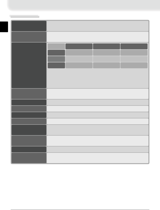
Specifi cations
IEEE 802.11b (standard wireless LAN protocol); DSSS (IEEE 802.11-
compliant); half duplex
Type
RCR STD-33, ARIB STD-T66 (standard for low power data com-
munications systems)
Standards
146.5 mm × 34.5 mm × 65.5mm (5.8˝ × 1.4˝ × 2.6˝)
Dimensions
(W × H × D)
220 g (7.8 oz)Weight
Temperature: 0–40 °C (32–131 °F)
Humidity: 20–80% (no condensation)
Operating
environment
Sleep: 9 mA maximum; receive: 185 mA maximum; send:
285 mA maximum
Power
consumption
1425 mW maximum
Power output
5 VOperating voltage
128/40-bit WEPSecurity
1, 2, 5.5, and 11 MbpsData rates
11 channels
Operating
frequency
11 Mbps
1 Mbps
2 Mbps
50 m (164´)
Indoor*
90 m (295´)
115 m (377´)
25 m (82´)
Indoor†
40 m (131´)
50 m (164´)
Outdoor
160 m (525´)
400 m (1312´)
550 m (1804´)
* Few obstacles
† Many obstacles
The presence of reinforced concrete, metal structures, or metal
furniture may result in decreased range.
Range
(line of sight)

33
Index
L
LAN, 00
LED. See Status LEDs; BUSY;
LINK; POWER
LINK, 00
Link quality, 00
Link status, 00
Load settings fi le?, 00
M
MAC address, 00
Mounting screw, 00
N
Network settings, 00
Network settings fi les, 00
P
Password, 00
POWER, 00
Power contact, 00
S
Send folder, 00
“Send” marking, 00
Send fi le as, 00
“Sending” marking, 00
“Sent” marking, 00
Settings fi les. See Network
settings fi les; Load set-
tings fi le
Signal strength, 00
Status, 00
Status. See Link status; Status
LEDs
Status LEDs, 00
Subnet mask, 00
T
TCP/IP, 00
TCP/IP, 00
Transceiver, 00
U
Upload, 00
interrupting, 00
preparing camera for, 00
selecting images for, 00
USB, 00
USB, 00
cable, 00
connector, 00
setup, 00
User ID, 00
V
Voice memos, 00
W
WEP, 00
Wireless, 00
Wireless access point, 00
Wireless LAN, 00
Wireless LAN, 00
confi guration, 00
A
Access point. See Wireless
access point
Antenna, 00
Auto send, 00
B
BSS-ID, 00
BUSY, 00
C
Channel, 00
selection, 00
Connecting the WT-1, 00
Customer support, 00
D
Deselect all?, 00
DHCP, 00
Domain Name Server (DNS)
address, 00
DNS, 00
E
Encryption, 00
key, 00
ESS-ID, 00
F
Folders, 00
FTP, 00
ftp, 00
folder, 00
password, 00
PASV mode, 00
port number, 00
proxy, 00
server, 00
settings, 00
user ID, 00
G
Gateway, 00
Gateway address, 00
I
IP address, 00