Nine Eagles Electronic Technology SR12316899 Radio Control User Manual X6 2011 04 25
Shanghai Nine Eagles Electronic Technology Co., Ltd. Radio Control X6 2011 04 25
Users Manual
X6
Operation and Instruction
of 6-channel TX

Warning
NE-T007 2.4GHz transmitter is not a toy. To ensure your safety, children under 14 years old are
strictly forbidden from operating it.
It uses 8 AA NiMH batteries, any other inapplicable batteries are strictly forbidden. If you are not
experienced in operating, we suggest you to learn it under the guidance of a well-experienced
operator. Manufacturer and distributor are exempted from the responsibility of the product usage.
We strongly suggest you to read this instruction carefully before operating.
This product has passed authoritative International Certification: America FCC, Europe CE,
ROHS, and Australia C-Tick and so on.
Caution:
Changes or modifications not expressly approved by the par ty responsible for compliance
could void the user`s.
Compliance statement:
This device complies with par t 15 of the FCC rules. Operation is subject to the following two
conditions:
1) This device may not cause harmful interference, and
2) This device must accept any interference received, including inter ference that may cause
undesired operation.
NOTE: This equipment has been tested and found to comply with the limits for a Class B digital
device, pursuant to par t 15 of the FCC rules. These limits are designed to provide reasonable
protection against harmful inter ference in a residential installation. This equipment generates,
uses and can radiate radio frequency energy and, if not installed and used in accordance with the
instructions, may cause harmful inter ference to radio communication. However, there is no
guarantee that interference will not occur in a par ticular installation. If this equipment does cause
harmful inter ference to radio or television reception, which can be determined by turning the
equipment off and on, the user is encouraged to try to correct the interference by one or more of
the following measures:
1) Reorient or relocate the receiving antenna.
2) Increase the separation between the equipment and receiver.
3) Connect the equipment into an outlet on a circuit different from that to which the receiver is
connected.
4) Consult the dealer or an experienced radio/TV technician for help.
20110425
FCC INFORMATION AND WARNING
There is no fur ther notice if any modification of technical specifications. Nine Eagles exempts from liability of
the damage results from possible mistakes in the manual.
Statement:

Catalogue
Summarize 1
TX technical parameters 1
TX stand by status 3
Airplane Operation Instruction 4
Model number setup 5
Model type setup 6
User-defined mix setup 6
Channel reverse function 7
Dual Rate setup 8
Wing-mix parameter setup 8
Operation curve setup 10
Five subsection curve setup of throttle channel 11
Operation example 12
Gear speed setup 13
Memory trim setup 14
Flight timer setup 14
Helicopte Operation Instruction 15
Model number 15
Model type 16
Swashplate type 16
User-defined mix 17
Channel Reverse Function 18
CCPM Mix setup 19
Dual Rate Setup 19
Wing-mix parameter setup 20
Operation curve setup 21
Five subsection curve setup
of throttle and PITCH channel 22
Operation example 23
Gyro sensitivity setup 25
Memory trim setup 26
Throttle hold setup 27
Flight timer setup 27
Other Function Instruction 28
Wireless Trainer function 28
Wireless copy function 30
Internal data copy function 30
3D switch safety protection 31
Throttle hold switch safety protection 31
Quick zero clearing and reset of timer 31
Binding with receiver 32
Switch from mode 1 to mode 2 32
Power saving control 32
Communication protocol choice 33
Control stick correction 33
Factory Reset 33
Wire Trainer function 34
Default model parameters 34
Reset for the first three model type
(illustrated above) 35
Receiver Instruction 39
Transmitting power setup 28
1
www.NineEagle.com
Operation and Instruction of 6-channel TX
X6
Summarize
The TX can control helicopter、airplane and glider, and adjust flight parameters. It employs advanced 2.4G
DSSS (2.4G direct sequence spread spectrum) communication technology, and having long communication
distance, excellent anti-interference and error correcting features. Friendly interface, easy to operate, concise
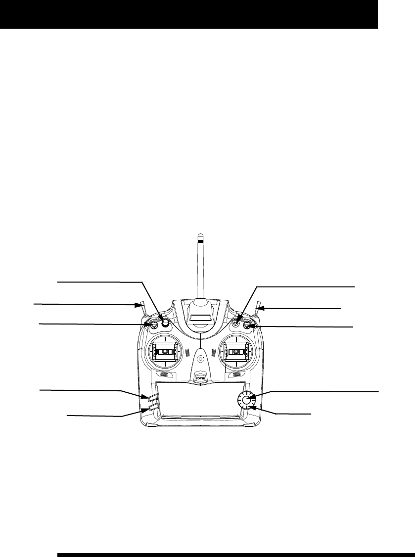
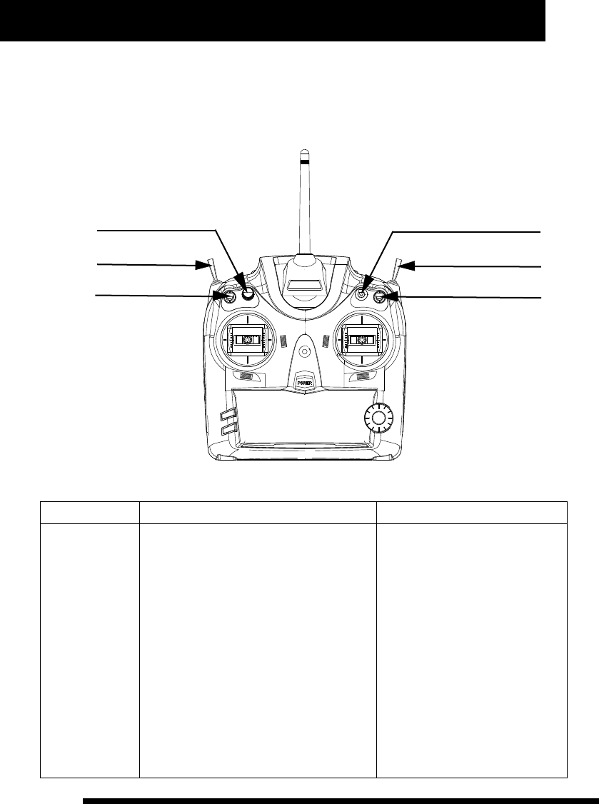
and practical function, the whole external view is illustrated below.
TX technical parameters
1. Battery type: AM3 AA 1.5V 8 cells
2. Working voltage range: 8.5-13V
3. Working current: 200-250mA
4. TX transmitting power: +14dBm
Gyro/ Gear speed
Trainer Switch
D/R Switch
(C) Confirm/ Enter into next step
(D) Adjust
SW(C)
SW(E)
SW(D)
Hov.T/Trim.Flap
3D / Gear
Throttle Hold/ Flap
(A) Enter/ Recover to default
(B) Return
SW(A)
SW(B)
VR(A)
Note: All the switchs and knob function differently in different model type, the function description before “/” is
for helicopter while that after “/” is for airplane.
For fur ther convenient operation, we replace the four general buttons by A, B, C and D thereinafter, and the
corresponding relationship is as follows:
2
www.NineEagle.com
Operation and Instruction of 6-channel TX
X6
A Enter/ Recover to default the button “A” is to enter into menu, and to recover to default in value
adjustment
setup.
B Return the button “B” is to return to menu.
C Confirm/Enter into next step the button “C” is to save current setting values and enter into next step.
D Adjust the button “D” is to choose or adjust values.
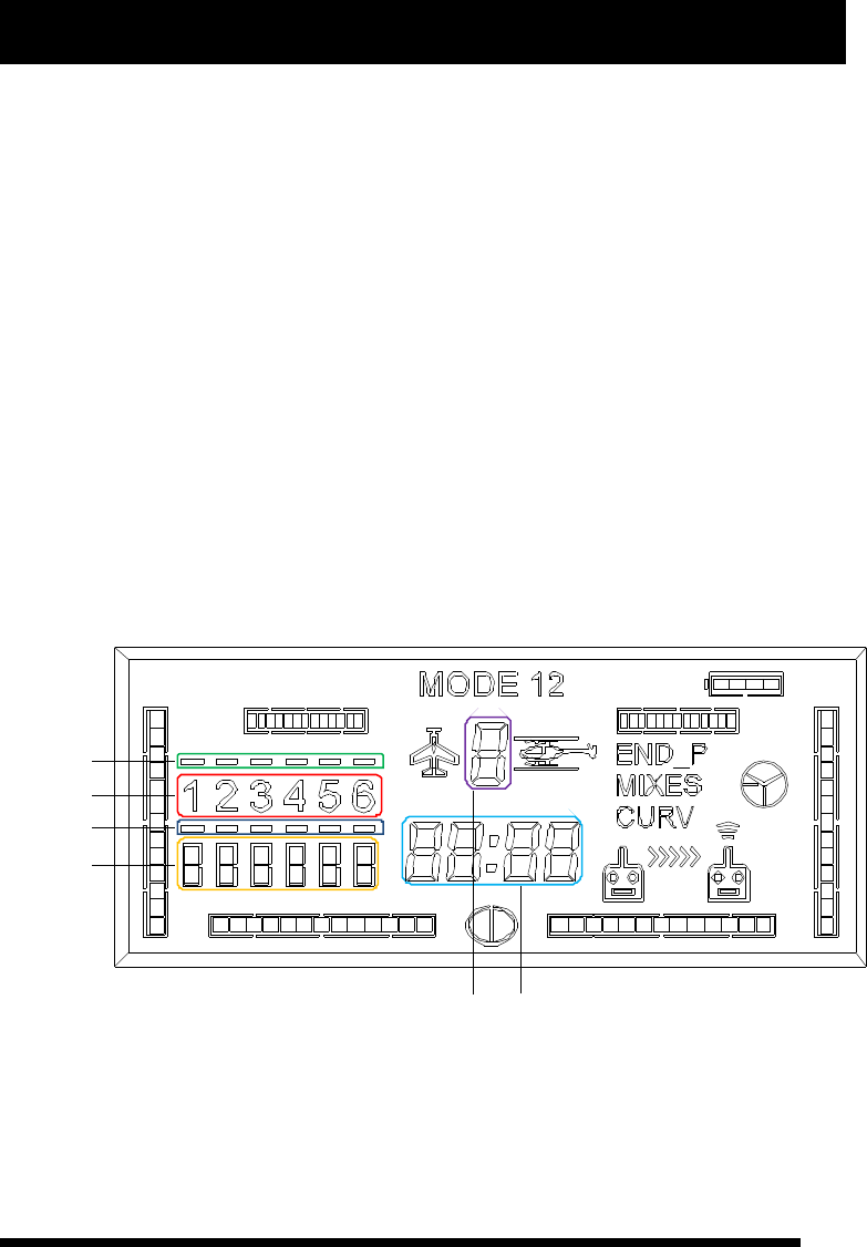
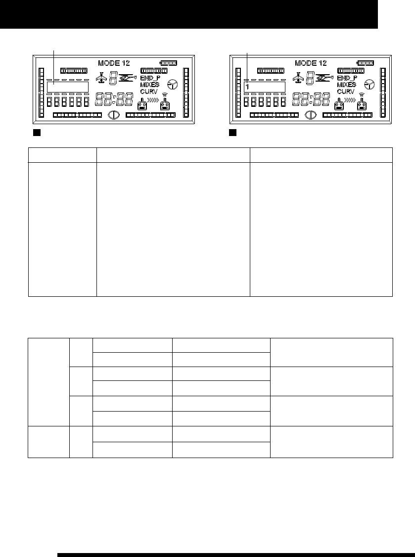
The TX employs high resolution and subsection LCD screen as user interface. All the parameters setup can be
completed according to the above illustration. The whole menu is with layered structure, distinct levels and
easy operation. The LCD display screen is divided into the following par ts according to the menu design
structure.
a : main channel mix identifier
b: channel identifier
c: sub-channel mix identifier
d: channel reversed setting identifier
e: model number identifier
f: value and time display
For fur ther convenient operation, we replace the six identifiers by a, b, c, d, e, and f thereinafter.
The corresponding location is illustrated below:
a
b
c
d
ef
“END-P” represents Rudder Dual Rate parameter, and it will flash when sets the parameter while go solid if the
parameter is not default in stand by status.
“MIXES” represents mix identifier, it will flash when sets it while go solid if there is mix-control activate in stand
by status.

3
www.NineEagle.com
Operation and Instruction of 6-channel TX
X6
“CURV” represents operation curve of control stick, it will flash when sets it while go solid if the curve is not
default in stand by status.
The four surrounding indicating bar of LCD displays current trim position when control stick is not pushing
(throttle channel generally indicates current channel volume), while displays control volume when control stick
is pushing.
Value and time display area (circle in blue) is multipurpose: (1) it displays current throttle volume when timer is
off and in stand by status; (2) it displays each channel's trim value when adjusting each channel; (3) it displays
current time when timer is on.
In stand by status the circle in red “channel identifier” displays ON/OFF status of wing-mix . And it displays
each channel's position or curve dot position when users enter into menu adjustment. “1” represents aileron
channel, “2” represents elevator channel, “3” represents throttle channel, “4” represents rudder channel, “5”
represents landing gear/ sensitivity channel, “6” represents PITCH/Flap channel.
TX stand by status
Place each function switch in normal position (Push each switch towards back cover's direction), and turn on
power to enter into stand by status, and then LCD displays current flight parameters and corresponding
operation information.
There are three kinds of setting parameters for the TX: general parameter setup, advanced parameter setup, and
special function setup. The details are illustrated below:
Press A one second to enter into general parameter setup when TX is in stand by status.
Press A and B one second together to enter into advanced parameter setup when TX is in stand by status.
Airplane and Glider
Function page
General parameter
Channel Reverse Function
Dual Rate Set
General Wing-mix ( △ type, V type, flap/aileron type)
Operation curve and throttle curve setup
Gear speed
Memory trim
Timer
Advanced
parameter
Model number
Model type
User-defined mix
Transmitting power
Wireless Trainner
Wireless copy
Internal data copy
P7
P8
P8
P11
P13
P14
P14
P5
P6
P6
P28
P28
P30
P30

4
www.NineEagle.com
Operation and Instruction of 6-channel TX
X6
Helicopter
Function page
General parameter
Channel Reverse Function
Dual Rate Set
CCPM mix setup
General wing-mix (ATS. Mix)
Operation curve and throttle curve setup
Gyro sensitivity setup
Throttle hold function
Advanced
parameter
Memory trim
Timer
Model number
Model type
Swashplate type
User-defined mix
Transmitting power
P18
Wireless Trainner
Wireless copy
Internal date copy
Special Function
Function page
3D switch safety protection
Throttle hold switch safety protection
Quick zero clearing and reset of timer
Quick switchover of operation mode
Power saving management
Communication protocol choice
Control stick correction
All parameters recover to default
Wire Trainner function
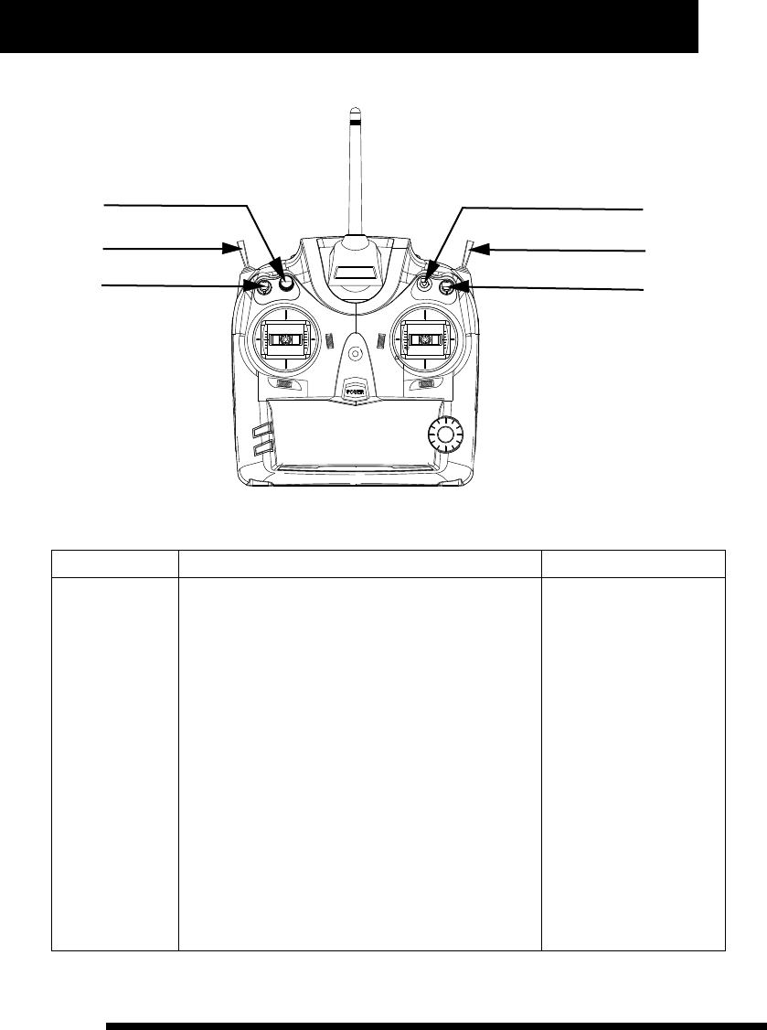
Airplane Operation Instruction
There are several setting parameters for airplane:Model number, Model type, Channel reserve, Dual Rate Set,
Wing-mix, Operation curve, Memory trim, Flight timer, User-defined mix and so on. Each switch position is
illustrated below:
P19
P19
P20
P22
P25
P27
P26
P27
P15
P16
P16
P17
P28
P28
P30
P30
P31
P31
P31
P32
P32
P33
P33
P33
P28
5
www.NineEagle.com
Operation and Instruction of 6-channel TX
X6
Gear speed
Trainer switch
D/R Switch
SW(C)
SW(E)
SW(D)
Flap
Gear
Flap
VR(A)
SW(B)
SW(A)
Model number setup
Function Description Operation Steps Instruction
It can be changed
from 0 to 9.
1、Place TX in stand by status.
2、Press A and B one second together, and “MODE” and
model number identifier (“e”) will flash meanwhile.
3、Press A or C, and “MODE” will go solid while model
number identifier (“e”) flash.
4、Turn D to choose current model number.
5、Press C to save it and then enter into model type
setup automatically.
6、Press B to exit after finishing setup.
Model type will change with
corresponding setting
values of the selected model
number in real time.
It is required to press C to
save value when changing
model number. And model
type will change with model
number for user's
convenient search.
Alteration of model number
will affect the whole setting
parameters, so we suggest
that deal with this
configuration item
according to current
controlled model, and make
sure the model is power off
to avoid sudden movement
of it.

6
www.NineEagle.com
Operation and Instruction of 6-channel TX
X6
Model type setup
Function Description Operation Steps Instruction
It offers two options:
Airplane and
Helicopter.
1、Place TX in stand by status.
2、Press A and B one second together, and “MODE” and
model number identifier (“e”) will flash meanwhile.
3、Turn D until “MODE” and model type identifier flash
meanwhile.
4、Press A or C, “MODE” will go solid while model type
identifier flash.
5、Turn D to choose current model type.
6、Press C to change current model type to selected one,
and recover corresponding parameters to default, and then
enter into user-defined mix setup.
7、Press B to exit after finishing setup.
Model type includes two
options: for helicopter
and for airplane.
Alteration of Model type
w i l l c h a n g e a l l
parameters of current
model to default. User
should be cautious when
using this function. If
you are uncer tain to
change Model type, you
shouldn't press C to
a v o i d r e p l a c i n g t h e
current parameters by
default.If Model type is
determinately changed,
you'd better to turn on TX
again to make sure the
data is saved.
User-defined mix setup
Function Description Operation Steps Instruction
1、Place TX in stand by status.
2、Press A and B one second together, and “MODE” and
model number identifier (“e”) will flash meanwhile.
3、Turn D until “MIXES” and main/sub channel identifier
(“a”and “c”) flash together.
4、Press A or C, “MIXES” and single channel identifier
(“a”or “c”) will flash meanwhile.
5、Turn D to choose the main channel or sub channel to be
set up.
6、 Press A or C, “MIXES” and single channel identifier
(“a”or “c”) will flash meanwhile.(if this mix parameter has
been set up before, “MIXES” and that channel identifier will
flash meanwhile)
7、 Turn D to choose channel number to be set up.
8、Press A or C, “MIXES”, single channel identifier (“a”or
“c”) and time display identifier (“f”) will flash meanwhile.
If the wh ole channel
identifier (“a” and “c”)
f l a s h t og e t h e r w h e n
c h o o s i n g c h a n n e l
position, that means it is
not sel e cted. And if
neither main channel nor
sub channel position is
selected, pressing A or C
will not enter into next
operation with the cursor
moving between “a” and
“c”, and time display
identifier (“f”) displays
cur rent cor responding
mix control volume.
U s e c o r r e s p o n d i n g
control stick of each
c h a n n e l t o c h a n g e
parameter of left/right or
up/down par ts in user-
defiend mix setup.
It provides a group
of free mix control
modes to meet
users' different
needs. And it can
also be set up for
up/down, left/right
asymmetric mix
control mode, one-
way mix and two-
way mix control
mode.

7
www.NineEagle.com
Operation and Instruction of 6-channel TX
X6
Function Description Operation Steps Instruction
9、Turn D to set user-defined mix value, set
left/right or up/down par ts parameter according to
corresponding control stick's switchover. (Press A
one second if you want to recover it to default.)
10、Press C, “MIXES”, another single channel
identifier (“a”or “c”), time display identifier (“f”) will
flash meanwhile. (if this mix parameter has been set
up before, “MIXES” and that channel identifier will
flash meanwhile)
11、Turn D to choose channel number to be set up.
12、Press A or C, “MIXES”, single channel identifier
(“a”or “c”) and time display identifier (“f”) will flash
meanwhile.
13、Turn D to set user-defined mix value, set
left/right or up/down par ts parameter according to
corresponding control stick's switchover. (Press A
one second if you want to recover it to default.)
14、Press C to save data and enter into another
search.
15、Press B to exit after finishing setup.
C o r r e s p o n d i n g c h a n n e l
p a r a m e t e r o f l e f t / r i g h t o r
up/down par t s is r estored
sync h roni z ation whe n A is
pressing. (Namely restore them
to default at the same time).
U s e r - d e f i n e d m i x w i l l b e
com ple ted o nly w ith i ntac t
setting parameter, which means
if either main channel or sub
channel is not set mix parameter,
u s e - d e f i n e d m i x w i l l b e
cancelled.
One-way mix mode is that only
one channel will change with the
other channel's movement. Two-
way mix mode is that both
channels will change each other
with the other's movement.
Asymmetric mix mode is that
both channels can mix control in
left/right or up/down par ts.
U s e r - d e f i n e d m i x s e t t i n g
parameters rang from -100% to
100%.
W h e n “ M I X E S ” a nd si n g le
channel identifier flash together,
press C to cancel the setting
value or to exit this setup.
Channel reverse function
Function Description Operation Steps Instruction
1、Place TX in stand by status.
2、Press A one second and channel reversed setting
identifier (“d”) will flash.
3、Press A or C, sigle channel reverse identifier will
flash.
4、Turn D to choose the channel to be set up.
5、Press A or C, single channel reverse identifier will
flash.
6、Turn D to choose “NOR” or “REV”.
7、Press C to save current channel reverse status
and enter into next channel reverse setup.
8、Press B to exit after finishing setup.
When setting Channel reverse,
the data just reflects current
setting status, not to save it.
You have to press C to save
data.
When choosing “NOR” o r
“REV” for each channel, the TX
outp u t sig n a l r e flect s the
current setting status in real
time. So you must be careful
when choosing “NOR” or “REV”
for throttle channel. And we
suggest users not install the
main motor or propeller to
prevent the damage caused by
propeller sudden rotation.
Make sure the
channel is set up
in right position
to meet operation
requirement
according to the
installation
position of servo.

8
www.NineEagle.com
Operation and Instruction of 6-channel TX
X6
Dual Rate setup:
Function Description Operation Steps Instruction
1、Place TX in stand by status.
2、Press A one second and channel reversed setting
identifier (“d”) will flash.
3、Turn D until “END-P” and channel identifier
“123456” flash meanwhile.
4、Press A or C, “END-P” and single channel
identifier will flash meanwhile.
5、Turn D to choose the channel to be set up.
6、Press A or C, “END-P”, current channel identifier
and time display identifier (“f”) will flash meanwhile.
7、Turn D to set the rudder value, use D/R switch to
choose high-rate mode or low-rate mode, shake the
corresponding channel control stick to select rudder
value for left, right, upper and under sides. (Press A
one second if you want to change Dual Rate Rudder
value of left/right or up/down to default.)
8、Press C to save data and enter into next search.
9、Press B to exit after finishing setup.
When choosing channel, the
time display identifier (“f”) will
display the parameter value of
Dual Rate rudder of the current
channel.
In Rudder Dual Rate value setup
mode, each channel has four
setting parameters which can
be changed through D/R switch
and each channel's
corresponding control stick.
The same channel's left and
right or upper and lower par t
parameter is restored
synchronization when A is
pressing. (Namely restore them
to default at the same time).
D/R value ranges from -125% to
125%.
Note: Negative value indicates
that control direction is
opposite to the swing direction
of control stick.
When choosing
high-rate or low-
rate mode for “AIL”,
“ELE”, “THR” three
channels, you can
set two values for
the control stick's
both sides
(left/right and
up/down)
separately to meet
the servo trim or
operation feeling
adjustment.
Wing-mix parameter setup:
Function Description Operation Steps Instruction
1、Place TX in stand by status.
2、Press A one second and channel reversed setting
identifier (“d”) will flash.
3、Turn D until “MIXES” and channel identifier
“123456” flash together.
4、Press A or C, and “MIXES” flashes while
“123456” disappears. (if this parameter has been set
before, it will display last wing type)
5、Turn D to choose wing-mix type.
6、Press A or C, “MIXES”, current mix mode and
single channel identifier will flash meanwhile.
7、Turn D to choose main channel or sub channel.
“ ” represents no wing-mix.
(shown as picture A below)
“1” represents △type wing-mix.
(shown as picture B below)
“2” represents V type wing-mix.
“3” represents Flap/Aileron wing-
mix.
When choosing channel, time
display identifier (“f”) displays
current channel's wing-mix
parameter value for users'
convenient search.
It provides three
kinds of general
wing-mix
parameters setup
and asymmetric
value setup of
lefe/right or
up/down side of
control stick for
airplane. While
provides ATS. Mix
9
www.NineEagle.com
Operation and Instruction of 6-channel TX
X6
Function Description Operation Steps Instruction
8、Press A or C, “MIXES”, current mix
mode, current mix channel identifier and
time display identifier (“f ”) will flash
meanwhile.
9、Turn D to set wing-mix value, use
corresponding control stick to change
parameter of left/right or up/down par ts.
(Press A one second to recover it to default.)
10、Press C to save data and enter into next
search.
11、Press B to exit afer finishing setup.
Use corresponding control stick of each
channel to change parameter of left/right
or up/down parts in wing-mix setup.
Corresponding channel parameter of
left/right or up/down par ts is restored
synchronization when A is pressing.
(Namely restore them to default at the
same time).
When “MIXES” is flashing and “123456”
is disappered, press C to cancel the
setting value of wing-mix.
Wing-mix setting parameter ranges from -100% to 100%. Negative value represents that control direction is
opposite to the direction of control stick. Wing-mix setup changes with different model type, and the difference
is illustrated below:
Airplane
1
2
3
A mix-control block
B mix-control block
A mix-control block
B mix-control block
A mix-control block
B mix-control block
Aileron channel
Elevator channel
Elevator channel
Rudder channel
Aileron channel
Flap channel
for △shape wing model
for V shape wing model
for Flap/Aileron wing model
Helicopter 1A mix-control block
B mix-control block
Throttle channel
Rudder channel
for ATS Mix of helicopter
1, 2, 3 in the above form represent mix-control type, you can find them in the channel identifier “123456” in
LCD, A mix-control block is the upper channel identifier (“a”), while B mix-control block is the nether par t (“b”).
You should choose model type before setting up this configuration item. When choosing wing-mix type, none of
1, 2, 3 displays on LCD means wing-mix is not set up. And it only displays current wing-mix type in stand by
status. With TX in stand by status, if channel identifier (“b”) displays nothing, that means no wing-mix is set up;
if one of 1, 2, 3 displays on LCD, that means wing-mix is set up.
No wing mix
pictureA
△type wing-mix
pictureB
Operation and Instruction of 6-channel TX
X6
10
www.NineEagle.com
Operation curve setup:
Function Description Operation Steps Instruction
1、Place TX in stand by status.
2、Press A one second and channel reversed setting
identifier (“d”) will flash.
3、Turn D until “CURV” and channel identifier
“123456” flash meanwhile.
4、Press A or C, “CURV” and current channel
identifier will flash meanwhile.
5、 Turn D to choose operation curve to set up for
each channel.
6、Press A or C, “CURV”, current channel identifier
and the first three figures of time display identifier
(“f”) will flash meanwhile, while the last figure of it
displays “E”.
7、Turn D to set operation curve value ( Press A one
seconds to recover it to default)
8、 Press C to save data and enter into next search.
9、Press B to exit afer finishing setup.
When choosing channel,
time display identifier (“f”)
displays current channel
operation curve value, and
end up with “E”.
Positive value of operation
index curve indicates that
m i d d l e c o n t r o l s u r f ace
changes fast while both
ends change slowly. And the
effect is opposite when the
value is negative.
It provides operation
curve setup and can
improve operation
feeling. And it can also
adjust positive and
negative index curve
for Aileron, Elevator,
Rudder three channels,
and Five subsection
curve for throttle
channel.
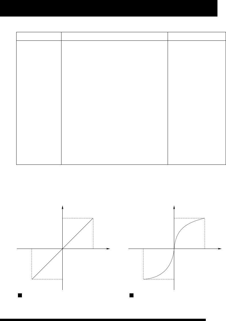
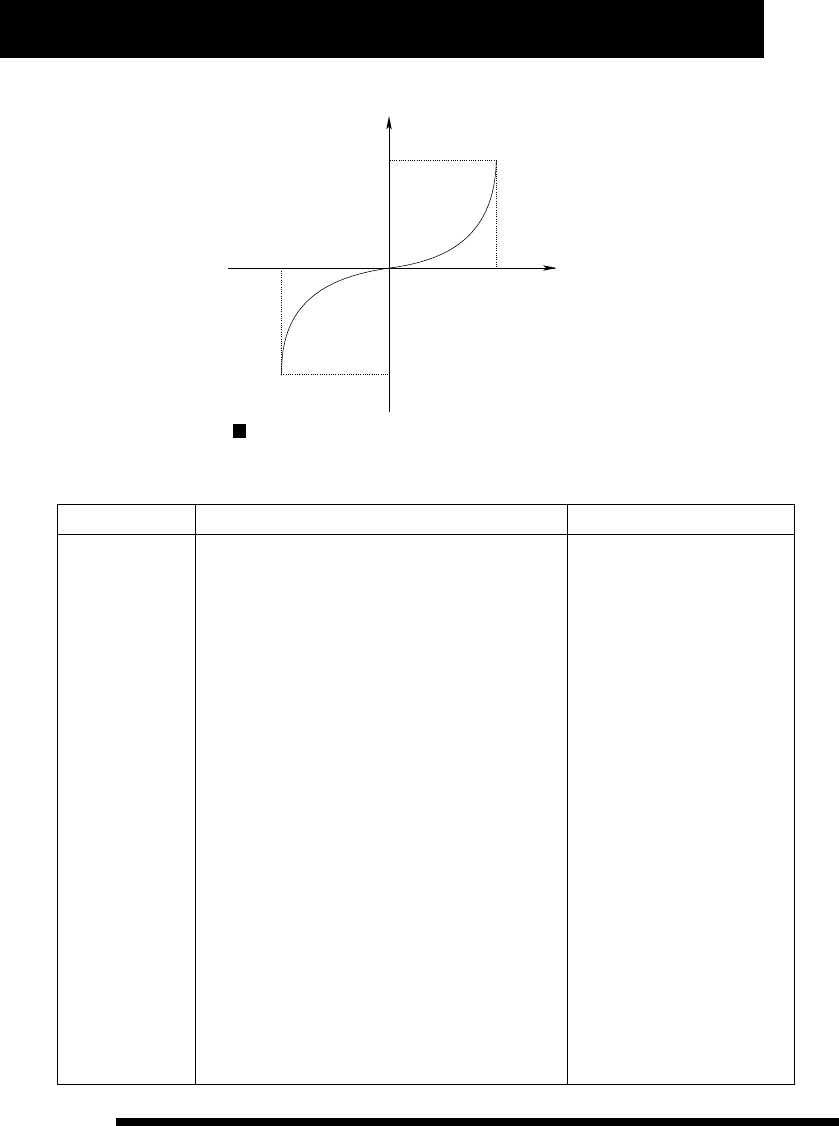
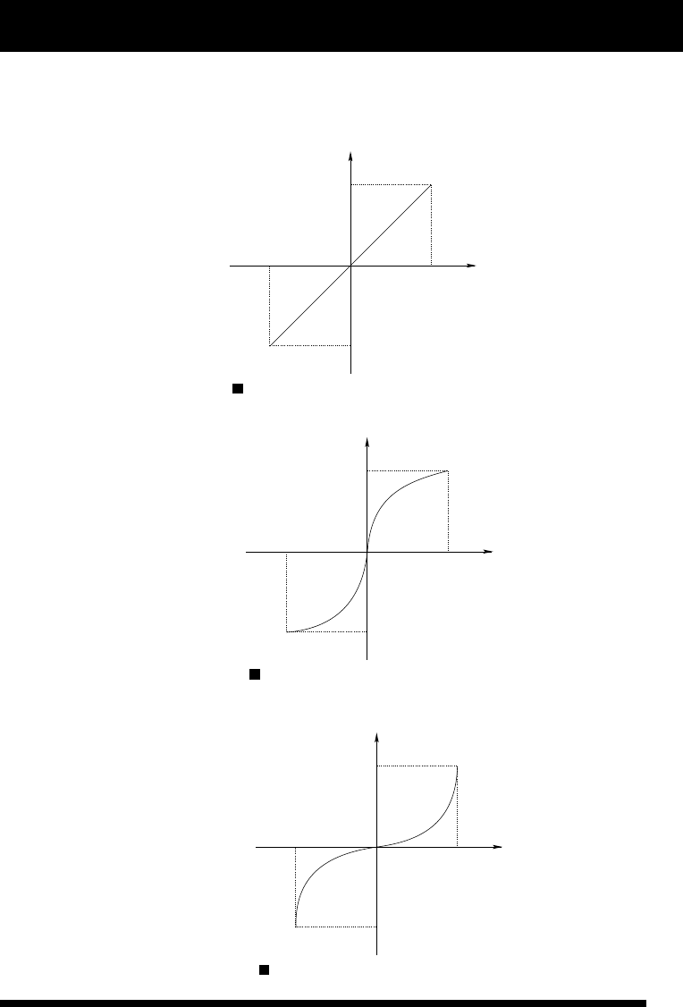
Index curve value ranges from -80% to 80%. The corresponding relationship between index curve and operation
volume output is illustrated below:
operation volume output
swing angle of control stick
index curve value is 0.
operation volume output
swing angle of control stick
index curve value is 60.
11
www.NineEagle.com
Operation and Instruction of 6-channel TX
X6
operation volume output
swing angle of control stick
index curve value is -60.
Five subsection curve setup of throttle channel
Function Description Operation Steps Instruction
1、Place TX in stand by status.
2、Press A one second and channel reversed setting
identifier (“d”) will flash.
3、Turn D until “CURV” and channel identifier
“123456” flash meanwhile.
4、Press A or C, “CURV” and current channel
identifier will flash meanwhile, while the last figure of
time display identifier (“f”) display “E”.
5、Turn D to choose channel, and time display
identifier (“f”) displays “5dot”.
6、Press A or C, “CURV” and current dot identifier
(channel identifier represents dot position) will flash
meanwhile.
7、 Turn D to choose dot position of operation curve.
8、Press A or C, “CURV”, current dot identifier
(channel identifier represents dot position) and the
last three figures of time display identifier (“f”) will
flash meanwhile, while the first figure displays “d”.
9、Turn D to set up current dot position value of
operation curve. (Press A one second to recover
current five dot position values to default).
10、 Press C to save data and enter into next search.
11、Press B to exit after finishing setup.
When cursor moves to “3”, time
display identifier (“f”) display
“ 5 d o t ” , w h i c h m e a n s t h e
channel is 5dot operation curve.
When choosing curve dot, time
display identifier (“f”) displays
current curve dot value, star ting
with “d” for user's convenient
search.
The last figure of time display
identifier (“f ”) displays “E”
when set up parameter value for
operation curve of control stick,
while the first figure of it
dis p lays “d” w h en set up
parameter value for throttle
curve. It is convenient for user
to distinguish.
Setting values of throttle curve
range from 0% to 100%.
It is to set up
operation curve
for throttle.

Operation and Instruction of 6-channel TX
X6
12
www.NineEagle.com
Operation example
Function Description Operation Steps Instruction
1、Place TX in stand by status.
2、Press A one second and channel reversed setting
identifier (“d”) will flash.
3、Turn D until “CURV” and channel identifier
“123456” flash meanwhile.
4、Press A or C, “CURV” and channel identifier “1”
will flash meanwhile.
5、Turn D to choose channel, and make “CURV” and
channel identifier “2” flash meanwhile.
6、Press A or C, “CURV”, channel identifier “2” and
the first three figures of time display identifier (“f”)
will flash meanwhile, while the last figure displays
“E”.
7、Turn D to set up operation curve value as 25.
8、 Press C to save data and enter into next search.
9、Press B to exit after finishing setup.
When choosing channel, time
display identifier (“f”) displays
cur rent channe l operat i o n
curve value, ending up with “E”
for user's convenient search.
Positive value of operation
in dex cur ve ind icates that
m i d d l e c o n t r o l s u r f a c e
changes fast while both ends
change slowly. And the effect is
opposite when the value is
negative.
It is the process of
setting operation
curve of elevator
c h a n n e l a s
p o s i t i v e v a l u e
25%.
The process of setting operation curve of elevator channel as positive value 25% is as follows:
Function Description Operation Steps Instruction
1、Place TX in stand by status.
2、Press A one second and channel reversed setting
identifier (“d”) will flash.
3、Turn D until “CURV” and channel identifier
“123456” flash meanwhile.
4、Press A or C, “CURV” and channel identifier “1”
will flash meanwhile.
5、Turn D to choose channel, and make “CURV” and
channel identifier “3” flash meanwhile, while time
display identifier (“f”) displays “5dot”.
6、Press A or C, “CURV” and channel identifier “1”
will flash meanwhile.
7、Press A or C, “CURV”, channel identifier “1” and
the last three figures of time display identifier (“f”)
will flash meanwhile, while the first figure displays
“d”.
When cursor moves to “3”,
time display identifier (“f”)
display “5dot”, which means
the channel is 5dot operation
curve.
When choosing curve dot, time
display identifier (“f”) displays
c u r r e n t c u r v e do t v a l ue ,
star ting with “d” for user's
convenient search.
The last figure of time display
identifier (“f”) displays “E”
when set up parameter value
for operation curve of control
stick, while the first figure of it
displays “d” when set up
parameter value for throttle
curve. It is convenient for user
to distinguish.
It is the process to
set throttle curve
as 5dot:
The first dot value:
2%.
The second dot
value: 28%.
T h e t h i r d d o t
value: 52%.
T h e f o u r t h d o t
value: 77%.
The fifth dot value:
98%.
The process to set throttle curve as 5dot is as follows:

13
www.NineEagle.com
Operation and Instruction of 6-channel TX
X6
Function Description Operation Steps Instruction
8、Turn D to set up current dot value as 002.
9、Press C, “CURV” and channel identifier “2” will flash meanwhile.
10、Press A or C, “CURV”, channel identifier “2” and the last three
figures of time display identifier (“f”) will flash meanwhile, while the
first figure displays “d”.
11、Turn D to set up current dot value as 028.
12、Press C, “CURV” and channel identifier “3” will flash
meanwhile.
13、Press A or C, “CURV”, channel identifier “3” and the last three
figures of time display identifier (“f”) will flash meanwhile, while the
first figure displays “d”.
14、Turn D to set up current dot value as 052.
15、Press C, “CURV” and channel identifier “4” will flash
meanwhile.
16、Press A or C, “CURV”, channel identifier “4” and the last three
figures of time display identifier (“f”) will flash meanwhile, while the
first figure displays “d”.
17、Turn D to set up current dot value as 077.
18、Press C, “CURV” and channel identifier “5” will flash
meanwhile.
19、Press A or C, “CURV”, channel identifier “5” and the last three
figures of time display identifier (“f”) will flash meanwhile, while the
first figure displays “d”.
20、Turn D to set up current dot value as 098.
21、Press C to save data.
22、Press B to exit after finishing setup.
Function Description Operation Steps Instruction
1、Place TX in stand by status.
2、Press A one second and channel reversed setting identifier (“d”)
will flash.
3、Turn D until time display identifier (“f”) displays “G-S” and
flashes meanwhile.
4、Press A or C, and the three figures identifier will flash.
5、Turn D to adjust current gear speed value ( Press A one second
to recover it to default)
6、 Press C to save data and enter into memory trim setup.
7、Press B to exit afer finishing setup.
Gear speed setup
There are two
rates to choose:
fast rate and slow
rate.
Tu r n g e a r r a t e
adjustment switch
(SW(C)) to choose
fast or slow rate, in
order to set values
separately.
Operation and Instruction of 6-channel TX
X6
14
www.NineEagle.com
Memory trim setup:
Function Description Operation Steps Instruction
1、Place TX in stand by status.
2、Press A one second and channel reversed setting identifier
(“d”) will flash.
3、Turn D until “Aileron, Elevator, Rudder” channel trim circle
flash meanwhile.
4、Press A or C, single channel reverse identifier will flash while
time display identifier (“f”) displays current memory trim value.
5、Turn D to choose channel trim circle.
6、Press A or C, single channel reverse identifier and time display
identifier (“f”) will flash meanwhile.
7、Turn D to adjust current channel memory trim value ( Press A
one second to recover it to default)
8、Press C to save data and enter into next search.
9、Press B to exit afer finishing setup.
When choosing
c h a n n e l , t i m e
display identifier
( “ f ” ) d i s p l a y s
c u r r e n t c h a n ne l
memory trim value
f o r u s e r ' s
convenient search.
Setting values of
memory trim range
f r o m - 1 0 0 % t o
100%.
I t c a n s u p p o r t
“Aileron, Elevator,
R u d d e r ” t h r e e
c h a n n e l s t r i m
adju s t ment, a n d
also correct rudder
d e v i a t i o n w i t h
memory function.
Flight timer setup:
Function Description Operation Steps Instruction
1、Place TX in stand by status.
2、Press A one second and channel
reversed setting identifier (“d”) will
flash.
3、Turn D until time display identifier
(“f”) flashes.
4、Press A or C, the four figures of time
display ident ifier (“f ” ) will f lash
meanwhile.
5、Turn D to set value of flight timer
(Press A one second to set it as 5
minutes.)
6、Press C to save data, star t timer and
enter into channel reverse setup.
7、Press B to exit afer finishing setup.
When adjusting value of flight timer, the
second identifier of time display identifier
(“f”) will not flash, the minimum unit is
minute.
With the timer is power on, press C for a
long time to eliminate current value and
restar t or turn off the timer in stand by
status. (Press C for a long time can shut
it down when the timer is power on, while
star t it when the timer is power off.)
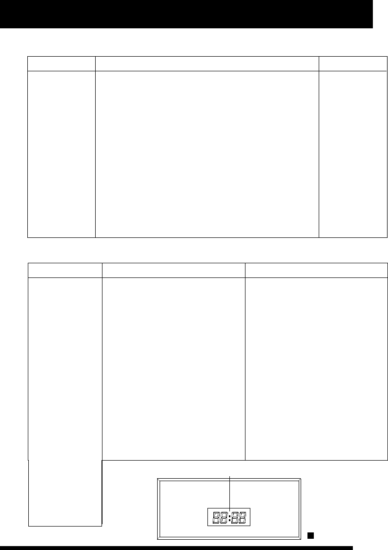
When the setting value is 0, which
means not to star t the timer. According to
the two second dot status of time display
identifier (“f”) to distinguish menu level
when setting this configuration item.
(shown as pictureC below)
The X6 features an
on screen timer,
which is to count
flight time, and it
adopts count down
mode with warning
p r o m p t . W h e n
throttle volume is
more t han 30% ,
timer will star t to
count time, while
p a u s e c o u n t i n g
when it is less than
30%. It changes to
U P - T I M E R
a u t o m a t i c a l l y
w h e n D O W N -
T I M E R i s o v e r.
Timer value rangs
f r o m 1 t o 6 0
minutes.
pictureC
second dot
15
www.NineEagle.com
Operation and Instruction of 6-channel TX
X6
Helicopte Operation Instruction
There are several setting parameters for helicopter:Model number, Model type, Channel reserve, Rudder dual
rate, CCPM mix, Operation curve, Memory trim, Throttle hold, Flight timer, User-defined mix and so on. Each
switch position is illustrated below:
Gyro
Hov.T button
Trainer switch
D/R switch
F.mode switch
Throttle hold
Model number
Function Description Operation Steps Instruction
1、Place TX in stand by status.
2、Press A and B one second together, and
“MODE” and model number identifier (“e”) will
flash meanwhile.
3、Press A or C, and “MODE” will go solid
while model number identifier (“e”) flash.
4、Turn D to choose current model number.
5、Press C to save it and then enter into model
type setup.
6、Press B to exit after finishing setup.
M o d e l t y p e w i l l c h a n g e w i t h
corresponding setting values of the
selected model number in real time.
It is required to press C to save data
when changing model number. Model
type will change with model number
when choosing model number for
user's convenient search.
Alteration of model number will affect
the whole setting parameters, so we
s u g g e s t t h a t d e a l w i t h t h i s
configuration item according to
current controlled model, and make
sure the model is power off to avoid
sudden movement of it.
It can be changed
from 0 to 9.

Operation and Instruction of 6-channel TX
X6
16
www.NineEagle.com
Model type
Function Description Operation Steps Instruction
1、 Place TX in stand by status.
2、Press A and B one second together, and
“MODE” and model number identifier (“e”) will
flash meanwhile.
3、Turn D, “MODE” and model type identifier
will flash meanwhile.
4、Press A or C, “MODE” will go solid while
model type identifier flash.
5、Turn D to choose current model type.
6、Press C to change current model type to
selected one, and recover corresponding
parameters to default, and then enter into
swashplate type setup.
7、Press B to exit after finishing setup.
Model type includes two options:
for helicopter and for airplane.
Alteration of Model type will change
all parameters of current model to
default. User should be cautious
when using this function. If you are
uncer tain to change Model type,
you shouldn't press C to avoid
replacing the current parameters by
d e f a u l t . I f M o d e l t y p e i s
deter min a t e ly change d , y o u 'd
better to turn on TX again to make
sure the data is saved.
Model type
Swashplate type
Function Description Operation Steps Instruction
1、Place TX in stand by status.
2、Press A and B one second together,
“MODE” and model number identifier (“e”) will
flash meanwhile.
3、Turn D , “MODE” and Swashplate type
identifier will flash meanwhile.
4、Press A or C, “MODE” will go solid while
Swashplate type identifier flash.
5、Turn D to choose Swashplate type.
6、Press C to save current Swashplate type
and enter into user-defined mix setup.
7、Press B to exit after finishing setup.
There are two swashplate types to
choose: CCPM90° and CCPM120°.
The X6 offers two
swashplate types:
C C P M 9 0 ° a n d
CCPM120°.
S e l e c t t h e
swashplate type to
m a t c h y o u r
helicopter.
17
www.NineEagle.com
Operation and Instruction of 6-channel TX
X6
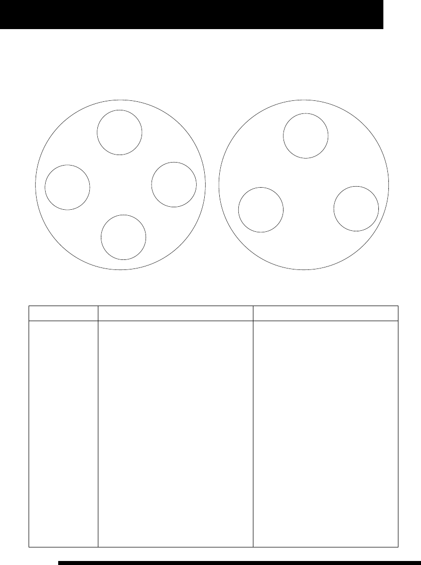
CCPM90° Swashplate drives by two or four servos, while CCPM120° Swashplate drives by three servos. The
installation position is illustrated below:
Swashplate
Elevator
servo
Aileron
servo
PITCH
servo
CCPM90°
Aileron
servo
Elevator
servo
Swashplate
CCPM120°
Aileron
servo
Elevator
servo
User-defined mix
Function Description Operation Steps Instruction
1、Place TX in stand by status.
2、Press A and B one second together, and
“MODE” and model number identifier (“e”)
will flash meanwhile.
3、Turn D until “MIXES” and main/sub
channel identifier (“a” and “c”) flash
together.
4、Press A or C, “MIXES” and single
channel identifier (“a”or “c”) will flash
meanwhile.
5、Turn D to choose main channel or sub
channel.
6、Press A or C, “MIXES” and single
channel identifier (“a”or “c”) will flash
meanwhile.(if this mix parameter has been
set up before, “MIXES” and that channel
identifier will flash meanwhile)
7、Turn D to choose channel number to be
set up.
If the whole channel identifier (“a” and
“c”) flash together when choosing
channel position, that means it is not
selected. And if neither main channel nor
sub cha nnel pos itio n i s s elec ted,
pressing A or C will not enter into next
ope rati on wit h t he cur sor mo v ing
between “a” and “c”, and time display
i d e n t i f i e r ( “ f ” ) d i s p l a y s c u r r e n t
corresponding mix control volume.
Use corresponding control stick of each
channel to change parameter of left/right
or up/down par ts in user-defiend mix
setup.
Corresponding channel parameter of
left/right or up/down par ts is restored
synchronization when A is pressing.
(Namely restore them to the default at the
same time).
It provides a group
of free mix control
m o d e s t o m e e t
u s e rs ' d i f fe r e nt
needs. And it can
also be set up for
up/down, left/right
asym m e tric mix
c o n t r o l m o d e ,
one-way mix and
t w o - w a y m i x
control mode.

Operation and Instruction of 6-channel TX
X6
18
www.NineEagle.com
Function Description Operation Steps Instruction
8、Press A or C, “MIXES”, single channel
identifier (“a”or “c”) and time display identifier
(“f”) will flash meanwhile.
9、Turn D to set user-defined mix value, set
left/right or up/down par ts parameter according to
corresponding control stick's switchover. (Press
A one second if you want to recover it to default.)
10、Press C and “MIXES”, another single
channel, time display identifier(“f”)will flash
meanwhile. (if this mix parameter has been set up
before, “MIXES” and that channel will flash
meanwhile)
11、Turn D to choose channel number to be set
up.
12、Press A or C, “MIXES”, single channel
identifier (“a”or “c”) and time display identifier
(“f”) will flash meanwhile.
13、Turn D to set user-defined mix value, set
left/right or up/down par ts parameter according to
corresponding control stick's switchover. (Press
A one second if you want to recover it to default.)
14、Press C to save data and enter into another
search.
15、Press B to exit after finishing setup.
U s e r- d e f i n e d m i x w i l l b e
completed only with intact
setting parameter, which means
if either main channel or sub
c h a n n e l i s n o t s e t m i x
parameter, use-defined mix will
be cancelled.
One-way mix mode is that only
one channel will change with
the other channel's movement.
Two- way mix mode is that both
channels will change each
o t h e r w i t h t h e o t h e r ' s
movement. Asymmetric mix
mode is that both channels can
mix control in lef t/right or
up/down par ts.
U s e r- d e f i n e d m i x s e t t i n g
parameters rang from -100% to
100%.
Whe n “ M IXES ” a nd sin g le
channel flash together, press C
to cancel the setting value or to
exit this setup.
Channel Reverse Function
Function Description Operation Steps Instruction
When in Channel reverse setting, the
data just reflects current setting
status, not to save it. You have to
press C to save data.
When choosing “NOR” or “REV” for
each channel, the TX output signal
reflects the current setting status in
real time. So you must be careful
when choosing “NOR” or “REV” for
throttle channel. And we suggest
users not install the main motor or
propeller to prevent the damage
caused by propeller sudden rotation.
M a k e s u r e t h e
channel is set up
in right position to
m e e t o p e r a t i o n
r e q u i r e m e n t
according to the
i n s t a l l a t i o n
position of servo.
1、Place TX in stand by status.
2、Press A one second and channel reversed
setting identifier (“d”) will flash.
3、Press A or C and sigle channel reverse
identifier will flash.
4、Turn D to choose the channel to be set up.
5、Press A or C, single channel reverse
identifier will flash.
6、Turn D to choose “NOR” or “REV”.
7、Press C to save current channel reverse
status and enter into next channel reverse
setup.
8、Press B to exit after finishing setup.

19
www.NineEagle.com
Operation and Instruction of 6-channel TX
X6
CCPM Mix setup:
Function Description Operation Steps Instruction
When choosing channel, the
time display identifier (“f”)
will display cur rent mix-
control volume for user's
convenient search.
When setting mix-control
parameter for CCPM120°
swashplate, “1” represents
A i l e r o n c h a n n e l , “ 2 ”
represents Elevator channel,
and “3” represents PITCH
channel.
All the setting parameters are
percentage of each channel,
and it rangs from -100% to
100%.
It is to set
CCPM120°
swashplate mix
parameter for
helicopter.
CCPM90° has no
this configuration
item for helicopter
and airplane.
1、Place TX in stand by status.
2、Press A one second and channel reversed setting
identifier (“d”) will flash.
3、Turn D until “END-P” and channel identifier
“123456” flash meanwhile.
4、Press A or C, swashplate type and single channel
identifier will flash meanwhile.
5、Turn D to choose channel for CCPM120° mix-
control.
6、Press A or C, swashplate type, single channel
identifier and time display identifier (“f”) will flash
meanwhile.
7、Turn D to adjust current channel mix-control
volume (press A one second to recover it to default.)
8、Press C to save data and enter into another search.
9、Press B to exit after finishing setup.
Dual Rate Setup:
Function Description Operation Steps Instruction
When choosing channel, the
time display identifier (“f”) will
display the parameter value of
Dual Rate rudder of the current
channel.
In Dual Rate value setup
mode, each channel has four
setting parameters which can
b e ch a n g e d t h r o ug h D/ R
switch and each channel's
corresponding control stick.
The same channel's left and
right or upper and lower par t
p a r a m e t e r i s r e s t o r e d
synchronization when A is
pr essing. ( Namel y re store
them to default at the same
time).
W h e n c h o o s i n g
high-rate or low-
rate mode for “AIL”,
“ELE”, “THR” three
channels, you can
set two values for
the control stick's
b o t h s i d e s
( l e f t / r i g h t a n d
u p / d o w n )
separately to meet
the servo trim or
op eration fee ling
adjustment.
1、Place TX in stand by status.
2、Press A one second and channel reversed
setting identifier (“d”) will flash.
3、Turn D until “END-P” and channel identifier
“123456” flash meanwhile.
4、Press A or C, “END-P” and single channel
identifier will flash meanwhile.
5、Turn D to choose the channel to be set up.
6、Press A or C, “END-P”, current channel
identifier and time display identifier (“f”) will flash
meanwhile.

Operation and Instruction of 6-channel TX
X6
20
www.NineEagle.com
Function Description Operation Steps Instruction
7、Turn D to set the rudder value, use D/R switch
to choose high-rate mode or low-rate mode, shake
the corresponding channel control stick to select
rudder value for left, right, upper and under sides.
(Press A one second if you want to change Dual Rate
Rudder value of left/right or up/down to default.)
8、Press C to save data and enter into next search.
9、Press B to exit after finishing setup.
D/R value ranges from -125% to
125%。
Note: Negative value indicates
that control direction is opposite
to the swing direction of control
stick.
Wing-mix parameter setup:
Function Description Operation Steps Instruction
1、Place TX in stand by status.
2、Press A one second and channel reversed
setting identifier (“d”) will flash.
3、Turn D until “MIXES” and channel identifier
“123456” flash together.
4、Press A or C, and “MIXES” will flash while
“123456” disappear. (if this parameter has been set
before, it will display last wing type)
5、Turn D to choose wing-mix type.
6、Press A or C, “MIXES”, current mix mode and
single channel will flash meanwhile.
7、Turn D to choose main channel or sub channel.
8、Press A or C, “MIXES”, current mix mode,
current mix block sector and time display identifier
(“f”) will flash meanwhile.
9、Turn D to set win g -mix valu e , u se
corresponding control stick to change parameter of
left/right or up/down par ts. (Press A one second to
recover it to default.)
10、Press C to save data and enter into next
search.
11、Press B to exit afer finishing setup.
“ ” represents no wing-mix
“1” represents ATS. Mix.
(the same with page 9 picture
A.B)
When choosing channel, time
display identifier (“f”) displays
c u r r e n t c h a nn e l ' s w i n g - m ix
p a r a m e t e r v a l u e f o r u s e r s '
convenient search.
Use corresponding control stick
of e a c h channel t o change
parameter of left/right or up/down
par ts in wing-mix setup.
Corresponding channel parameter
of left/right or up/down par ts is
restored synchronization when A
is pressing. (Namely restore them
to the default at the same time).
When “MIXES” is flashing and
“123456” is disappered, press C
to cancel the setting value of
wing-mix.
It provides three
kinds of general
w i n g - m i x
parameters setup
and asymmetric
v a lu e s e t u p o f
l e f e / r i g h t o r
up/down side of
control stick for
a i r p la n e . W h i le
provides ATS. Mix
for helicopter.

21
www.NineEagle.com
Operation and Instruction of 6-channel TX
X6
Wing-mix setting parameter range is from -100% to 100%. Negative value represents that control direction is
opposite to the direction of control stick. Wing-mix setup changes according to different model type, as
illustration below:
Airplane
1
2
3
A mix-control block
B mix-control block
A mix-control block
B mix-control block
A mix-control block
B mix-control block
Aileron channel
Elevator channel
Elevator channel
Rudder channel
Aileron channel
Flap channel
for △shape wing model
for V shape wing model
for Flap/Aileron wing model
Helicopter 1A mix-control block
B mix-control block
Throttle channel
Rudder channel
for ATS Mix of helicopter
1, 2, 3 in the above form represent mix-control type, you can find them in the channel identifier “123456” in
LCD, A mix-control block is the upper channel identifier (“a”), while B mix-control block is the nether par t (“b”).
You should choose model type before setting up this configuration item. When choosing wing-mix type, none of
1, 2, 3 displays on LCD means wing-mix is not set up. And it only displays current wing-mix type in stand by
status. With TX in stand by status, if channel identifier (“b”) displays nothing, that means no wing-mix is set up;
if one of 1, 2, 3 displays on LCD, that means wing-mix is set up.
Operation curve setup
Function Description Operation Steps Instruction
1、Place TX in stand by status.
2、Press A one second and channel reversed setting
identifier (“d”) will flash.
3、Turn D until “CURV” and channel identifier “123456”
flash meanwhile.
4、Press A or C, “CURV” and current channel identifier will
flash meanwhile.
5、Turn D to choose operation curve to set up each channel.
6、Press A or C, “CURV”, current channel identifier and the
first three figures of time display identifier (“f”) will flash
meanwhile, while the last figure of it displays “E”.
7、Turn D to set operation curve value ( Press A one second
to recover it to default)
8、Press C to save data and enter into next search.
9、Press B to exit afer finishing setup.
W h e n c h o o s i n g
channel, time display
identifier (“f”) displays
c u r r e n t c h a n n e l
operation curve value,
and end up with “E”.
P o s i t i v e v a l u e o f
operation index curve
indicates that middle
c o n t r o l s u r f a c e
cha n ges fas t w hile
b o t h e n d s c h a n g e
slowly. And the effect
is opposite when the
value is negative.
I t p r o v i d e s
ope rat ion cu r ve
s e t u p a n d c a n
improve operation
feeling. And it can
a l s o a d j u s t
p o s i t i v e a n d
n e g a t i v e i n d e x
curve for Aileron,
Elevator, Rudder
three chann e l s ,
a n d F i v e
subsection curve
f o r T h r o t t l e
channel.
Operation and Instruction of 6-channel TX
X6
22
www.NineEagle.com
Index curve value ranges from -80% to 80%. The corresponding relationship between index curve and operation
volume output is illustrated below:
operation volume output
swing angle of control stick
index curve value is 0.
operation volume output
swing angle of control stick
index curve value is 60.
operation volume output
swing angle of control stick
index curve value is -60.

23
www.NineEagle.com
Operation and Instruction of 6-channel TX
X6
Five subsection curve setup of throttle and PITCH channel
Function Description Operation Steps Instruction
1、Place TX in stand by status.
2、Press A one second and channel reversed setting
identifier (“d”) will flash.
3、Turn D until “CURV” and channel identifier
“123456” flash meanwhile.
4、Press A or C, “CURV” and current channel identifier
will flash meanwhile, while the last figure of time display
identifier (“f”) display “E”.
5、Turn D to choose channel, and time display
identifier (“f”) displays “5dot”.
6、Press A or C, “CURV” and current dot identifier
(channel identifier represents dot position) will flash
meanwhile.
7、Turn D to choose dot position of operation curve.
8、Press A or C, “CURV”, current dot identifier
(channel identifier represents dot position) and the last
three figures of time display identifier (“f”) will flash
meanwhile, while the first figure displays “d”.
9、Turn D to set up current dot position value of
operation curve. (Press A one second to recover current
five dot position values to default).
10、Press C to save data and enter into next search.
11、Press B to exit after finishing setup.
When cursor moves to
“3”, time display identifier
( “ f ” ) d i s p l a y “ 5 d o t ” ,
which means the channel
is 5dot operation curve.
When choosing curve dot,
ti me d ispla y id entif ier
(“f ”) dis pla ys cur r ent
curve dot values, star ting
w i t h “ d ” f o r u s e r ' s
convenient search.
The last figure of time
display identifier (“f ”)
displays “E” when set up
p a r a m e t e r v a l u e f o r
operation curve of control
stick, while the first figure
of it displays “d” when set
up parameter value for
t h r o t t l e c u r v e . I t i s
convenient for user to
distinguish.
Setting values of throttle
curve range from 0% to
100%.
It is process of
Five subsection
cur ve setup for
throttle and PITCH
channel.
Operation example
The process of setting operation curve of elevator channel as positive value 25% is as follows:
Function Description Operation Steps Instruction
When choosing channel, time display
identifier (“f ”) displays c ur rent
chann el o peration cu r ve va lue ,
end ing up wit h “ E” for u s er' s
convenient search.
Positive value of operation index
curve indicates that middle control
sur face changes fast while both ends
change slowly. And the effect is
opposite when the value is negative.
It is the process of
se tting ope ration
curve of elevator
channel as positive
value 25%.
1、Place TX in stand by status.
2、Press A one second and channel reversed
setting identifier (“d”) will flash.
3、Turn D until “CURV” and channel identifier
“123456” flash meanwhile.
4、Press A or C, “CURV” and channel identifier
“1” will flash meanwhile.
5、Turn D to choose channel, and make
“CURV” and channel identifier “2” flash
meanwhile.

24
www.NineEagle.com
Operation and Instruction of 6-channel TX
X6
Function Description Operation Steps Instruction
6、Press A or C, “CURV”, channel identifier “2” and the first
three figures of time display identifier (“f”) will flash
meanwhile, while the last figure displays “E”.
7、Turn D to set up operation curve value as 25.
8、Press C to save data and enter into next search.
9、Press B to exit after finishing setup.
The setup of normal PITCH curve and 3D curve is different. Throttle hold switch must be on when sets 3D PITCH
curve. The process of 3D PITCH curve setup is as follows:
The first dot value: 30%
The second dot value: 35%
The third dot value: 40%
The four th dot value: 45%
The fifth dot value: 52%
Place throttle hold switch in on status, and then operate as follows:
Function Description Operation Steps Instruction
When cursor moves to “6”, time
display identifier (“ f ” ) dis pla y
“5dot”, which means the channel is
5dot operation curve.
When choosing curve dot, time
display identifier (“f”) displays
current curve dot values, star ting
with “d” for user's convenient
search.
The last figure of time display
identifier (“f”) displays “E” when set
up parameter value for operation
curve of control stick, while the first
figure of it displays “d” when set up
parameter value for throttle curve. It
is convenient for user to distinguish.
It is the process of
setting operation
c u r v e v a l ue of
elevator channel
as 25%.
1、Place TX in stand by status.
2、Press A one second and channel reversed
setting identifier (“d”) will flash.
3、Turn D until “CURV” and channel identifier
“123456” flash meanwhile.
4、Press A or C, “CURV” and channel identifier
“1” will flash meanwhile.
5、Turn D to choose PITCH channel, “CURV”
and channel identifier “6” flash meanwhile,
while time display identifier (“f”) displays
“5dot”.
6、Press A or C, “CURV” and channel identifier
“1” will flash meanwhile.
7、Press A or C, “CURV”, channel identifier “1”
and the last three figures of time display
identifier (“f”) will flash meanwhile, while the
first figure displays “d”.
8、Turn D to set up current dot value as 030.
9、Press C, “CURV” and channel identifier “2”
will flash meanwhile.
25
www.NineEagle.com
Operation and Instruction of 6-channel TX
X6
Function Description Operation Steps Instruction
10、Press A or C, “CURV”, channel identifier “2” and the last three
figures of time display identifier (“f”) will flash meanwhile, while the
first figure displays “d”.
11、Turn D to set up current dot value as 035.
12、Press C, “CURV” and channel identifier “3” will flash meanwhile.
13、Press A or C, “CURV”, channel identifier “3” and the last three
figures of time display identifier (“f”) will flash meanwhile, while the
first figure displays “d”.
14、Turn D to set up current dot value as 040.
15、Press C, “CURV” and channel identifier “4” will flash meanwhile.
16、Press A or C, “CURV”, channel identifier “4” and the last three
figures of time display identifier (“f”) will flash meanwhile, while the
first figure displays “d”.
17、Turn D to set up current dot value as 045.
18、Press C, “CURV” and channel identifier “5” will flash meanwhile.
19、Press A or C, “CURV”, channel identifier “5” and the last three
figures of time display identifier (“f”) will flash meanwhile, while the
first figure displays “d”.
20、Turn D to set up current dot value as 052.
21、Press C to save data.
22、Press B twice to exit after finishing setup.
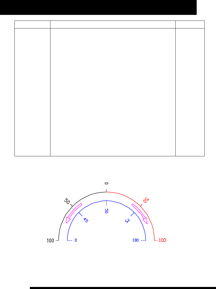
Gyro sensitivity setup:
Sensitivity values and Gyro status are illustrated below:
As illustration, the figures in blue are setting values and the figures in red and black are corresponding sensitivity
values. The red par t represents Lock Tail sensitivity while the black par t represents Non-lock sensitivity.

26
www.NineEagle.com
Operation and Instruction of 6-channel TX
X6
Function Description Operation Steps Instruction
1、Place TX in stand by status.
2、Press A one second and channel reversed setting
identifier (“d”) will flash.
3、Turn D until time display identifier (“f”) displays “G-S”
and flash.
4、Press A or C and the “three figures” will flash.
5、Press D to adjust the current sensitivity value. (Press A
to restore it to default.)
6、Press C to save data and enter into Memory trim setup.
7、Press B to exit after finishing setup.
Press the Flap/Gyro
button to choose Lock
Tai/Non-lock Tail type,
so as to set the value
separately.
T h i s f u n c t i o n
suppor ts the user
to set sensitivity
value of gyro.
Memory trim setup:
Function Description Operation Steps Instruction
1、Place TX in stand by status.
2、Press A one second and channel reversed setting
identifier (“d”) will flash.
3、Turn D until “Aileron, Elevator, Rudder” channel trim
circle flash meanwhile.
4、Press A or C, single channel reverse identifier will flash
while time display identifier (“f”) displays current memory
trim value.
5、Turn D to choose channel trim circle.
6、Press A or C, single channel reverse identifier and time
display identifier (“f”) will flash meanwhile.
7、Turn D to adjust current channel memory trim value (
Press A one second to recover it to default)
8、Press C to save data and enter into next search.
9、Press B to exit afer finishing setup.
W h e n c h o o s i n g
channel, time display
identifier (“f”) displays
c u r r e n t c h a n n e l
memory trim value for
u s e r ' s c o n v e n i e n t
search.
S e t t i n g v a l u e s o f
m e m o r y t r i m r a n g e
from -100% to 100%.
I t c a n s u p p o r t
“Aileron, Elevator,
R u d d e r ” t h r e e
c h a n n e l s t r i m
adjustme nt, an d
a l s o c o r r e c t
r udder d eviation
w i t h m e m o r y
function.

27
www.NineEagle.com
Operation and Instruction of 6-channel TX
X6
Throttle hold setup:
Function Description Operation Steps Instruction
1、Place TX in stand by status.
2、Press A one second and channel reversed setting
identifier (“d”) will flash.
3、Turn D until time display identifier (“f”) flashes, and the
last three figures display current throttle hold value, while the
first figure display “H”.
4、Press A or C, the last three figures of time display
identifier (“f”) display throttle hold value and flash, while the
first figure diplays “H”.
5、Turn D to set throttle hold value ( Press A one second to
recover current throttle hold value to default)
6、Press C to save data and enter into Flight timer setup.
7、Press B to exit afer finishing serup.
Pay attention to the
display status (flash or
solid) of the first figure
o f t i m e d i s p l a y
identifier (“f”), it can
help you to distinguish
menu level. It can also
to set throttle speed.
Y o u c a n s e t
throttle hold value
according to your
requirement, and
t h e v a l u e i s
p e r c e n t a g e o f
t h r o t t l e , w h i c h
ranges from 0 to
100%.
Flight timer setup:
Function Description Operation Steps Instruction
1、Place TX in stand by status.
2、Press A one second and channel
reversed setting identifier (“d”) will flash.
3、Turn D until time display identifier (“f”)
flashes.
4、Press A or C, the four figures of time
display identifier (“f”) will flash meanwhile.
5、Turn D to set value of flight timer (Press A
one second to set the value as 5 minutes.)
6、Press C to save data, star t timer and
enter into channel reverse setup.
7、Press B to exit afer finishing setup.
When adjusting value of flight timer,
the second identifier of time display
identifier (“f”) will not flash, the
minimum unit is minute.
With the timer is power on, press C for
a long time to eliminate current value
and restar t or turn off the timer in
stand by status. (Press C for a long
time can shut it down when the timer
is power on, while star t it when the
timer is power off.)
When the setting value is 0, which
m e a n s n o t t o st a r t th e t im e r.
According to the two second dot
status of time display identifier (“f”)
to distinguish menu level when setting
this configuration item.
The X6 features an
on screen timer,
which is to count
flight time, and it
adopts count down
mode with warning
p r o m p t . W h e n
throttle volume is
mor e t h an 30%,
timer will star t to
count time, while
p a u s e c o u n t i n g
when it is less than
30%. It changes
to UP-TIMER auto
- m a t ic a l l y w h en
D O W N -T I ME R i s
over. Timer value
rangs from 1 to 60
minutes.

28
www.NineEagle.com
Operation and Instruction of 6-channel TX
X6
Other Function Instruction
Transmitting power setup:
Function Description Operation Steps Instruction
1、Place TX in stand by status.
2、Press A and B one second together, and
“MODE” and model number identifier (“e”) will
flash meanwhile.
3、Turn D until time display identifier (“f”)
flashes, and the first two figures display “P-”,
while the last two figures display current
power status.
4、Press A or C, and then “P-” goes solid,
while the last two figures display current
power status and flash meanwhile.
5、Turen D to choose “H” or “L” for throttle.
6、Press C to save data and enter into
Wireless coach setup.
7、Press B to exit after finishing setup.
When setting transmitting power,
the last two figures of time display
identifier (“f”) display “H” or “L”.
“H” represents full power output.
“L” represents minimum power
output.
If you chose “L”, it will raise the
alarm. It can only be used to test
channel, and not for flight. And it is
set in “H” automatically everytime
you turn on TX.
I t i s t o a d j u s t
t r a n s m i t t i n g
power and range
test the X6.
Note: With miniwat status, you can test your transmitter in a shor t distance, which is to use a relevant shor t
distance to simulate an actual long distance in propor tion. As 2.4G high frequency signal is easy to be
impacted by surrounding, so you can perform a simulated propor tional test in advance to make sure the control
distance in normal miniwat status. For example, in an open wide area, the control distance is perhaps 30
meters, while it is perhaps 6 meters in complex electromagnetic environment in house. And then you can test
your transmitter according to this information.
How to range test the X6:
1.With the model on and resting on the ground, stand 30 paces (approx. 90 feet) away from the model.
2.Face the model with the transmitter in your normal flying position. Place the transmitter in the range test
screen and pull and hold the trainer switch on the top of the transmitter. This causes reduced power output from
the transmitter.
3.You should have total control of the model with the trainer switch pulled at 30 paces (90 feet).
Wireless Trainner function:
1) To bind the trainer TX with receiver first.
2) To make linked allocation between the trainer TX and trainee one as follows.

29
www.NineEagle.com
Operation and Instruction of 6-channel TX
X6
Operation instruction for trainer TX:
Function Description Operation Steps Instruction
The left transmitter identifier on LCD
represents the trainee TX, while the
right one represents the trainer TX.
Y o u h a v e t o
comple t e linked
allocation between
the trainer TX and
the t r a i n e e o n e
b e f o re wi r e l es s
c o a c h . T h i s
function is not for
tran s mitt e r w i th
old high frequency
protocol.
1、Place TX in stand by status.
2、Press A and B one second together, and
“MODE” and model number identifier (“e”) will
flash meanwhile.
3、Turn D until the two transmitter identifier in
the right of LCD flash.
4、Press A or C, and then the transmitter
identifier on right side flashes only.
5、Press C, LCD displays “SH” and flashes
meanwhile with LED blinking and buzzer
beeping, indicating connecting with trainee TX.
And then enter into wireless copy setup afer
completed.
6、Press B to exit after finishing setup.
Operation instruction for trainee TX:
Function Description Operation Steps Instruction
The left transmitter identifier on LCD
represents the trainee TX, while the
right one represents the trainer TX.
Y o u h a v e t o
c o m p l e t e li n k e d
allocation between
the trainer TX and
t h e t r a i n ee o n e
b e f o r e w i r e l e s s
c o a c h . T h i s
function is not for
transmitter with
old high frequency
protocol.
1、Place TX in stand by status.
2、Press A and B one second together, and
“MODE” and model number identifier (“e”) will
flash meanwhile.
3、Turn D until the two transmitter identifier in
the right of LCD flash.
4、Press A or C, and then the transmitter
identifier on right side flashes only.
5、Turn D to choose trainee TX.
6、Press C, LCD displays “SH” and flashes
meanwhile with LED blinking and buzzer
beeping, indicateing connecting with trainer TX.
And then enter into wireless copy setup afer
completed.
7、Press B to exit after finishing setup.
3) After completing above operation, LCD of the trainer TX will display two transmitter identifier, the scrollbar
in the middle of the two identifier, and the above scrollbar of the right transmitter identifier is rolling upwards
(indicates it is transmitting data). And that means it is the trainer TX operating now. LCD of the trainee TX will
display the two transmitter identifier and the middle scrollbar.

30
www.NineEagle.com
Operation and Instruction of 6-channel TX
X6
4) When pulling the trainer switch, the two scrollbars of the trainer TX identifier will roll meanwhile,
indicating the transmitting data is from the trainee TX, and the scrollbar in the middle of trainee TX star ts rolling.
And that means it is the trainee TX operating now.
Neither the trainer TX nor the trainee one is permitted to power off in wireless coach, or it will fail to wireless
coach. And both of them should be turned on again and complete linked allocation illustrated above before
wireless coach again.
Wireless copy function:
Function Description Operation Steps Instruction
1、Place TX in stand by status.
2、Press A and B one second together, and
“MODE” and model number identifier (“e”) will
flash meanwhile.
3、Turn D until “COPY” in time display
identifier (“f”) flashes.
4、Press A or C, and the first two figures of
time display identifier (“f”) flash.
5、Turn D to choose data number to be
copied.
6、Press A or C, and the last two figures of
time display identifier (“f”) flash.
7、Turn D to choose “R” or “S” to copy data.
8、Press C, model number identifier (“e”) and
“R” or “S” will flash meanwhile, indicating
copying data. (Press B to cancle it).
9、To set another transmitter as the same
operation, and then enter into internal data
copy setup after completed.
10、Press B to exit after finishing setup.
The first two figures of time display
id e n t i f i e r ( “ f ”) d i splay m o d e l
number, and the last two figures
display data direction.
Press A to recover it to default value
0.
R: represents receiving data.
S: represents sending data.
Press A to recover it to default status
R.
In wireless coach status, make sure
the two transmitters near each other
to ensure receiving well. When
copying data, current model number
should be different with receiving
number in case of current data
replace the received data when
turning off transmitter.
I t i s to c op y
m o d e l
parameters each
o t h e r t h ro u g h
w i r e l e s s
communication.
T h a t i s t o
exchange data
between the two
transmitters.
Internal data copy function:
Function Description Operation Steps Instruction
1、Place TX in stand by status.
2、Press A and B one second together, and
“MODE” and model number identifier (“e”) will
flash meanwhile.
3、Turn D until model number identifier (“e”)
and t ime d isplay i dent ifi er (“f ”) fl ash
meanwhile.
The first two figures of time display
identifier (“f”) display source data
number while the last two figures
display target data number. Press A
to recover it to default value 0.
Model number represents operable
data which ranges from 0 to 9.
It is convenient for
user to manage
t h e d a t a o f
t r a n sm i t t e r a n d
also create a new
s i m i l a r m o d e l
quickly.

31
www.NineEagle.com
Operation and Instruction of 6-channel TX
X6
Function Description Operation Steps Instruction
4、Press A or C, model number identifier (“e”)
and the first two figures of time display
identifier (“f”) will flash while the last two
figures go solid.
5、Turn D to choose model number.
6、Press C, model number identifier (“e”) and
the last two figures of time display identifier
(“f”) will flash while the first two figures go
solid.
7、Turn D to choose model number. (Press A
one second to recover it to default 0.)
8、Press C to complete the copy.
9、Press B to exit after finishing setup.
3D switch safety protection
Function Description
It is to give protection and correcting prompts for user's misoperation.
Operation Instruction
If you turn on transmitter with 3D switch on, and then LCD will display “3d” and flashes, buzzer sends interval
noise. Then you have to pull 3D switch to normal status (pull the stick backward) before using.
Throttle hold switch safety protection
Function Description
It is to give protection and correcting prompts for user's misoperation.
Operation Instruction
If you turn on transmitter with throttle hold switch on, and then LCD will display “HOLD” and flashes, buzzer
sends interval noise. Then you have to pull throttle hold switch to normal status (pull the stick backward) before
using.
Quick zero clearing and reset of timer
Function Description
It is to quick zero clearing and restar t to recover setting values when timer is star ted.
Operation Instruction
When timer is started, TX is in stand by status and timer stops counting, and then press C two seconds to
recover it to seting value and restar t timer. While press C two seconds to zero clearing and shut off timer.

32
www.NineEagle.com
Operation and Instruction of 6-channel TX
X6
Binding with receiver:
Function Description
Operation Instruction
Turn on the receiver, inser t binding bar into the binding faucet, and the LED on receiver will flash slowly, and
then take down the binding bar when the receiver is power on. Then enter into Binding setup according to the
operation as illustration above, the TX LCD will display “S-H” and flash meanwhile, and buzzer will send
interval noise. Release the buttons of TX, LED on receiver will go solid bright several seconds later, and then TX
will enter into stand by status, and LCD displays normal information, indicating the binding is completed.
During binding, you can also turn off the TX to quit binding operation.
It is used for establishing communication between transmitter and receiver. It is required to do the binding
when you use a receiver for the first time. It's better to keep the transmitter within 0.5 meters away from the
receiver to avoid any influences to other transmitters during the binding.
Switch from mode 1 to mode 2
The TX adopts One Button switchover from mode 1 to mode 2. Remove the cover on the back of TX, and push
the stick from one side to another, and then turn on the power again to achieve the switchover from mode1 and
mode2. After that, all the functions of mode 1 and mode 2 are changed, including throttle and elevator stick
position, the operation feeling of that two sticks, and corresponding trim and mix-control setup. The LCD will
display “MODE 1” in Right hand mode, while display “MODE 2” in Left hand mode.
Note:
1.Always push the stick to an extreme position (upper end is MODE 1, underneath is MODE 2), do not leave some
obvious space.
2.Always switch from mode 1 to mode 2 in the power off status of TX.
3.Replace the cover timely to avoid switching the stick by mistake.
Power saving control
The TX will automatically enter into proper power saving mode if there is no operation in a long time. LCD
backlight will be off if there is no operation within 30 seconds, and TX will enter into dormant state if there is no
operation of control stick within 5 minutes.
The TX battery voltage adopts simulate display. When TX sends low voltage alarm and battery voltage
instruction box is flashing, please replace the battery timely to avoid remote control failure.

33
www.NineEagle.com
Operation and Instruction of 6-channel TX
X6
Communication protocol choice:
Function Description
Operation Instruction
With TX power off, push the throttle hold switch downwards, press the trainer switch and A together, and then
enter into communication protocol choice interface, LCD displays “R-1” or “R-0” and flash meanwhile. You
can choose communication protol through D/R switch (R-1 represents new communication protocol,
suppor ting wireless coach; R-0 represents old communication protocol, do not suppor t wireless coach and
data transmission for more than four channels. You can change from new communication protocol to the old
one through pushing D/R switch). Release throttle hold switch after choosing communication protocol, and
then enter into stand by status.
The TX is compatible with our other transmitters which are with old communication protocfol. You have to rebind
it if the communication protocol is changed before flying.
Control stick correction
Function Description
Operation Instruction
In stand by status, press A, B, C together for 2 seconds, and then enter into control stick correction setup. Turn
the control stick of each channel with full circle. When the previous setup is finished, push each control stick
back to the middle position (including the throttle stick) and then press B to quit the correction status. If the
correction is not needed, just keep the control stick still within five seconds after entering control stick
correction setup, and then TX will quit automatically and still keep former parameters.
The program can correct the installation error, and improve the operation feeling and smoothness. The
operation is always required in initial installation or change potentiometer of control stick.
Factory Reset
Function Description
Operation Instruction
When TX is power off, push A, B, C together and then turn on the power, it will enter into Factory Reset
inter face, LCD displays "RST" and flashes meanwhile, release the buttons and Factory Reset will be completed.
It can give a quick Factory Reset when the parameters are chaotic.

34
www.NineEagle.com
Operation and Instruction of 6-channel TX
X6
Wire Trainner function
Function Description
Operation Instruction
Make sure that the trainer switch is off before operating, for the two functions can not be used meanwhile. The
operation is as follows:
First, turn on the trainee TX, and inser t the coach line.
Second, inser t another side of coach line into the trainer TX after the trainee one operating normally.
Third, turn on the trainer TX, and then it will display the trainee TX identifier on LCD of the trainer TX.
Four th, pull the trainer switch to leave trainee TX operate itself while release it to operate by trainer one.
Make sure to have the trainer TX bound with the receiver before operating.
If there are many remote control equipments working at the same time, please do as the following operation:
turn on the power of TX before receiver is connected with power, and make sure the TX is more than 1m away
from the receiver (close proximity is unfavorable). Make the receiver connected with power, and to test whether
the movement of each direction is correct and fluent when the receiver responds to TX. If the movement is not
fluent, please turn on the power of TX again, and the TX will re-choose idle channel to communicate. (This
operation should be completed about 1m away from the receiver without power.)
It is to Trainner with wire in terrible signal interference status.
Default model parameters
When modifying model type or setting single parameter, you can press A to recover it to default. The form below
is each default parameter for you referencre.
model number Model type
0
1
2
3
4
5
6
7
8
non-mix airplane
non-aileron helicopter or CCPM 90 helicopter
CCPM120 helicopter
non-mix airplane
non-mix airplane
non-mix airplane
non-mix airplane
non-mix airplane
non-mix airplane
9non-mix airplane

35
www.NineEagle.com
Operation and Instruction of 6-channel TX
X6
Reset for the first three model type (illustrated above)
Press A, B, C together and turn on transmitter meanwhile, you can reset parameters of the first three model type
to default, as follows:
First model type: for non-mix airplane
Model number
Model type
Aileron channel
0
non-mix airplane
low-rate mode
high-rate mode left
right
left
right
100%
100%
80%
80%
Elevator channel
high-rate mode
low-rate mode
left
right
left
right
100%
100%
80%
80%
Rudder channel
high-rate mode
low-rate mode
left
right
left
right
100%
100%
80%
80%
D/R
Operation curve
Aileron channel
Elevator channel
Rudder channel
Throttle curve
E 0
E 0
E 0
Normal mode
the first dot value 0%
the second dot value
the third dot value
the four th dot value
the fifth dot value
25%
50%
75%
100%
Trim
Aileron channel
Elevator channel
Rudder channel
Throttle curve
0
0
0
0
Memory trim
Aileron channel
Elevator channel
Throttle curve
0
0
0

36
www.NineEagle.com
Operation and Instruction of 6-channel TX
X6
Gear speed
OFF
25%
75%
mix-channel B
mix-channel A left
right
left
right
80%
80%
Main channel
Sub channel
left
right
left
right
60%
60%
0%
0%
user-defined mix
slow speed
fast speed
wing mix 80%
80%
OFF
Second model type: for non-aileron helicopter or CCPM90° helicopter
Model number
Model type
Aileron channel
1
non-aileron helicopter or CCPM90 helicopter
low-rate mode
high-rate mode left
right
left
right
100%
100%
80%
80%
Elevator channel
high-rate mode
low-rate mode
left
right
left
right
100%
100%
80%
80%
Rudder channel
high-rate mode
low-rate mode
left
right
left
right
100%
100%
80%
80%
D/R
Operation curve
Aileron channel
Elevator channel
Rudder channel
Throttle curve
E 0
E 0
E 0
Normal mode
the first dot value 0%
the second dot value
the third dot value
the four th dot value
the fifth dot value
25%
50%
75%
100%
Swashplate type CPM90°

37
www.NineEagle.com
Operation and Instruction of 6-channel TX
X6
Throttle curve 3D mode
the first dot value
the second dot value
the third dot value
the four th dot value
the fifth dot value
100%
Operation curve
HOV.T
Decided by HOV.T knob
Decided by HOV.T knob
100%
the first dot value
the second dot value
the third dot value
the four th dot value
the fifth dot value
3D mode
the first dot value
the second dot value
the third dot value
the four th dot value
the fifth dot value
PITCH curve
Normal mode
35%
45%
55%
65%
75%
30%
42%
55%
65%
75%
Throttle hold 0%
Trim
Aileron channel
Elevator channel
Rudder channel
Throttle curve
0
0
0
0
Memory trim
Aileron channel
Elevator channel
Throttle channel
0
0
0
Gyro sensitivity
OFF
25%
75%
mix-channel B
mix-channel A left
right
left
right
80%
80%
Main channel
Sub channel
left
right
left
right
60%
60%
0%
0%
user-defined mix
non-lock sensitivity
lock sensitivity
wing mix 80%
80%
OFF

38
www.NineEagle.com
Operation and Instruction of 6-channel TX
X6
Third model type: for CCPM120° mix helicopter
Model number
Model type
Aileron channel
2
Helicopter
low-rate mode
high-rate mode left
right
left
right
100%
100%
80%
80%
Elevator channel
high-rate mode
low-rate mode
left
right
left
right
100%
100%
80%
80%
Rudder channel
high-rate mode
low-rate mode
left
right
left
right
100%
100%
80%
80%
D/R
Operation curve
Aileron channel
Elevator channel
Rudder channel
Throttle curve
E 0
E 0
E 0
Normal mode
the first dot value 0%
the second dot value
the third dot value
the four th dot value
the fifth dot value
25%
50%
75%
100%
Swashplate type CCPM120°
3D mode
the first dot value
the second dot value
the third dot value
the four th dot value
the fifth dot value
100%
HOV.T
Decided by HOV.T knob
Decided by HOV.T knob
100%

39
www.NineEagle.com
Operation and Instruction of 6-channel TX
X6
Operation curve
the first dot value
the second dot value
the third dot value
the four th dot value
the fifth dot value
3D mode
the first dot value
the second dot value
the third dot value
the four th dot value
the fifth dot value
PITCH curve
Normal mode
35%
45%
55%
65%
75%
30%
42%
55%
65%
75%
Throttle hold 0%
Trim
Aileron channel
Elevator channel
Rudder channel
Throttle curve
0
0
0
0
Memory trim
Aileron channel
Elevator channel
Throttle channel
0
0
0
Gyro sensitivity
OFF
25%
75%
mix-channel B
mix-channel A left
right
left
right
80%
80%
Main channel
Sub channel
left
right
left
right
60%
60%
0%
0%
user-defined mix
non-lock sensitivity
lock sensitivity
wing mix 80%
80%
OFF
Receiver Instruction
The TX is equipped with high-per formance six-channel receiver, the channels permutation of receiver is
illustrated below.
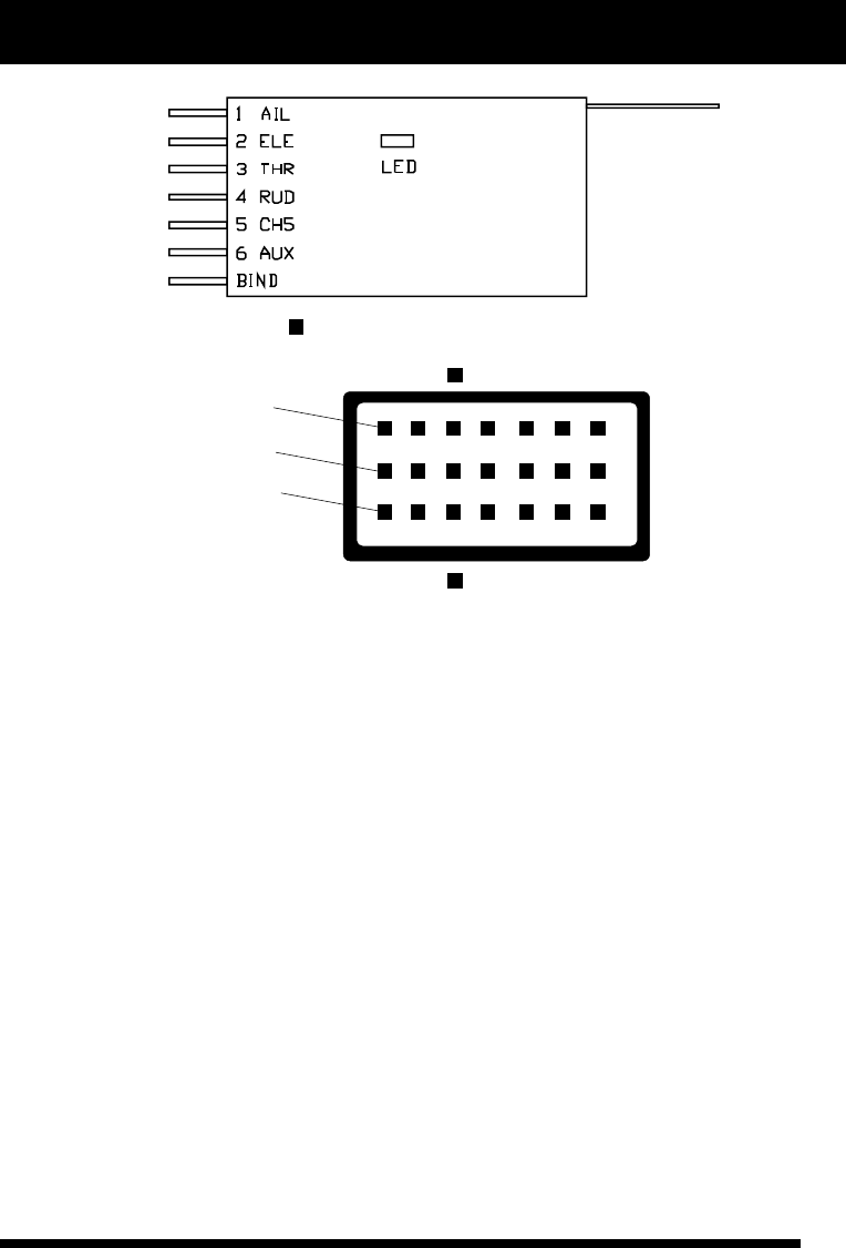
40
www.NineEagle.com
Operation and Instruction of 6-channel TX
X6
receiver front view
power line
signal line
base line
front
back
The front is with LED indicator light.
As illustration, “1 AIL” represents aileron channel, “2 ELE” represents elevator channel, “3 THR” represents
throttle channel, “4 RUD” represents rudder channel, “5 CH5” represents landing gear/sensitivity channel, “6
AUX” represents PITCH /flap channel, “BIND” represents binding/power faucet. The LED indicator light
displays the receiver status.
Turn on the power of TX first, and make the receiver connected with power, LED will go solid bright when the
receiver star ts to work. If there is no signal from TX within 2 seconds, the receiver will output signal as
illustration below, and then returns to signal search status with LED flashing fast.
AIL aileron 1500±20us
ELE elevator 1500±20us
THR throttle 1000±20us
RUD rudder 1500±20us
CH5 channel 5 1500±20us
AUX channel 6 1500±20us
If there are many remote control equipments working at the same time, please do as the following operation:
turn on the power of TX before receiver is connected with power, and make sure the TX is more than 0.6m away
from the receiver (close proximity is unfavorable). Make the receiver connected with power, and enlarge the
distance (about 1m to 2m) of TX and the receiver to test whether the movement of each direction is correct and
fluent when the receiver responds to TX. If the movement is not fluent, please turn on the power of TX again, and
the TX will re-choose idle channel to communicate. (This operation should be completed about 1.5m away from
the receiver without power.)