Nissan 2004 X Trail Owners Manual MTC
2015-10-23
: Nissan Nissan-2004-Nissan-X-Trail-Owners-Manual-818326 nissan-2004-nissan-x-trail-owners-manual-818326 nissan pdf
Open the PDF directly: View PDF ![]() .
.
Page Count: 36
- QUICK REFERENCE INDEX
- Table of Contents
- PRECAUTIONS
- TROUBLE DIAGNOSIS
- CONTROLLER
- BLOWER UNIT
- BLOWER MOTOR
- BLOWER FAN RESISTOR
- INTAKE DOOR MOTOR
- HEATER UNIT
- HEATER CORE
- MODE DOOR
- AIR MIX DOOR
- DUCTS AND GRILLES
- ELECTRICAL UNITS
- STANDARDIZED RELAY
- FUSE BLOCK - JUNCTION BOX (J/B)
- FUSE AND FUSIBLE LINK BOX

MTC-1
MANUAL AIR CONDITIONER
J AIR CONDITIONER
CONTENTS
C
D
E
F
G
H
I
K
L
M
SECTION
A
B
MTC
MANUAL AIR CONDITIONER
PRECAUTIONS .......................................................... 2
Precautions for Supplemental Restraint System
(SRS) “AIR BAG” and “SEAT BELT PRE-TEN-
SIONER” .................................................................. 2
Wiring Diagrams and Trouble Diagnosis .................. 2
TROUBLE DIAGNOSIS .............................................. 3
How to Perform Trouble Diagnoses for Quick and
Accurate Repair ....................................................... 3
WORK FLOW ........................................................ 3
SYMPTOM TABLE ................................................ 3
Component Parts and Harness Connector Location ..... 4
PASSENGER COMPARTMENT ........................... 4
Discharge Air Flow ................................................... 5
Wiring Diagram —HEATER— .................................. 6
Operational Check ................................................... 7
CHECKING BLOWER ........................................... 7
CHECKING DISCHARGE AIR .............................. 7
CHECKING RECIRCULATION ............................. 7
CHECKING TEMPERATURE DECREASE .......... 8
CHECKING TEMPERATURE INCREASE ............ 8
Mode Door ............................................................... 9
INSPECTION FLOW ............................................. 9
Air Mix Door ........................................................... 10
INSPECTION FLOW ........................................... 10
Intake Door Motor Circuit ........................................11
INSPECTION FLOW ............................................11
COMPONENT DESCRIPTION ............................11
DIAGNOSTIC PROCEDURE FOR INTAKE
DOOR MOTOR ................................................... 12
Blower Motor Circuit ............................................... 15
INSPECTION FLOW ........................................... 15
DIAGNOSTIC PROCEDURE FOR BLOWER
MOTOR ............................................................... 16
COMPONENT INSPECTION .............................. 18
Insufficient Heating ................................................. 19
INSPECTION FLOW ........................................... 19
CONTROLLER ......................................................... 21
Removal and Installation ........................................ 21
REMOVAL ........................................................... 21
INSTALLATION ................................................... 21
Disassembly and Assembly .................................... 21
BLOWER UNIT ......................................................... 22
Removal and Installation ........................................ 22
REMOVAL ........................................................... 22
INSTALLATION ................................................... 22
Disassembly and Assembly .................................... 23
BLOWER MOTOR .................................................... 24
Removal and Installation ........................................ 24
REMOVAL ........................................................... 24
INSTALLATION ................................................... 24
BLOWER FAN RESISTOR ....................................... 25
Removal and Installation ........................................ 25
REMOVAL ........................................................... 25
INSTALLATION ................................................... 25
INTAKE DOOR MOTOR ........................................... 26
Removal and Installation ........................................ 26
REMOVAL ........................................................... 26
INSTALLATION ................................................... 26
HEATER UNIT ........................................................... 27
Removal and Installation ........................................ 27
REMOVAL ........................................................... 27
INSTALLATION ................................................... 28
Disassembly and Assembly .................................... 29
HEATER CORE ......................................................... 30
Removal and Installation ........................................ 30
REMOVAL ........................................................... 30
INSTALLATION ................................................... 30
MODE DOOR ............................................................ 31
Control Linkage Adjustment ................................... 31
MODE DOOR CONTROL CABLE ....................... 31
AIR MIX DOOR ......................................................... 32
Control Linkage Adjustment ................................... 32
AIR MIX DOOR CONTROL CABLE .................... 32
DUCTS AND GRILLES ............................................. 33
Removal and Installation ........................................ 33
REMOVAL ........................................................... 33
INSTALLATION ................................................... 36

MTC-2
PRECAUTIONS
PRECAUTIONS PFP:00001
Precautions for Supplemental Restraint System (SRS) “AIR BAG” and “SEAT
BELT PRE-TENSIONER” EJS004L7
The Supplemental Restraint System such as “AIR BAG” and “SEAT BELT PRE-TENSIONER”, used along
with a front seat belt, helps to reduce the risk or severity of injury to the driver and front passenger for certain
types of collision. Information necessary to service the system safely is included in the SRS and SB section of
this Service Manual.
WARNING:
●To avoid rendering the SRS inoperative, which could increase the risk of personal injury or death
in the event of a collision which would result in air bag inflation, all maintenance must be per-
formed by an authorized NISSAN/INFINITI dealer.
●Improper maintenance, including incorrect removal and installation of the SRS, can lead to per-
sonal injury caused by unintentional activation of the system. For removal of Spiral Cable and Air
Bag Module, see the SRS section.
●Do not use electrical test equipment on any circuit related to the SRS unless instructed to in this
Service Manual. SRS wiring harnesses can be identified by yellow and/or orange harnesses or
harness connectors.
Wiring Diagrams and Trouble Diagnosis EJS000WA
When you read wiring diagrams, refer to the following:
●GI-14, "How to Read Wiring Diagrams" in GI section.
●PG-3, "Wiring Diagram - POWER -" in PG section.
When you perform trouble diagnosis, refer to the following:
●GI-10, "How to Follow Trouble Diagnoses" in GI section.
●GI-23, "How to Perform Efficient Diagnosis for an Electrical Incident" in GI section.
TROUBLE DIAGNOSIS
MTC-3
C
D
E
F
G
H
I
K
L
M
A
B
MTC
TROUBLE DIAGNOSIS PFP:00004
How to Perform Trouble Diagnoses for Quick and Accurate Repair EJS001FB
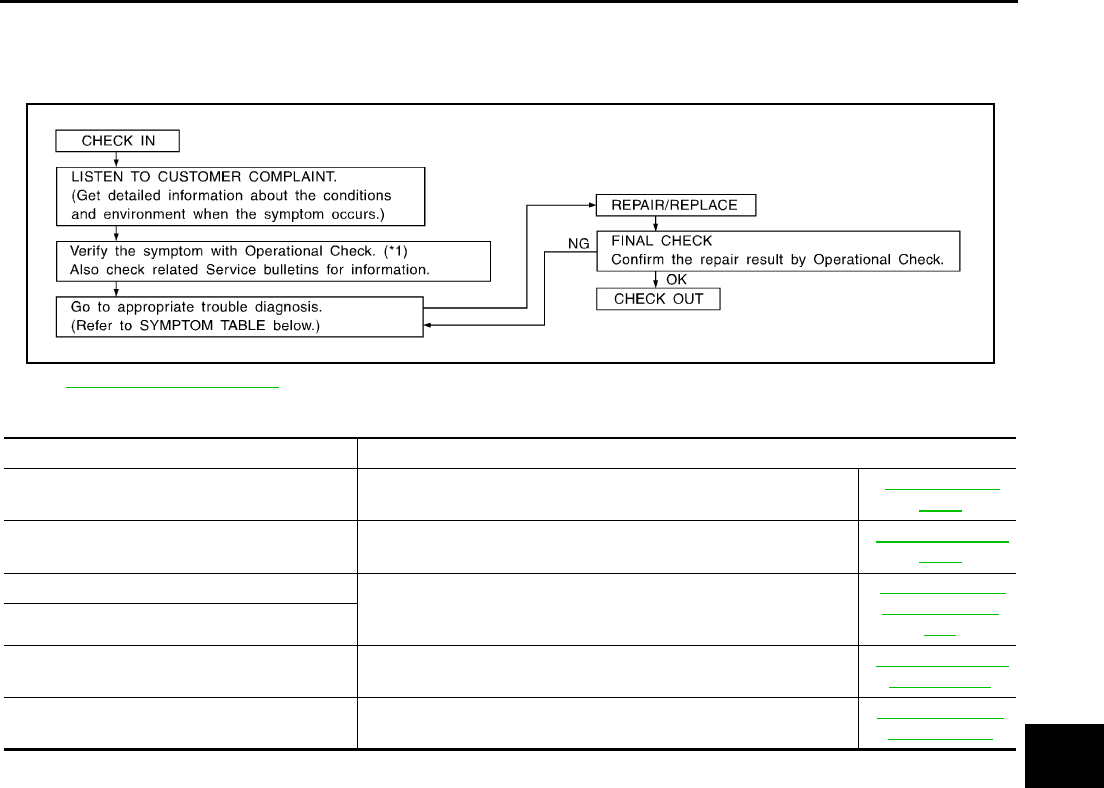
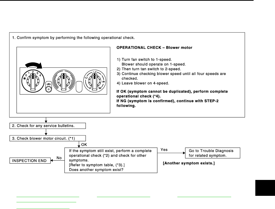
WORK FLOW
SYMPTOM TABLE
*1 MTC-7, "Operational Check".
SHA900E
Symptom Reference Page
Air outlet does not change. Go to Trouble Diagnosis Procedure for Mode Door. MTC-9, "Mode
Door"
Discharge air temperature does not change. Go to Trouble Diagnosis Procedure Air Mix Door. MTC-10, "Air Mix
Door"
Intake door does not change.
Go to Trouble Diagnosis Procedure for Intake Door Motor Circuit.
MTC-11, "Intake
Door Motor Cir-
cuit"
Intake door motor does not operate normally.
Blower motor operation is malfunctioning. Go to Trouble Diagnosis Procedure for Blower Motor Circuit. MTC-15, "Blower
Motor Circuit"
Insufficient heating Go to Trouble Diagnosis Procedure for Insufficient Heating. MTC-19, "Insuffi-
cient Heating"
MTC-4
TROUBLE DIAGNOSIS
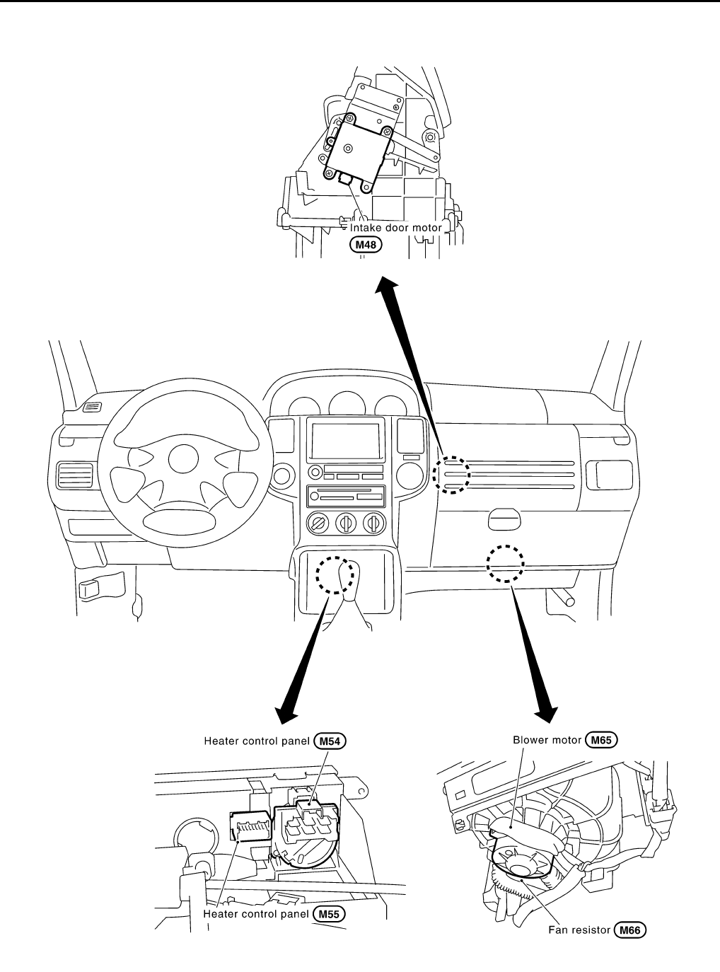
Component Parts and Harness Connector Location EJS001FC
PASSENGER COMPARTMENT
RJIA2845E
TROUBLE DIAGNOSIS
MTC-5
C
D
E
F
G
H
I
K
L
M
A
B
MTC
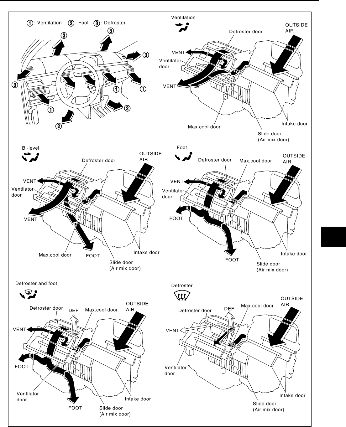
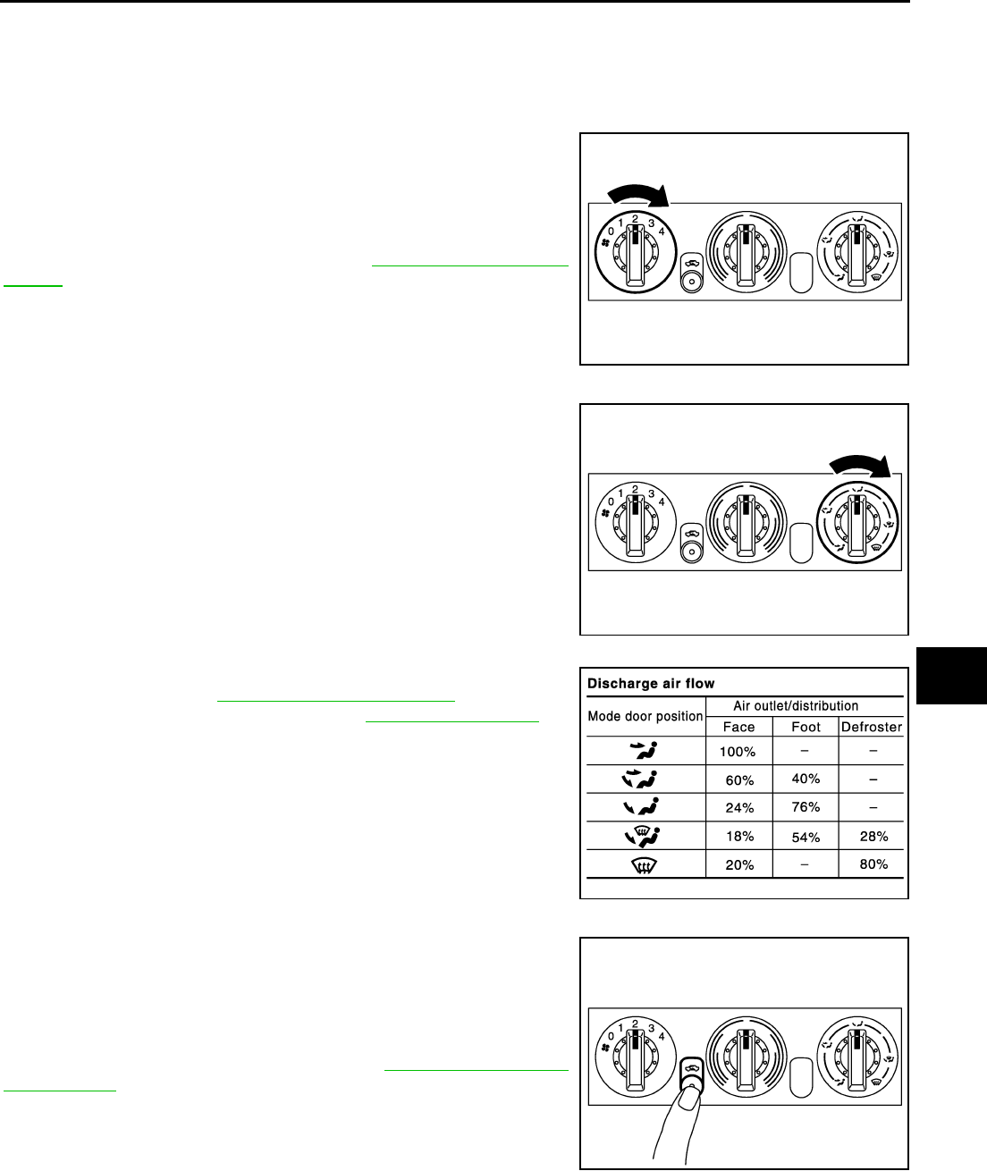
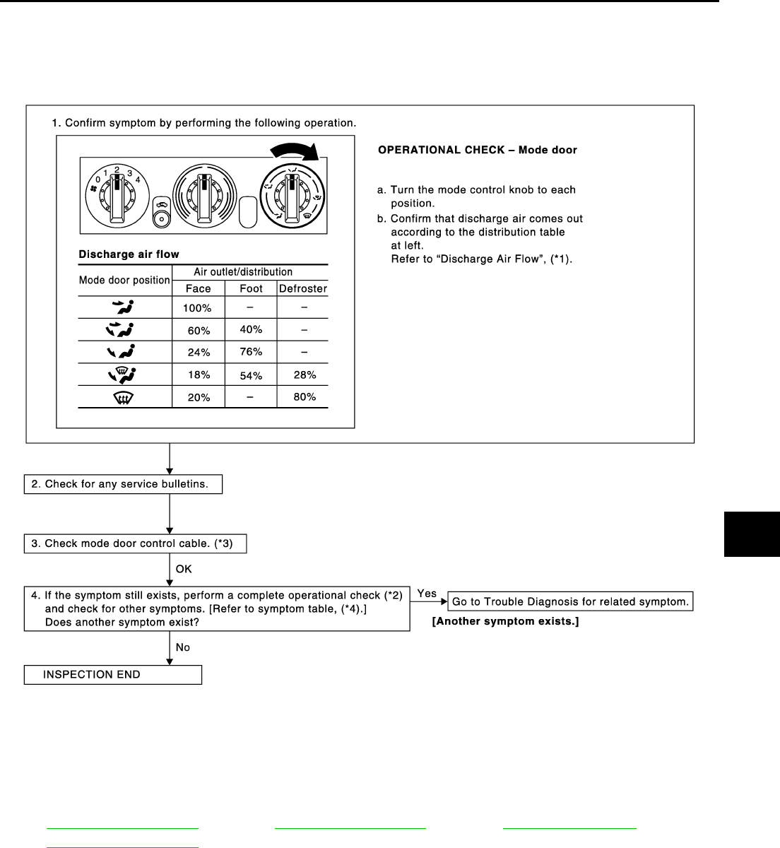
Discharge Air Flow EJS001HF
SJIA0441E
MTC-6
TROUBLE DIAGNOSIS
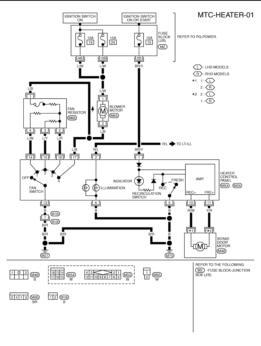
Wiring Diagram —HEATER— EJS001FD
TJWA0076E
TROUBLE DIAGNOSIS
MTC-7
C
D
E
F
G
H
I
K
L
M
A
B
MTC
Operational Check EJS001FE
The purpose of the operational check is to confirm that the system operates properly.
CHECKING BLOWER
1. Turn fan switch to 1st-speed. Blower should operate on low
speed.
2. Then turn fan switch to 2nd-speed, and continue checking
blower speed until all speeds are checked.
3. Leave blower on Max. speed.
If NG, go to trouble diagnosis procedure for MTC-15, "Blower Motor
Circuit" .
If OK, continue with the check.
CHECKING DISCHARGE AIR
1. Turn mode control dial to each position.
2. Confirm that discharge air comes out according to the air distri-
bution table. Refer to MTC-5, "Discharge Air Flow" .
If NG, go to trouble diagnosis procedure for MTC-9, "Mode Door" .
If OK, continue the check.
CHECKING RECIRCULATION
1. Press REC switch. Recirculation indicator should eliminate.
2. Press REC switch again. Recirculation indicator should not illu-
minate.
3. Listen for intake door position change (you should hear blower
sound change slightly).
If NG, go to trouble diagnosis procedure for MTC-11, "Intake Door
Motor Circuit" .
If OK, continue the check.
Conditions :Engine running at usual operating temperature
RJIA0587E
RJIA0588E
RJIA0492E
RJIA0589E
MTC-8
TROUBLE DIAGNOSIS
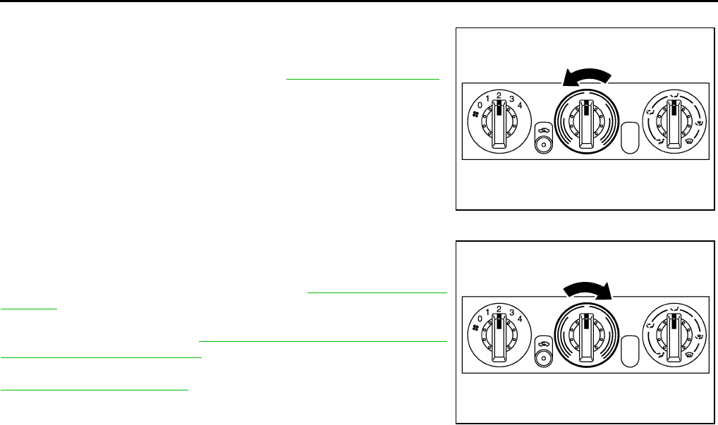
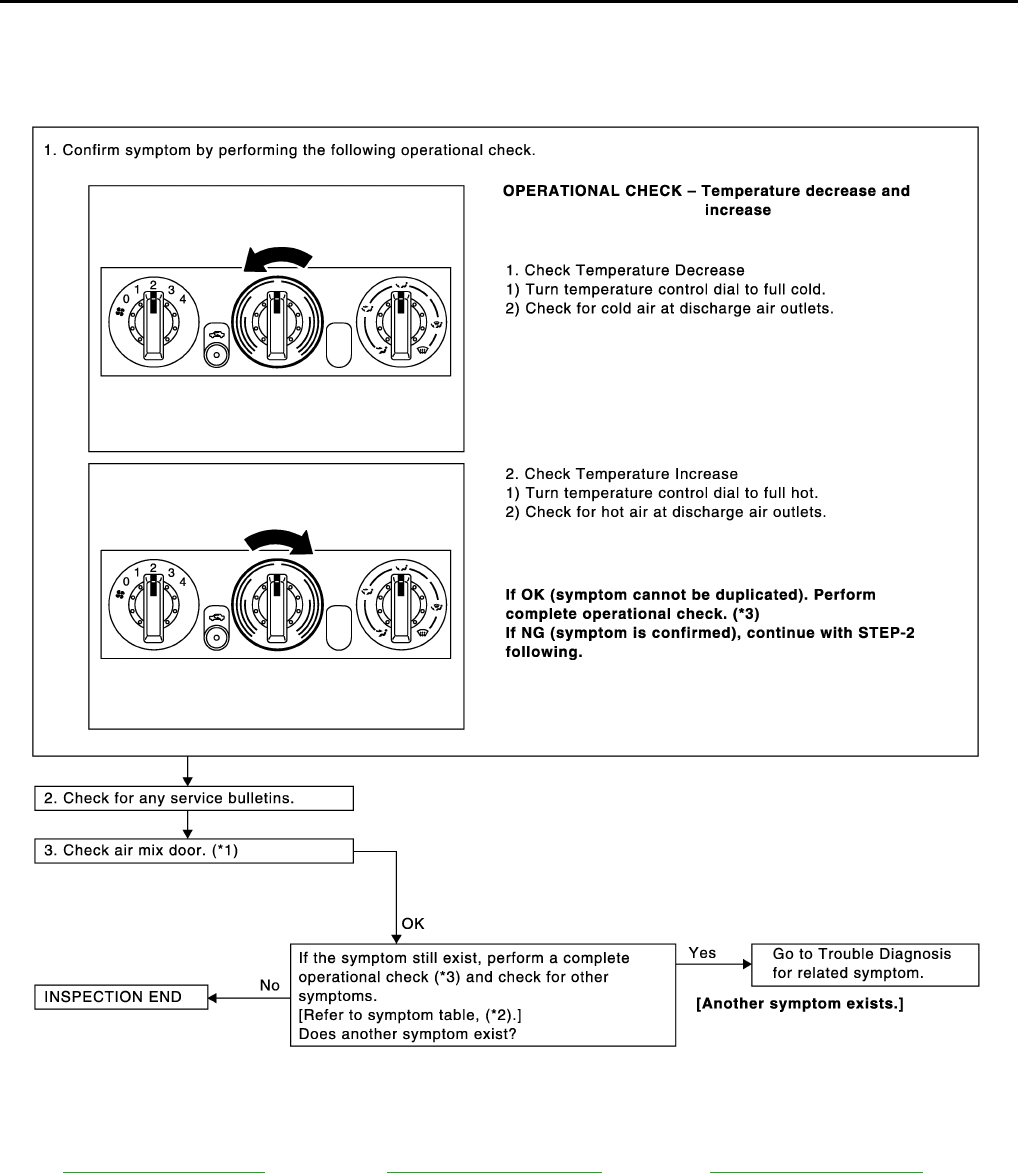
CHECKING TEMPERATURE DECREASE
1. Turn temperature control dial to full cold position.
2. Check for cold air at discharge air outlets.
If NG, go to trouble diagnosis procedure for MTC-10, "Air Mix Door"
If OK, continue the check.
CHECKING TEMPERATURE INCREASE
1. Turn temperature control dial to full hot position.
2. Check for hot air at discharge air outlets.
If NG, go to trouble diagnosis procedure for MTC-19, "Insufficient
Heating" .
If all operational check are OK (symptom cannot be duplicated), go
to Incident Simulation Tests in GI-23, "How to Perform Efficient Diag-
nosis for an Electrical Incident" and perform tests as outlined to sim-
ulate driving conditions environment. If symptom appears, refer to
MTC-3, "SYMPTOM TABLE" and perform applicable trouble diagno-
sis procedures.
RJIA0590E
RJIA0591E
TROUBLE DIAGNOSIS
MTC-11
C
D
E
F
G
H
I
K
L
M
A
B
MTC
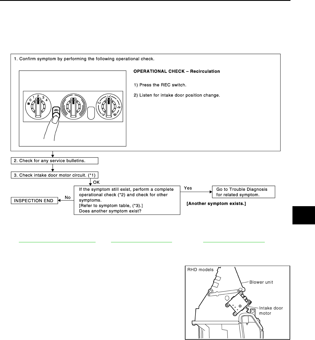
Intake Door Motor Circuit EJS004HC
SYMPTOM:
●Intake door does not change.
●Intake door motor does not operate normally.
INSPECTION FLOW
COMPONENT DESCRIPTION
Intake Door Motor
The intake door motor is attached to the intake unit. It rotates so that
air is drawn from inlets set by the heater control panel. Motor rotation
is conveyed to a lever which activates the intake door.
*1 MTC-11, "Intake Door Motor Circuit".*2 MTC-7, "Operational Check".*3MTC-3, "SYMPTOM TABLE".
RJIA0594E
RJIA0519E
MTC-12
TROUBLE DIAGNOSIS
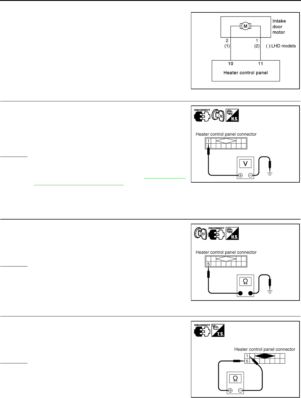
DIAGNOSTIC PROCEDURE FOR INTAKE DOOR MOTOR
SYMPTOM: Intake door does not operate normally.
1. CHECK POWER SUPPLY FOR HEATER CONTROL PANEL
1. Disconnect heater control panel connector.
2. Turn ignition switch ON.
3. Check voltage between heater control panel harness connector
M55 terminal 1 (BR/Y) and ground.
OK or NG
OK >> GO TO 2.
NG >> Check power supply circuit and 10 A fuse [No. 15,
located in the fuse block (J/B)]. Refer to PG-75, "FUSE
BLOCK - JUNCTION BOX (J/B)" .
●If OK, check harness for open circuit. Repair or replace if necessary.
●If NG, replace fuse and check harness for short circuit. Repair or replace if necessary.
2. CHECK GROUND CIRCUIT FOR HEATER CONTROL PANEL
1. Turn ignition switch OFF.
2. Check continuity between heater control panel harness connec-
tor M55 terminal 5 (B) and ground.
OK or NG
OK >> GO TO 3.
NG >> Repair harness or connector.
3. CHECK RECIRCULATION SWITCH CIRCUIT
1. Press REC (recirculation) switch.
2. Check continuity between heater control panel harness connec-
tor M55 terminal 1 (BR/Y) and 5 (B).
OK or NG
OK >> GO TO 4.
NG >> Replace heater control panel.
RJIA2846E
1 – Ground : Battery voltage
RJIA2923E
5 – Ground : Continuity should exist.
RJIA2924E
1 (−) – 5 (+) : Continuity should exist.
RJIA2925E
TROUBLE DIAGNOSIS
MTC-13
C
D
E
F
G
H
I
K
L
M
A
B
MTC
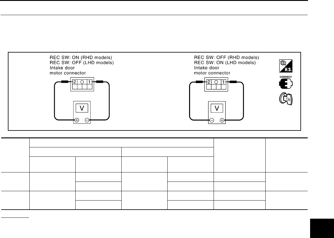
4. CHECK POWER SUPPLY FOR INTAKE DOOR MOTOR
1. Reconnect heater control panel connector.
2. Turn ignition switch ON.
3. Check voltage between intake door motor harness connector M48 terminal 1 (Y/R: RHD models, R/W:
LHD models) and 2 (R/W: RHD models, L/R: LHD models).
OK or NG
OK >> Replace intake door motor.
NG >> GO TO 5.
Model
Terminals
Condition Voltage
(+) (-)
Intake door motor
connector
Terminal No.
(wire color)
Intake door motor
connector
Terminal No.
(wire color)
RHD
models M48 2 (R/W) M48 1 (Y/R) REC SW: ON Approx. 12V
1 (Y/R) 2 (R/W) REC SW: OFF
LHD
models M48 1 (R/W) M48 2 (Y/R) REC SW: ON Approx. 12V
2 (Y/R) 1 (R/W) REC SW: OFF
RJIA2847E
MTC-14
TROUBLE DIAGNOSIS
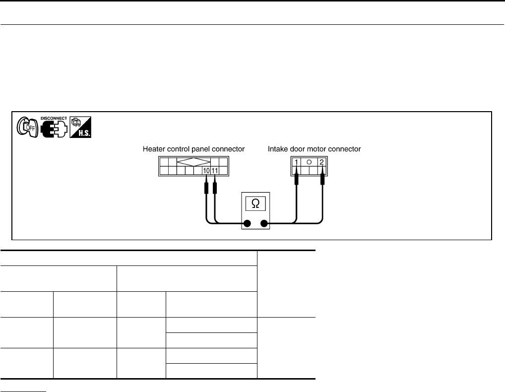
5. CHECK CIRCUIT CONTINUITY BETWEEN HEATER CONTROL PANEL AND INTAKE DOOR MOTOR
1. Turn ignition switch OFF.
2. Disconnect heater control panel connector and intake door motor connector.
3. Check continuity between heater control panel harness connector M55 terminal 10 (R/W) and intake door
motor harness connector M48 terminal 2 (R/W: RHD models) or 1 (R/W: LHD models).
4. Check continuity between heater control panel harness connector M55 terminal 11 (Y/R) and intake door
motor harness connector M48 terminal 1 (Y/R: RHD models) or 2 (Y/R: LHD models).
OK or NG
OK >> Replace heater control panel.
NG >> Repair harness or connector.
Terminals
Continuity
Heater control panel connec-
tor Intake door motor connector
Connector Terminal No.
(wire color) Connector Terminal No.
(wire color)
M55 10 (R/W) M48
2 (R/W): RHD models
Yes
1 (R/W): LHD models
M55 11 (Y/R) M48 1 (Y/R): RHD models
2 (Y/R): LHD models
RJIA3145E
MTC-16
TROUBLE DIAGNOSIS
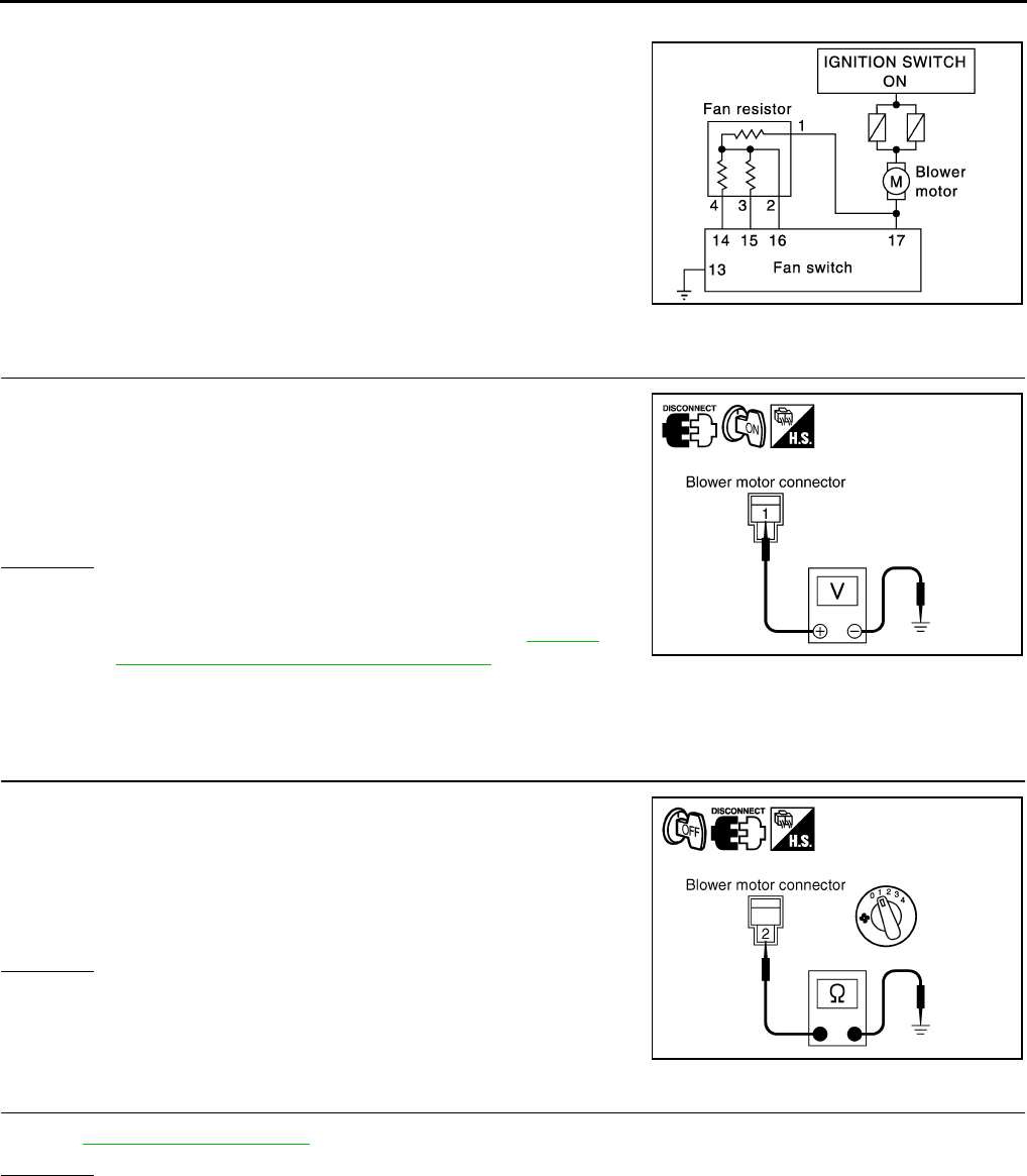
DIAGNOSTIC PROCEDURE FOR BLOWER MOTOR
SYMPTOM: Blower motor operation is malfunctioning.
1. CHECK POWER SUPPLY FOR BLOWER MOTOR
1. Disconnect blower motor connector.
2. Turn ignition switch ON.
3. Check voltage between blower motor harness connector M65
terminal 1 (L/W) and ground.
OK or NG
OK >> GO TO 2.
NG >> Check power supply circuit and 15A fuses [Nos. 19 and
24, located in the fuse block (J/B)]. Refer to PG-75,
"FUSE BLOCK - JUNCTION BOX (J/B)" .
●If OK, check harness for open circuit. Repair or replace if necessary.
●If NG, replace fuse and check harness for short circuit. Repair or replace if necessary.
2. CHECK GROUND CIRCUIT FOR BLOWER MOTOR
1. Turn ignition switch OFF.
2. Turn fan switch to 1-speed.
3. Check continuity between blower motor harness connector M65
terminal 2 (L/B) and ground.
OK or NG
OK >> GO TO 3.
NG >> GO TO 4.
3. CHECK BLOWER MOTOR
Refer to MTC-18, "Blower Motor" .
OK or NG
OK >> INSPECTION END
NG >> Replace blower motor.
RJIA0602E
1 – Ground : Battery voltage
RJIA2929E
2 – Ground : Continuity should exist.
RJIA2930E
TROUBLE DIAGNOSIS
MTC-17
C
D
E
F
G
H
I
K
L
M
A
B
MTC
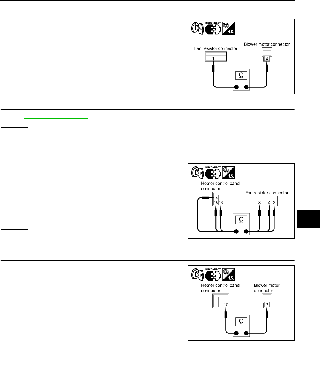
4. CHECK CIRCUIT CONTINUITY BETWEEN BLOWER MOTOR AND FAN RESISTOR
1. Disconnect fan resistor connector.
2. Check continuity between fan resistor harness connector M66
terminal 1 (L/B) and blower motor harness connector M65 termi-
nal 2 (L/B).
OK or NG
OK >> GO TO 5.
NG >> Repair harness or connector.
5. CHECK FAN RESISTOR
Refer to MTC-18, "Fan Resistor" .
OK or NG
OK >> GO TO 6.
NG >> Replace fan resistor.
6. CHECK CIRCUIT CONTINUITY BETWEEN FAN RESISTOR AND HEATER CONTROL PANEL
1. Disconnect heater control panel connector.
2. Check continuity between fan resistor harness connector M66
terminal 2 (L/R), 3 (L/Y) or 4 (L/W) and heater control panel har-
ness connector M54 terminal 14 (L/W), 15 (L/Y) or 16 (L/R).
OK or NG
OK >> GO TO 7.
NG >> Repair harness or connector.
7. CHECK CIRCUIT CONTINUITY BETWEEN BLOWER MOTOR AND HEATER CONTROL PANEL
Check continuity between blower motor harness connector M65 ter-
minal 2 (L/B) and heater control panel harness connector M54 termi-
nal 17 (L/B).
OK or NG
OK >> GO TO 8.
NG >> Repair harness or connector.
8. CHECK FAN SWITCH
Refer to MTC-18, "Fan Switch" .
OK or NG
OK >> GO TO 9.
NG >> Replace fan switch.
1 – 2 : Continuity should exist.
RJIA2931E
2 – 16 : Continuity should exist.
3 – 15 : Continuity should exist.
4 – 14 : Continuity should exist.
RJIA2932E
2 – 17 : Continuity should exist.
RJIA2933E
MTC-18
TROUBLE DIAGNOSIS
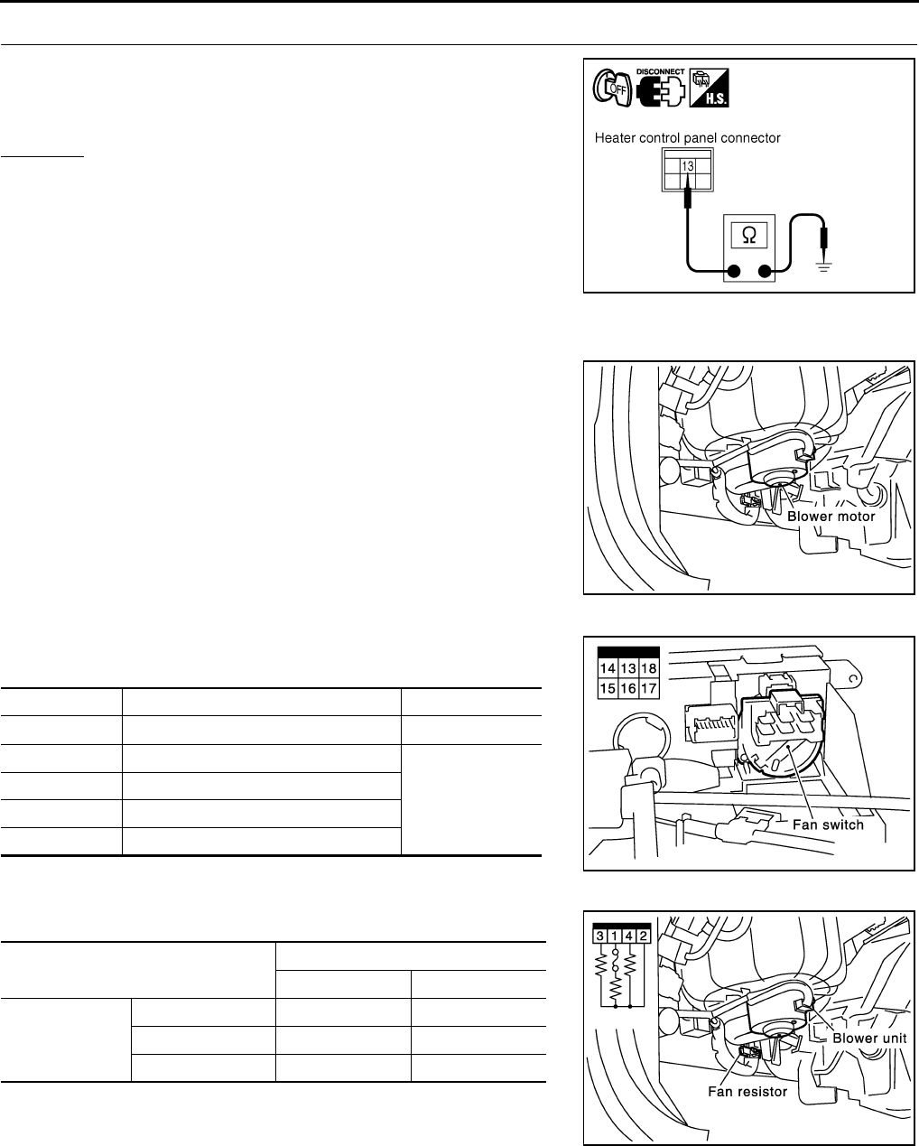
9. CHECK GROUND CIRCUIT
Check continuity between heater control panel harness connector
M54 terminal 13 (B) and ground.
OK or NG
OK >> INSPECTION END
NG >> Repair harness or connector.
COMPONENT INSPECTION
Blower Motor
Confirm smooth rotation of the blower motor.
●Ensure that there are no foreign particles inside the intake unit.
Fan Switch
Check continuity between heater control connector M54 terminals at
each switch position.
Fan Resistor
Check resistance between fan resister connector M66 terminals.
13 – Ground : Continuity should exist.
RJIA2934E
RJIA0609E
Switch position Terminals Continuity
OFF 13 - 14, 15, 16, 17 No
1 13 - 14
Yes
2 13 - 15
3 13 - 16
4 13 - 17
RJIA0610E
Terminals Resistance (Ω)
LHD RHD
1
2 0.25 - 0.31 0.28 - 0.34
3 0.58 - 0.70 0.79 - 0.97
4 1.33 - 1.63 1.84 - 2.24
RJIA0611E
TROUBLE DIAGNOSIS
MTC-19
C
D
E
F
G
H
I
K
L
M
A
B
MTC
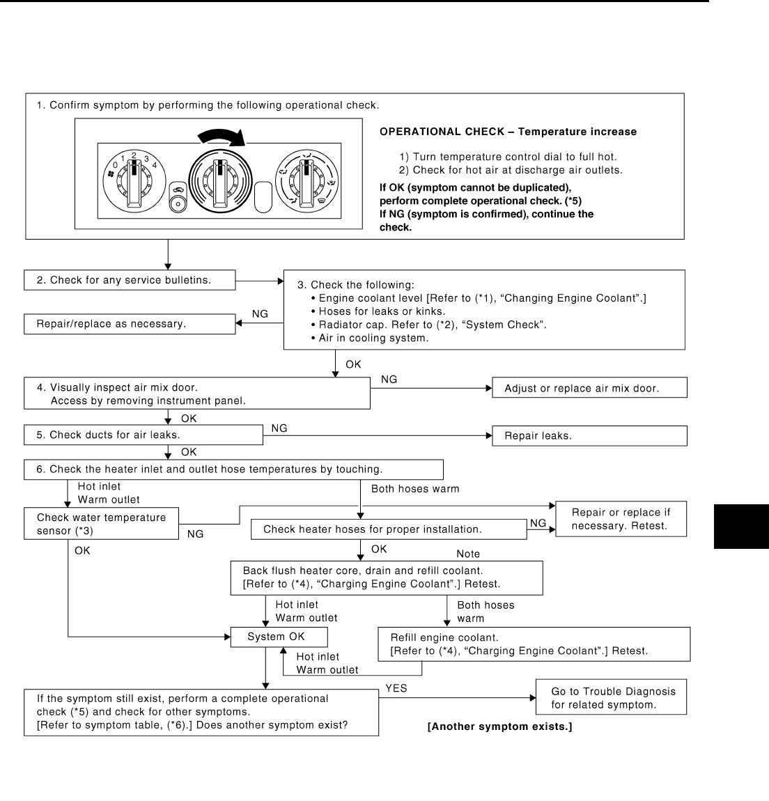
Insufficient Heating EJS001FJ
SYMPTOM: Insufficient heating
INSPECTION FLOW
SJIA0482E

MTC-20
TROUBLE DIAGNOSIS
*1 QR engine; CO-9, "Changing Engine
Coolant" or YD engine; CO-31,
"Changing Engine Coolant" .
*2 QR engine; CO-13, "Checking Radi-
ator Cap" or YD engine; CO-35,
"Checking Radiator Cap" .
*3 QR engine; (WITH EURO-OBD) EC-
162, "DTC P0117, P0118 ECT SEN-
SOR" .
QR engine; (WITHOUT EURO-OBD)
EC-597, "DTC P0117, P0118 ECT
SENSOR" .
YD engine; (WITH EURO-OBD) EC-
981, "DTC P0117, P0118 ECT SEN-
SOR" .
YD engine; (WITHOUT EURO-OBD)
EC-1291, "DTC P0117, P0118 ECT
SENSOR" .
*4 QR engine; CO-9, "Changing Engine
Coolant" or YD engine; CO-31,
"Changing Engine Coolant" .
*5 MTC-7, "Operational Check" .*6MTC-3, "SYMPTOM TABLE".
CONTROLLER
MTC-21
C
D
E
F
G
H
I
K
L
M
A
B
MTC
CONTROLLER PFP:27500
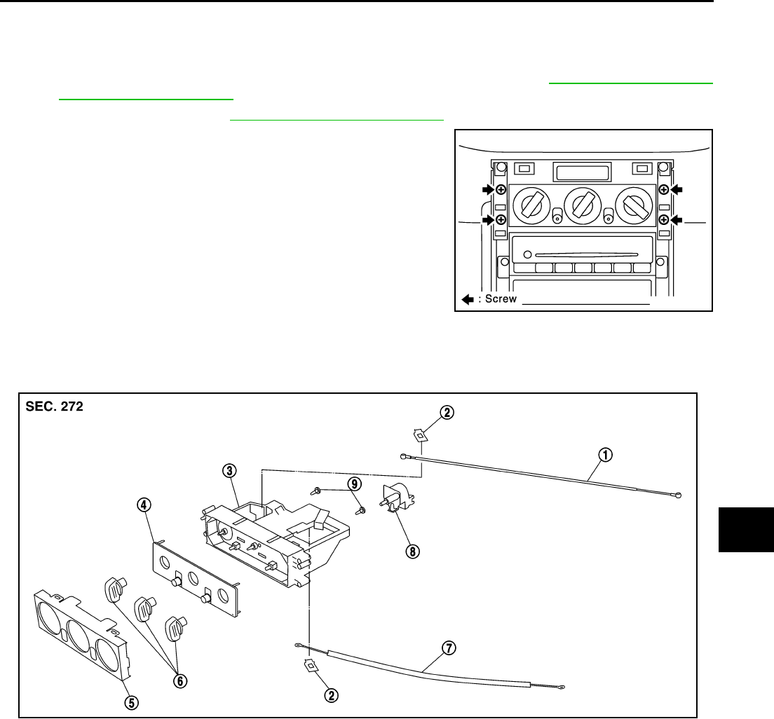
Removal and Installation EJS004HA
REMOVAL
1. Remove mode control cable and air mix control cable from heater unit. Refer to MTC-31, "MODE DOOR"
and MTC-32, "AIR MIX DOOR" .
2. Remove cluster lid C. Refer to IP-11, "Removal and Installation" .
3. Remove mounting screws from heater control panel.
4. Remove heater control panel, and then remove heater control
panel connector.
INSTALLATION
Installation is basically the reverse order of removal.
Disassembly and Assembly EJS004HB
RJIA0089E
1. Mode door cable 2. Clamp 3. Case assembly
4. Heater panel 5. Finisher 6. Dial
7. Air mix door cable 8. Fan switch 9. Bulb
RJIA3153E
MTC-22
BLOWER UNIT
BLOWER UNIT PFP:27200
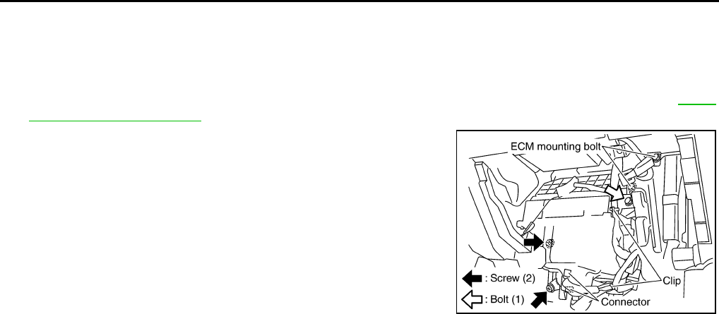
Removal and Installation EJS004YB
REMOVAL
1. Remove glove box assembly.
2. Remove glove box cover, instrument passenger lower panel and instrument reinforcement. Refer to IP-11,
"Removal and Installation" .
3. Remove ECM with ECM bracket attached.
4. Remove instrument panel mounting screw.
5. Remove blower unit mounting bolt and screw.
6. Disconnect blower motor connector and fan resistor connector.
7. Disconnect intake door motor connector and harness clips.
8. Remove blower unit.
CAUTION:
Slide the blower unit toward the right, remove location pins
(2 pieces), then move it downward.
INSTALLATION
Installation is basically the reverse order of removal.
CAUTION:
●Make sure location pins (2 pieces) are securely installed.
RJIA3161E
BLOWER UNIT
MTC-23
C
D
E
F
G
H
I
K
L
M
A
B
MTC
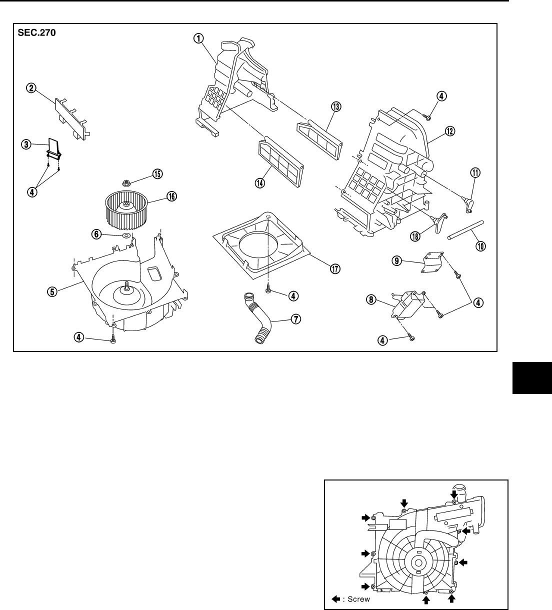
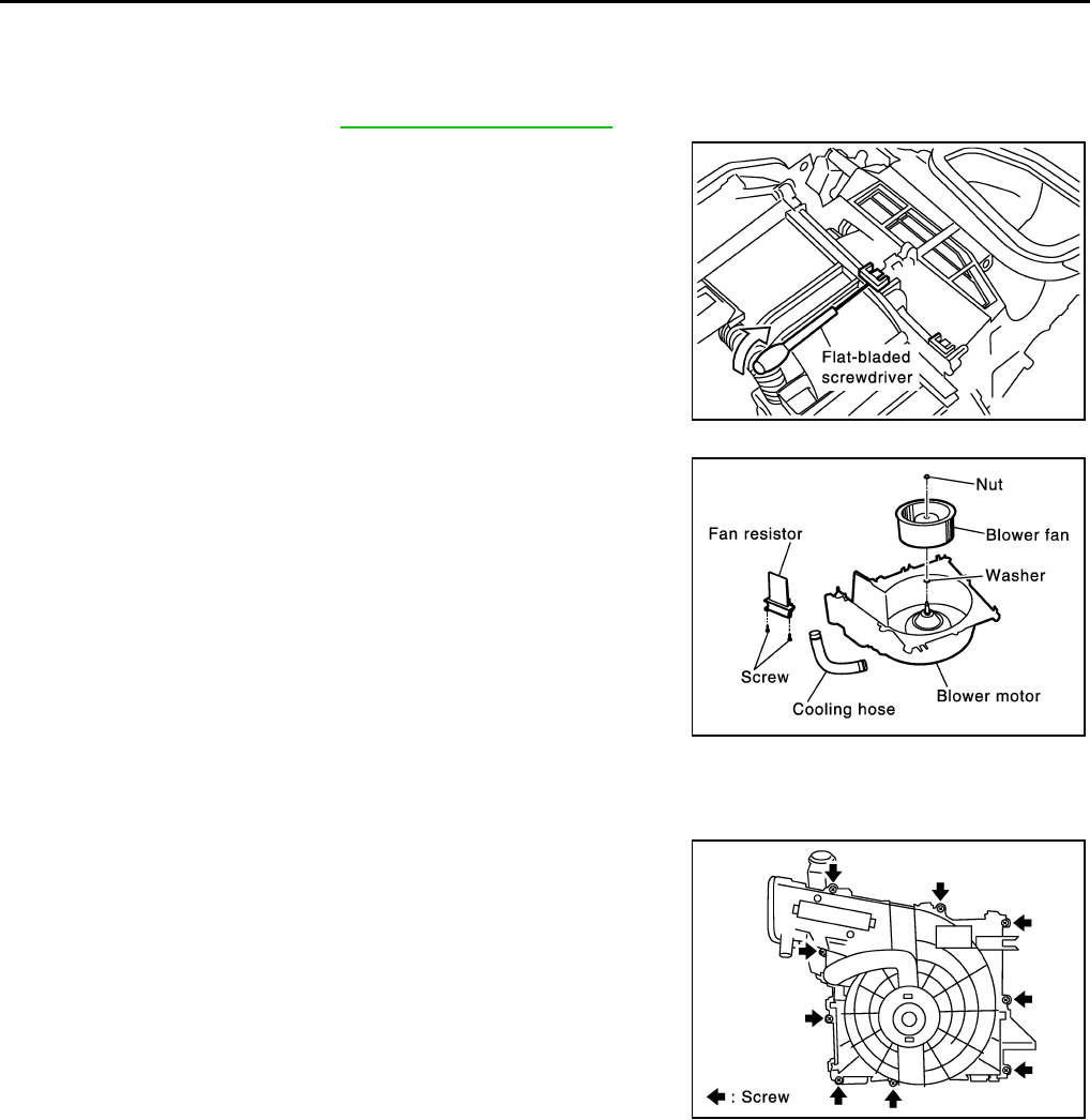
Disassembly and Assembly EJS004YC
NOTE:
This illustration is for LHD models. The layout for RHD models is symmetrically opposite.
CAUTION:
If retaining tabs are damaged while disassembling blower unit,
use 9 screws (27111-2Y000) to assemble blower unit.
1. Upper case 2 2. Filter cover 3. Fan resistor
4. Screw 5. Blower fan motor assembly 6. Washer
7. Cooling hose 8. Intake door motor 9. Motor bracket
10. Intake door link 11. Intake door lever 2 12. Upper case 1
13. Intake door 2 14. Intake door 1 15. Nut
16. Blower fan 17. Bell mouth 18. Intake door lever 1
SJIA0483E
RJIA3155E
MTC-24
BLOWER MOTOR
BLOWER MOTOR PFP:27226
Removal and Installation EJS004HD
REMOVAL
1. Remove blower unit. Refer to ATC-125, "BLOWER UNIT" .
2. Separate blower unit.
3. Remove cooling hose, fan resistor and blower fan.
INSTALLATION
Installation is basically the reverse order of removal.
CAUTION:
If retaining tabs are damaged while disassembling blower unit,
use 9 screws (27111-2Y000) to assemble blower unit.
RJIA0054E
RJIA0092E
RJIA0097E
BLOWER FAN RESISTOR
MTC-25
C
D
E
F
G
H
I
K
L
M
A
B
MTC
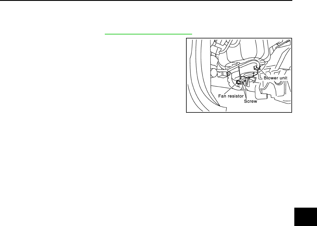
BLOWER FAN RESISTOR PFP:27150
Removal and Installation EJS004HE
REMOVAL
1. Remove glove box cover. Refer to IP-11, "Removal and Installation" .
2. Remove mounting screws, and then remove fan resistor.
CAUTION:
Do not repair the thermal fuse of the fan resistor.
INSTALLATION
Installation is basically the reverse order of removal.
RJIA0093E
MTC-26
INTAKE DOOR MOTOR
INTAKE DOOR MOTOR PFP:27730
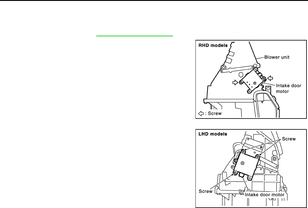
Removal and Installation EJS004HG
REMOVAL
1. Remove blower unit. Refer to ATC-125, "BLOWER UNIT" .
2. Remove mounting screws, and then remove intake door motor
from blower unit.
INSTALLATION
Installation is basically the reverse order of removal.
RJIA0056E
RJIA0571E
HEATER UNIT
MTC-27
C
D
E
F
G
H
I
K
L
M
A
B
MTC
HEATER UNIT PFP:27100
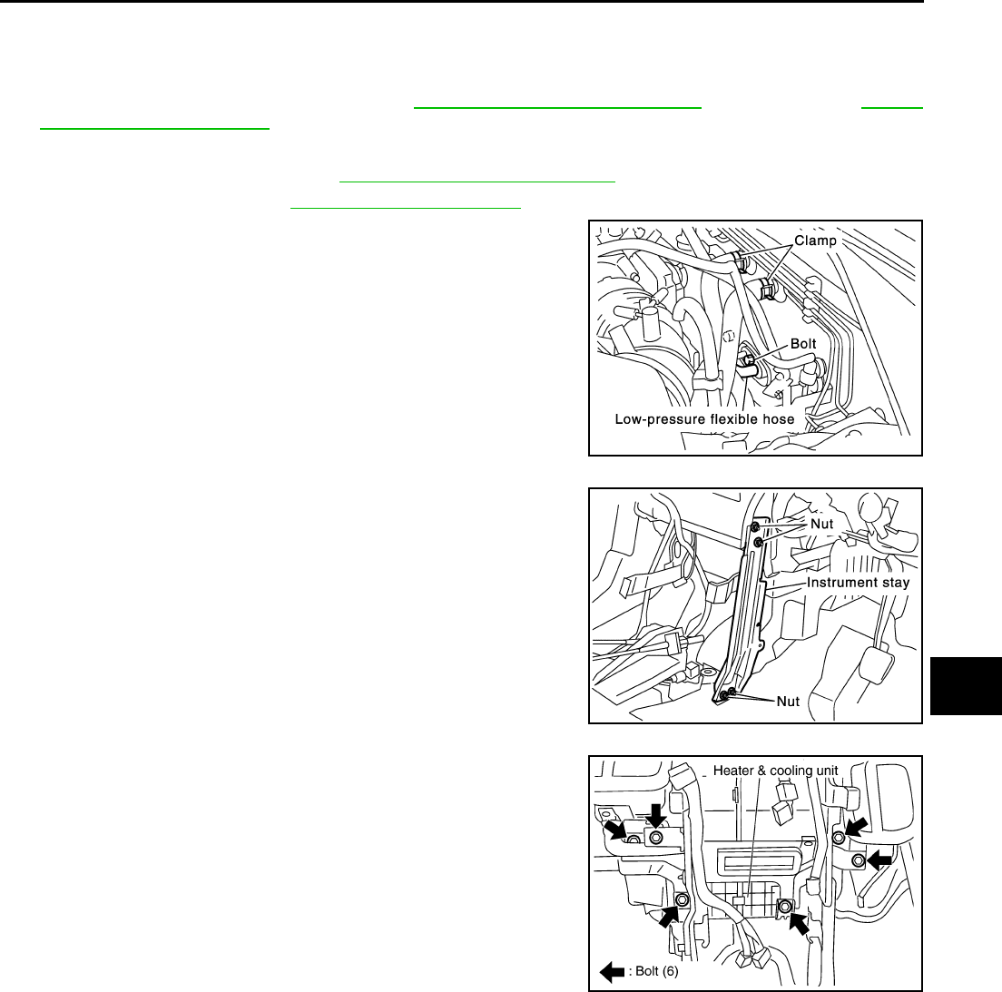
Removal and Installation EJS001F9
REMOVAL
1. Drain coolant from cooling system. Refer to CO-9, "Changing Engine Coolant" for QR engine or CO-31,
"Changing Engine Coolant" for YD engine.
2. Disconnect two heater hoses from heater core pipe.
3. Remove instrument panel. Refer to IP-11, "Removal and Installation" .
4. Remove blower unit. Refer to ATC-125, "BLOWER UNIT" .
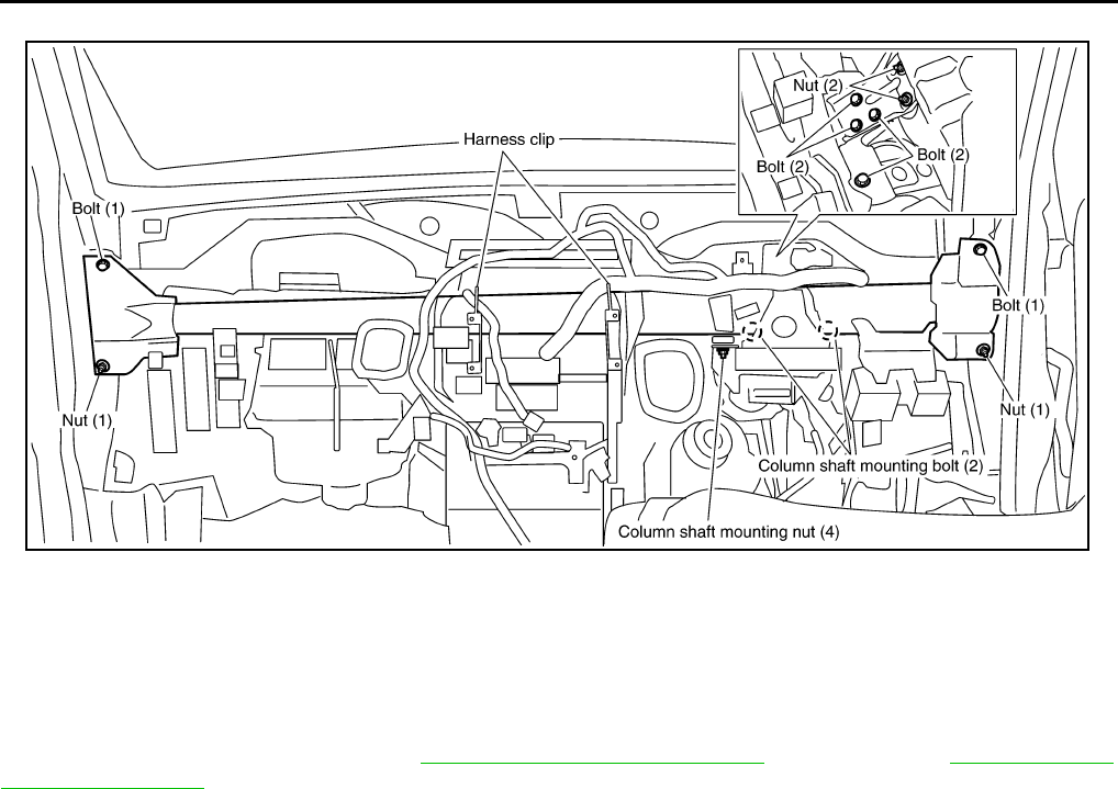
5. Remove clips of vehicle harness from steering member.
6. Remove mounting nuts, and then remove instrument stay.
7. Remove mounting bolts from heater (& cooling) unit.
RJIA0060E
RJIA0061E
RJIA2444E
MTC-28
HEATER UNIT
8. Remove steering member.
NOTE:
This illustration is for RHD models. The layout for LHD models is symmetrically opposite.
9. Remove heater unit.
INSTALLATION
Installation is basically the reverse order of removal.
NOTE:
When filling radiator with coolant, refer to CO-9, "Changing Engine Coolant" for QR engine or CO-31, "Chang-
ing Engine Coolant" for YD engine.
RJIA2404E
HEATER UNIT
MTC-29
C
D
E
F
G
H
I
K
L
M
A
B
MTC
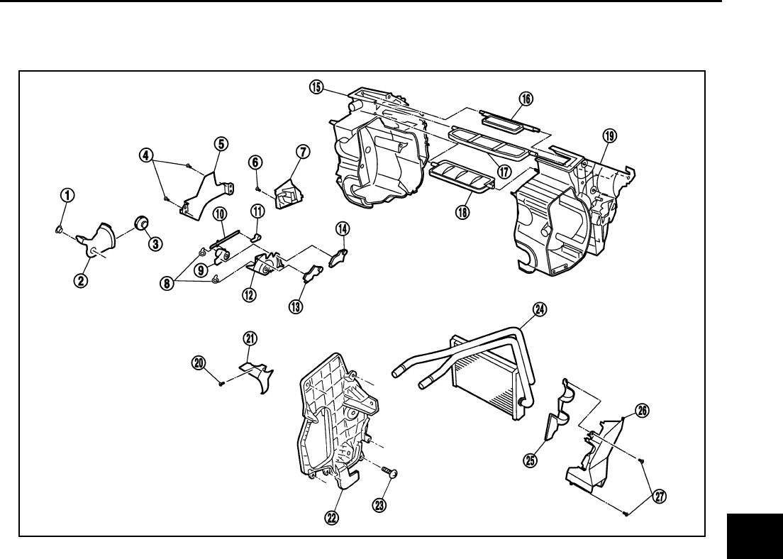
Disassembly and Assembly EJS001FA
NOTE:
This illustration is for RHD models. The layout for LHD models is symmetrically opposite.
1. Screw 2. Air mix door link 3. Air mix door gear
4. Screw 5. Cable bracket 6. Screw
7. Foot duct (right side) 8. Screw 9. Ventilator door link 2
10. Ventilator door link 2 11. Ventilator door lever 12. Main link
13. Max. cool door lever 14. Defroster door lever 15. Heater case (right side)
16. Defroster door 17. Ventilator door 18. Max. cool door
19. Heater case (left side) 20. Screw 21. Heater pipe support
22. Evaporator cover 23. Screw 24. Heater core
25. Heater core cover 26. Foot duct (left side) 27. Screw
RJIA0613E
MTC-30
HEATER CORE
HEATER CORE PFP:27140
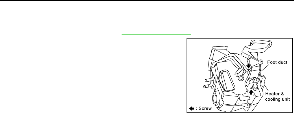
Removal and Installation EJS004HF
REMOVAL
1. Remove heater (& cooling) unit. Refer to MTC-27, "HEATER UNIT" .
2. Remove heater pipe support.
3. Remove mounting screws, and then remove foot duct and
heater core cover.
4. Remove heater core from heater (& cooling) unit.
INSTALLATION
Installation is basically the reverse order of removal.
RJIA0069E
MODE DOOR
MTC-31
C
D
E
F
G
H
I
K
L
M
A
B
MTC
MODE DOOR PFP:27181
Control Linkage Adjustment EJS001DA
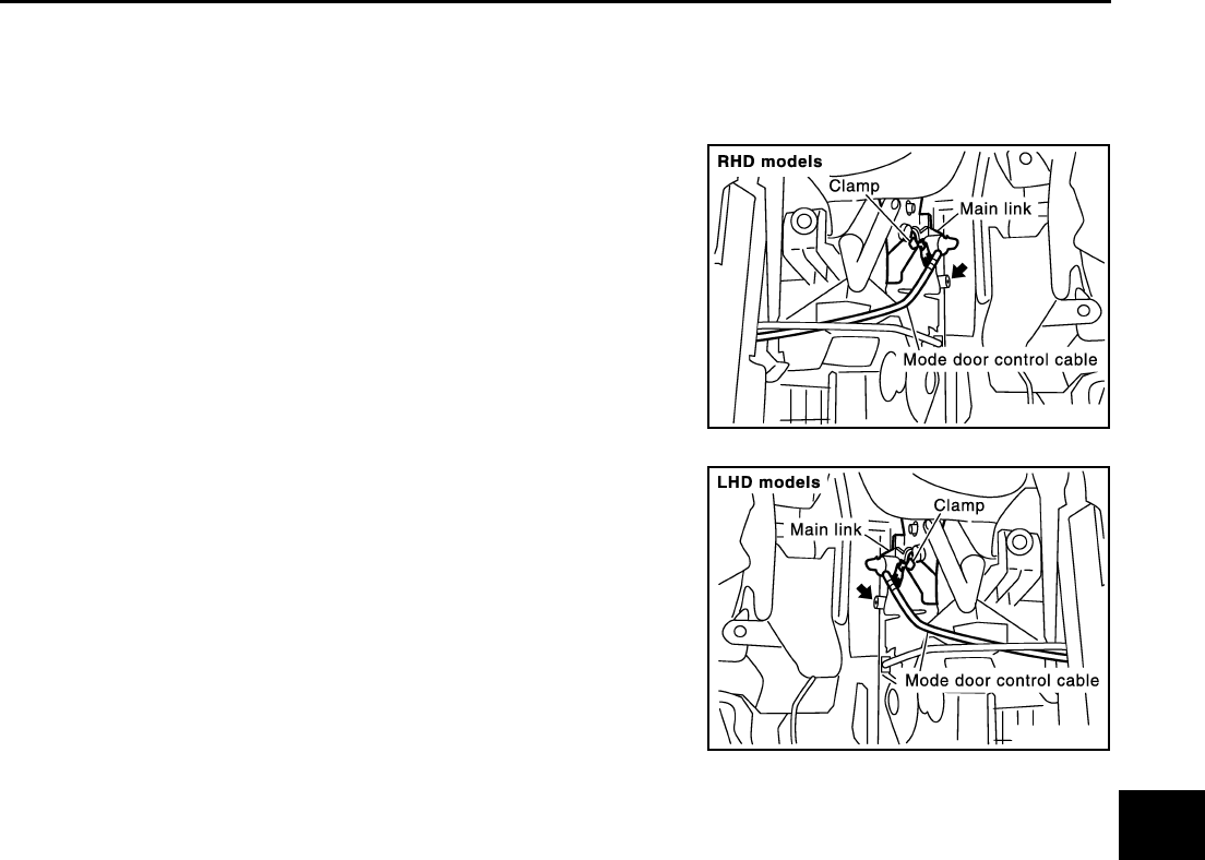
MODE DOOR CONTROL CABLE
1. Turn the mode control dial to VENT position.
2. Move side link by hand and hold mode door in VENT position.
3. Pull on the cable cover in the direction of the arrow, and then
clamp it.
NOTE:
After positioning control cable, make sure it operates properly.
RJIA0095E
RJIA0614E
MTC-32
AIR MIX DOOR
AIR MIX DOOR PFP:27180
Control Linkage Adjustment EJS001DB
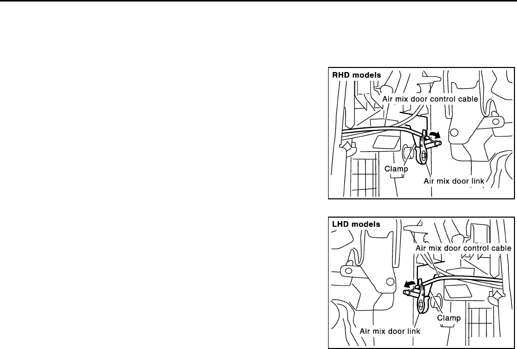
AIR MIX DOOR CONTROL CABLE
1. Turn the temperature control dial to full cold position.
2. Move air mix door lever by hand and hold it at the full cold posi-
tion.
3. Pull on the cable cover in the direction of the arrow, and then
clamp it.
NOTE:
After positioning control cable, make sure it operates properly.
RJIA0085E
RJIA0615E
DUCTS AND GRILLES
MTC-33
C
D
E
F
G
H
I
K
L
M
A
B
MTC
DUCTS AND GRILLES PFP:27860
Removal and Installation EJS004HH
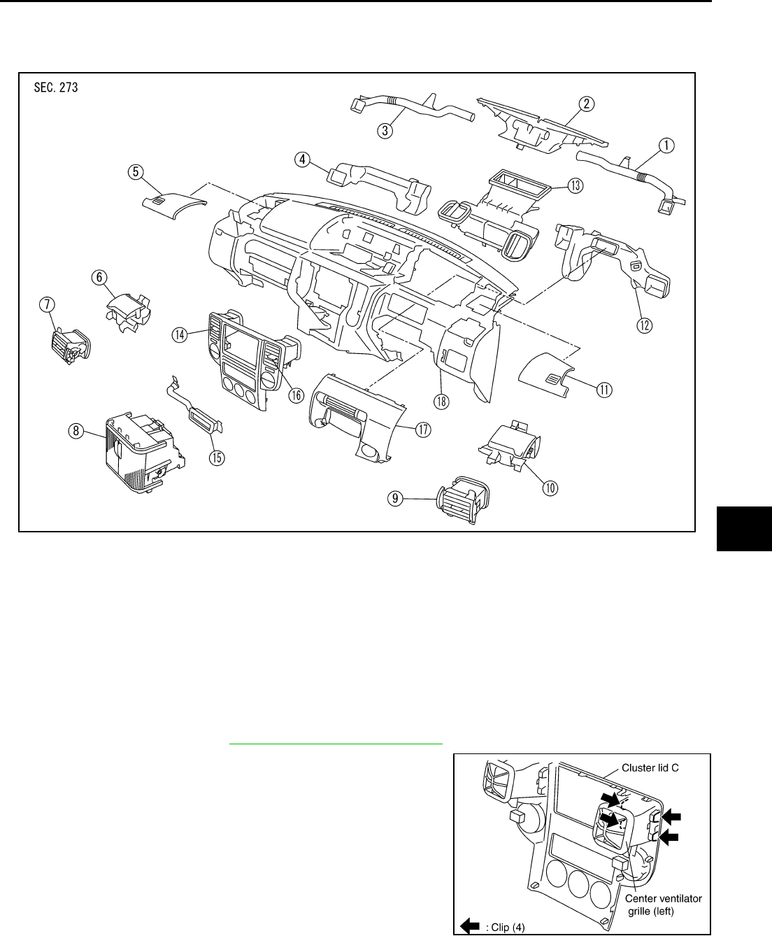
REMOVAL
NOTE:
This illustration is for RHD models. The layout for LHD models is symmetrically opposite.
Removal of Center Ventilator Grille
1. Remove cluster lid C. Refer to IP-11, "Removal and Installation" .
2. Remove mounting clips, and then remove center ventilator grille.
1. Side defroster duct (right) 2. Defroster nozzle 3. Side defroster duct (left)
4. Side ventilator duct (left) 5. Front speaker grille (left) 6. Cup holder (left)
7. Side ventilator grille (left) 8. Multi-box (Instrument center lower
panel)
9. Side ventilator grille (right)
10. Cup holder (right) 11. Front speaker grille (right) 12. Side ventilator duct (right)
13. Adaptor 14. Center ventilator grille (left) 15. Multi-box duct
16. Center ventilator grille (right) 17. Driver ventilator grille 18. Instrument panel
RJIA2406J
RJIA2407E
MTC-34
DUCTS AND GRILLES
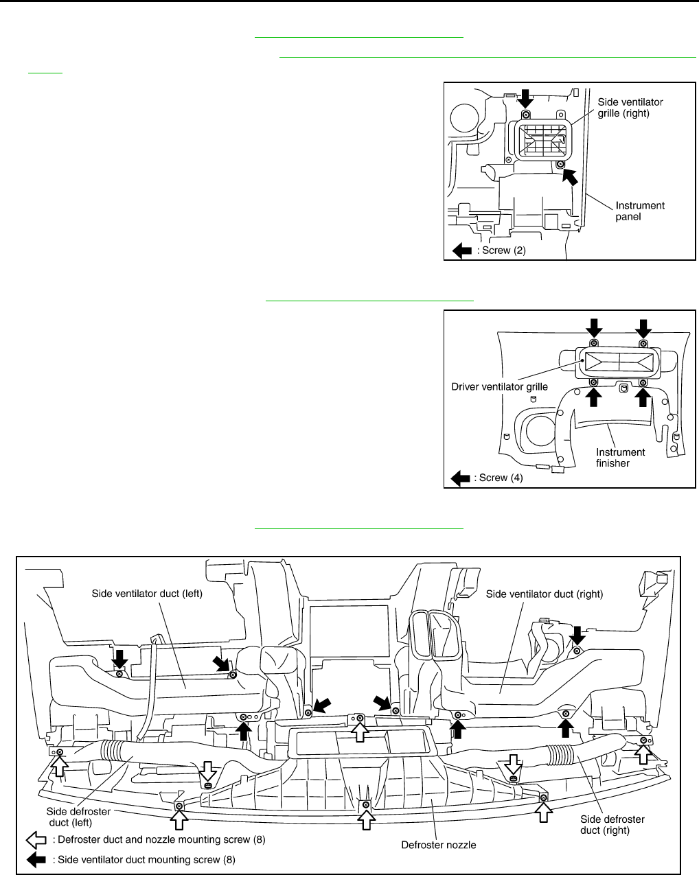
Removal of Side Ventilator Grille
1. Remove instrument panel. Refer to IP-11, "Removal and Installation" .
2. Remove side ventilator ducts. Refer to MTC-34, "Removal of Defroster Nozzle, Duct and Side Ventilator
Duct" .
3. Remove mounting screws, and then remove side ventilator
grille.
Removal of Driver Ventilator Grille
1. Remove instrument finisher. Refer to IP-11, "Removal and Installation" .
2. Remove mounting screws, and then remove driver ventilator
grille.
Removal of Defroster Nozzle, Duct and Side Ventilator Duct
1. Remove instrument panel. Refer to IP-11, "Removal and Installation" .
2. Remove mounting screws, and then remove side defroster ducts with defroster nozzle.
3. Remove mounting screws, and then remove side ventilator ducts.
RJIA2408E
RJIA2409E
RJIA2410E
DUCTS AND GRILLES
MTC-35
C
D
E
F
G
H
I
K
L
M
A
B
MTC
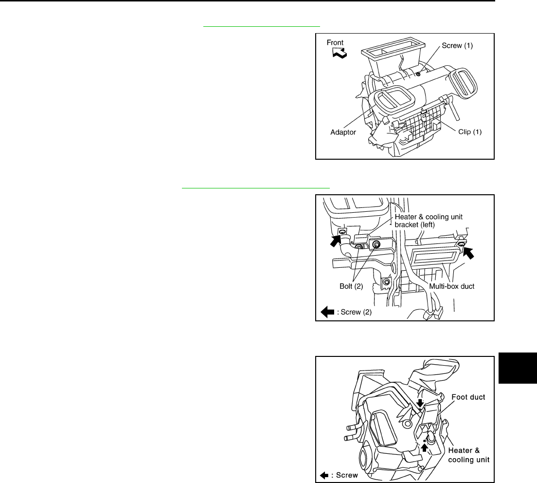
Removal of Adaptor
1. Remove heater (& cooling) unit. Refer toMTC-27, "HEATER UNIT" .
2. Remove mounting screw and clip.
3. Slide adaptor toward vehicle front, and then remove adaptor.
Removal of Multi-box Duct
1. Remove instrument panel. Refer to IP-11, "Removal and Installation" .
2. Remove mounting screws, and then disconnect multi-box duct
from heater (& cooling) unit.
3. Remove mounting bolts, and then remove heater (& cooling)
unit bracket.
4. Remove multi-box duct from left side.
Removal of Foot Duct
1. Remove multi-box duct.
2. Remove mounting screws, and then remove foot duct.
RJIA2411E
RJIA2412E
RJIA0069E
MTC-36
DUCTS AND GRILLES
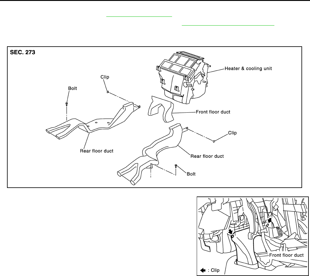
Removal of Floor Duct
1. Remove the front seats. Refer to SE-24, "FRONT SEAT" .
2. Remove multi-box (Instrument center lower panel). Refer to IP-11, "Removal and Installation" .
3. Peel back the floor trim to a point where the floor duct is visible.
4. Remove mounting bolts and clips, then remove rear floor duct.
5. Remove mounting clips, and then remove front floor duct.
INSTALLATION
Installation is basically the reverse order of removal.
RJIA0071E
RJIA0070E
