Nokia Bell 7577WPONAPE WPON User Manual WPON Product Overview
Nokia Shanghai Bell Co. Ltd. WPON WPON Product Overview
UserManual.wiki
>
Nokia Bell
>
7577WPONAPE User Manual
User Manual
Navigation menu
Upload a User Manual
Namespaces
Wiki Guide
HTML
PDF
Info
Views
User Manual
Discussion / Help
Navigation

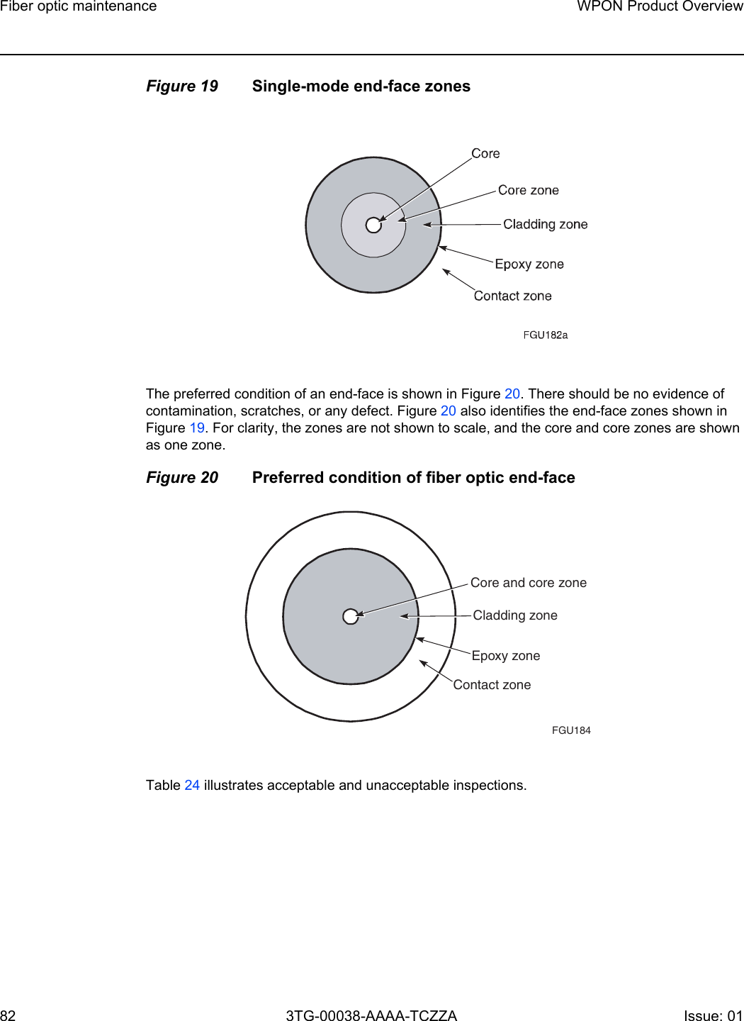
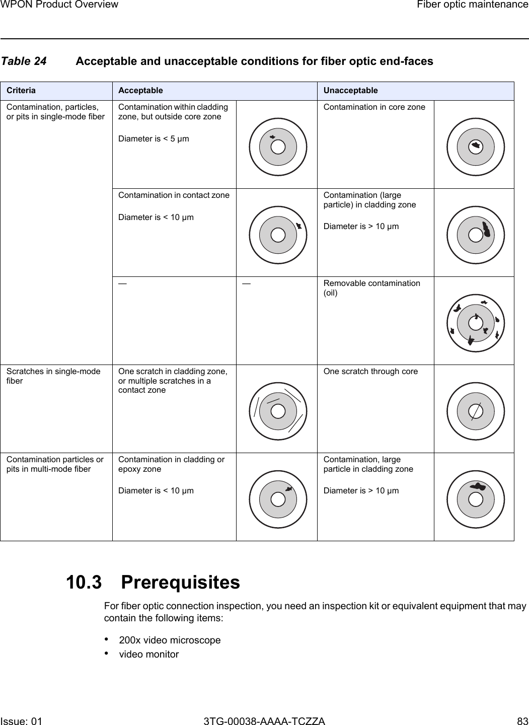
![WPON Product Overview AP unit data sheetIssue: 01 3TG-00038-AAAA-TCZZA 57 Table 8 AP physical specificationsTable 9 lists power consumption specifications for the APTable 9 AP power consumption specificationsTable 10 lists the environmental requirements for the AP.Table 10 AP environmental requirements6.7 AP wireless specificationsTable 11 lists the wireless specifications for the AP.Dimensions SpecificationsHeight 25.2 cmWidth 16.6 cmDepth 8.0 cmWeight [within ± 0.5 lb (0.23 kg)] 1650 gAP Maximum power (not to exceed)Condition Minimum powerConditionWall-mount 27 W Maximum traffic load 17 W No traffic loadPole-mount 27 W Maximum traffic load 17 W No traffic loadExtension 19 W Maximum traffic load 16 W No traffic loadMounting methodTemperature range and humidity AltitudePole or on an outside wallOperating:-22°F to 131°F (-30°C to 55°C) ambient temperature5% to 85% relative humidity, non-condensingMaximum operating altitude is 10 000 ft (3048 m) above mean sea levelStorage:–40°F to 140°F (–40° to 60°C) 5% to 93% relative humidity, non-condensingMaximum non-operating altitude is 40 000 ft (12 192 m) above mean sea level](https://usermanual.wiki/Nokia-Bell/7577WPONAPE/User-Guide-3956497-Page-57.png)
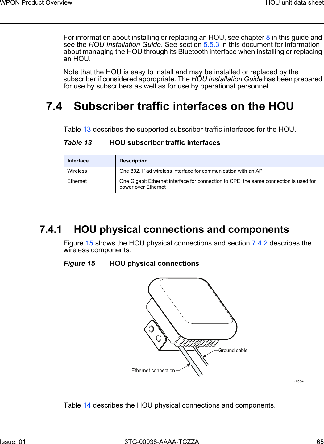
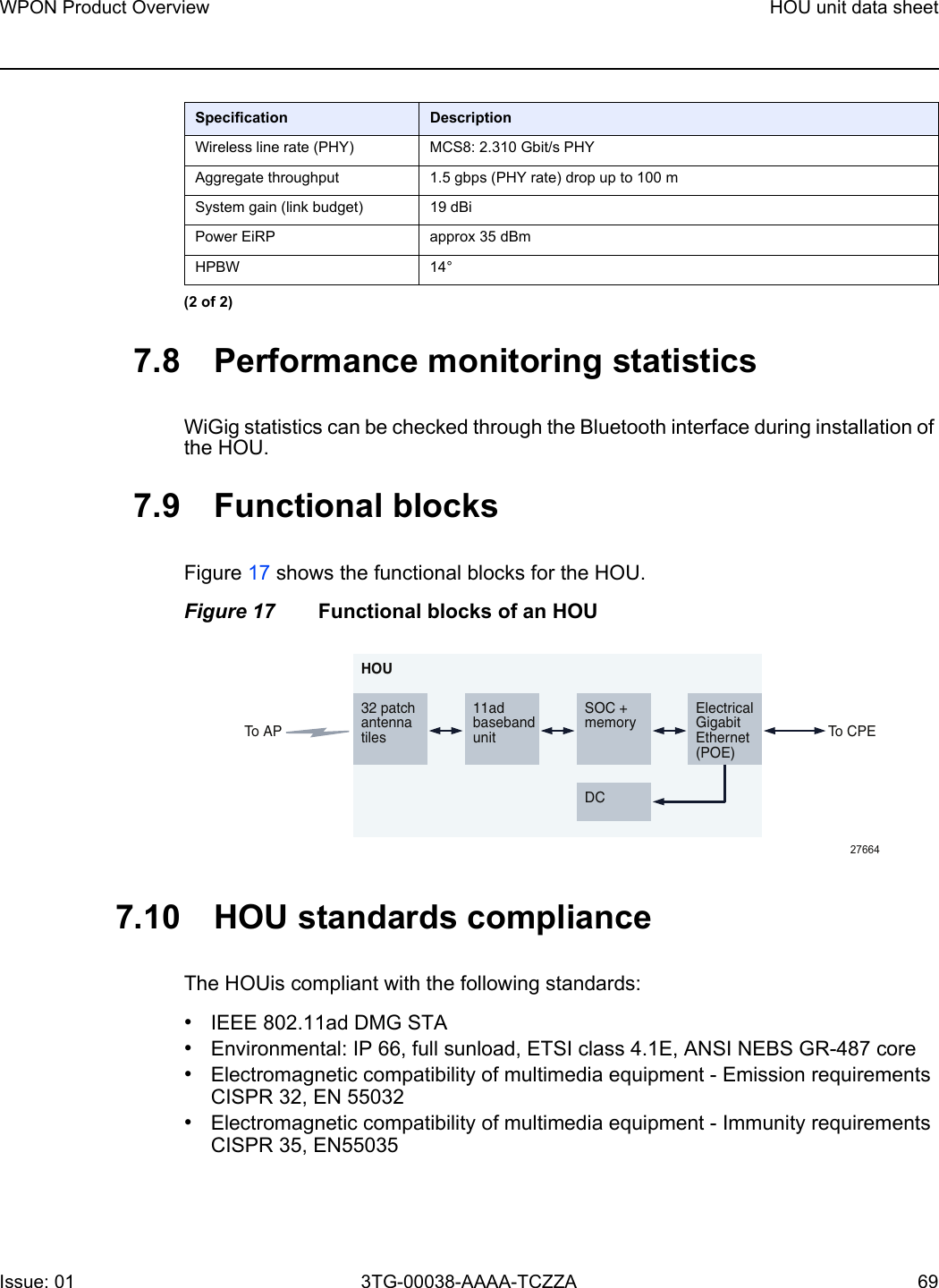
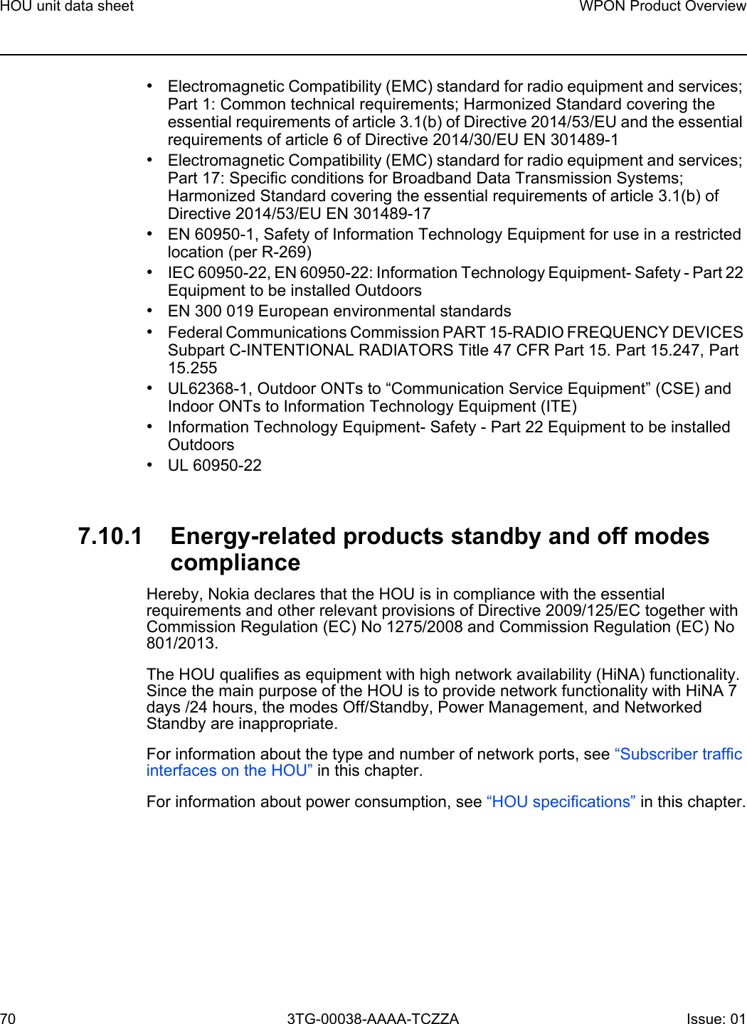
![HOU unit data sheet68WPON Product Overview3TG-00038-AAAA-TCZZA Issue: 01 Table 17 lists power consumption specifications for the HOU.Table 17 HOU power consumption specificationsTable 18 lists the environmental requirements for the HOU.Table 18 HOU environmental requirements7.7 HOU wireless specificationsTable 19 lists the wireless specifications for the HOU.Table 19 Wireless specifications for the HOUWeight [within ± 0.5 lb (0.23 kg)] 800 gMaximum power (not to exceed)Condition Minimum powerCondition16 W Maximum traffic load 13 W No traffic loadMounting methodTemperature range and humidity AltitudeOn an outside wallOperating:-22°F to 131°F (-30°C to 55°C) ambient temperature5% to 85% relative humidity, non-condensingMaximum operating altitude is 10 000 ft (3048 m) above mean sea levelStorage:–40°F to 140°F (–40° to 60°C) 5% to 93% relative humidity, non-condensingMaximum non-operating altitude is 40 000 ft (12 192 m) above mean sea level Dimensions Specifications(2 of 2)Specification DescriptionBase standard 802.11adDrop function 180° field of view thanks to multiple steerable beamforming high-gain patch antenna arraysFrequency and duplexing 60GHz / TDDChannels #2, #3 (center frequencies 60.48, 62.64 GHz) Channel width 2.16GHzModulation and coding Up to MCS8 (QPSK)(1 of 2)](https://usermanual.wiki/Nokia-Bell/7577WPONAPE/User-Guide-3956497-Page-68.png)