Nokia Bell 7577WPONAPE WPON User Manual WPON Product Overview
Nokia Shanghai Bell Co. Ltd. WPON WPON Product Overview
User Manual

Nokia — Proprietary and confidential
Use pursuant to applicable agreements
WPON AP-Ext User Manual
WPON Product Overview
3TG-00038-AAAA-TCZZA
Issue: 01
June 2018
WPON Product Overview

2
WPON Product Overview
3TG-00038-AAAA-TCZZA Issue: 01
Nokia is a registered trademark of Nokia Corporation. Other products and company
names mentioned herein may be trademarks or tradenames of their respective
owners.
The information presented is subject to change without notice. No responsibility is
assumed for inaccuracies contained herein.
© 2018 Nokia.
Contains proprietary/trade secret information which is the property of Nokia and must
not be made available to, or copied or used by anyone outside Nokia without its
written authorization. Not to be used or disclosed except in accordance with
applicable agreements.

WPON Product Overview Preface
Issue: 01 3TG-00038-AAAA-TCZZA 3
1Preface
This preface provides general information about the documentation for the Nokia
WPON solution.
1.1 Scope
The documentation for the WPON solution provides information about safety,
features and functionality, ordering, hardware installation and maintenance, and
software installation procedures for the products in the current release of the WPON
solution. The documentation for the WPON solution provides some information
about configuring products in the WPON solution.
1.2 Audience
The documentation for the WPON solution is intended for planners, administrators,
operators, and maintenance personnel involved in installing, upgrading, or
maintaining the products that are part of the WPON solution.
1.3 Required knowledge
The reader must be familiar with general telecommunications principles.
1.4 Acronyms and initialisms
Expansions and optional descriptions of most acronyms and initialisms used in this
document are provided in the glossary that is in this document.
1.5 Assistance and ordering phone numbers
Nokia provides global technical support through regional call centers. Phone
numbers for the regional call centers are available at the following URL:
http://support.alcatel-lucent.com.
For ordering information, contact your Nokia sales representative.
Note — The HOU installation guide that is in the document set
for the WPON solution has been prepared for use by
subscribers if it considered appropriate for them, rather than
operational personnel, to install or replace an HOU. The HOU
installation guide can be used by operational personnel as well.

Preface
4
WPON Product Overview
3TG-00038-AAAA-TCZZA Issue: 01
1.6 Nokia quality processes
Nokia’s WPON quality practices are in compliance with TL 9000 requirements.These
requirements are documented in the Fixed Networks Quality Manual
3FQ-30146-6000-QRZZA. The quality practices adequately ensure that technical
requirements and customer end-point requirements are met. The customer or its
representatives may be allowed to perform on-site quality surveillance audits, as
agreed upon during contract negotiations
1.7 Safety information
For safety information, see the appropriate safety guideline chapters.
1.8 Documents
Documents are available from Nokia using ALED or OLCS.
Procedure 1 To download a ZIP file package of the customer documentation
1Navigate to http://support.alcatel-lucent.com and enter your user name and password. If you
are a new user and require access to this service, please contact your Nokia sales
representative.
2From the Technical Content for drop-down menu, choose the product.
3Click on Downloads: Electronic Delivery.
4Choose Documentation from the drop-down menu and click Next.
5Select the image from the drop-down menu and click Next.
6Follow the on-screen directions to download the file.
WPON Product Overview Preface
Issue: 01 3TG-00038-AAAA-TCZZA 5
Procedure 2 To access individual documents
Individual PDFs of customer documents are also accessible through the Nokia Customer Support
website.
1Navigate to http://support.alcatel-lucent.com and enter your user name and password. If you
are a new user and require access to this service, please contact your Nokia sales
representative.
2From the Technical Content for drop-down menu, choose the product.
3Click on Manuals and Guides to display a list of customer documents by title and part
number. You can filter this list using the Release drop-down menu.
4Click on the PDF to open or save the file.
1.9 Special information
The following are examples of how special information is presented in this document.
Danger — Danger indicates that the described activity or
situation may result in serious personal injury or death; for
example, high voltage or electric shock hazards.
Warning — Warning indicates that the described activity or
situation may, or will, cause equipment damage or serious
performance problems.
Caution — Caution indicates that the described activity or
situation may, or will, cause service interruption.
Note — A note provides information that is, or may be, of
special interest.

Preface
6
WPON Product Overview
3TG-00038-AAAA-TCZZA Issue: 01
1.9.1 Steps with options or substeps
When there are options in a step, they are identified by letters. When there are
required substeps in a step, they are identified by roman numerals.
Procedure 3 Example of options in a step
At step 1, you must choose option a or b.
1This step offers two options. You must choose one of the following:
aThis is one option.
bThis is another option.
2You must perform this step.
Procedure 4 Example of required substeps in a step
At step 1, you must perform a series of substeps within the step.
1This step has a series of substeps that you must perform to complete the step. You must
perform the following substeps:
iThis is the first substep.
ii This is the second substep.
iii This is the third substep.
2 You must perform this step.
1.10 Multiple PDF document search
You can use Adobe Reader Release 6.0 and later to search multiple PDF files for a
common term. Adobe Reader displays the results in a single display panel. The
results are grouped by PDF file, and you can expand the entry for each file.
Note — The PDF files in which you search must be in the same
folder.

WPON Product Overview Preface
Issue: 01 3TG-00038-AAAA-TCZZA 7
Procedure 5 To search multiple PDF files for a common term
1Open Adobe Acrobat Reader.
2Choose Edit→Search from the Acrobat Reader main menu. The Search PDF panel appears.
3Enter the search criteria.
4Click on the All PDF Documents In radio button.
5Select the folder in which to search using the drop-down menu.
6Click on the Search button.
Acrobat Reader displays the search results. You can expand the entries for each document
by clicking on the + symbol.

Preface
8
WPON Product Overview
3TG-00038-AAAA-TCZZA Issue: 01

WPON Product Overview
Issue: 01 3TG-00038-AAAA-TCZZA 9
Table of contents
1 Preface.............................................................................................3
1.1 Scope ..........................................................................................................3
1.2 Audience......................................................................................................3
1.3 Required knowledge....................................................................................3
1.4 Acronyms and initialisms .............................................................................3
1.5 Assistance and ordering phone numbers ....................................................3
1.6 Nokia quality processes...............................................................................4
1.7 Safety information........................................................................................4
1.8 Documents ..................................................................................................4
1.9 Special information ......................................................................................5
1.9.1 Steps with options or substeps....................................................................6
1.10 Multiple PDF document search ...................................................................6
2 ETSI environmental and CRoHS guidelines...............................17
2.1 Environmental labels .................................................................................17
2.1.1 Overview....................................................................................................17
2.1.2 Environmental related labels .....................................................................17
2.1.2.1 Products below Maximum Concentration Value (MCV) label....................17
2.1.2.2 Products containing hazardous substances above Maximum
Concentration Value (MCV) label ..............................................................18
2.2 Hazardous Substances Table (HST).........................................................19
2.3 Other environmental requirements ............................................................20
2.3.1 Environmental requirements......................................................................20
2.3.2 Storage ......................................................................................................20
2.3.3 Transportation ...........................................................................................20
2.3.4 Stationary use............................................................................................20
2.3.5 Thermal limitations ....................................................................................20
2.3.6 Material content compliance......................................................................21
2.3.7 End-of-life collection and treatment ...........................................................21
3 ETSI safety guidelines..................................................................23
3.1 Safety instructions .....................................................................................23
3.1.1 Safety instruction boxes ............................................................................23
3.1.2 Safety-related labels..................................................................................24
3.2 Safety standards compliance ....................................................................24
3.2.1 EMC compliance .......................................................................................25
3.2.2 Equipment safety standard compliance.....................................................25
3.2.3 Environmental standard compliance .........................................................25
3.2.4 Laser product standard compliance ..........................................................25
3.3 Electrical safety guidelines ........................................................................26
3.3.1 Power supplies ..........................................................................................26
3.3.2 Cabling ......................................................................................................26
3.3.3 Protective earth .........................................................................................26
3.4 ESD safety guidelines ...............................................................................27
3.5 Environmental requirements......................................................................27

10
WPON Product Overview
3TG-00038-AAAA-TCZZA Issue: 01
4 ANSI safety guidelines .................................................................29
4.1 Safety instructions .....................................................................................29
4.1.1 Safety instruction boxes in customer documentation ................................29
4.1.2 Safety-related labels..................................................................................30
4.2 Safety standards compliance ....................................................................31
4.2.1 EMC, EMI, and ESD compliance...............................................................31
4.2.2 Equipment safety standard compliance.....................................................32
4.3 Electrical safety guidelines ........................................................................32
4.3.1 Power supplies ..........................................................................................32
4.3.2 Cabling ......................................................................................................33
4.3.3 Protective earth .........................................................................................33
4.4 ESD safety guidelines ...............................................................................33
4.5 Environmental requirements......................................................................33
5 WPON solution overview .............................................................35
5.1 WPON solution ..........................................................................................35
5.1.1 APs ............................................................................................................37
5.1.1.1 Head AP ....................................................................................................38
5.1.1.2 Relay AP....................................................................................................38
5.1.1.3 Extension AP .............................................................................................38
5.1.2 HOUs.........................................................................................................39
5.1.3 APs and HOUs in WPONs ........................................................................39
5.2 WPON topologies ......................................................................................39
5.2.1 Basic WPON topology ...............................................................................39
5.2.2 Wireless daisy chain topology ...................................................................40
5.3 WPON architecture....................................................................................42
5.3.1 Underlay network.......................................................................................42
5.3.2 Overlay network.........................................................................................43
5.4 WPON services .........................................................................................43
5.5 WPON management .................................................................................45
5.5.1 WPON management through the WPON manager ..................................45
5.5.2 WPON management through the Nokia Altiplano .....................................46
5.5.3 WPON management through Bluetooth ...................................................47
5.6 WPON planning considerations.................................................................48
5.7 Compatible CPE ........................................................................................48
6 AP unit data sheet ........................................................................49
6.1 AP part numbers and identification............................................................49
6.2 AP general description ..............................................................................51
6.3 AP software and installation feature support .............................................52
6.4 Subscriber traffic interfaces on the AP ......................................................52
6.4.1 AP physical connections and components ................................................53
6.4.2 AP wireless components ...........................................................................55
6.5 AP LED information ...................................................................................55
6.6 AP specifications .......................................................................................56
6.7 AP wireless specifications .........................................................................57
6.8 Performance monitoring statistics .............................................................58
6.9 Functional blocks.......................................................................................58
6.10 AP standards compliance..........................................................................59
6.10.1 Energy-related products standby and off modes compliance....................60

WPON Product Overview
Issue: 01 3TG-00038-AAAA-TCZZA 11
6.10.2 AP compliance statement..........................................................................61
7 HOU unit data sheet .....................................................................63
7.1 HOU part numbers and identification ........................................................63
7.2 HOU general description ...........................................................................64
7.3 HOU software and installation feature support..........................................64
7.4 Subscriber traffic interfaces on the HOU ...................................................65
7.4.1 HOU physical connections and components.............................................65
7.4.2 HOU wireless components ........................................................................66
7.5 HOU LED information................................................................................66
7.6 HOU specifications ....................................................................................67
7.7 HOU wireless specifications ......................................................................68
7.8 Performance monitoring statistics .............................................................69
7.9 Functional blocks.......................................................................................69
7.10 HOU standards compliance.......................................................................69
7.10.1 Energy-related products standby and off modes compliance....................70
7.10.2 HOU compliance statement.......................................................................71
8 Installing or replacing APs and HOUs ........................................73
8.1 Installation scenarios for APs and HOUs ..................................................73
8.2 Replacement scenarios for APs and HOUs ..............................................73
8.3 AP installation and replacement ................................................................73
8.4 HOU installation and replacement.............................................................74
8.4.1 HOU pre-installation tasks.........................................................................74
8.4.2 HOU pre-replacement tasks ......................................................................75
9 Configure an AP or HOU ..............................................................77
9.1 AP configuration ........................................................................................77
9.1.1 Local configuration of an AP......................................................................77
9.2 HOU configuration .....................................................................................77
9.2.1 Local configuration of an HOU ..................................................................78
10 Fiber optic maintenance ..............................................................79
10.1 Purpose .....................................................................................................79
10.2 General......................................................................................................79
10.2.1 Handling considerations ............................................................................79
10.2.2 Fiber optic jumper cable care ....................................................................80
10.2.3 Acceptance criteria for fiber optic device inspections................................80
10.2.4 Acceptance criteria ....................................................................................81
10.3 Prerequisites..............................................................................................83
10.4 Parts list.....................................................................................................84
10.5 Recommended tools..................................................................................84
10.6 Procedure ..................................................................................................85
11 Glossary ........................................................................................89

12
WPON Product Overview
3TG-00038-AAAA-TCZZA Issue: 01

WPON Product Overview
Issue: 01 3TG-00038-AAAA-TCZZA 13
List of figures
2 ETSI environmental and CRoHS guidelines...............................17
Figure 1 Products below MCV value label...............................................................18
Figure 2 Products above MCV value label ..............................................................19
Figure 3 Recycling/take back/disposal of product symbol .......................................21
4 ANSI safety guidelines .................................................................29
Figure 4 Sample safety label ...................................................................................31
5 WPON solution overview .............................................................35
Figure 5 High-level representation of the WPON solution .......................................36
Figure 6 WPON example with a 7360 ISAM............................................................37
Figure 7 Example of an AP pair...............................................................................38
Figure 8 Example of a linear daisy chain topology ..................................................41
Figure 9 Example of a daisy chain topology that has an AP pair ............................42
Figure 10 WPON service support with an ISAM........................................................44
Figure 11 WPON service independent an ISAM .......................................................44
6 AP unit data sheet ........................................................................49
Figure 12 AP physical connections............................................................................54
Figure 13 AP LED location ........................................................................................56
Figure 14 Functional blocks of an AP ........................................................................59
7 HOU unit data sheet .....................................................................63
Figure 15 HOU physical connections ........................................................................65
Figure 16 HOU LED location .....................................................................................67
Figure 17 Functional blocks of an HOU.....................................................................69
10 Fiber optic maintenance ..............................................................79
Figure 18 Parts of a fiber optic cable .........................................................................80
Figure 19 Single-mode end-face zones.....................................................................82
Figure 20 Preferred condition of fiber optic end-face.................................................82

14
WPON Product Overview
3TG-00038-AAAA-TCZZA Issue: 01

WPON Product Overview
Issue: 01 3TG-00038-AAAA-TCZZA 15
List of tables
3 ETSI safety guidelines..................................................................23
Table 1 Safety labels..............................................................................................24
4 ANSI safety guidelines .................................................................29
Table 2 Safety labels..............................................................................................30
6 AP unit data sheet ........................................................................49
Table 3 AP part numbers and descriptions ............................................................50
Table 4 AP accessories..........................................................................................51
Table 5 AP subscriber traffic interfaces..................................................................53
Table 6 AP physical connections and components ................................................54
Table 7 AP LED behavior description.....................................................................56
Table 8 AP physical specifications .........................................................................57
Table 9 AP power consumption specifications .......................................................57
Table 10 AP environmental requirements ................................................................57
Table 11 Wireless specifications for the AP .............................................................58
7 HOU unit data sheet .....................................................................63
Table 12 HOU part numbers and descriptions .........................................................63
Table 13 HOU subscriber traffic interfaces...............................................................65
Table 14 HOU physical connections and components.............................................66
Table 15 HOU LED behavior description .................................................................67
Table 16 HOU physical specifications ......................................................................67
Table 17 HOU power consumption specifications....................................................68
Table 18 HOU environmental requirements .............................................................68
Table 19 Wireless specifications for the HOU ..........................................................68
8 Installing or replacing APs and HOUs ........................................73
Table 20 HOU installation and replacement actions ................................................74
Table 21 Pre-installation tasks for the HOU .............................................................75
Table 22 Pre-replacement tasks for the HOU ..........................................................75
10 Fiber optic maintenance ..............................................................79
Table 23 Single-mode end-face inspection acceptance criteria ...............................81
Table 24 Acceptable and unacceptable conditions for fiber optic end-faces............83

16
WPON Product Overview
3TG-00038-AAAA-TCZZA Issue: 01

WPON Product Overview ETSI environmental and CRoHS guidelines
Issue: 01 3TG-00038-AAAA-TCZZA 17
2 ETSI environmental and CRoHS
guidelines
This chapter provides information about the ETSI environmental China Restriction of
Hazardous Substances (CRoHS) regulations that govern the installation and
operation of AP and HOU equipment. This chapter also includes environmental
operation parameters of general interest.
2.1 Environmental labels
This section describes the environmental instructions that are provided with the
customer documentation, equipment, and location where the equipment resides.
2.1.1 Overview
CRoHS is applicable to Electronic Information Products (EIP) manufactured or sold
and imported in the territory of the mainland of the People’s Republic of China. EIP
refers to products and their accessories manufactured by using electronic
information technology, including electronic communications products and such
subcomponents as batteries and cables.
2.1.2 Environmental related labels
Environmental labels are located on appropriate equipment. The following are
sample labels.
2.1.2.1 Products below Maximum Concentration Value
(MCV) label
Figure 1 shows the label that indicates a product is below the maximum
concentration value, as defined by standard SJ/T11363-2006 (Requirements for
Concentration Limits for Certain Hazardous Substances in Electronic Information
Products). Products with this label are recyclable. The label may be found in this
documentation or on the product.

ETSI environmental and CRoHS guidelines
18
WPON Product Overview
3TG-00038-AAAA-TCZZA Issue: 01
Figure 1 Products below MCV value label
2.1.2.2 Products containing hazardous substances above
Maximum Concentration Value (MCV) label
Figure 2 shows the label that indicates a product is above the maximum
concentration value, as defined by standard SJ/T11363-2006 (Requirements for
Concentration Limits for Certain Hazardous Substances in Electronic Information
Products). The number contained inside the label indicates the Environment-Friendly
User Period (EFUP) value. The label may be found in this documentation or on the
product.
18986

WPON Product Overview ETSI environmental and CRoHS guidelines
Issue: 01 3TG-00038-AAAA-TCZZA 19
Figure 2 Products above MCV value label
Together with major international telecommunications equipment companies, Nokia
has determined it is appropriate to use an EFUP of 50 years for network
infrastructure equipment and an EFUP of 20 years for handsets and accessories.
These values are based on manufacturers' extensive practical experience of the
design, manufacturing, maintenance, usage conditions, operating environments,
and physical condition of infrastructure and handsets after years of service. The
values reflect minimum values and refer to products operated according to the
intended use conditions. See “Hazardous Substances Table (HST)” for more
information.
2.2 Hazardous Substances Table (HST)
This section describes the compliance of the AP and HOU equipment to the CRoHS
standard when the product and subassemblies contain hazardous substances
beyond the MCV value. This information is found in this user documentation where
part numbers for the product and subassemblies are listed. It may be referenced in
other documentation that describes the AP or HOU equipment.
In accordance with the People’s Republic of China Electronic Industry Standard
Marking for the Control of Pollution Caused by Electronic Information Products
(SJ/T11364-2006), customers may access the Nokia Hazardous Substance Table,
in Chinese, from the following location:
•http://www.alcatel-sbell.com.cn/wwwroot/images/upload/private/1/media/ChinaRo
HS.pdf
18985

ETSI environmental and CRoHS guidelines
20
WPON Product Overview
3TG-00038-AAAA-TCZZA Issue: 01
2.3 Other environmental requirements
Observe the following environmental requirements when handling AP or HOU
equipment.
2.3.1 Environmental requirements
See chapter 6 in this guide for more information about temperature ranges for the AP
equipment and other AP specifications.
See chapter 7 in this guide for more information about temperature ranges for the
HOU equipment and other HOU specifications.
2.3.2 Storage
According to ETS 300-019-1-1 - Class 1.1, storage of AP and HOU equipment must
be in Class 1.1, weather-protected, temperature-controlled locations.
2.3.3 Transportation
According to EN 300-019-1-2 - Class 2.3, transportation of AP and HOU equipment
must be in packed, public transportation with no rain on packing allowed.
2.3.4 Stationary use
According to EN 300-019-1-3 - Class 3.1/3.2/3.E, stationary use of AP and HOU
equipment must be in a temperature-controlled location, with no rain allowed, and
with no condensation allowed.
2.3.5 Thermal limitations
The thermal limitations for the AP and HOU equipment are:
•operating temperature (ambient): –30°C to 55°C (–22°F to 131°F)
•operating relative humidity: 5% to 85%
•short-term relative humidity: 5% to 95%, but not to exceed 0.024 kg of water/kg
WPON Product Overview ETSI environmental and CRoHS guidelines
Issue: 01 3TG-00038-AAAA-TCZZA 21
2.3.6 Material content compliance
European Union (EU) Directive 2002/95/EC, “Restriction of the use of certain
Hazardous Substances” (RoHS), restricts the use of lead, mercury, cadmium,
hexavalent chromium, and certain flame retardants in electrical and electronic
equipment. This Directive applies to electrical and electronic products placed on the
EU market after 1 July 2006, with various exemptions, including an exemption for
lead solder in network infrastructure equipment. Nokia products shipped to the EU
after 1 July 2006 comply with the EU RoHS Directive.
Nokia has implemented a material/substance content management process. The
process is described in: Nokia process for ensuring RoHS Compliance
(1AA002660031ASZZA). This ensures compliance with the European Union
Directive 2011/65/EU on the Restriction of the Use of Certain Hazardous Substances
in Electrical and Electronic Equipment (RoHS2). With the process equipment is
assessed in accordance with the Harmonised Standard EN50581:2012 (CENELEC)
on Technical documentation for the assessment of electrical and electronic products
with respect to the restriction of hazardous substances.
2.3.7 End-of-life collection and treatment
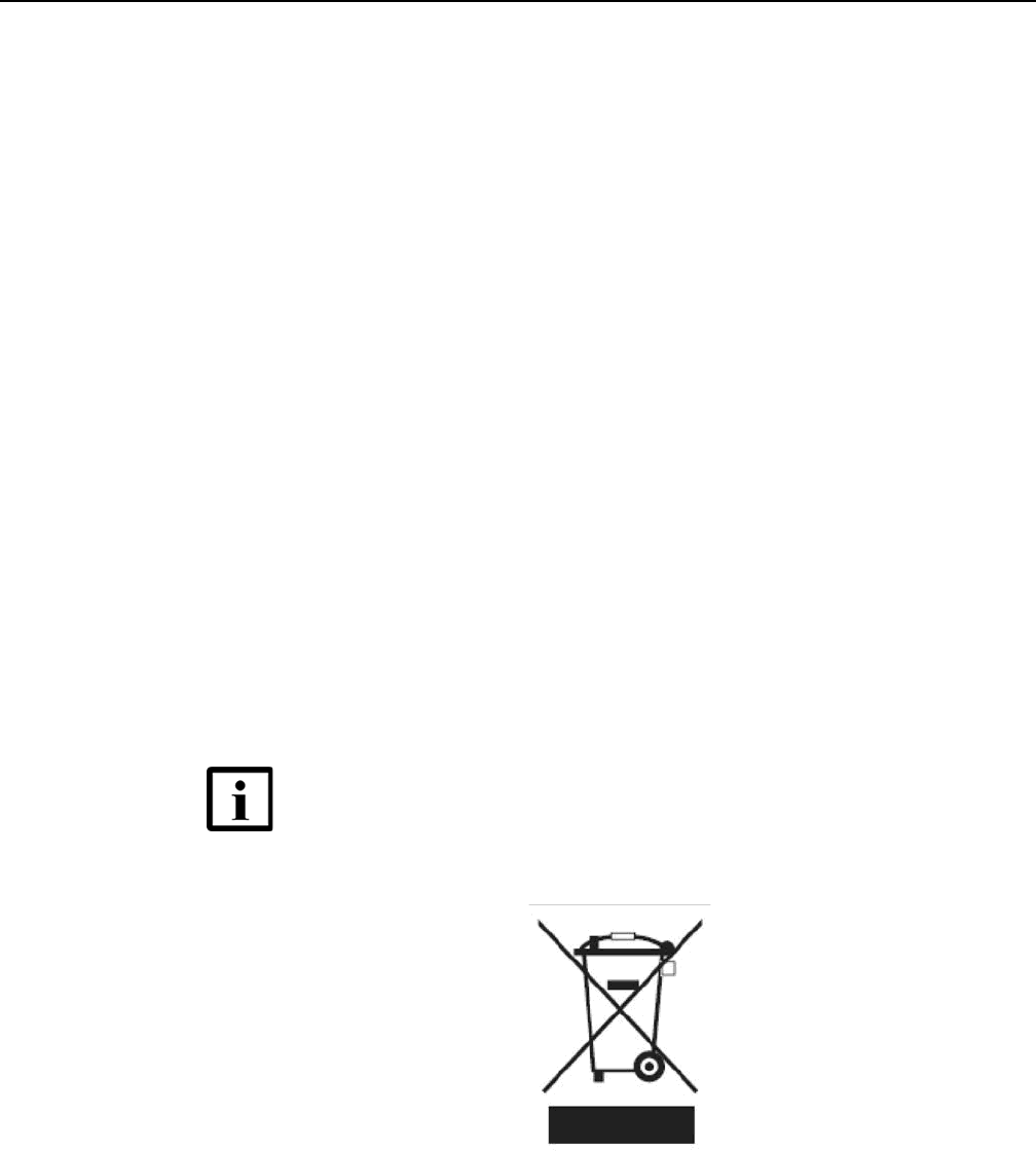
Electronic products bearing or referencing the symbol shown in Figure 3, when put
on the market within the European Union (EU), shall be collected and treated at the
end of their useful life, in compliance with applicable EU and local legislation. They
shall not be disposed of as part of unsorted municipal waste. Due to materials that
may be contained in the product, such as heavy metals or batteries, the environment
and human health may be negatively impacted as a result of inappropriate disposal.
Figure 3 Recycling/take back/disposal of product symbol
Note — In the European Union, a solid bar under the symbol for
a crossed-out wheeled bin indicates that the product was put on
the market after 13 August 2005.

ETSI environmental and CRoHS guidelines
22
WPON Product Overview
3TG-00038-AAAA-TCZZA Issue: 01
At the end of its life, AP and HOU equipment is subject to the applicable local
legislations that implement the European Directive 2012/19EU on waste electrical
and electronic equipment (WEEE).
There can be different requirements for collection and treatment in different member
states of the European Union.
In compliance with legal requirements and contractual agreements, where
applicable, Nokia will offer to provide for the collection and treatment of Nokia
products bearing the logo shown in Figure 3 at the end of their useful life, or products
displaced by Nokia equipment offers. For information regarding take-back of
equipment by Nokia, or for more information regarding the requirements for
recycling/disposal of product, contact your Nokia account manager or Nokia take
back support at sustainability.global@nokia.com.
WPON Product Overview ETSI safety guidelines
Issue: 01 3TG-00038-AAAA-TCZZA 23
3 ETSI safety guidelines
This chapter provides information about the mandatory regulations that govern the
installation and operation of AP and HOU equipment in the ETSI market.
3.1 Safety instructions
This section describes the safety instructions that are provided in the customer
documentation and on the AP and HOU equipment.
3.1.1 Safety instruction boxes
The safety instruction boxes are provided in the AP and HOU customer
documentation. Observe the instructions to meet safety requirements.
The following is an example of the Danger box.
The Danger box indicates that the described activity or situation may pose a threat
to personal safety. It calls attention to a situation or procedure which, if not correctly
performed or adhered to, may result in death or serious physical harm.
Do not proceed beyond a Danger box until the indicated conditions are fully
understood and met.
The following is an example of the Warning box.
The Warning box indicates that the described activity or situation may, or will, cause
equipment damage, loss of data, or serious performance problems. It identifies a
possible equipment-damaging situation or provides essential information to avoid the
degradation of system operations or data.
Do not proceed beyond a warning until the indicated conditions are fully understood
and met.
Danger — Possibility of personal injury.
Warning 1 — Possibility of equipment damage.
Warning 2 — Possibility of data loss.
ETSI safety guidelines
24
WPON Product Overview
3TG-00038-AAAA-TCZZA Issue: 01
The following is an example of the Caution box.
The Caution box indicates that the described activity or situation may, or will, cause
service interruption.
Do not proceed beyond a caution until the indicated conditions are fully understood
and met.
The following is an example of the Note box.
The Note box provides information that assists the personnel working with AP or
HOU equipment. It does not provide safety-related instructions.
3.1.2 Safety-related labels
The AP and HOU equipment is labeled with the specific safety instructions and
compliance information that is related to a product, or product variant, of the
equipment. Observe the instructions on the safety labels.
Table 1 provides sample safety labels on AP and HOU equipment.
Table 1 Safety labels
3.2 Safety standards compliance
This section describes AP and HOU equipment compliance with the European safety
standards.
Caution 1 — Possibility of service interruption.
Caution 2 — Service interruption.
Note — Information of special interest.
Description Label text
ESD warning Caution: This assembly contains an electrostatic sensitive device.

WPON Product Overview ETSI safety guidelines
Issue: 01 3TG-00038-AAAA-TCZZA 25
3.2.1 EMC compliance
The AP and HOU equipment complies with the following EMC requirements:
•Electromagnetic compatibility of multimedia equipment - Emission requirements
CISPR 32, EN 55032
•Electromagnetic compatibility of multimedia equipment - Immunity requirements
CISPR 35, EN55035
•Electromagnetic Compatibility (EMC) standard for radio equipment and services;
Part 1: Common technical requirements; Harmonized Standard covering the
essential requirements of article 3.1(b) of Directive 2014/53/EU and the essential
requirements of article 6 of Directive 2014/30/EU EN 301489-1
•Electromagnetic Compatibility (EMC) standard for radio equipment and services;
Part 17: Specific conditions for Broadband Data Transmission Systems;
Harmonized Standard covering the essential requirements of article 3.1(b) of
Directive 2014/53/EU EN 301489-17
3.2.2 Equipment safety standard compliance
The AP and HOU equipment complies with the requirements of the following:
•EN 60950-1, Safety of Information Technology Equipment for use in a restricted
location (per R-269)
•IEC 60950-22, EN 60950-22: Information Technology Equipment- Safety - Part 22
Equipment to be installed Outdoors
3.2.3 Environmental standard compliance
The AP and HOU equipment complies with the EN 300 019 European environmental
standards.
3.2.4 Laser product standard compliance
The AP and HOU equipment is not a laser product.

ETSI safety guidelines
26
WPON Product Overview
3TG-00038-AAAA-TCZZA Issue: 01
3.3 Electrical safety guidelines
This section provides the electrical safety guidelines for the AP and HOU equipment.
3.3.1 Power supplies
The use of any non-Nokia approved power supplies or power adapters is not
supported or endorsed by Nokia. Such use will void any warranty or support contract
with Nokia. Such use greatly increases the danger of damage to equipment or
property.
3.3.2 Cabling
The following are the guidelines regarding cables used for the AP and HOU
equipment:
•All cables must be approved by the relevant national electrical code.
•Cables for connection to the AP equipment must be suitable for outdoor use.
•Cables for outdoor connection to the HOU equipment must be suitable for outdoor
use.
•The HOU equipment must be used with the cabling supplied with the equipment.
3.3.3 Protective earth
Earthing and bonding of the AP and HOU equipment must comply with the
requirements of local electrical codes.
Note 1 — The AP and HOU equipment complies with the U.S.
National Electrical Code. However, local electrical authorities
have jurisdiction when there are differences between the local
and U.S. standards.
Note 2 — The AP and HOU equipment complies with BS EN
61140.

WPON Product Overview ETSI safety guidelines
Issue: 01 3TG-00038-AAAA-TCZZA 27
3.4 ESD safety guidelines
The AP and HOU equipment is sensitive to ESD if opened. Operations personnel
must observe the following ESD instructions when they handle the AP or HOU
equipment.
Service personnel are not required to wear wrist straps when performing normal
installation or maintenance activities.
3.5 Environmental requirements
See chapter 6 in this guide for more information about temperature ranges for the AP
equipment and other AP specifications.
See chapter 7 in this guide for more information about temperature ranges for the
HOU equipment and other HOU specifications.
During operation in the supported temperature range, condensation inside the AP
and HOU equipment caused by humidity is not an issue because the AP and HOU
are sealed units.
Caution — This equipment is ESD sensitive if opened. Proper
ESD protections should be used if you open the AP or HOU.

ETSI safety guidelines
28
WPON Product Overview
3TG-00038-AAAA-TCZZA Issue: 01
WPON Product Overview ANSI safety guidelines
Issue: 01 3TG-00038-AAAA-TCZZA 29
4 ANSI safety guidelines
This chapter provides information about the mandatory regulations that govern the
installation and operation of the AP and HOU equipment in the North American or
ANSI market.
4.1 Safety instructions
This section describes the safety instructions that are provided in the customer
documentation and on the AP and HOU equipment.
4.1.1 Safety instruction boxes in customer
documentation
The safety instruction boxes are provided in the AP and HOU customer
documentation. Observe the instructions to meet safety requirements.
The following is an example of the Danger box.
The Danger box indicates that the described activity or situation may pose a threat
to personal safety. It calls attention to a situation or procedure which, if not correctly
performed or adhered to, may result in death or serious physical harm.
Do not proceed beyond a Danger box until the indicated conditions are fully
understood and met.
The following is an example of the Warning box.
The Warning box indicates that the described activity or situation may, or will, cause
equipment damage, loss of data, or serious performance problems. It identifies a
possible equipment-damaging situation or provides essential information to avoid the
degradation of system operations or data.
Do not proceed beyond a warning until the indicated conditions are fully understood
and met.
Danger — Possibility of personal injury.
Warning 1 — Possibility of equipment damage.
Warning 2 — Possibility of data loss.
ANSI safety guidelines
30
WPON Product Overview
3TG-00038-AAAA-TCZZA Issue: 01
The following is an example of the Caution box.
The Caution box indicates that the described activity or situation may, or will, cause
service interruption.
Do not proceed beyond a caution until the indicated conditions are fully understood
and met.
The following is an example of the Note box.
The Note box provides information that assists the personnel working with AP or
HOU equipment. It does not provide safety-related instructions.
4.1.2 Safety-related labels
The AP and HOU equipment is labeled with specific safety compliance information
and instructions that are related to a product, or product variant, of the equipment.
Observe the instructions on the safety labels.
Table 2 provides examples of the text in the various AP and HOU equipment safety
labels.
Table 2 Safety labels
Figure 4 shows a sample safety label.
Caution 1 — Possibility of service interruption.
Caution 2 — Service interruption.
Note — Information of special interest.
Description Label text
UL compliance ETL/cETL
UL50E compliance Type 3
ESD warning Caution: This assembly contains electrostatic sensitive device.
FCC standards compliance Tested to comply with FCC standards for home or office use.
Operation conditions This device complies with Part 15 of the FCC Rules. Operation is
subject to the following two conditions: (1) this device may not cause
harmful interference, and (2) this device must accept any interference
received, including interference that may cause undesired operation.
CE marking There are various CE symbols for CE compliance.
WPON Product Overview ANSI safety guidelines
Issue: 01 3TG-00038-AAAA-TCZZA 31
Figure 4 Sample safety label
4.2 Safety standards compliance
This section describes the AP and HOU equipment compliance with North American
safety standards.
4.2.1 EMC, EMI, and ESD compliance
The AP and HOU equipment complies with the following EMC, EMI, and ESD
requirements:
•Federal Communications Commission PART 15-RADIO FREQUENCY DEVICES
Subpart C-INTENTIONAL RADIATORS Title 47 CFR Part 15. Part 15.247, Part
15.255
This equipment has been tested and found to comply with the limits for a Class B
digital device, pursuant to Part 15 of the FCC Rules. These limits are designed to
provide reasonable protection against harmful interference in a residential
installation. This equipment generates, uses and can radiate radio frequency energy
and, if not installed and used in accordance with the instructions, may cause harmful
interference to radio communications.
18533
This device complies with Part 15 of the FCC Rules. Operation is subject
to the following two conditions: (1) this device may not cause harmful
interference, and (2) this device must accept any interference
received, including interference that may cause undesired operation.
This Class A digital apparatus complies with Canadian ICES-003. Cet appareil
numerique de la class A est conforme a la norme NMB-003 du Canada
Tested to Comply
with FCC Standards
FOR HOME OR OFFICE USE
COMMUNICATION SERVICE EQUIPMENT
US LISTED
27FY
Type 3R Enclosure - Rainproof
CAUTION
This Assembly Contains Electrostatic Sensitive Devices
c
®
Warning — Changes or modifications to this unit not expressly
approved by the party responsible for compliance could void
the user's authority to operate the equipment.

ANSI safety guidelines
32
WPON Product Overview
3TG-00038-AAAA-TCZZA Issue: 01
However, there is no guarantee that interference will not occur in a particular
installation. If this equipment does cause harmful interference to radio or television
reception, which can be determined by turning the equipment off and on, the user is
encouraged to try to correct the interference by one or more of the following
measures:
•Reorient or relocate the receiving antenna.
•Increase the separation between the equipment and receiver.
•Connect the equipment into an outlet on a circuit different from that to which the
receiver is needed.
•Consult the dealer or an experienced radio/TV technician for help.
4.2.2 Equipment safety standard compliance
The AP and HOU equipment complies with the requirements of:
•UL62368-1, Outdoor ONTs to “Communication Service Equipment” (CSE) and
Indoor ONTs to Information Technology Equipment (ITE)
•Information Technology Equipment- Safety - Part 22 Equipment to be installed
Outdoors
•UL 60950-22
4.3 Electrical safety guidelines
This section provides the electrical safety guidelines for the AP and HOU equipment.
4.3.1 Power supplies
The use of any non-Nokia approved power supplies or power adapters is not
supported or endorsed by Nokia. Such use will void any warranty or support contract
with Nokia. Such use greatly increases the danger of damage to equipment or
property.
Note — The AP and HOU equipment complies with the U.S.
National Electrical Code. However, local electrical authorities
have jurisdiction when there are differences between the local
and U.S. standards.

WPON Product Overview ANSI safety guidelines
Issue: 01 3TG-00038-AAAA-TCZZA 33
4.3.2 Cabling
The following are the guidelines regarding cables used for the AP and HOU
equipment:
•All cables must be approved by the relevant national electrical code.
•Cables for connection to the AP equipment must be suitable for outdoor use.
•Cables for outdoor connection to the HOU equipment must be suitable for outdoor
use.
•The HOU equipment must be used with the cabling supplied with the equipment.
4.3.3 Protective earth
Earthing and bonding of the AP and HOU equipment must comply with the
requirements of NEC article 250 or local electrical codes.
4.4 ESD safety guidelines
The AP and HOU equipment is sensitive to ESD if opened. Operations personnel
must observe the following ESD instructions when they handle the AP or HOU
equipment.
Service personnel are not required to wear wrist straps when performing normal
installation or maintenance activities.
4.5 Environmental requirements
See chapter 6 in this guide for more information about temperature ranges for the AP
equipment and other AP specifications.
See chapter 7 in this guide for more information about temperature ranges for the
HOU equipment and other HOU specifications.
During operation in the supported temperature range, condensation inside the AP
and HOU equipment caused by humidity is not an issue because the AP and HOU
are sealed units.
Caution — This equipment is ESD sensitive if opened. Proper
ESD protections should be used if you open the AP or HOU.

ANSI safety guidelines
34
WPON Product Overview
3TG-00038-AAAA-TCZZA Issue: 01

WPON Product Overview WPON solution overview
Issue: 01 3TG-00038-AAAA-TCZZA 35
5 WPON solution overview
5.1 WPON solution
5.2 WPON topologies
5.3 WPON architecture
5.4 WPON services
5.5 WPON management
5.6 WPON planning considerations
5.7 Compatible CPE
5.1 WPON solution
The Nokia Wireless PON solution is an ideal technology for fixed operators to use as
an alternative to a physical fiber drop. It provides a 60 GHz wireless drop for a PON
or P2P-based optic network so that fiber optic cables are not used for connection to
subscribers’ homes. The WPON solution can be deployed tactically to provide
ubiquitous coverage to service areas where fiber is impractical, or strategically for a
whole service area as a lower-cost alternative to Gigabit fiber to the home.
The WPON has an Access Point (AP) that physically connects to the PON or
P2P-based optic network. The AP uses wireless communication with up to eight
Home Outside Units (HOUs) per AP that provide Gigabit Ethernet connectivity to
CPE inside the subscriber homes.
Connectivity from the AP to the PON, or 1 Gigabit Ethernet or 10 Gigabit Ethernet
P2P-based optic network, is done through an SFP module that can be installed in the
SFP cage of the AP. The SFP module can be an SFP ONT or a P2P optical Ethernet
uplink SFP.
The WPON solution delivers ultra broadband access over short distances with
limited interference between systems because of narrow beams and inherent
propagation limitations of this standard.
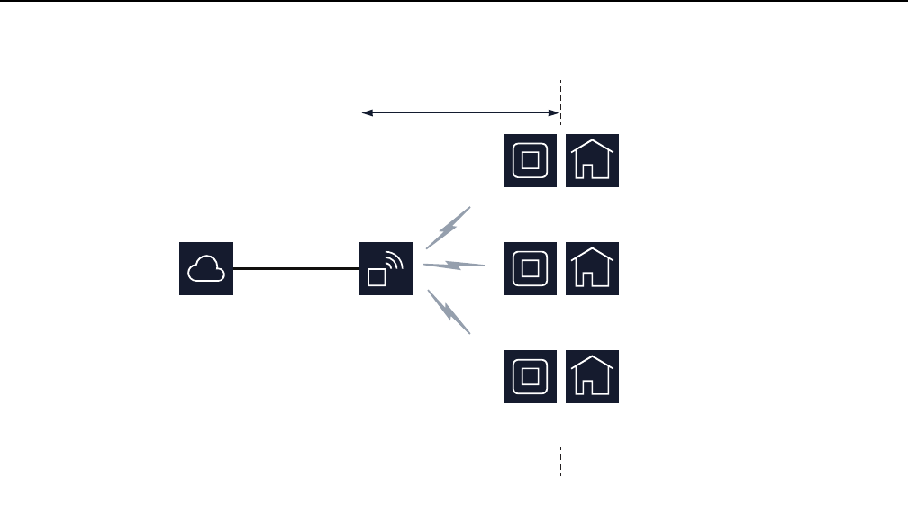
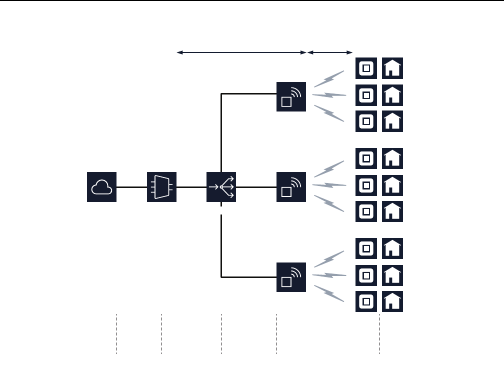
Figure 5 shows a high-level representation of the WPON solution providing a
wireless drop from a PON or P2P-based optic network to three subscriber homes.
WPON solution overview
36
WPON Product Overview
3TG-00038-AAAA-TCZZA Issue: 01
Figure 5 High-level representation of the WPON solution
The WPON solution can be used with a fiber distribution network that includes the
Nokia 7360 ISAM as shown in Figure 6; in this case, the WPON is deployed as an
extension of the ISAM.
AP
PON or P2P-
based optic
network
Fiber optic cable
HOU Subscriber
home
HOU Subscriber
home
HOU Subscriber
home
WPON solution
NNI UNI
27556
WPON Product Overview WPON solution overview
Issue: 01 3TG-00038-AAAA-TCZZA 37
Figure 6 WPON example with a 7360 ISAM
The WPON solution can also be used directly with a network that does not include
an ISAM.
A PON or a P2P-based optic network can have multiple WPONs; for example, the
EMAN that uses the 7360 ISAM shown in Figure 6 has three WPONs.
5.1.1 APs
An AP can be installed on a pole such as a utility pole or light pole, or on the outside
of a building and uses wireless line-of-sight communication with up to eight HOUs up
to 100 m away. The AP can be considered to be a directional multi-Gigabit access
point. An AP contains a GPS and magnetometer, enabling it to report its location and
orientation to the management system.
An AP can be a Head AP, Relay AP, or an Extension AP.
AP
EMAN
WirelessFiber
SubscribersWPONsPassive
outside plant
Fiber
distribution
Central
office
Network
27557
7360 ISAM
AP
AP
Splitter
WPON solution overview
38
WPON Product Overview
3TG-00038-AAAA-TCZZA Issue: 01
5.1.1.1 Head AP
The Head AP is an AP that is connected to a PON or P2P-based optic network; it
provides the optical-to-wireless conversion for the WPON. Every WPON has a Head
AP. Depending on the WPON topology, the Head AP might be the only AP in the
WPON or it might have wireless connectivity to other APs in the WPON.
A pole-mounted Head AP can connect to an Extension AP.
5.1.1.2 Relay AP
The Relay AP is an AP that has wireless connectivity to other APs in a WPON, either
to the Head AP and/or to other Relay APs in the WPON. A Relay AP cannot be
connected to a PON or P2P-based optic network.
A pole-mounted Relay AP can be connected to an Extension AP.
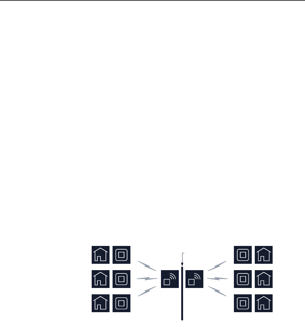
5.1.1.3 Extension AP
The Extension AP is an AP that does not have wireless connectivity to other APs in
a WPON. It can be installed with a Head AP or Relay AP on a pole to provide wider
wireless coverage, such as to HOUs on houses on both sides of a street. In this case
the pair of APs are connected to each other through a 1 Gigabit electrical Ethernet
cable that handles all the traffic between the two APs. Figure 7 shows an AP pair,
with each AP of the AP pair employing wireless line-of-sight communication with
three HOUs; the figure does not indicate which AP is the Head AP and which AP is
the Extension AP.
Figure 7 Example of an AP pair
An Extension AP cannot function as a Head AP or Relay AP.
27558
Pole
AP AP

WPON Product Overview WPON solution overview
Issue: 01 3TG-00038-AAAA-TCZZA 39
5.1.2 HOUs
An HOU provides the wireless-to-Gigabit Ethernet electrical conversion for the
WPON solution at the subscriber premises. An HOU can be considered to be a
wireless station (STA). An HOU is installed on the outside of a subscriber’s home and
uses a UTP cat-5 electrical cable for physical connectivity to CPE such as a
residential gateway inside the home. The same cable is used to provide power over
Ethernet to the HOU, using power provided by the residential gateway or from a PoE
injector. An HOU contains a GPS and magnetometer, enabling it to report its location
and orientation to the management system.
The HOU is easy to install and may be installed or replaced by subscribers if
considered appropriate.
After physical installation and power up, an HOU automatically connects to the best
AP available, reports its presence, gets configured, and initiates service per the
customer subscribed service type.
5.1.3 APs and HOUs in WPONs
At a minimum, a WPON consists of one AP and at least one HOU.
A WPON has a single NNI point at the optical connection point of the AP with the
PON or P2P-based optic network. This AP is the Head AP.
A WPON can have multiple UNI points, one at each HOU that is part of the WPON.
The number and types of APs and HOUs in a WPON depends on the topology used
for the WPON. See section 5.2 for more information about WPON topologies.
5.2 WPON topologies
The WPON solution can be set up in the following topologies:
•basic WPON topology
•wireless daisy chain topology
5.2.1 Basic WPON topology
The basic WPON topology consists of a single AP or AP pair that connects to the
PON or P2P-based optic network and provides wireless communications to HOUs
through wireless line-of-sight communication. The topology shown in Figure 5 is an
example of the basic WPON topology. The network shown in Figure 6 has three
basic WPONs.

WPON solution overview
40
WPON Product Overview
3TG-00038-AAAA-TCZZA Issue: 01
The basic WPON topology requires a Head AP to connect to the fiber optic network;
the Head AP may also connect to an Extension AP. The basic WPON topology does
not have Relay APs.
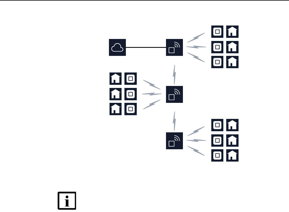
5.2.2 Wireless daisy chain topology
A WPON can be set up in a linear or a branched, non-looped, daisy chain topology
so that APs can use line-of-sight wireless communication with other APs in the
WPON. A Head AP is connected to the PON or P2P-based optic network; the other
APs in the daisy chain are Relay APs. The fiber optical connection at the Head AP
supports all the subscribers that are served by all the APs in the daisy chain. Each
Relay AP in the daisy chain automatically uses self backhaul so that all upstream
traffic is transmitted to the PON or P2P-based optic network through the Head AP. A
total of three APs, including the Head AP, with a maximum of two hops, can be
supported in a daisy chain topology. Extension APs are not included as APs and are
not included in the hop count.
In a linear daisy chain topology, an AP communicates with one downstream AP. In
a branched daisy chain topology, an AP communicates with more than one
downstream AP.
The Head AP can use wireless line-of-sight communication with up to two
downstream Relay APs and up to eight HOUs. A Relay AP can use wireless
line-of-sight communication with up to two APs (including one upstream AP, which
could be the Head AP or another Relay AP), and up to eight HOUs for a maximum
of three APs in total in the daisy chain topology. The Relay AP can also function as
a connection between two APs without connecting to any HOU.
Figure 8 shows a linear daisy chain that has two Relay APs. Each of the APs in the
example has wireless communications with three HOUs.
WPON Product Overview WPON solution overview
Issue: 01 3TG-00038-AAAA-TCZZA 41
Figure 8 Example of a linear daisy chain topology
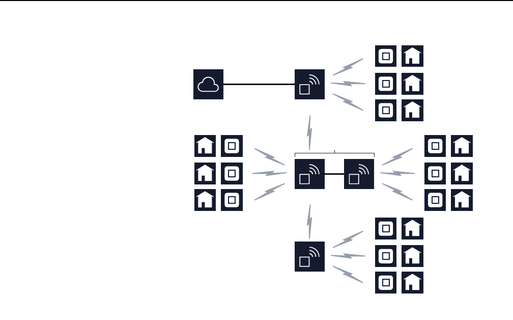
If an AP pair is used in a daisy chain, the Extension AP is not part of the daisy chain.
Figure 9 shows an example of a daisy chain that has a Relay AP that is part of an AP
pair.
Note — APs to be used in a daisy chain must be ordered from
Nokia for use as a Head AP or as Relay APs.
Head AP
PON
Fiber optic cable
27559
Relay AP
Relay AP
WPON solution overview
42
WPON Product Overview
3TG-00038-AAAA-TCZZA Issue: 01
Figure 9 Example of a daisy chain topology that has an AP pair
5.3 WPON architecture
A WPON is made up:
•an underlay network
•one or more overlay networks
5.3.1 Underlay network
The underlay network serves as an IP-based network that provides connectivity
between all the APs and HOUs in the WPON. The underlay network uses RIP for
route distribution and routing for the APs and HOUs using IP addresses that are
assigned by a DHCP server hosted in the Head AP.
The Head AP has an internal DHCP server and it delivers IP addresses to the HOUs.
Other APs perform DHCP relay. The IGMP proxy function is in the Head AP,
A WPON has a single underlay network.
The underlay network is managed through the WPON manager. See section 5.5.1
for more information about the WPON manager.
Head AP
PON
Fiber optic cable
27560
Relay AP
Relay AP Extension
AP
AP pair*
*The Extension AP is not part of the daisy chain

WPON Product Overview WPON solution overview
Issue: 01 3TG-00038-AAAA-TCZZA 43
5.3.2 Overlay network
The overlay network is a virtual network that provides L2 connectivity between an
HOU and its associated AP through the use of a GRE tunnel. The overlay network
provides logical P2P connectivity on top of the underlay network. The WPON solution
behaves like a L2 network where Ethernet frames are cross connected on a tagged
VLAN basis between the NNI (which is an AP) and UNI (which is an HOU).
A WPON has an overlay network for each HOU in the WPON.
If an HOU is associated with an AP that is part of a basic WPON topology, the AP
(which is a Head AP) and the HOU function as a Layer 2 switch with the AP being
the NNI point and a GRE tunnel endpoint and with the HOU being the UNI point and
the other GRE tunnel endpoint.
The GRE tunnel is always setup between head-AP and UNI port, regardless of
WPON topology used.
A GRE tunnel carries Ethernet frames both directions between the HOU and AP.
Each HOU has a private IP address and an X.509 certificate. The Head AP has a
DHCP server to assign internal IP addresses, with each wireless segment having its
own subnet. In the AP, the remote IP address is unspecified and learned
dynamically, and each GRE tunnel in the WPON is assigned a unique key. The
DSCP field of the IP header of the GRE tunnel packets is used to preserve QoS
inside the WPON. The DSCP values match the traffic class to which the flow carried
inside is mapped. On the wireless interfaces, queue selection is done based on the
DSCP values.
For multicast traffic, an IGMP proxy is used in the AP to dynamically build the
multicast forwarding tree so that multicast traffic is passed to the GRE tunnels for
delivery to the HOUs.
In the downstream direction, the AP transmits only subscriber-specific traffic
(including multicast traffic that the subscriber subscribes to) over the overlay network
to the associated HOU (that is, it is the AP, not the HOU, that differentiates traffic that
is not intended for the subscriber associated with each HOU, for example, traffic with
an unknown destination or traffic destined for other stations associated with the AP).
APs use priority queues on a weighted fair queuing basis to ensure that each HOU
gets a fair share of the bandwidth (upstream and downstream).
Overlay networks, including GRE tunnels, are created and managed through the
WPON manager. See section 5.5.1 for more information about the WPON manager.
5.4 WPON services
The WPON solution supports the following services:
•high speed Internet
•voice over IP
•broadcast TV
WPON solution overview
44
WPON Product Overview
3TG-00038-AAAA-TCZZA Issue: 01
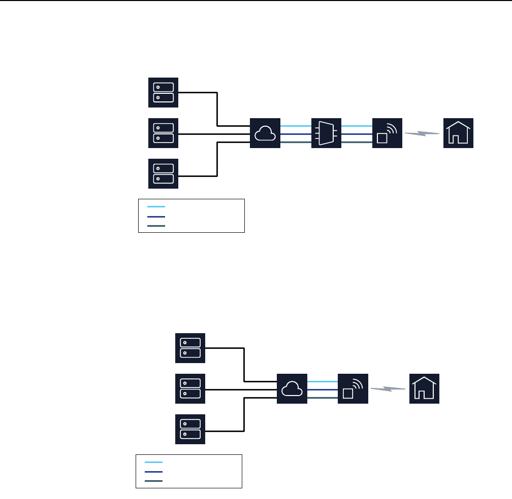
Figure 10 shows an example of a WPON supporting all three of the above services
when the WPON is deployed as an extension of an ISAM.
Figure 10 WPON service support with an ISAM
Figure 11 shows an example of a WPON supporting all three of the above services
when the WPON is deployed independently of an ISAM to provide layer 2 service.
Figure 11 WPON service independent an ISAM
The WPON transports the above three services, meaning that they are transparent
to the WPON. The WPON can support a voice service, but this requires an external
solution.
Server
Server
Server AP
ISAM
EMAN
High Speed Internet
Voice over IP
Broadcast TV
27662
Server
Server
Server AP
EMAN
High Speed Internet
Voice over IP
Broadcast TV
27663

WPON Product Overview WPON solution overview
Issue: 01 3TG-00038-AAAA-TCZZA 45
5.5 WPON management
The following are used for management of the WPON solution:
•WPON manager (section 5.5.1)
•Nokia Altiplano (section 5.5.2)
•Bluetooth (section 5.5.3)
5.5.1 WPON management through the WPON manager
The WPON manager is based on the Altiplano Management System (described in
section 5.5.2) and it provides web server management for the WPON solution. The
WPON manager serves as the element manager for the WPON and allows you to
configure the following:
•equipment deployment, specifically provisioning of the basic infrastructure such
as hardware components of APs and HOUs in a WPON, including device
management configurations, targeted software version, and the interface to the
PON or P2P optical network
•the underlay network of a WPON, specifically provisioning of the wireless and/or
Ethernet interfaces of APs and HOUs, including IP addresses and underlying
network routing aspects
•the overlay networks of a WPON, specifically provisioning of loopback interfaces,
provisioning GRE tunnels by creating GRE tunnel endpoints in the WPON, and
creating services
The WPON manager:
•provides abstractions for service provisioning across the various elements in a
WPON
•is responsible for monitoring the health of the various elements in a WPON as well
as monitoring the health of services provisioned on them
•is responsible for management of the GRE tunnels in a WPON
•is responsible for IP address assignment for the underlay network and
configuration of DHCP services in the Head AP for dynamic IP assignment for all
other elements in the WPON
•controls the entire QoS configuration

WPON solution overview
46
WPON Product Overview
3TG-00038-AAAA-TCZZA Issue: 01
The WPON manager provides a GUI that provides the following:
•device list, with information such as name, type, connection status, alignment
status, and health for each AP and HOU in the WPON
•topology history that shows information such as topology version, timestamp, and
user name and allows you to view a graphical comparison of topology versions of
the WPON
•network list that provides the AP name, interface name, interface mode, IP
address, and subnet for each WPON
The WPON manager is provided as an extension or plug-in as part of the Altiplano.
When you create and provision APs and HOUs and create GRE tunnels and services
through the WPON manager, the information is passed to the Altiplano. See section
5.5.2 for more information about the Altiplano.
5.5.2 WPON management through the Nokia Altiplano
The Nokia Altiplano is a cloud-native access platform that consists of two products:
•the Nokia Altiplano Access Controller:
•The Access Controller is the domain controller for unified management of both SDN
and traditional access networks. It offers a wide range of APIs and tools, such as field
force, service fulfillment, service assurance and task center applications that help to
visualize, automate, optimize and enhance the network. It provides automation, easy
integration with the OSS/BSS and flexible programming of end-to-end services in the
access network.
•The Access Controller automates the network and provides software management,
backup and restore, and alarm collection functions
•the Nokia Altiplano Access Virtualizer:
•The Access Virtualizer is the cloud component that creates a virtualized and
centralized view of the network in the cloud. It offers the logic and primitives for
efficiently programming and monitoring the underlying network elements, without
having to deal with challenges such as node reachability and scalability when
connecting to hundreds of thousands of nodes
•The Access Virtualizer programs nodes and provides a persistent management
agent (PMA) function for the APs and HOUs in each WPON, and acts as a persistent
management agent aggregator towards the WPON manager; the persistent
management agent provides disaggregation of the management layer and
abstraction of the WPON via standard YANG models
The Altiplano provisions APs and HOUs in response to call-home messages sent by
the APs and HOUs to it after they have been created and provisioned through the
WPON manager.

WPON Product Overview WPON solution overview
Issue: 01 3TG-00038-AAAA-TCZZA 47
5.5.3 WPON management through Bluetooth
Local craft terminal access for APs and HOUs is provided through a Bluetooth
interface (classical Bluetooth, reach greater than 20 m) on the AP or HOU.
The Bluetooth interface provides access to a Bluetooth server that is used for local
management of the AP or HOU through an app on a Bluetooth-equipped mobile
phone that can be used as a local terminal to access the AP or HOU for on-site
configuration, troubleshooting, or maintenance.
The app is a Native Mobile Application, which can assist in troubleshooting the AP
and HOU in case the connection towards the WPON manager is broken.
Connection between the mobile phone and the AP or HOU is established over
Bluetooth with a Personal Area Network (PAN) Profile using the MAC address. The
MAC address is retrieved from Quick Response (QR) code during QR scanning of
the AP or HOU.
The user logs in to the app using a default password that should be changed
immediately for security reasons via the Nokia Altiplano (PMA). After first login, the
password is securely stored (hashed) on the mobile phone, so credentials do not
need to be provided by the user in upcoming logins.
The app offers the possibility of performing different setup and troubleshooting
actions, such as setup of the AP or HOU, setting the time of day, displaying some
statistics, and performing resets, including to factory settings. The app can be used
to display the MAC address, serial number, and product type.
The app allows you to upload Certificate Authority (CA) certificates to the AP and
HOU from the mobile device. Uploading can be done by selecting the option Upload
CA certificates from the app main screen after successful login has taken place.
The app user must first manually download the certificates into the Download folder
on the mobile device before they can be uploaded to the WPON devices. Only the
following CA certificate names are valid for uploading to the WPON devices:
•pmaCA.pem
•radiusCA.pem
•logserverCA.pem
If the downloaded CA certificates do not adhere to these naming rules, the app user
must manually rename the files prior to uploading them so that the files upload
successfully.
See section 9.1.1 in this document for information about using the Bluetooth interface
to configure an AP.
See section 9.2.1 in this document for information about using the Bluetooth interface
to configure an HOU.

WPON solution overview
48
WPON Product Overview
3TG-00038-AAAA-TCZZA Issue: 01
5.6 WPON planning considerations
WPON planning considerations include the following:
•planing the network:
•network topology of the APs and HOUs
•address pool for the Head AP in the public DHCP server
•IP route from Head AP's address to the WPON manager needs be configured; the
correct gateway address also be configured in the DHCP pool in the public DHCP
server
•Public DHCP server, radius server and the WPON manger need to be deployed
correctly; the following are important:
•correct CA certificate is installed to radius server, HTTPS file server (software image
repository) and WPON manager for call home
•WPON manager information is put to DHCP server as option 125 information for the
WPON head AP address pool
•correct software image is in the HTTPS file server
•APs and HOUs must have correct time and correct CA certificates
•serial numbers need to be put into the WPON manager to be able to do the
following:
•preparation of configurations for AP and HOU for their serial number, setting work
mode, L2/L3 configuration and WiGig configuration, update DHCP server
configuration in Head AP
•for configuration of option 43 in public DHCP server for permitted access device (APs
and HOUs)
•for all devices will be updated to the latest version from the WPON manager at the
same time
•for the operator to use the WPON manager to know whether the network topology is
correctly deployed
5.7 Compatible CPE
The HOU supports connection of any VLAN tagging compatible residential gateway
or router or similar Internet-access CPE that can connect to the HOU through the
Cat5 Ethernet cable attached to the HOU.
An example of CPE that can connect to the HOU is the Nokia Beacon 1 (HA-020W-A)
residential gateway.
See chapter 7 for more information about the HOU and its physical connections.

WPON Product Overview AP unit data sheet
Issue: 01 3TG-00038-AAAA-TCZZA 49
6 AP unit data sheet
6.1 AP part numbers and identification
6.2 AP general description
6.3 AP software and installation feature support
6.4 Subscriber traffic interfaces on the AP
6.5 AP LED information
6.6 AP specifications
6.7 AP wireless specifications
6.8 Performance monitoring statistics
6.9 Functional blocks
6.10 AP standards compliance
6.1 AP part numbers and identification
Table 3 provides part numbers and descriptions for the APs.

AP unit data sheet
50
WPON Product Overview
3TG-00038-AAAA-TCZZA Issue: 01
Table 3 AP part numbers and descriptions
Table 4 provides ordering information for AP accessories.
Part number Description
3FE 75103 AA This AP is designed to be used as the Head AP on a pole; it can be used with an Extension AP.
It has one fiber optic connection, one Ethernet connection, a power connection, and two baseband units. One of the
baseband units is used for wireless connections to HOUs; the other baseband unit is available for use for wireless
connections to any downstream APs in the WPON.
The fiber optic connection uses an SFP module to connect to a PON or P2P-based optic network.
The Ethernet connection is not used if the AP is not part of an AP pair.
It is local grid powered (110 or 230 VAC).
3FE 75103 AB This AP is designed to be used as a Relay AP on a pole; can be used with an Extension AP.
It has one Ethernet connection, a power connection, and three baseband units. One of the baseband units is used
for wireless connections to HOUs, one of the baseband units is for a wireless connection to an upstream AP in the
WPON, and the other baseband unit is available for wireless connections to any downstream APs in the WPON.
This AP does not have any fiber optic connections and cannot be used as a Head AP to connect to a PON or
P2P-based optic network.
The Ethernet connection is only used if the AP is part of an AP pair.
It is local grid powered (110 or 230 VAC).
3FE 75103 AC This AP is designed to be used as an Extension AP in an AP pair on a pole.
It has one Ethernet connection, a power connection, and one baseband unit. The baseband unit used is used for
wireless connections to HOUs.
This AP does not have any fiber optic connections and cannot be used as a Head AP to connect to a PON or
P2P-based optic network.
The Ethernet connection is used to connect to the other AP in an AP pair.
It is local grid powered (110 or 230 VAC).
3FE 75103 BA This AP is designed to be used as the Head AP on a wall; it cannot be used with an Extension AP.
It has one fiber optic connection, a power connection, and two baseband units. One of the baseband units is used
for wireless connections to HOUs, and the other baseband unit is available for use for wireless connections to any
downstream APs in the WPON.
The fiber optic connection uses an SFP module to connect to a PON or P2P-based optic network.
It is local grid powered (110 or 230 VAC).
3FE 75103 BB This AP is designed to be used as a Relay AP on a wall; it cannot be used with an Extension AP.
It has a power connection and three baseband units. One of the baseband units is used for wireless connections to
HOUs, one of the baseband units is for a wireless connection to an upstream AP in the WPON, and the other
baseband unit is available for wireless connections to any downstream APs in the WPON.
This AP does not have any fiber optic connections and cannot be used as a Head AP to connect to a PON or
P2P-based optic network.
It is local grid powered (110 or 230 VAC).
Note — APs to be used in a daisy chain must be ordered from
Nokia for use as a Head AP or as Relay APs.

WPON Product Overview AP unit data sheet
Issue: 01 3TG-00038-AAAA-TCZZA 51
Table 4 AP accessories
6.2 AP general description
APs are designed to provide the optical-to-wireless conversion for the WPON
solution by providing a fiber optic interface to the PON or P2P optical network along
with providing wireless 180 degree line-of-sight communication with up to eight
HOUs. Depending on the WPON topology, an AP can also provide wireless
line-of-sight communication with other APs. See chapter 5 for more information
about the WPON solution.
Connectivity from the AP to the PON or P2P-based optic network is done through an
SFP module that can be installed in the SFP cage of the AP. The SFP module can
be an SFP ONT or a P2P optical Ethernet uplink SFP.
On the wireless side, the AP uses 802.11ad supporting unlicensed 60 GHz mm
Wave wireless line-of-sight communication with 1 Gb/s peak speeds.
The AP is managed through the WPON manager and the Nokia Altiplano
cloud-native access platform. A local craft terminal access point is provided on the
AP through a Bluetooth interface (classical Bluetooth, reach greater than 20 m) for
management through an app. See section 5.5 in this document for more information
about management of the WPON solution.
The AP provides the following functions and features:
•optical to wireless conversion
•wireless Gigabit Ethernet channels
•Outside North America:
An AP provides three wireless Gigabit Ethernet channels: two channels are used to
connect to other APs, one channel is used for the drop interface to the HOU.
•In North America:
An AP provides two channels: one channel to connect to another AP, one channel is
used for the drop interface to the HOU.
Accessory Orderable part number Notes
SFP ONT 3FE 46541 AA This is an SFP module to connect a Head AP to a PON. It is
identified as G-010S-A. This SFP module must be ordered
separately
P2P 1 Gigabit
optical
Ethernet uplink
SFP
3FE 25774 AA This is an SFP module to connect a Head AP to a P2P-based
optic network with a 1 Gigabit optical Ethernet uplink.
P2P 10 Gigabit
optical
Ethernet uplink
SFP
3FE 62600 AA This is an SFP module to connect a Head AP to a P2P-based
optic network with a 10 Gigabit optical Ethernet uplink.

AP unit data sheet
52
WPON Product Overview
3TG-00038-AAAA-TCZZA Issue: 01
•in the downstream direction, the AP filters subscriber traffic and transmits it to the
respective HOUs (that is, the AP discards traffic that is not intended for the
subscriber associated with the HOU)
•can be installed on a pole such as a utility pole or a light pole (fits multiple pole
dimensions and geometries) or on the building facade
•daisy chain with other APs using self backhaul
•up to 1 Gbps aggregate capacity per HOU, supporting 1 Gbps peak speeds to up
to eight HOUs up to 100 m away
•beam-forming antennas for fast and reliable wireless connection
•built-in different antenna configurations and applications
•wide field of view for antennas: 180 degrees horizontal and 60 degrees vertical
•PON or P2P optic fiber feed (uses an SFP module)
•single mode fiber (uses SC/APC connector)
•local grid AC powered (110 or 230 VAC)
•built-in GPS and magnetometer
•IP66 protected
•compact size
•X.509 certificate-based authentication
•encryption over the air:
•WPA2-Enterprise
•IEEE 802.1X/EAP-TLS for mutual authentication
•data-confidentiality protocol GCMP, added as per 802.11ad amendment
6.3 AP software and installation feature support
AP software is managed through the WPON manager and the Nokia Altiplano; see
section 5.5.1 for information about the WPON manager and section 5.5.2 for
information about the Nokia Altiplano.
For information about installing or replacing an AP, see chapter 8 in this guide and
see the AP Installation Guide. See section 5.5.3 in this document for information
about managing the AP through its Bluetooth interface when installing or replacing
an AP.
6.4 Subscriber traffic interfaces on the AP
Table 5 describes the supported subscriber traffic interfaces for the APs.

WPON Product Overview AP unit data sheet
Issue: 01 3TG-00038-AAAA-TCZZA 53
Table 5 AP subscriber traffic interfaces
Notes
(1) The Ethernet interface is only used for connecting two APs that make up an AP pair; AP pairs are only
supported for pole-mount APs.
(2) The wireless components are described in more detail in section 6.4.2.
(3) The upstream AP can be a Rely AP or the Head AP.
6.4.1 AP physical connections and components
Figure 12 shows the AP physical connections and section 6.4.2 describes the
wireless components.
AP
Number of interfaces
PON/P2P optic
fiber
Ethernet (1) Wireless (2)
Head AP One One Two:
•one for drop to the HOUs
•one for daisy chaining to one
downstream AP
Relay AP - One Three:
•one for drop to the HOUs
•one for daisy chaining to the upstream
AP (3)
•one for daisy chaining to one or more
downstream APs
Extension AP used in
an AP pair
- One One for drop to the HOUs
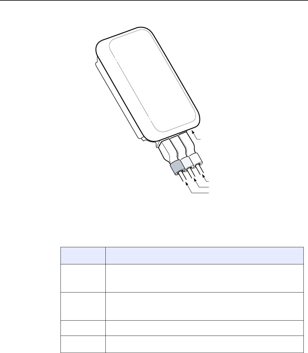
AP unit data sheet
54
WPON Product Overview
3TG-00038-AAAA-TCZZA Issue: 01
Figure 12 AP physical connections
Table 6 describes the AP physical connections and components.
Table 6 AP physical connections and components
Connection or
component
Description
PON/P2P fiber
optic connection
This connection is provided through single mode fiber optic cable with an SC/APC
connector through an SFP ONT or a P2P optical Ethernet uplink SFP.
This connection is provided on AP variants that support Head AP functionality; an IP67
cap plug is used if the connection is not supported.
Ethernet
connection
This connection is provided through an RJ 45 connector. It is used for connecting two APs
in an AP pair to each other through a 1 Gigabit electrical Ethernet cable.
This connection is provided on AP variants that can be connected as an AP pair; an IP67
cap plug is used if the connection is not used.
Power
connection
Connection to the local power grid (110 or 230 VAC) is provided through a power cable.
LED Single multifunction LED
See section 6.5 for information about the LED
(1 of 2)
Power connection
PON/P2P fiber optic connection
Ground connection
Ethernet connection
27561

WPON Product Overview AP unit data sheet
Issue: 01 3TG-00038-AAAA-TCZZA 55
6.4.2 AP wireless components
Depending on the variant, the AP has wireless components for the following:
•drop to HOUs:
•one baseband unit that has three single-tile 32-antenna/RF arrays that have a scan
range of +/- 90° azimuth, +30°+x /-30°+x elevation, antenna tiles tilted upwards,
providing total angle 180° azimuth and 60° elevation
•the 32-antenna/RF arrays use vertical polarization and are located at the center line
of the AP
•daisy chaining to an upstream or downstream AP:
•two baseband units (one for upstream and the other for downstream)
•each baseband unit has a 64-antenna/RF array that is made up of two 32-antenna
tiles and has a scan range of +/- 30° Azimuth, +/- 30° elevation, antenna tiles are not
tilted
•the 64-antenna/RF arrays use horizontal polarization and are located towards the left
and right sides of the AP
•for a wall-mounted AP, the antenna/RF arrays are angled 15° away from the wall
6.5 AP LED information
The AP has a single multi-color LED is used to signal alarms and states as described
in Table 7.
Figure 13 shows the location of the LED.
Ground
connection
This connection uses an M5 screw
Connection or
component
Description
(2 of 2)
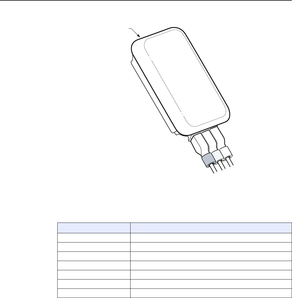
AP unit data sheet
56
WPON Product Overview
3TG-00038-AAAA-TCZZA Issue: 01
Figure 13 AP LED location
Table 7 describes the AP LED behavior.
Table 7 AP LED behavior description
6.6 AP specifications
Table 8 lists the physical specifications for the AP.
LED color and behavior LED behavior description
Red off No alarm
Red flashing Critical alarm
Red solid Major alarm
Green off OAM link is established
Green flashing slow OAM link failure
Green flashing fast Application startup
Green solid Boot function
27562
Location of LED

WPON Product Overview AP unit data sheet
Issue: 01 3TG-00038-AAAA-TCZZA 57
Table 8 AP physical specifications
Table 9 lists power consumption specifications for the AP
Table 9 AP power consumption specifications
Table 10 lists the environmental requirements for the AP.
Table 10 AP environmental requirements
6.7 AP wireless specifications
Table 11 lists the wireless specifications for the AP.
Dimensions Specifications
Height 25.2 cm
Width 16.6 cm
Depth 8.0 cm
Weight [within ± 0.5 lb (0.23 kg)] 1650 g
AP Maximum power
(not to exceed)
Condition Minimum
power
Condition
Wall-mount 27 W Maximum traffic load 17 W No traffic load
Pole-mount 27 W Maximum traffic load 17 W No traffic load
Extension 19 W Maximum traffic load 16 W No traffic load
Mounting
method
Temperature range and humidity Altitude
Pole or on an
outside wall
Operating:
-22°F to 131°F (-30°C to 55°C) ambient
temperature
5% to 85% relative humidity, non-condensing
Maximum operating altitude is
10 000 ft (3048 m) above mean sea
level
Storage:
–40°F to 140°F (–40° to 60°C)
5% to 93% relative humidity, non-condensing
Maximum non-operating altitude is
40 000 ft (12 192 m) above mean
sea level

AP unit data sheet
58
WPON Product Overview
3TG-00038-AAAA-TCZZA Issue: 01
Table 11 Wireless specifications for the AP
6.8 Performance monitoring statistics
WiGig statistics can be checked through the Bluetooth interface during installation of
the AP.
6.9 Functional blocks
Figure 14 shows the functional blocks for an AP. Note that not all functional blocks
are used in all AP variants:
•a Head AP does not have the upstream antenna/RF block
•a Relay AP does not connect to a fiber optic cable
•an Expansion AP does not:
•have upstream and downstream antenna/RF blocks
•connect to a fiber optic cable
•the 1.0 G Ethernet block is only used if the AP is part of an AP pair; a UTP cat-5
cable is used for the connection between the two APs
Specification Description
Base standard 802.11ad
Drop function 180° field of view thanks to multiple steerable beamforming high-gain patch
antenna arrays
Frequency and duplexing 60GHz / TDD
Channels #2, #3 (center frequencies 60.48, 62.64 GHz)
Channel width 2.16GHz
Modulation and coding Up to MCS8 (QPSK)
Wireless line rate (PHY) MCS8: 2.310 Gbit/s PHY
Aggregate throughput 1.5 gbps (PHY rate) drop up to 100 m
System gain (link budget) 19 dBi
Power EiRP approx 35 dBm
HPBW 14°
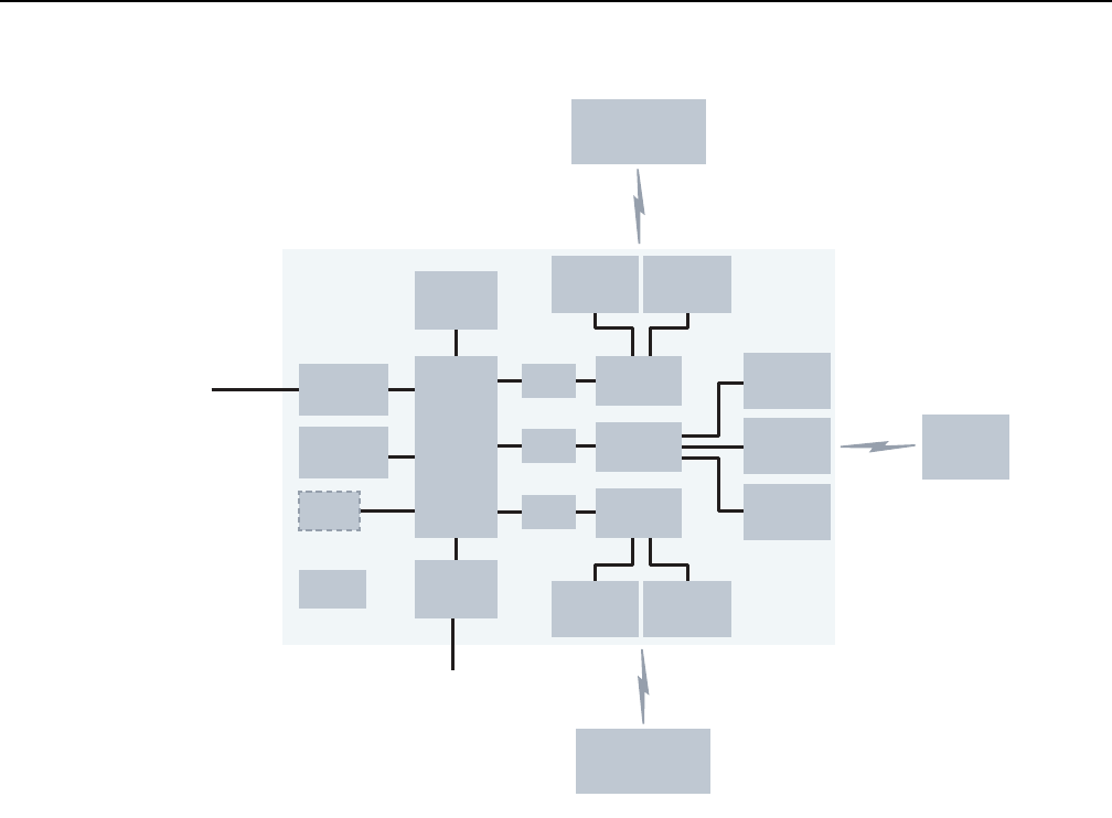
WPON Product Overview AP unit data sheet
Issue: 01 3TG-00038-AAAA-TCZZA 59
Figure 14 Functional blocks of an AP
6.10 AP standards compliance
The APs are compliant with the following standards:
•Environmental: IP 66, full sunload, ETSI class 4.1E, ANSI NEBS GR-487 core
•EN-300019-2-1 (Class T1.2)
•EN-300019-2-2 (Class T2.3)
•EN-300019-2-3 (Class T3.2))
•ETL
•FCC (Class B)/CAN ICES-003
•IEEE 802.11ad
•ITU-T G.984 (GPON interface framing)
•ITU-T G.984.2 (1.25 Gb/s, 2.5 Gb/s)
•ITU-T G.984.3 (activation with automatic discovery of a serial number and a
password)
To HOUs
To PON/P2P
optical network
if applicable
M2SFP cage
Bluetooth
GPS
Power
M2
M2
antenna/
RF
antenna/
RF
antenna/
RF
antenna/
RF
antenna/
RF
To upstream
AP if applicable
To downstream
AP if applicable
SOC
DRAM/
Flash
To the other
AP if AP pair
11 ad BB
unit
11 ad BB
unit
AP antenna/
RF
antenna/
RF
11 ad BB
unit
1 GE
27563

AP unit data sheet
60
WPON Product Overview
3TG-00038-AAAA-TCZZA Issue: 01
•ITU-T G.984.4 (standard and revised) (OMCI interface for management and
provisioning) (done by an SFP ONT installed in the fiber optic connection point of
a Head AP)
•Electromagnetic compatibility of multimedia equipment - Emission requirements
CISPR 32, EN 55032
•Electromagnetic compatibility of multimedia equipment - Immunity requirements
CISPR 35, EN55035
•Electromagnetic Compatibility (EMC) standard for radio equipment and services;
Part 1: Common technical requirements; Harmonized Standard covering the
essential requirements of article 3.1(b) of Directive 2014/53/EU and the essential
requirements of article 6 of Directive 2014/30/EU EN 301489-1
•Electromagnetic Compatibility (EMC) standard for radio equipment and services;
Part 17: Specific conditions for Broadband Data Transmission Systems;
Harmonized Standard covering the essential requirements of article 3.1(b) of
Directive 2014/53/EU EN 301489-17
•EN 60950-1, Safety of Information Technology Equipment for use in a restricted
location (per R-269)
•IEC 60950-22, EN 60950-22: Information Technology Equipment- Safety - Part 22
Equipment to be installed Outdoors
•EN 300 019 European environmental standards
•Federal Communications Commission PART 15-RADIO FREQUENCY DEVICES
Subpart C-INTENTIONAL RADIATORS Title 47 CFR Part 15. Part 15.247, Part
15.255
•UL62368-1, Outdoor ONTs to “Communication Service Equipment” (CSE) and
Indoor ONTs to Information Technology Equipment (ITE)
•Information Technology Equipment- Safety - Part 22 Equipment to be installed
Outdoors
•UL 60950-22
6.10.1 Energy-related products standby and off modes
compliance
Hereby, Nokia declares that the APs are in compliance with the essential
requirements and other relevant provisions of Directive 2009/125/EC together with
Commission Regulation (EC) No 1275/2008 and Commission Regulation (EC) No
801/2013.
The APs qualify as equipment with high network availability (HiNA) functionality.
Since the main purpose of the APs is to provide network functionality with HiNA 7
days /24 hours, the modes Off/Standby, Power Management, and Networked
Standby are inappropriate.
For information about the type and number of network ports, see “Subscriber traffic
interfaces on the AP” in this chapter.
For information about power consumption, see “AP specifications” in this chapter.

WPON Product Overview AP unit data sheet
Issue: 01 3TG-00038-AAAA-TCZZA 61
6.10.2 AP compliance statement
This device complies with Part 15 of the FCC Rules. Operation is subject to the
following two conditions:
1 This device may not cause harmful interference.
2 This device must accept any interference received, including interference that
may cause undesired operation.
Warning: Changes or modifications to this unit not expressly approved by the party
responsible for compliance could void the user's authority to operate the equipment.
NOTE: This equipment has been tested and found to comply with the limits for a
Class B digital device, pursuant to Part 15 of the FCC Rules. These limits are
designed to provide reasonable protection against harmful interference in a
residential installation. This equipment generates, uses and can radiate radio
frequency energy and, if not installed and used in accordance with the instructions,
may cause harmful interference to radio communications.
However, there is no guarantee that interference will not occur in a particular
installation. If this equipment does cause harmful interference to radio or television
reception, which can be determined by turning the equipment off and on, the user is
encouraged to try to correct the interference by one or more of the following
measures:
•Reorient or relocate the receiving antenna.
•Increase the separation between the equipment and receiver.
•Connect the equipment into an outlet on a circuit different from that to which the
receiver is needed.
•Consult the dealer or an experienced radio/TV technician for help.

AP unit data sheet
62
WPON Product Overview
3TG-00038-AAAA-TCZZA Issue: 01

WPON Product Overview HOU unit data sheet
Issue: 01 3TG-00038-AAAA-TCZZA 63
7 HOU unit data sheet
7.1 HOU part numbers and identification
7.2 HOU general description
7.3 HOU software and installation feature support
7.4 Subscriber traffic interfaces on the HOU
7.5 HOU LED information
7.6 HOU specifications
7.7 HOU wireless specifications
7.8 Performance monitoring statistics
7.9 Functional blocks
7.10 HOU standards compliance
7.1 HOU part numbers and identification
Table 12 provides part numbers and descriptions for the HOU.
Table 12 HOU part numbers and descriptions
Part number Description
3FE 47290 AA HOU with one baseband unit and one Gigabit Ethernet port.
The baseband unit is used for wireless connection to an AP.
The Gigabit Ethernet port is used for connection to CPE, such as a residential gateway, through a pre-attached 3 m
Cat5 cable. The HOU is POE-powered through the Cat5 cable.
If required, an additional Cat5 cable can be attached to the first Cat5 cable to increase its length, to a maximum
combined length of 100m.

HOU unit data sheet
64
WPON Product Overview
3TG-00038-AAAA-TCZZA Issue: 01
7.2 HOU general description
An HOU provides the wireless-to-Gigabit Ethernet electrical conversion for the
WPON solution at the subscriber premises. The HOU is installed on the facade of a
subscriber’s home and uses a Cat5 cable to physically connect to the CPE, such as
a residential gateway, inside the home. See chapter 5 for more information about the
WPON solution.
On the wireless side, the HOU is compliant with 802.11ad DMG STA supporting
unlicensed 60 GHz mm Wave wireless line-of-sight communication with 1 Gb/s peak
speeds.
The HOU is managed through the WPON manager and the Nokia Altiplano
cloud-native access platform. A local craft terminal access point is provided on the
HOU through a Bluetooth interface (classical Bluetooth, reach greater than 20 m) for
management through an app. See section 5.5 for more management information.
The HOU provides the following functions and features:
•wireless-to-Gigabit Ethernet conversion
•automatically connects to the best AP available, reports its presence, gets
configured, and initiates service per the customer subscribed service type
•beam-forming antennas for fast and reliable wireless connection
•wide field of view for antennas (180 degrees horizontal and 60 degrees vertical)
means there is no need to aim the antenna
•installed on the facade of a subscriber’s home
•provides symmetrical Ethernet connectivity at Gigabit speeds to CPE over a Cat5
cable
•PoE-powered over a pre-attached Cat5 cable that connects to the CPE or a PoE
injector (PoE 802.3at/PoE+)
•built-in GPS and magnetometer
•IP66 protected
•compact size means that it is barely noticeable on building
•X.509 certificate-based authentication
•encryption over the air:
•WPA2-Enterprise
•IEEE 802.1X/EAP-TLS for mutual authentication
•data-confidentiality protocol GCMP, added as per 802.11ad amendment
7.3 HOU software and installation feature support
HOU software is managed through the WPON manager based on the Nokia Altiplano
Management System; see section 5.5 in this document for information about the
WPON manager and Nokia Altiplano.
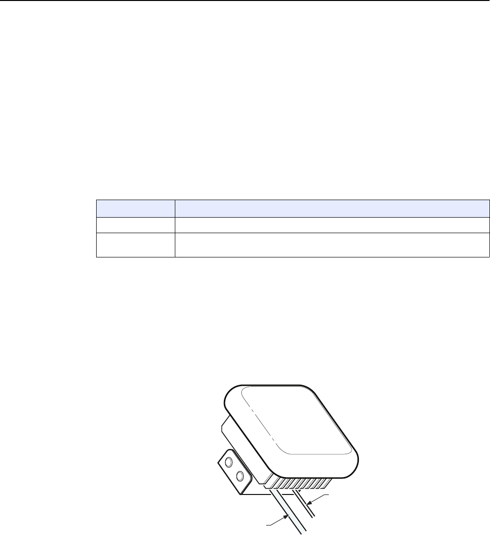
WPON Product Overview HOU unit data sheet
Issue: 01 3TG-00038-AAAA-TCZZA 65
For information about installing or replacing an HOU, see chapter 8 in this guide and
see the HOU Installation Guide. See section 5.5.3 in this document for information
about managing the HOU through its Bluetooth interface when installing or replacing
an HOU.
Note that the HOU is easy to install and may be installed or replaced by the
subscriber if considered appropriate. The HOU Installation Guide has been prepared
for use by subscribers as well as for use by operational personnel.
7.4 Subscriber traffic interfaces on the HOU
Table 13 describes the supported subscriber traffic interfaces for the HOU.
Table 13 HOU subscriber traffic interfaces
7.4.1 HOU physical connections and components
Figure 15 shows the HOU physical connections and section 7.4.2 describes the
wireless components.
Figure 15 HOU physical connections
Table 14 describes the HOU physical connections and components.
Interface Description
Wireless One 802.11ad wireless interface for communication with an AP
Ethernet One Gigabit Ethernet interface for connection to CPE; the same connection is used for
power over Ethernet
Ethernet connection
27564
Ground cable

HOU unit data sheet
66
WPON Product Overview
3TG-00038-AAAA-TCZZA Issue: 01
Table 14 HOU physical connections and components
7.4.2 HOU wireless components
The HOU has one baseband unit for wireless communication with an AP:
•the baseband unit has three single-tile 32-antenna/RF arrays that have a scan
range of +/- 90° Azimuth, +30° /-30° elevation, using a mounting kit the HOU can
be mechanically tilted upwards or downwards.
•the 32-antenna/RF arrays use vertical polarization and are located at the center
line of the HOU
7.5 HOU LED information
The HOU has a single multi-colour LED is used to signal alarms and states, as
described in Table 15.
Figure 16 shows the location of the LED.
Connection or
component
Description
Ethernet
connection
This connection is provided through an RJ 45 connector at the end of a 3 m Cat5 Ethernet
cable attached to the HOU. The cable is used for used for connecting to CPE, such as a
residential gateway.
POE (802.3at) power is provided through the same cable, using power supplied by the
residential gateway or other CPE, or supplied by a POE injector.
If required, an additional Cat5 Ethernet cable can be attached to the Cat5 Ethernet cable
to increase its length, to a maximum combined length of 100m.
Ground
connection
A ground point is provided on the back of the HOU
LED Single multifunction LED
See section 7.5 for more information about the LED
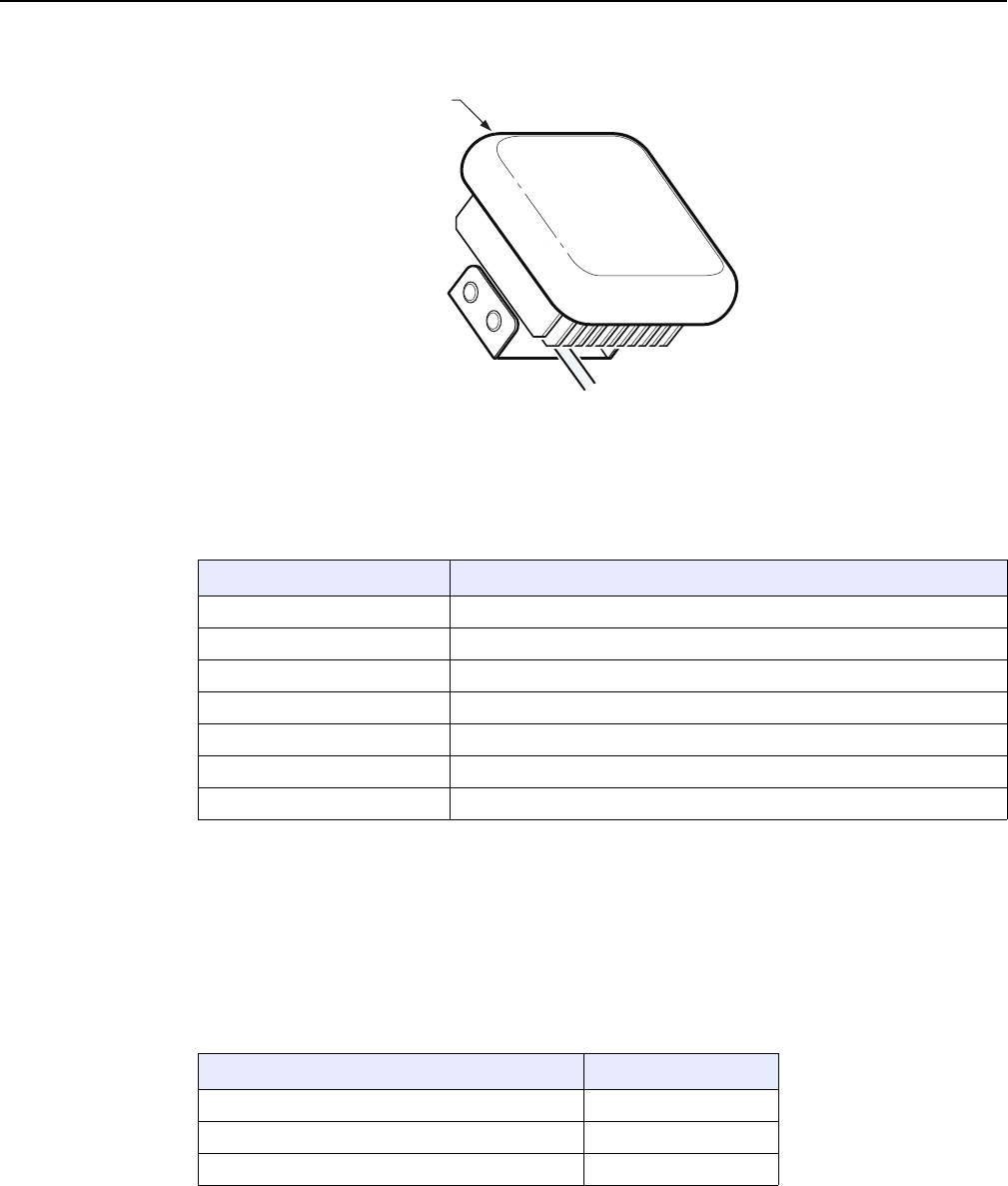
WPON Product Overview HOU unit data sheet
Issue: 01 3TG-00038-AAAA-TCZZA 67
Figure 16 HOU LED location
Table 15 describes the HOU LED behavior.
Table 15 HOU LED behavior description
7.6 HOU specifications
Table 16 lists the physical specifications for the HOU.
Table 16 HOU physical specifications
LED color and behavior LED behavior description
Red off No alarm
Red flashing Critical alarm
Red solid Major alarm
Green off OAM link is established
Green flashing slow OAM link failure
Green flashing fast Application startup
Green solid Boot function
27565
Location of LED
Dimensions Specifications
Height 13 cm
Width 13 cm
Depth 6.5 cm
(1 of 2)

HOU unit data sheet
68
WPON Product Overview
3TG-00038-AAAA-TCZZA Issue: 01
Table 17 lists power consumption specifications for the HOU.
Table 17 HOU power consumption specifications
Table 18 lists the environmental requirements for the HOU.
Table 18 HOU environmental requirements
7.7 HOU wireless specifications
Table 19 lists the wireless specifications for the HOU.
Table 19 Wireless specifications for the HOU
Weight [within ± 0.5 lb (0.23 kg)] 800 g
Maximum power
(not to exceed)
Condition Minimum
power
Condition
16 W Maximum traffic load 13 W No traffic load
Mounting
method
Temperature range and humidity Altitude
On an outside
wall
Operating:
-22°F to 131°F (-30°C to 55°C) ambient
temperature
5% to 85% relative humidity, non-condensing
Maximum operating altitude is
10 000 ft (3048 m) above mean sea
level
Storage:
–40°F to 140°F (–40° to 60°C)
5% to 93% relative humidity, non-condensing
Maximum non-operating altitude is
40 000 ft (12 192 m) above mean
sea level
Dimensions Specifications
(2 of 2)
Specification Description
Base standard 802.11ad
Drop function 180° field of view thanks to multiple steerable beamforming high-gain patch
antenna arrays
Frequency and duplexing 60GHz / TDD
Channels #2, #3 (center frequencies 60.48, 62.64 GHz)
Channel width 2.16GHz
Modulation and coding Up to MCS8 (QPSK)
(1 of 2)
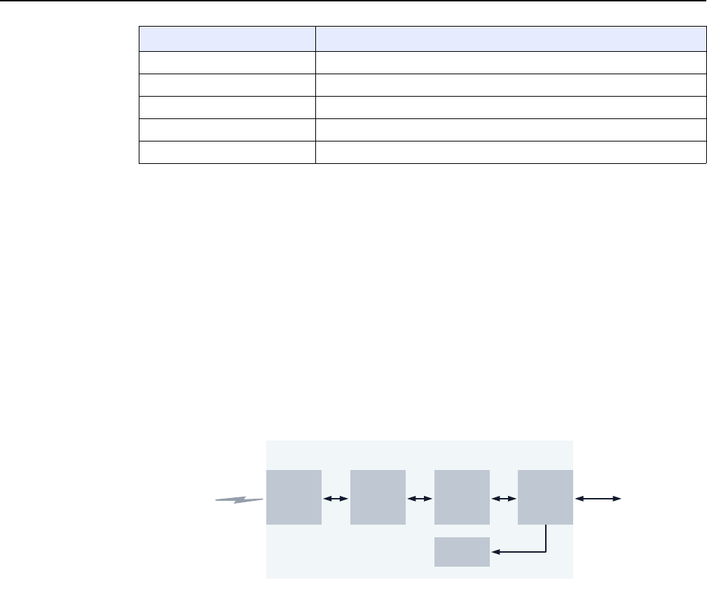
WPON Product Overview HOU unit data sheet
Issue: 01 3TG-00038-AAAA-TCZZA 69
7.8 Performance monitoring statistics
WiGig statistics can be checked through the Bluetooth interface during installation of
the HOU.
7.9 Functional blocks
Figure 17 shows the functional blocks for the HOU.
Figure 17 Functional blocks of an HOU
7.10 HOU standards compliance
The HOUis compliant with the following standards:
•IEEE 802.11ad DMG STA
•Environmental: IP 66, full sunload, ETSI class 4.1E, ANSI NEBS GR-487 core
•Electromagnetic compatibility of multimedia equipment - Emission requirements
CISPR 32, EN 55032
•Electromagnetic compatibility of multimedia equipment - Immunity requirements
CISPR 35, EN55035
Wireless line rate (PHY) MCS8: 2.310 Gbit/s PHY
Aggregate throughput 1.5 gbps (PHY rate) drop up to 100 m
System gain (link budget) 19 dBi
Power EiRP approx 35 dBm
HPBW 14°
Specification Description
(2 of 2)
Electrical
Gigabit
Ethernet
(POE)
To CPETo AP
SOC +
memory
DC
11ad
baseband
unit
32 patch
antenna
tiles
HOU
27664

HOU unit data sheet
70
WPON Product Overview
3TG-00038-AAAA-TCZZA Issue: 01
•Electromagnetic Compatibility (EMC) standard for radio equipment and services;
Part 1: Common technical requirements; Harmonized Standard covering the
essential requirements of article 3.1(b) of Directive 2014/53/EU and the essential
requirements of article 6 of Directive 2014/30/EU EN 301489-1
•Electromagnetic Compatibility (EMC) standard for radio equipment and services;
Part 17: Specific conditions for Broadband Data Transmission Systems;
Harmonized Standard covering the essential requirements of article 3.1(b) of
Directive 2014/53/EU EN 301489-17
•EN 60950-1, Safety of Information Technology Equipment for use in a restricted
location (per R-269)
•IEC 60950-22, EN 60950-22: Information Technology Equipment- Safety - Part 22
Equipment to be installed Outdoors
•EN 300 019 European environmental standards
•Federal Communications Commission PART 15-RADIO FREQUENCY DEVICES
Subpart C-INTENTIONAL RADIATORS Title 47 CFR Part 15. Part 15.247, Part
15.255
•UL62368-1, Outdoor ONTs to “Communication Service Equipment” (CSE) and
Indoor ONTs to Information Technology Equipment (ITE)
•Information Technology Equipment- Safety - Part 22 Equipment to be installed
Outdoors
•UL 60950-22
7.10.1 Energy-related products standby and off modes
compliance
Hereby, Nokia declares that the HOU is in compliance with the essential
requirements and other relevant provisions of Directive 2009/125/EC together with
Commission Regulation (EC) No 1275/2008 and Commission Regulation (EC) No
801/2013.
The HOU qualifies as equipment with high network availability (HiNA) functionality.
Since the main purpose of the HOU is to provide network functionality with HiNA 7
days /24 hours, the modes Off/Standby, Power Management, and Networked
Standby are inappropriate.
For information about the type and number of network ports, see “Subscriber traffic
interfaces on the HOU” in this chapter.
For information about power consumption, see “HOU specifications” in this chapter.

WPON Product Overview HOU unit data sheet
Issue: 01 3TG-00038-AAAA-TCZZA 71
7.10.2 HOU compliance statement
This device complies with Part 15 of the FCC Rules. Operation is subject to the
following two conditions:
1 This device may not cause harmful interference.
2 This device must accept any interference received, including interference that
may cause undesired operation.
Warning: Changes or modifications to this unit not expressly approved by the party
responsible for compliance could void the user's authority to operate the equipment.
NOTE: This equipment has been tested and found to comply with the limits for a
Class B digital device, pursuant to Part 15 of the FCC Rules. These limits are
designed to provide reasonable protection against harmful interference in a
residential installation. This equipment generates, uses and can radiate radio
frequency energy and, if not installed and used in accordance with the instructions,
may cause harmful interference to radio communications.
However, there is no guarantee that interference will not occur in a particular
installation. If this equipment does cause harmful interference to radio or television
reception, which can be determined by turning the equipment off and on, the user is
encouraged to try to correct the interference by one or more of the following
measures:
•Reorient or relocate the receiving antenna.
•Increase the separation between the equipment and receiver.
•Connect the equipment into an outlet on a circuit different from that to which the
receiver is needed.
•Consult the dealer or an experienced radio/TV technician for help.

HOU unit data sheet
72
WPON Product Overview
3TG-00038-AAAA-TCZZA Issue: 01

WPON Product Overview Installing or replacing APs and HOUs
Issue: 01 3TG-00038-AAAA-TCZZA 73
8 Installing or replacing APs and
HOUs
8.1 Installation scenarios for APs and HOUs
8.2 Replacement scenarios for APs and HOUs
8.3 AP installation and replacement
8.4 HOU installation and replacement
8.1 Installation scenarios for APs and HOUs
A number of installation scenarios are possible for APs and HOUs. Careful
consideration of the installation scenarios in advance of installation can greatly
speed up the installation process.
See the following sections for information about installing an AP or HOU:
•installing an AP: section 8.3
•installing an HOU: section 8.4
8.2 Replacement scenarios for APs and HOUs
The HOU is easy to replace and may be replaced by the subscriber if considered
appropriate.
See the following sections for information about replacing an AP or HOU:
•replacing an AP: section 8.3
•replacing an HOU: section 8.4
8.3 AP installation and replacement
An AP can be installed on a pole or on the outside of a building.
Refer to chapter 6 for detailed information about the AP before you install or replace
it.
See the AP Installation Guide for instructions on how to install or replace an AP; the
AP Installation Guide guide includes pre-installation and pre-replacement
information and steps, and includes some information about using the mobile app
through the bluetooth interface of the AP.
Installing or replacing APs and HOUs
74
WPON Product Overview
3TG-00038-AAAA-TCZZA Issue: 01
8.4 HOU installation and replacement
The HOU is designed to be installed on the outside of a subscriber’s home.
The HOU is easy to install and may be installed or replaced by the subscriber if
considered appropriate.
Table 20 indicates the HOU installation and replacement actions to be performed by
operations personnel and subscribers.
Table 20 HOU installation and replacement actions
Notes
(1) If the subscriber will be installing or replacing the HOU, some of the pre-installation or pre-replacement tasks
will involve the subscriber.
(2) The HOU Installation Guide has been prepared for use by subscribers or operations personnel.
8.4.1 HOU pre-installation tasks
The following tasks must be performed by operations personnel before an HOU can
be installed by operations personnel or by a subscriber. If the subscriber will be
installing the HOU, some of the pre-installation tasks will involve the subscriber.
Note 1 — If the HOU is to be installed by the subscriber, it is
recommended that the AP be installed before the subscriber
installs the HOU as this will help to ensure that the subscriber
installs the HOU in a suitable location.
Note 2 — If the HOU is to be installed by operations personnel,
the AP and HOU installation sequence can be determined by
the operations personnel.
Note 3 — Instructions for installing the HOU by subscribers or
by operations personnel are provided in the HOU Installation
Guide. The HOU Installation Guide has been prepared under
the assumption that the AP to which the HOU will be connected
has already been installed.
Action Operations
personnel
Subscriber
Refer to chapter 7 in this document for detailed information about the HOU ✓
Perform HOU pre-installation or pre-replacement tasks:
•see section 8.4.1 for HOU pre-installation tasks
•see section 8.4.2 for HOU pre-replacement tasks
✓✓ (1)
Install or replace an HOU according to information and steps in the HOU
Installation Guide (2)
✓✓

WPON Product Overview Installing or replacing APs and HOUs
Issue: 01 3TG-00038-AAAA-TCZZA 75
Table 21 lists the pre-installation tasks for the HOU and indicates which tasks involve
operations personnel and which tasks involve subscribers.
Table 21 Pre-installation tasks for the HOU
Once all the tasks in Table 21 have been completed, operations personnel or the
subscriber can install the HOU according to information and steps in the HOU
Installation Guide.
8.4.2 HOU pre-replacement tasks
The following tasks must be performed by operations personnel before an HOU can
be replaced by operations personnel or a subscriber. Note that if the subscriber will
be replacing the HOU, some of the pre-replacement tasks in will involve the
subscriber.
Table 22 lists the pre-replacement tasks for the HOU and indicates which tasks
involve operations personnel and which tasks involve subscribers.
Table 22 Pre-replacement tasks for the HOU
Task Operations
personnel
Subscriber
Create and provision the HOU in Altiplano with or without filling in the serial
number. If it is already known which serial number goes where, it can be added
now, or if the serial number is not yet known, it can be added after the HOU is
installed. This can be done via the GUI or can be scripted.
✓
Make sure that the following are available to the person doing the installation
(either operations personnel or subscriber):
•the HOU and any accessories that are to be supplied with the HOU
•information about the mobile app to be installed on the Bluetooth-equipped
mobile phone that will be used to configure or troubleshoot the HOU during
installation
•the HOU Installation Guide
•additional info for the install process, such as the AP location, HOU details,
and any other specific ad relevant information
✓✓
If the installation is to be done by the subscriber, make sure to provide contact
information or instructions so that the subscriber can let you know when the
installation is complete and you can do any other tasks that are required on the
network side so that the HOU can be managed from the WPON manager and
so on.
Also provide contact information to the subscriber in case the HOU needs to be
returned or replaced or there are issues during the installation.
✓✓
Task Operations
personnel
Subscriber
Unprovision the existing HOU and create and provision the replacement HOU ✓
(1 of 2)

Installing or replacing APs and HOUs
76
WPON Product Overview
3TG-00038-AAAA-TCZZA Issue: 01
Make sure that the following are available to the person doing the replacement
(either operations personnel or subscriber):
•the replacement HOU
•the HOU Installation Guide
•information about the mobile app installed on the Bluetooth-equipped
mobile phone that will be used to configure or troubleshoot the replacement
HOU
•additional info for the replacement process, including return or disposal
information for the old HOU
✓✓
If the replacement is to be done by the subscriber, make sure to provide contact
information or instructions so that the subscriber can let you know when the
replacement is complete and you can do any other tasks that are required on
the network side so that the replacement HOU can be managed from the
WPON manager and so on.
Also provide contact information to the subscriber in case there are issues
during the replacement.
✓✓
Task Operations
personnel
Subscriber
(2 of 2)

WPON Product Overview Configure an AP or HOU
Issue: 01 3TG-00038-AAAA-TCZZA 77
9 Configure an AP or HOU
9.1 AP configuration
9.2 HOU configuration
9.1 AP configuration
You can configure an AP:
•remotely through the WPON manager (see section 5.5.1)
•remotely through the Nokia Altiplano (see section 5.5.2)
•locally through Bluetooth (see section 9.1.1)
9.1.1 Local configuration of an AP
Local craft terminal access for an AP is provided through a Bluetooth interface
(classical Bluetooth, reach greater than 20 m) on the AP.
The Bluetooth interface provides access to a Bluetooth server that can be used for
local management of the AP through an app on a Bluetooth-equipped mobile phone.
You can perform configuration actions such as the following through the Bluetooth
interface of an AP:
•perform system restart
•perform reset to factory settings and restart
•synchronize the date/time of the AP with the clock of the mobile phone
•upload certificates from the mobile device to the AP
See section 5.5.3 for more information about management of the AP through the
Bluetooth interface; the AP Installation Guide has information about using the app
through the Bluetooth interface when installing or replacing an AP.
9.2 HOU configuration
You can configure the HOU:
•remotely through the WPON manager (see section 5.5.1)
•remotely through the Nokia Altiplano (see section 5.5.2)
•locally through Bluetooth (see section 9.2.1)

Configure an AP or HOU
78
WPON Product Overview
3TG-00038-AAAA-TCZZA Issue: 01
9.2.1 Local configuration of an HOU
Local craft terminal access for an HOU is provided through a Bluetooth interface
(classical Bluetooth, reach greater than 20 m) on the HOU.
The Bluetooth interface provides access to a Bluetooth server that can be used for
local management of the HOU through an app on a Bluetooth-equipped mobile
phone.
You can perform configuration actions such as the following through the Bluetooth
interface of an HOU:
•perform system restart
•perform reset to factory settings and restart
•synchronize the clock of the HOU with the clock of the mobile phone
•upload certificates from the mobile device to the HOU
See section 5.5.3 for more information about management of the HOU through the
Bluetooth interface; the HOU Installation Guide has information about using the
Bluetooth interface when installing or replacing an HOU.

WPON Product Overview Fiber optic maintenance
Issue: 01 3TG-00038-AAAA-TCZZA 79
10 Fiber optic maintenance
10.1 Purpose
This chapter provides the steps for proper maintenance of fiber optic devices including fiber optic
receptacles and connectors.
10.2 General
Proper maintenance of fiber optic devices consists of inspection and, if necessary, cleaning of fiber
optic receptacles and connectors. Recommendations for handling fiber optic devices including
fiber optic jumper cables as well as the recommended acceptance criteria for fiber optic device
inspections appear below.
10.2.1 Handling considerations
Consider the following when handling fiber optic devices and accessories.
•The bend radius for single-mode optical cable should not be less than 2 in. (102 mm), and the
bend radius for multimode optical cable is 6 in. (152 mm).
•Handle cables with care; avoid twisting the cable while turning its connectors or routing the
cable during installation.
•Connect or disconnect a connector by holding the sides of the connector and pulling gently.
•Do not touch the fiber cable end-faces.
•Do not expose the cable to excessive heat.
•Do not allow connectors to strike or drag across work surfaces, including the floor.
•Do not allow cables to support any weight.
•Do not use cable ties to secure fiber optic cables.
•Do not crush or damage fibers by placing objects on top of a cable or a connector, or by rough
handling while mounting other nearby devices.
•Keep dust and contaminants away from fiber optic surfaces.
•Keep dust caps on connectors and input/output plugs on receptacles until just prior to
installation.
•Store unused dust caps and plugs in an anti-static, zipper-locked plastic bag for future use.
•Replace dust caps and plugs if they:
•fall on the floor
•are cracked or damaged in any way
•are dirty or exposed to dust in the environment
Figure 18 shows the main parts of a fiber optic cable.
Note — Do not pull on the boot off the connector.
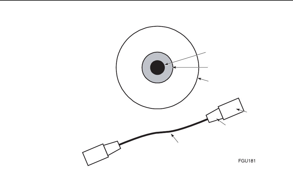
Fiber optic maintenance
80
WPON Product Overview
3TG-00038-AAAA-TCZZA Issue: 01
Figure 18 Parts of a fiber optic cable
10.2.2 Fiber optic jumper cable care
Use the following guidelines to care for fiber optic jumper cables.
•Store all unused fiber optic jumper cables in a cabinet.
•Hang all unused fiber jumper optic cables on a cable rack, or lay them flat in a cupboard.
•Ensure there is no tension on the fiber optic cable, or any sharp bending, twisting, or kinks
(micro-bends).
•The radius of the bend should meet the specifications of the manufacturer, or be at least 1.5
in. (38 mm).
•When the fiber-optic jumper cable is not in use, cover the end connectors with the dust caps.
10.2.3 Acceptance criteria for fiber optic device
inspections
Fiber optic connectors and receptacles must be visually inspected before every connection,
including the first-time installation of components still in their original packaging. After the fiber
optic devices pass inspection and the connection is made, it is not necessary to disassemble the
connection for inspection.
Core
Cladding
Ferrule
Boot
Cable
Connector

WPON Product Overview Fiber optic maintenance
Issue: 01 3TG-00038-AAAA-TCZZA 81
The following guidelines apply to acceptance criteria.
•Loose contamination of any kind is not acceptable and must be cleaned from the end-face.
•For inspection purposes, pits are to be treated the same as non-removable contamination.
•When measuring oddly shaped contamination (non-round shapes), use the largest dimension.
•If contamination falls across more than one zone, use the acceptance criteria of the most
stringent zone.
•For multifiber cable, each end-face must meet the inspection criteria.
10.2.4 Acceptance criteria
Acceptance criteria for single-mode end-faces are provided in Table 23. The zones referred to in
Table 23 are illustrated in Figure 19.
The result of an inspection can be one of three conditions:
•preferred
•acceptable
•unacceptable
Table 23 Single-mode end-face inspection acceptance criteria
Zone Diameter Acceptance criteria (number and size)
Non-removable
(contamination of pits)
Scratches
Core 9 µm None None
Core zone <50 µm None None
Cladding zone 50 to 120 µm Quantity: 3 max.
Diameter: 5 µm max.
Quantity: 2 max.
Width: 2 µm max.
Epoxy zone 120 to 130 µm Quantity: no limit
Diameter: 10 µm
No limit
Contact zone 130 to 250 µm Quantity: no limit
Diameter: 10 µm
No limit
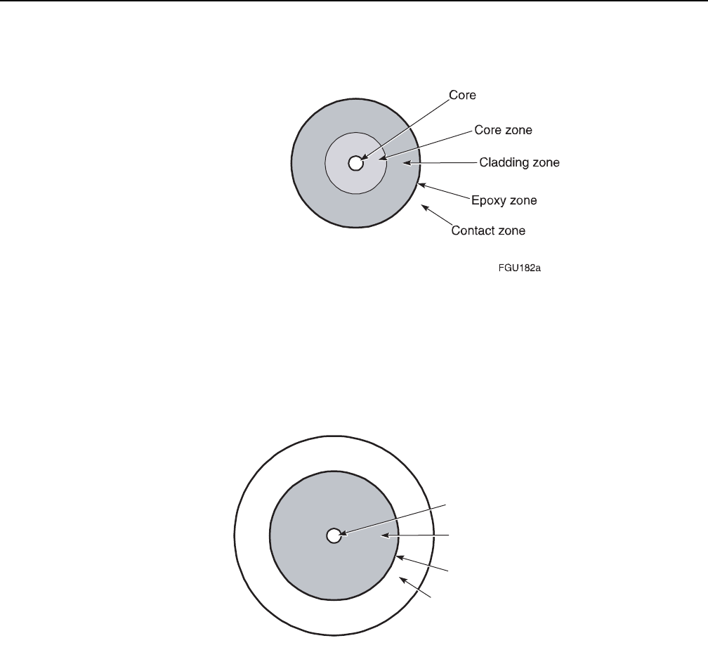
Fiber optic maintenance
82
WPON Product Overview
3TG-00038-AAAA-TCZZA Issue: 01
Figure 19 Single-mode end-face zones
The preferred condition of an end-face is shown in Figure 20. There should be no evidence of
contamination, scratches, or any defect. Figure 20 also identifies the end-face zones shown in
Figure 19. For clarity, the zones are not shown to scale, and the core and core zones are shown
as one zone.
Figure 20 Preferred condition of fiber optic end-face
Table 24 illustrates acceptable and unacceptable inspections.
Core and core zone
Cladding zone
Epoxy zone
Contact zone
FGU184
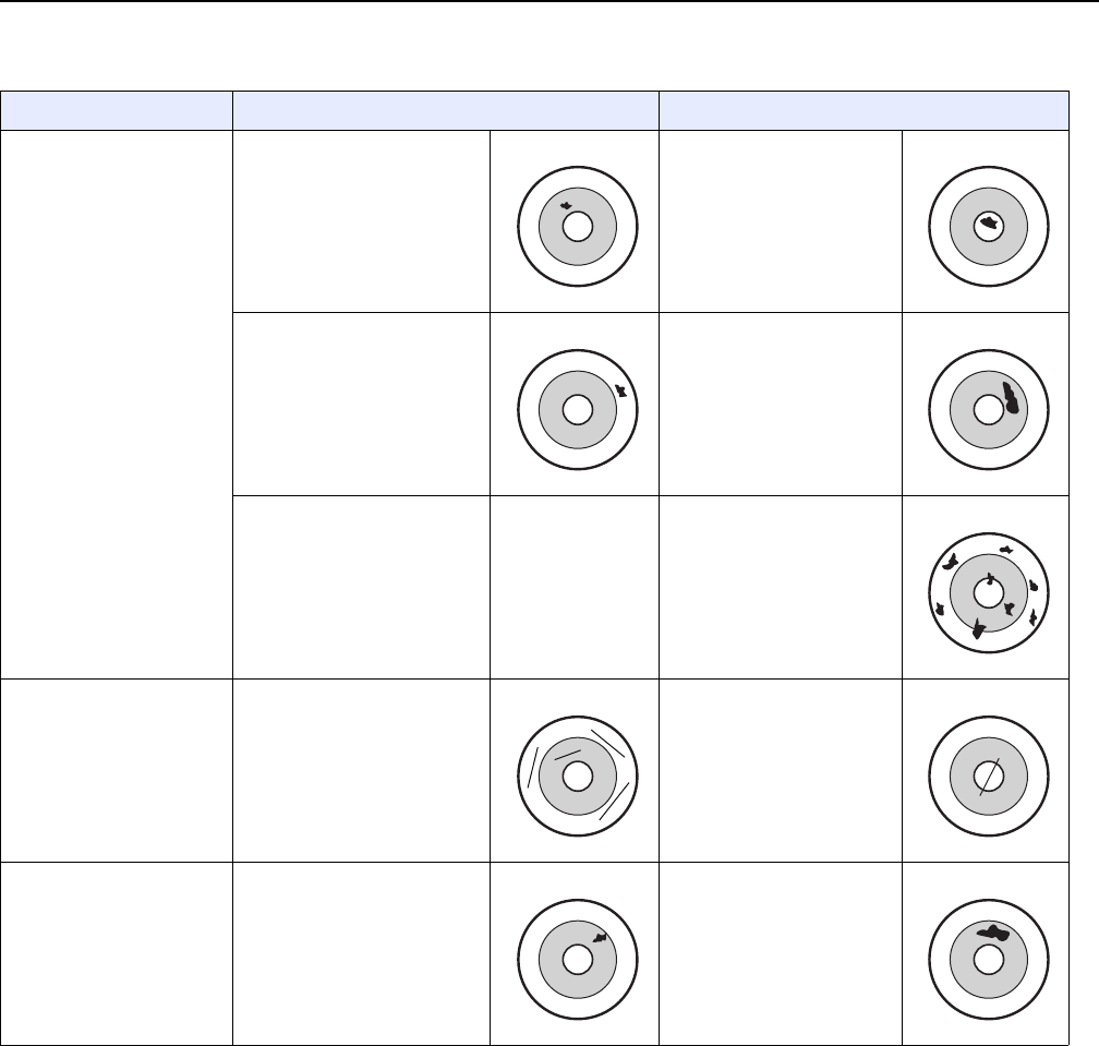
WPON Product Overview Fiber optic maintenance
Issue: 01 3TG-00038-AAAA-TCZZA 83
Table 24 Acceptable and unacceptable conditions for fiber optic end-faces
10.3 Prerequisites
For fiber optic connection inspection, you need an inspection kit or equivalent equipment that may
contain the following items:
•200x video microscope
•video monitor
Criteria Acceptable Unacceptable
Contamination, particles,
or pits in single-mode fiber
Contamination within cladding
zone, but outside core zone
Diameter is < 5 µm
Contamination in core zone
Contamination in contact zone
Diameter is < 10 µm
Contamination (large
particle) in cladding zone
Diameter is > 10 µm
— — Removable contamination
(oil)
Scratches in single-mode
fiber
One scratch in cladding zone,
or multiple scratches in a
contact zone
One scratch through core
Contamination particles or
pits in multi-mode fiber
Contamination in cladding or
epoxy zone
Diameter is < 10 µm
Contamination, large
particle in cladding zone
Diameter is > 10 µm

Fiber optic maintenance
84
WPON Product Overview
3TG-00038-AAAA-TCZZA Issue: 01
•adapters for connectors and receptacles
•instructions for the use of the kit components
The following list contains the methods used to clean a fiber optical connector. The items are listed
numerically, in order of the most preferred method.
1 a cleaner cassette
2 a lint-free cloth
3 a stick cleaner (swab)
For fiber optic cleaning, you need the following items depending on which cleaning method you
use:
•Cassette cleaner (reel type or equivalent), or lint-free, nonabrasive cloths
•Optical grade stick cleaners (swabs) that have a tightly wrapped tip (1.25 mm, 2.50 mm and
4.0 mm)
•Pure optical-grade isopropyl alcohol for cleaning connector end-faces
•A can of contaminant-free compressed air (dry nitrogen) for removing dust from connectors
(ferrule and end-face surfaces)
You may also require:
•dust caps for connectors
•anti-static, zipper-locked plastic bags
10.4 Parts list
None.
10.5 Recommended tools
None.
Note — Do not use commercially compressed air or house air.
Note — Do not use pink anti-static bags.
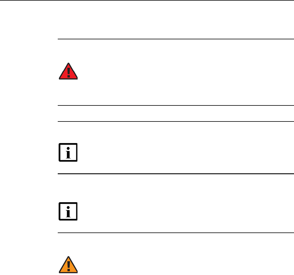
WPON Product Overview Fiber optic maintenance
Issue: 01 3TG-00038-AAAA-TCZZA 85
10.6 Procedure
Use this procedure to inspect and, if necessary, clean the fiber optic cable connectors.
1Disconnect any power to the fiber optic device before inspection.
2Gently disconnect the fiber optic connector from the receptacle.
3Inspect the cable jacket for nicks, cuts, bends, kinks, or other signs of damage.
4Inspect the ferrule for signs of damage, for example scratches, cracks, or damaged guide
holes (badly worn or out-of-round).
5Using the inspection kit, inspect the receptacle.
Determine whether the receptacle is contaminated (does not pass acceptance criteria
documented in “Acceptance criteria”).
aIf yes, go to step 8.
bIf no, go to step 7.
Danger — Never look into the end of an optical cable while optical
power is being applied to the fiber. When cleaning or taking
measurements, avoid eye exposure to open-ended fibers and optical
connectors. The fibers and connectors may be connected to a laser
transmitter. Use a microscope and video monitor when inspecting the
end-face.
Note — Do not use the cable if there is damage.
Note — Do not use the device if there is damage.
Warning 1 — Clean fiber optic receptacles only when the receptacles
are connected for the first time, or if there is evidence of contamination.
Warning 2 — Always use the proper cleaning materials, otherwise the
fiber optic equipment may become contaminated.
Fiber optic maintenance
86
WPON Product Overview
3TG-00038-AAAA-TCZZA Issue: 01
6Using the inspection kit, inspect the connector.
Determine whether the connector is contaminated (does not pass acceptance criteria
documented in “Acceptance criteria”).
aIf yes, go to step 8.
bIf no, go to step 7.
7Reconnect the connector and receptacle.
iCheck that fiber optic connection is functioning properly.
ii Go to step 17.
8Clean the connector or receptacle by gently wiping the ferrule and end-face surfaces using
a cleaner cassette or a dry lint-free cloth.
9Inspect the connector or receptacle.
Determine whether the connector or receptacle is contaminated (does not pass acceptance
criteria documented in “Acceptance criteria”)
aIf yes, go to step 10.
bIf no, go to step 7.
Warning 1 — While cleaning a fiber optic connector, do not touch the
surface of the connector with your fingers.
Warning 2 — Always use the proper cleaning materials, otherwise the
fiber optic equipment may become contaminated.
Warning — Be careful to maintain a bend radius of no less than 1.5
inches (3.8 cm) when connecting the fiber optic cable. Too small of a
bend radius in the cable can result in damage to the optic fiber.
Note 1 — Do not use optical devices that do not function properly.
Note 2 — In a fiber distribution network, it is an industry best practice to
use APC-based connections or spliced connections to avoid any potential
network problems. Nokia recommends that the unused ports of splitters
be terminated into an APC-based connector.

WPON Product Overview Fiber optic maintenance
Issue: 01 3TG-00038-AAAA-TCZZA 87
10 If the connector or receptacle fails the inspection, clean the connector or receptacle by gently
wiping the ferrule and end-face surfaces using a cleaner cassette that has a drop of
optical-grade isopropyl alcohol applied to it. Alternately, use a lint-free cloth that has a drop
of optical-grade isopropyl alcohol applied to it.
11 Remove any alcohol residue by gently wiping the ferrule and end-face surfaces with a dry
section of cleaner cassette, or a lint-free cloth.
12 Inspect the connector or receptacle.
Determine whether the connector or receptacle is contaminated (does not pass acceptance
criteria documented in “Acceptance criteria”)
aIf yes, go to step 13.
bIf no, go to step 7.
13 If necessary, repeat step 8 through step 12 until the connector or receptacle passes the
inspection.
14 If the connector or receptacle continues to fail inspection after several attempts at cleaning,
use the canned, compressed air to remove any dust or debris.
15 Inspect the connector or receptacle.
Determine whether the connector or receptacle is contaminated (does not pass acceptance
criteria documented in “Acceptance criteria”)
aIf yes, go to step 16.
bIf no, go to step 7.
Note — You may need to open the cleaner cassette window by hand to
apply the alcohol to the cassette.
Note — Do not allow the extension tube of the can to touch the fiber.

Fiber optic maintenance
88
WPON Product Overview
3TG-00038-AAAA-TCZZA Issue: 01
16 If the connector or receptacle fails the inspection, repeat step 14 through step 15 again until
inspection is passed or fiber optic device is considered damaged and unusable.
17 STOP. This procedure is complete.
Note — Typically you should not use a fiber optic device that does not
pass inspection. However, only a live test informs you if a connector or
receptacle cannot be used.

WPON Product Overview Glossary
Issue: 01 3TG-00038-AAAA-TCZZA 89
11 Glossary
This glossary provides the expansions and optional descriptions of most acronyms
and initialisms that appear in the WPON documentation.
ALED Alcatel-Lucent Electronic Delivery
ANSI American National Standards Institute
AP Access Point
CRoHS China Restriction of Hazardous Substances
DHCP Dynamic Host Configuration Protocol
DSCP Differentiated Services Code Point
EFUP Environment-Friendly User Period
EIP Electronic Information Products
EMAN Ethernet Metropolitan Area Network
EMC ElectroMagnetic Compatibility
EMI Electromagnetic Interference
ESD ElectroStatic Discharge
ETSI European Telecommunications Standards Institute
FCC Federal Communications Commission
GEM Generic Equipment Mode
GPS Global Positioning System
GRE Generic Routing Encapsulation
GUI Graphical User Interface
HOU Home Outside Unit
HST Hazardous Substances Table
IP Internet Protocol
L2 Layer 2
LED Light Emitting Diode
MAC Media Access Control
MCV Maximum Concentration Value

Glossary
90
WPON Product Overview
3TG-00038-AAAA-TCZZA Issue: 01
NNI Network Node Interface
OLCS Online Customer Support
ONT Optical Network Terminal
P2P Point to Point
PAN Personal Area Network
PDF Portable Document Format
PMA Persistent Management Agent
PoE Power over Ethernet
PON Passive Optical Network
QR Quick Response
RIP Routing Information Protocol
SC Snap Connect
SFP Small Form-factor Pluggable
TV Television
UL Underwriters’ Laboratories
UNI User Network Interface
QoS Quality of Service
VAC Volts Alternating Current
VLAN Virtual Local Area Network
WPON Wireless PON
YANG Yet Another Next Generation

Copyright 2018 Nokia.
<< doc part number is tbd >>
FCC Statement
Any Changes or modifications not expressly approved by the party responsible for compliance could void
the user’s authority to operate the equipment.
This device complies with part 15 of the FCC Rules. Operation is subject to the following two conditions:
(1) This device may not cause harmful interference, and
(2) This device must accept any interference received, including interference that may cause undesired
operation.
FCC Radiation Exposure Statement:
This equipment complies with FCC radiation exposure limits set forth for an uncontrolled
environment .This equipment should be installed and operated with minimum distance
25cm between the radiator& your body.
Note: This equipment has been tested and found to comply with the limits for a Class B digital
device, pursuant to part 15 of the FCC Rules. These limits are designed to provide reasonable
protection against harmful interference in a residential installation. This equipment generates, uses
and can radiate radio frequency energy and, if not installed and used in accordance with the
instructions, may cause harmful interference to radio communications. However, there is no
guarantee that interference will not occur in a particular installation. If this equipment does cause
harmful interference to radio or television reception, which can be determined by turning the
equipment off and on, the user is encouraged to try to correct the interference by one or more of
the following measures:
—Reorient or relocate the receiving antenna.
—Increase the separation between the equipment and receiver.
—Connect the equipment into an outlet on a circuit different from that to which the receiver is
connected.
—Consult the dealer or an experienced radio/TV technician for help.
it is not permitted to use the product on aircraft or satellites.