Nokia Bell 7577WPONAPP WPON User Manual WPON AP Product Guide
Nokia Shanghai Bell Co. Ltd. WPON WPON AP Product Guide
UserManual.wiki
>
Nokia Bell
>
7577WPONAPP User Manual
User Manual
Navigation menu
Upload a User Manual
Namespaces
Wiki Guide
HTML
PDF
Info
Views
User Manual
Discussion / Help
Navigation


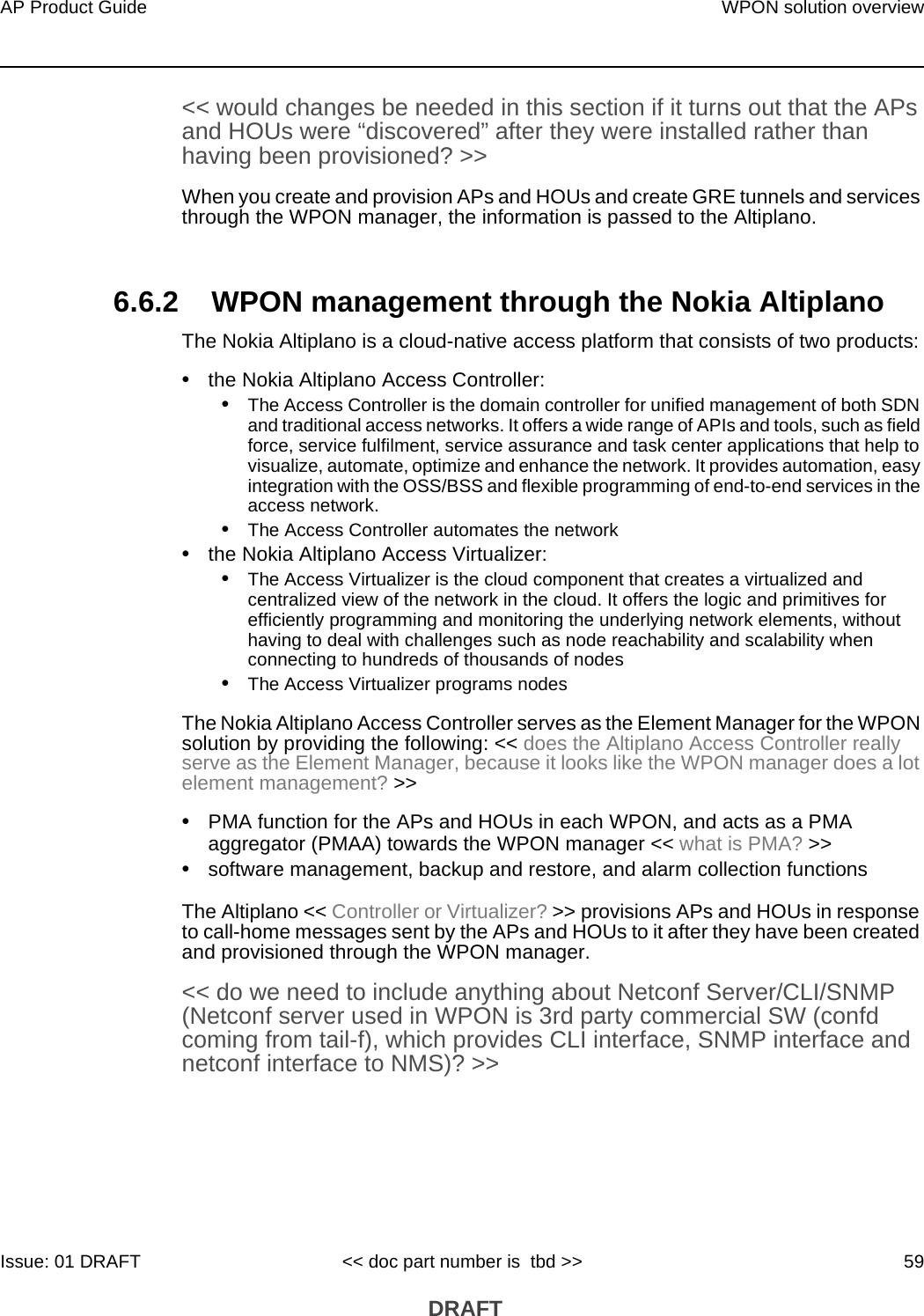
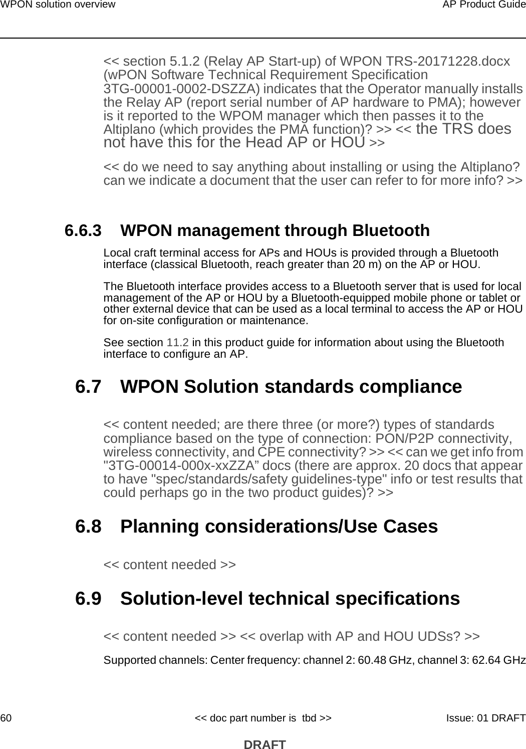

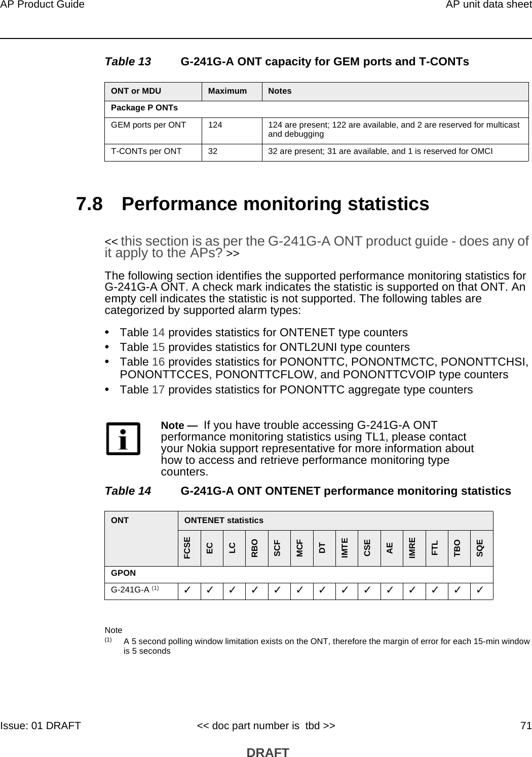
![AP unit data sheet70AP Product Guide<< doc part number is tbd >> Issue: 01 DRAFT DRAFTTable 10 AP physical specificationsTable 11 lists power consumption specifications for the AP. Table 11 AP power consumption specificationsTable 12 lists the environmental requirements for the AP.<< need to verify >>Table 12 AP environmental requirements7.7 GEM ports and T-CONTs<< this section is as per the G-241G-A ONT product guide - does any of it apply to the APs? >>Table 13 lists the maximum number of supported T-CONTs and GEM ports for G-241G-A ONT. Not all ONTs will be supported in all of the releases indicated the table. See the appropriate release Customer Release Notes for the most accurate list of supported devices.Dimensions SpecificationsHeight << need >>Width << need >>Depth << need >>Weight [within 0.5 lb (0.23 kg)] << need >>AP Maximum power (not to exceed) Condition Minimum power Condition<< need >> << need >> << need >> << need >> << need >><< need >> << need >> << need >> << need >> << need >><< need >> << need >> << need >> << need >> << need >>Mounting method Temperature range and humidity AltitudeUtility pole or on an outside wall Operating:23F to 122F (-5C to 50C) ambient temperature5% to 85% relative humidity, non-condensingMaximum operating altitude is 10 000 ft (3048 m) above mean sea levelStorage:–40F to 140F (–40 to 60C) 5% to 93% relative humidity, non-condensingMaximum non-operating altitude is 40 000 ft (12 192 m) above mean sea level](https://usermanual.wiki/Nokia-Bell/7577WPONAPP/User-Guide-3925286-Page-70.png)