Nokia Bell 7577WPONAPP WPON User Manual WPON AP Product Guide
Nokia Shanghai Bell Co. Ltd. WPON WPON AP Product Guide
User Manual

Nokia — Proprietary and confidential
Use pursuant to applicable agreements
WPON
WPON AP-Pole Product Guide
<< doc part number is tbd >>
Issue: 01 DRAFT
March 29, 2018
AP Product Guide

2
AP Product Guide
<< doc part number is tbd >> Issue: 01 DRAFT
Nokia is a registered trademark of Nokia Corporation. Other products and company
names mentioned herein may be trademarks or tradenames of their respective
owners.
The information presented is subject to change without notice. No responsibility is
assumed for inaccuracies contained herein.
© 2018 Nokia.
Contains proprietary/trade secret information which is the property of Nokia and must
not be made available to, or copied or used by anyone outside Nokia without its
written authorization. Not to be used or disclosed except in accordance with
applicable agreements.

AP Product Guide Preface
Issue: 01 DRAFT << doc part number is tbd >> 3
1 Preface
This preface provides general information about the documentation for the Access
Point (AP) of the Nokia WPON solution.
1.1 Scope
The documentation for the AP provides information about safety, features and
functionality, ordering, hardware installation and maintenance, and software
installation procedures for the AP in the current release of the WPON solution.
1.2 Audience
The documentation for the AP is intended for planners, administrators, operators,
and maintenance personnel involved in installing, upgrading, or maintaining the AP.
1.3 Required knowledge
The reader must be familiar with general telecommunications principles.
1.4 Acronyms and initialisms
The expansions and optional descriptions of most acronyms and initialisms appear
in the glossary.
1.5 Assistance and ordering phone numbers
Nokia provides global technical support through regional call centers. Phone
numbers for the regional call centers are available at the following URL:
http://support.alcatel-lucent.com.
For ordering information, contact your Nokia sales representative.

Preface
4
AP Product Guide
<< doc part number is tbd >> Issue: 01 DRAFT
1.6 Nokia quality processes
Nokia’s AP quality practices are in compliance with TL 9000 requirements.These
requirements are documented in the Fixed Networks Quality Manual
3FQ-30146-6000-QRZZA. The quality practices adequately ensure that technical
requirements and customer end-point requirements are met. The customer or its
representatives may be allowed to perform on-site quality surveillance audits, as
agreed upon during contract negotiations
1.7 Safety information
For safety information, see the appropriate safety guidelines chapter.
1.8 Documents
Documents are available from Nokia using ALED or OLCS.
Procedure 1 To download a ZIP file package of the customer documentation
1Navigate to http://support.alcatel-lucent.com and enter your user name and password. If you
are a new user and require access to this service, please contact your Nokia sales
representative.
2From the Technical Content for drop-down menu, choose the product.
3Click on Downloads: Electronic Delivery.
4Choose Documentation from the drop-down menu and click Next.
5Select the image from the drop-down menu and click Next.
6Follow the on-screen directions to download the file.
AP Product Guide Preface
Issue: 01 DRAFT << doc part number is tbd >> 5
DRAFT
Procedure 2 To access individual documents
Individual PDFs of customer documents are also accessible through the Nokia Customer Support
website.
1Navigate to http://support.alcatel-lucent.com and enter your user name and password. If you
are a new user and require access to this service, please contact your Nokia sales
representative.
2From the Technical Content for drop-down menu, choose the product.
3Click on Manuals and Guides to display a list of customer documents by title and part
number. You can filter this list using the Release drop-down menu.
4Click on the PDF to open or save the file.
1.9 Special information
The following are examples of how special information is presented in this document.
Danger — Danger indicates that the described activity or
situation may result in serious personal injury or death; for
example, high voltage or electric shock hazards.
Warning — Warning indicates that the described activity or
situation may, or will, cause equipment damage or serious
performance problems.
Caution — Caution indicates that the described activity or
situation may, or will, cause service interruption.
Note — A note provides information that is, or may be, of
special interest.

Preface
6
AP Product Guide
<< doc part number is tbd >> Issue: 01 DRAFT
DRAFT
1.9.1 Steps with options or substeps
When there are options in a step, they are identified by letters. When there are
required substeps in a step, they are identified by roman numerals.
Procedure 3 Example of options in a step
At step 1, you must choose option a or b.
1This step offers two options. You must choose one of the following:
aThis is one option.
bThis is another option.
2You must perform this step.
Procedure 4 Example of required substeps in a step
At step 1, you must perform a series of substeps within the step.
1This step has a series of substeps that you must perform to complete the step. You must
perform the following substeps:
iThis is the first substep.
ii This is the second substep.
iii This is the third substep.
2 You must perform this step.
1.10 Multiple PDF document search
You can use Adobe Reader Release 6.0 and later to search multiple PDF files for a
common term. Adobe Reader displays the results in a single display panel. The
results are grouped by PDF file, and you can expand the entry for each file.
Note — The PDF files in which you search must be in the same
folder.

AP Product Guide Preface
Issue: 01 DRAFT << doc part number is tbd >> 7
DRAFT
Procedure 5 To search multiple PDF files for a common term
1Open Adobe Acrobat Reader.
2Choose EditSearch from the Acrobat Reader main menu. The Search PDF panel appears.
3Enter the search criteria.
4Click on the All PDF Documents In radio button.
5Select the folder in which to search using the drop-down menu.
6Click on the Search button.
Acrobat Reader displays the search results. You can expand the entries for each document
by clicking on the + symbol.

Preface
8
AP Product Guide
<< doc part number is tbd >> Issue: 01 DRAFT
DRAFT

AP Product Guide AP legal and data privacy information
Issue: 01 DRAFT << doc part number is tbd >> 9
DRAFT
2 AP legal and data privacy
information
2.1 Purpose
2.2 Data privacy
2.1 Purpose
This chapter describes legal and data privacy information for the AP.
The information shall not be interpreted as a specification, modification, or
amendment to the specification, or additional or other warranty of any kind. In case
of discrepancy between this document and product specification or terms and
conditions of the valid supply agreement between Nokia and the customer, the
supply agreement and product specification shall always prevail over this document.
2.2 Data privacy
2.2.1 Privacy rules
Nokia intends to serve our customers with innovative offerings while complying with
privacy rules, and enable our customers to satisfy legal and social privacy
requirements.
The development of products, systems, and solutions according to Nokia processes
ensures the following:
•respect of end-user privacy
•compliance with privacy laws
•makes it simple and straightforward for Nokia customers to build
privacy-respecting services
•offer enhanced protection against unintended use
Nokia strives to perform the following:
•provide products with design and features that enable its operator customers to
comply with their privacy obligations
•use reliable and trustworthy methods, that is, no security breaches
•ensure that Nokia products respect the privacy of end-users

AP legal and data privacy information
10
AP Product Guide
<< doc part number is tbd >> Issue: 01 DRAFT
DRAFT
2.2.2 Privacy impact assessment
A privacy impact assessment analyzes what subscriber personal data the product
supports and what is the effect of potential breaches.
Subscriber personal data is information relating to an identified or identifiable natural
person.
Some applications support the export and backup of application data. If the
application data contains subscriber personal data, then this subscriber personal
data is also exported.
Table 1 describes the data that the AP collects and stores, and the safeguards that
are in place to protect data privacy.
<< the table is based on a template that TechComms is developing in
consultation with Shawn Abigail; info in the table is taken from
3TG-00001-0007-DSZZA-01P05-Personal Data Inventory for
WPON.xlsx; it should be noted that there are discrepancies between
the template as used here and the spreadsheet that will need to be
resolved, including a separate table for safeguards (the discrepancies
are not indicated here, and will need to be approved by Shawn) >>
<< it is not clear to me why there is a row for Serial number >>
Table 1 AP data privacy strategy and safeguards
Note — The information in the table is applicable to the current
(first) release of the AP.
Data type Collected
by Purpose
of data
collection
Stored by Retention
period Processed Access
restricted
by role
Anonymization
support Safeguards
HOU
location
(HOU GPS
longitude,
latitude and
elevation
information)
GPS Needed to
identify the
location for
HOU
equipment
Stored in
ConfD Data is
retained as
long as the
customer
record is
active. If
there are
system
backups,
data may be
retained
after a
customer
record is
inactive.
No Only the
respective
users and
administrat
ors have
access
Not anonymized Saved in
ConfD in
Binary
(1 of 2)

AP Product Guide AP legal and data privacy information
Issue: 01 DRAFT << doc part number is tbd >> 11
DRAFT
MAC
address
(subscriber's
MAC
address)
Operator Used for
black and
white list in
ACL
Stored in
ConfD Data is
retained as
long as the
customer
record is
active. If
there are
system
backups,
data may be
retained
after a
customer
record is
inactive.
Yes Only the
respective
users and
administrat
ors have
access
Not anonymized Saved in
ConfD in
Binary
Serial
number
(equipment
serial
number)
Not
collected Hardware
identificati
on
Saved in
flash
memory
Data is
retained as
long as the
customer
record is
active. If
there are
system
backups,
data may be
retained
after a
customer
record is
inactive.
Not
applicable Not
applicable Not applicable It is not
collected, and
not used by
application
Data type Collected
by Purpose
of data
collection
Stored by Retention
period Processed Access
restricted
by role
Anonymization
support Safeguards
(2 of 2)

AP legal and data privacy information
12
AP Product Guide
<< doc part number is tbd >> Issue: 01 DRAFT
DRAFT

AP Product Guide
Issue: 01 DRAFT << doc part number is tbd >> 13
DRAFT
Table of contents
1 Preface.............................................................................................3
1.1 Scope ..........................................................................................................3
1.2 Audience......................................................................................................3
1.3 Required knowledge....................................................................................3
1.4 Acronyms and initialisms.............................................................................3
1.5 Assistance and ordering phone numbers....................................................3
1.6 Nokia quality processes...............................................................................4
1.7 Safety information........................................................................................4
1.8 Documents ..................................................................................................4
1.9 Special information......................................................................................5
1.9.1 Steps with options or substeps....................................................................6
1.10 Multiple PDF document search ...................................................................6
2 AP legal and data privacy information .........................................9
2.1 Purpose .......................................................................................................9
2.2 Data privacy.................................................................................................9
2.2.1 Privacy rules................................................................................................9
2.2.2 Privacy impact assessment.......................................................................10
3 ETSI environmental and CRoHS guidelines...............................21
3.1 Environmental labels .................................................................................21
3.1.1 Overview....................................................................................................21
3.1.2 Environmental related labels .....................................................................21
3.1.2.1 Products below Maximum Concentration Value (MCV) label....................22
3.1.2.2 Products containing hazardous substances above Maximum
Concentration Value (MCV) label..............................................................22
3.2 Hazardous Substances Table (HST).........................................................23
3.3 Other environmental requirements............................................................24
3.3.1 AP environmental requirements ................................................................24
3.3.2 Storage......................................................................................................24
3.3.3 Transportation ...........................................................................................24
3.3.4 Stationary use............................................................................................24
3.3.5 Thermal limitations ....................................................................................24
3.3.6 Material content compliance......................................................................25
3.3.7 End-of-life collection and treatment...........................................................25
4 ETSI safety guidelines..................................................................27
4.1 Safety instructions .....................................................................................27
4.1.1 Safety instruction boxes ............................................................................27
4.1.2 Safety-related labels..................................................................................28
4.2 Safety standards compliance ....................................................................29
4.2.1 EMC, EMI, and ESD compliance...............................................................29
4.2.2 Equipment safety standard compliance.....................................................29
4.2.3 Environmental standard compliance .........................................................30
4.2.4 Laser product standard compliance ..........................................................30
4.2.5 Resistibility requirements compliance .......................................................30
4.2.6 Acoustic noise emission standard compliance..........................................30

14
AP Product Guide
<< doc part number is tbd >> Issue: 01 DRAFT
DRAFT
4.3 Electrical safety guidelines ........................................................................30
4.3.1 Power supplies ..........................................................................................31
4.3.2 Cabling ......................................................................................................31
4.3.3 Protective earth .........................................................................................31
4.4 ESD safety guidelines ...............................................................................31
4.5 Laser safety guidelines..............................................................................32
4.5.1 Laser classification ....................................................................................32
4.5.1.1 Laser warning labels..................................................................................32
4.5.2 Transmit optical output ..............................................................................34
4.5.3 Normal laser operation ..............................................................................34
4.5.4 Location class............................................................................................35
4.6 Environmental requirements......................................................................35
5 ANSI safety guidelines.................................................................37
5.1 Safety instructions .....................................................................................37
5.1.1 Safety instruction boxes in customer documentation ................................37
5.1.2 Safety-related labels..................................................................................38
5.2 Safety standards compliance ....................................................................40
5.2.1 EMC, EMI, and ESD standards compliance..............................................40
5.2.2 Equipment safety standard compliance.....................................................41
5.2.3 Environmental standards compliance........................................................41
5.2.4 Laser product standards compliance.........................................................41
5.2.5 Resistibility requirements compliance .......................................................42
5.3 Laser safety guidelines..............................................................................42
5.3.1 Laser warning labels..................................................................................43
5.3.2 Laser classification ....................................................................................44
5.3.3 Transmit optical output ..............................................................................45
5.3.4 Normal laser operation ..............................................................................45
5.3.5 Location class............................................................................................45
5.4 Electrical safety guidelines ........................................................................46
5.4.1 Power supplies ..........................................................................................46
5.4.2 Cabling ......................................................................................................46
5.4.3 Protective earth .........................................................................................46
5.5 ESD safety guidelines ...............................................................................47
5.6 Environmental requirements......................................................................47
6 WPON solution overview .............................................................49
6.1 << something to consider >>.....................................................................49
6.2 WPON solution..........................................................................................50
6.2.1 APs and AP pairs ......................................................................................50
6.2.2 HOUs.........................................................................................................51
6.2.3 WPONs......................................................................................................51
6.2.4 Overhead cabling with composite cable....................................................52
6.3 WPON topologies......................................................................................52
6.3.1 Basic WPON topology...............................................................................52
6.3.1.1 Resiliency of the basic WPON topology....................................................52
6.3.2 Wireless daisy chain topology ...................................................................53
6.3.2.1 Resiliency of the wireless daisy chain topology.........................................54
6.3.3 Wireless mesh topology ............................................................................54
6.4 WPON architecture....................................................................................54

AP Product Guide
Issue: 01 DRAFT << doc part number is tbd >> 15
DRAFT
6.4.1 Underlay network.......................................................................................55
6.4.2 Overlay network.........................................................................................55
6.5 WPON services .........................................................................................56
6.6 WPON management .................................................................................57
6.6.1 WPON management through the WPON manager ..................................58
6.6.2 WPON management through the Nokia Altiplano .....................................59
6.6.3 WPON management through Bluetooth ...................................................60
6.7 WPON Solution standards compliance .....................................................60
6.8 Planning considerations/Use Cases..........................................................60
6.9 Solution-level technical specifications .......................................................60
6.10 Compatible CPE........................................................................................61
7 AP unit data sheet ........................................................................63
7.1 AP part numbers and identification............................................................63
7.2 AP general description ..............................................................................65
7.3 AP software and installation feature support.............................................67
7.4 Subscriber traffic interfaces on the AP ......................................................67
7.4.1 AP physical connections and components................................................68
7.4.2 AP wireless components ...........................................................................68
7.5 AP LED information...................................................................................69
7.6 AP specifications .......................................................................................69
7.7 GEM ports and T-CONTs..........................................................................70
7.8 Performance monitoring statistics .............................................................71
7.9 Functional blocks.......................................................................................73
7.10 AP standards compliance..........................................................................74
7.10.1 Energy-related products standby and off modes compliance....................75
7.10.2 Laser product standards compliance.........................................................75
7.10.3 AP compliance statement..........................................................................75
7.10.4 Responsible party......................................................................................76
7.11 AP special considerations .........................................................................77
8 Pre-installation steps for an AP or AP pair ................................79
8.1 General......................................................................................................79
8.2 Scan the AP identifier................................................................................79
8.3 Create and provision the AP......................................................................79
8.4 HOU installation information......................................................................80
8.5 << placeholder in case needed >> ............................................................80
9 Procedures to install an AP or AP pair.......................................81
9.1 Purpose .....................................................................................................81
9.2 General......................................................................................................81
9.3 Prerequisites..............................................................................................81
9.4 Recommended tools..................................................................................82
9.5 Safety information......................................................................................82
9.6 Identify the mounting site...........................................................................84
9.7 Make preparations at the mounting site ....................................................84
9.8 Mount the AP or AP pair and make connections.......................................85
9.9 Complete the installation ...........................................................................86
10 Procedures to replace an AP.......................................................89
10.1 Purpose .....................................................................................................89

16
AP Product Guide
<< doc part number is tbd >> Issue: 01 DRAFT
DRAFT
10.2 General......................................................................................................89
10.3 Prerequisites..............................................................................................89
10.4 Recommended tools..................................................................................89
10.5 Safety information......................................................................................89
10.6 AP replacement procedure........................................................................90
11 Configure an AP............................................................................97
11.1 Remote configuration ................................................................................97
11.2 Local configuration ....................................................................................97
12 Grounding safety..........................................................................99
12.1 Ground safety information .........................................................................99
13 Fiber optic maintenance ............................................................103
13.1 Purpose ...................................................................................................103

AP Product Guide
Issue: 01 DRAFT << doc part number is tbd >> 17
DRAFT
List of figures
3 ETSI environmental and CRoHS guidelines...............................21
Figure 1 Products below MCV value label...............................................................22
Figure 2 Products above MCV value label ..............................................................23
Figure 3 Recycling/take back/disposal of product symbol.......................................26
4 ETSI safety guidelines..................................................................27
Figure 4 PSE certification ........................................................................................29
Figure 5 Laser product label....................................................................................32
Figure 6 Laser classification label............................................................................33
Figure 7 Laser warning labels..................................................................................34
5 ANSI safety guidelines.................................................................37
Figure 8 Sample safety label on the AP equipment.................................................39
Figure 9 Sample laser product label showing CDRH 21 CFR compliance..............42
Figure 10 Laser product label....................................................................................43
Figure 11 Laser classification label............................................................................43
Figure 12 Laser warning labels..................................................................................44
Figure 13 Sample laser product safety label on the AP equipment...........................45
6 WPON solution overview .............................................................49
Figure 14 High-level representation of the WPON solution .......................................50
Figure 15 Example of three WPONs connected to a PON that uses a P-OLT..........50
Figure 16 Example of an AP pair...............................................................................51
Figure 17 Example of a daisy chain configuration.....................................................53
Figure 18 Example of a daisy chain configuration that has an AP pair .....................54
7 AP unit data sheet ........................................................................63
Figure 19 AP physical connections and components................................................68
Figure 20 AP LED location ........................................................................................69
Figure 21 Functional blocks of an AP........................................................................73
Figure 22 SOC functional block.................................................................................73
Figure 23 AP laser product label showing safety standard compliance ....................75
10 Procedures to replace an AP.......................................................89
Figure 24 G-241G-A ONT connections .....................................................................90
Figure 25 G-241G-A ONT mounted in an outdoor enclosure....................................92

18
AP Product Guide
<< doc part number is tbd >> Issue: 01 DRAFT
DRAFT

AP Product Guide
Issue: 01 DRAFT << doc part number is tbd >> 19
DRAFT
List of tables
2 AP legal and data privacy information .........................................9
Table 1 AP data privacy strategy and safeguards..................................................10
4 ETSI safety guidelines..................................................................27
Table 2 Safety labels..............................................................................................28
5 ANSI safety guidelines.................................................................37
Table 3 Safety labels..............................................................................................38
7 AP unit data sheet ........................................................................63
Table 4 AP part numbers and identification............................................................64
Table 5 AP power adapter and UPS power supplies .............................................65
Table 6 AP accessories..........................................................................................65
Table 7 AP subscriber traffic interfaces..................................................................67
Table 8 AP physical connections and components................................................68
Table 9 AP LED behavior description.....................................................................69
Table 10 AP physical specifications .........................................................................70
Table 11 AP power consumption specifications.......................................................70
Table 12 AP environmental requirements ................................................................70
Table 13 G-241G-A ONT capacity for GEM ports and T-CONTs.............................71
Table 14 G-241G-A ONT ONTENET performance monitoring statistics..................71
Table 15 G-241G-A ONT ONTL2UNI performance monitoring statistics.................72
Table 16 G-241G-A ONT PONONTTC, PONONTMCTC, PONONTTCHSI,
PONONTTCCES, PONONTTCFLOW, PONONTTCVOIP
performance monitoring statistics..............................................................72
Table 17 G-241G-A ONT PONONTTC aggregate performance monitoring
statistics.....................................................................................................73
Table 18 Responsible party contact information ......................................................76
Table 19 G-241G-A ONT considerations and limitations .........................................77

20
AP Product Guide
<< doc part number is tbd >> Issue: 01 DRAFT
DRAFT

AP Product Guide ETSI environmental and CRoHS guidelines
Issue: 01 DRAFT << doc part number is tbd >> 21
DRAFT
3 ETSI environmental and CRoHS
guidelines
This chapter provides information about the ETSI environmental China Restriction of
Hazardous Substances (CRoHS) regulations that govern the installation and
operation of the optical line termination (OLT) and Access Point (AP) equipment.
This chapter also includes environmental operation parameters of general interest.
<<does this chapter need to include OLT info, or should it only cover the
AP? >>
<< this chapter needs to be closely looked at to make sure that it only
provides applicable info for the AP and that no relevant AP info is
missing, as it was copied from a similar chapter in the G-241G-A
Product Guide >>
3.1 Environmental labels
This section describes the environmental instructions that are provided with the
customer documentation, equipment, and location where the equipment resides.
3.1.1 Overview
CRoHS is applicable to Electronic Information Products (EIP) manufactured or sold
and imported in the territory of the mainland of the People’s Republic of China. EIP
refers to products and their accessories manufactured by using electronic
information technology, including electronic communications products and such
subcomponents as batteries and cables.
3.1.2 Environmental related labels
Environmental labels are located on appropriate equipment. The following are
sample labels.

ETSI environmental and CRoHS guidelines
22
AP Product Guide
<< doc part number is tbd >> Issue: 01 DRAFT
DRAFT
3.1.2.1 Products below Maximum Concentration Value
(MCV) label
Figure 1 shows the label that indicates a product is below the maximum
concentration value, as defined by standard SJ/T11363-2006 (Requirements for
Concentration Limits for Certain Hazardous Substances in Electronic Information
Products). Products with this label are recyclable. The label may be found in this
documentation or on the product.
Figure 1 Products below MCV value label
3.1.2.2 Products containing hazardous substances above
Maximum Concentration Value (MCV) label
Figure 2 shows the label that indicates a product is above the maximum
concentration value, as defined by standard SJ/T11363-2006 (Requirements for
Concentration Limits for Certain Hazardous Substances in Electronic Information
Products). The number contained inside the label indicates the Environment-Friendly
User Period (EFUP) value. The label may be found in this documentation or on the
product.
18986

AP Product Guide ETSI environmental and CRoHS guidelines
Issue: 01 DRAFT << doc part number is tbd >> 23
DRAFT
Figure 2 Products above MCV value label
Together with major international telecommunications equipment companies, Nokia
has determined it is appropriate to use an EFUP of 50 years for network
infrastructure equipment and an EFUP of 20 years for handsets and accessories.
These values are based on manufacturers' extensive practical experience of the
design, manufacturing, maintenance, usage conditions, operating environments,
and physical condition of infrastructure and handsets after years of service. The
values reflect minimum values and refer to products operated according to the
intended use conditions. See “Hazardous Substances Table (HST)” for more
information.
3.2 Hazardous Substances Table (HST)
This section describes the compliance of the OLT and AP equipment to the CRoHS
standard when the product and subassemblies contain hazardous substances
beyond the MCV value. This information is found in this user documentation where
part numbers for the product and subassemblies are listed. It may be referenced in
other OLT and AP documentation.
In accordance with the People’s Republic of China Electronic Industry Standard
Marking for the Control of Pollution Caused by Electronic Information Products
(SJ/T11364-2006), customers may access the Nokia Hazardous Substance Table,
in Chinese, from the following location:
•http://www.alcatel-sbell.com.cn/wwwroot/images/upload/private/1/media/ChinaRo
HS.pdf
18985

ETSI environmental and CRoHS guidelines
24
AP Product Guide
<< doc part number is tbd >> Issue: 01 DRAFT
DRAFT
3.3 Other environmental requirements
Observe the following environmental requirements when handling the OLT or AP
equipment.
3.3.1 AP environmental requirements
See chapter 7 in this guide for more information about temperature ranges.
3.3.2 Storage
According to ETS 300-019-1-1 - Class 1.1, storage of OLT equipment must be in
Class 1.1, weather-protected, temperature-controlled locations. << what about
AP? >>
3.3.3 Transportation
According to EN 300-019-1-2 - Class 2.3, transportation of the OLT equipment must
be in packed, public transportation with no rain on packing allowed.<< what about
AP? >>
3.3.4 Stationary use
According to EN 300-019-1-3 - Class 3.1/3.2/3.E, stationary use of OLT equipment
must be in a temperature-controlled location, with no rain allowed, and with no
condensation allowed. << what about AP? >>
3.3.5 Thermal limitations
When the OLT is installed in the CO or CEV, install air filters on the OLT. The thermal
limitations for OLT operation in a CO or CEV are: << what about AP? >>
•operating temperature: 5C to 40C (41F to 104F)
•short-term temperature: –5C to 50C (23F to 122F)

AP Product Guide ETSI environmental and CRoHS guidelines
Issue: 01 DRAFT << doc part number is tbd >> 25
DRAFT
•operating relative humidity: 5% to 85%
•short-term relative humidity: 5% to 95%, but not to exceed 0.024 kg of water/kg
3.3.6 Material content compliance
European Union (EU) Directive 2002/95/EC, “Restriction of the use of certain
Hazardous Substances” (RoHS), restricts the use of lead, mercury, cadmium,
hexavalent chromium, and certain flame retardants in electrical and electronic
equipment. This Directive applies to electrical and electronic products placed on the
EU market after 1 July 2006, with various exemptions, including an exemption for
lead solder in network infrastructure equipment. Nokia products shipped to the EU
after 1 July 2006 comply with the EU RoHS Directive.
Nokia has implemented a material/substance content management process. The
process is described in: Nokia process for ensuring RoHS Compliance
(1AA002660031ASZZA). This ensures compliance with the European Union
Directive 2011/65/EU on the Restriction of the Use of Certain Hazardous Substances
in Electrical and Electronic Equipment (RoHS2). With the process equipment is
assessed in accordance with the Harmonised Standard EN50581:2012 (CENELEC)
on Technical documentation for the assessment of electrical and electronic products
with respect to the restriction of hazardous substances.
3.3.7 End-of-life collection and treatment
Electronic products bearing or referencing the symbol shown in Figure 3, when put
on the market within the European Union (EU), shall be collected and treated at the
end of their useful life, in compliance with applicable EU and local legislation. They
shall not be disposed of as part of unsorted municipal waste. Due to materials that
may be contained in the product, such as heavy metals or batteries, the environment
and human health may be negatively impacted as a result of inappropriate disposal.
Note — In the European Union, a solid bar under the symbol for
a crossed-out wheeled bin indicates that the product was put on
the market after 13 August 2005.

ETSI environmental and CRoHS guidelines
26
AP Product Guide
<< doc part number is tbd >> Issue: 01 DRAFT
DRAFT
Figure 3 Recycling/take back/disposal of product symbol
At the end of their life, the OLT and AP are subject to the applicable local legislations
that implement the European Directive 2012/19EU on waste electrical and electronic
equipment (WEEE).
There can be different requirements for collection and treatment in different member
states of the European Union.
In compliance with legal requirements and contractual agreements, where
applicable, Nokia will offer to provide for the collection and treatment of Nokia
products bearing the logo shown in Figure 3 at the end of their useful life, or products
displaced by Nokia equipment offers. For information regarding take-back of
equipment by Nokia, or for more information regarding the requirements for
recycling/disposal of product, contact your Nokia account manager or Nokia take
back support at sustainability.global@nokia.com.

AP Product Guide ETSI safety guidelines
Issue: 01 DRAFT << doc part number is tbd >> 27
DRAFT
4 ETSI safety guidelines
This chapter provides information about the mandatory regulations that govern the
installation and operation of the Access Points (APs) of the Nokia WPON solution in
the ETSI market.
<< this chapter needs to be closely looked at to make sure that it only
provides applicable info for the AP and that no relevant AP info is
missing, as it was copied from a similar chapter in the G-241G-A
Product Guide >>
4.1 Safety instructions
This section describes the safety instructions that are provided in the AP customer
documentation and on the AP equipment.
4.1.1 Safety instruction boxes
The safety instruction boxes are provided in the AP customer documentation.
Observe the instructions to meet safety requirements.
The following is an example of the Danger box.
The Danger box indicates that the described activity or situation may pose a threat
to personal safety. It calls attention to a situation or procedure which, if not correctly
performed or adhered to, may result in death or serious physical harm.
Do not proceed beyond a Danger box until the indicated conditions are fully
understood and met.
The following is an example of the Warning box.
The Warning box indicates that the described activity or situation may, or will, cause
equipment damage, loss of data, or serious performance problems. It identifies a
possible equipment-damaging situation or provides essential information to avoid the
degradation of system operations or data.
Danger — Possibility of personal injury.
Warning 1 — Possibility of equipment damage.
Warning 2 — Possibility of data loss.
ETSI safety guidelines
28
AP Product Guide
<< doc part number is tbd >> Issue: 01 DRAFT
DRAFT
Do not proceed beyond a warning until the indicated conditions are fully understood
and met.
The following is an example of the Caution box.
The Caution box indicates that the described activity or situation may, or will, cause
service interruption.
Do not proceed beyond a caution until the indicated conditions are fully understood
and met.
The following is an example of the Note box.
The Note box provides information that assists the personnel working with AP
equipment. It does not provide safety-related instructions.
4.1.2 Safety-related labels
The AP equipment is labeled with the specific safety instructions and compliance
information that is related to a product, or product variant, of the AP equipment.
Observe the instructions on the safety labels.
Table 2 provides sample safety labels on the AP equipment.
Table 2 Safety labels
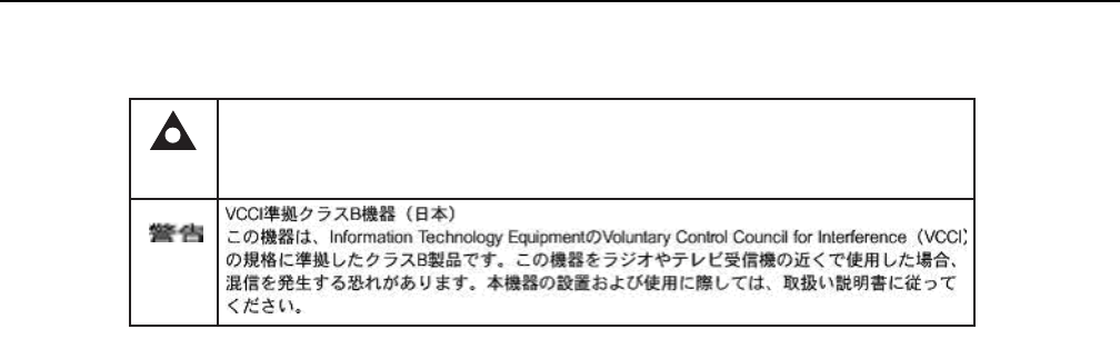
Figure 4 shows the PSE certification.
Caution 1 — Possibility of service interruption.
Caution 2 — Service interruption.
Note — Information of special interest.
Description Label text
ESD warning Caution: This assembly contains an electrostatic sensitive device.
Laser classification Class 1 laser product
PSE marking These power supplies are Japan PSE certified and compliant with
Japan VCCI emissions standards.
AP Product Guide ETSI safety guidelines
Issue: 01 DRAFT << doc part number is tbd >> 29
DRAFT
Figure 4 PSE certification
4.2 Safety standards compliance
This section describes the AP equipment compliance with the European safety
standards.
4.2.1 EMC, EMI, and ESD compliance
The AP equipment complies with the following EMC, EMI, and ESD requirements:
•EN 300-386 V1.5.1: Electromagnetic Compatibility and Radio Spectrum Matters
(ERM): Telecommunications Network Equipment; Electromagnetic Compatibility
(EMC) requirements; Electrostatic Discharge (ESD) requirements
•EN 55022 (2006): Class B, Information Technology Equipment, Radio
Disturbance Characteristics, limits and methods of measurement
•EN 55024 (2010): Information Technology Equipment, Immunity Characteristics,
limits and methods of measurement
•European Council Directive 2004/108/EC
•EN 300-386 V1.4.1: 2008
•EN 55022:2006 Class B
4.2.2 Equipment safety standard compliance
The AP equipment complies with the requirements of EN 60950-1, Safety of
Information Technology Equipment for use in a restricted location (per R-269).
This is a Class B product based on the standard of the Voluntary Control Council for Interference
from Information Technology Equipment (VCCI). If this is used near a radio or television receiver in
a domestic environment, it may cause radio interference. Install and use the equipment according
to the instruction manual.
Warning
19841

ETSI safety guidelines
30
AP Product Guide
<< doc part number is tbd >> Issue: 01 DRAFT
DRAFT
4.2.3 Environmental standard compliance
The AP equipment complies with the EN 300 019 European environmental
standards.
4.2.4 Laser product standard compliance
For most AP equipment, the AP complies with EN 60825-1 and IEC 60825-2 for laser
products. If there is an exception to this compliance regulation, you can find this
information in the standards compliance section of the unit data sheet in this Product
Guide.
4.2.5 Resistibility requirements compliance
The AP equipment complies with the requirements of ITU Recommendation K.21 for
resistibility of telecommunication equipment installed in customer premises to over
voltage and overcurrents. << does this apply to the AP? >>
4.2.6 Acoustic noise emission standard compliance
The AP equipment complies with EN 300 753 acoustic noise emission limit and test
methods.
4.3 Electrical safety guidelines
This section provides the electrical safety guidelines for the AP equipment.
Note 1 — The AP equipment complies with the U.S. National
Electrical Code. However, local electrical authorities have
jurisdiction when there are differences between the local and
U.S. standards.
Note 2 — The AP equipment complies with BS EN 61140.

AP Product Guide ETSI safety guidelines
Issue: 01 DRAFT << doc part number is tbd >> 31
DRAFT
4.3.1 Power supplies
The use of any non-Nokia approved power supplies or power adapters is not
supported or endorsed by Nokia. Such use will void any warranty or support contract
with Nokia. Such use greatly increases the danger of damage to equipment or
property.
4.3.2 Cabling
The following are the guidelines regarding cables used for the AP equipment:
•All cables must be approved by the relevant national electrical code.
•The cables for outdoor connection to the AP equipment must be suitable for
outdoor use.
• POTS wiring run outside the subscriber premises must comply with the
requirements of local electrical codes. In some markets, the maximum allowed
length of the outside run is 140 feet (43 m). If the outside run is longer, NEC
requires primary protection at both the exit and entry points for the wire. <<
remove this bullet since it refers to POTS ? >>
4.3.3 Protective earth
Earthing and bonding of the AP equipment must comply with the requirements of
local electrical codes.
4.4 ESD safety guidelines
The AP equipment is sensitive to ESD. Operations personnel must observe the
following ESD instructions when they handle the AP equipment.
During installation and maintenance, service personnel must wear wrist straps to
prevent damage caused by ESD.
Caution — This equipment is ESD sensitive. Proper ESD
protections should be used when you enter the TELCO Access
portion of AP equipment.
ETSI safety guidelines
32
AP Product Guide
<< doc part number is tbd >> Issue: 01 DRAFT
DRAFT
4.5 Laser safety guidelines
Observe the following instructions when you perform installation, operations, and
maintenance tasks on AP equipment.
Only qualified service personnel who are extremely familiar with laser radiation
hazards should install or remove the fiber optic cables and units in this system.
Observe the following danger for laser hazard. Eyes can be damaged when they are
exposed to a laser beam. Take necessary precautions before you plug in the optical
modules.
4.5.1 Laser classification
The AP equipment is classified as a Class 1 laser product based on its transmit
optical output.
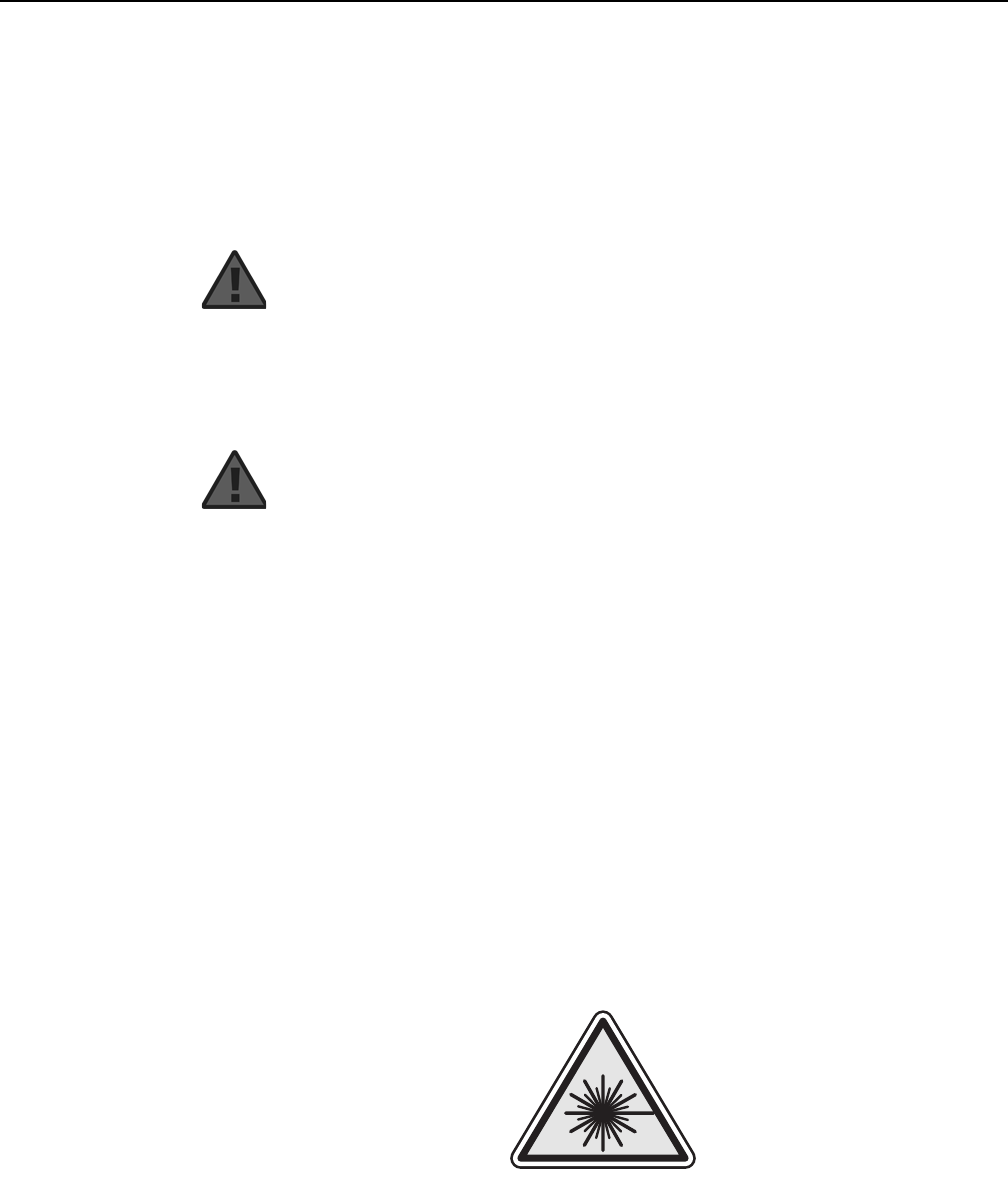
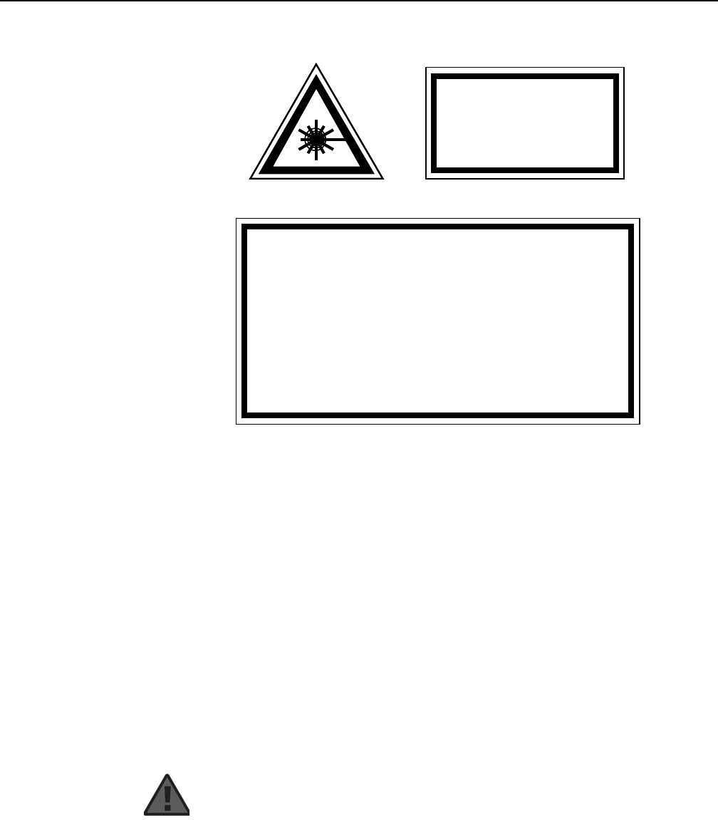
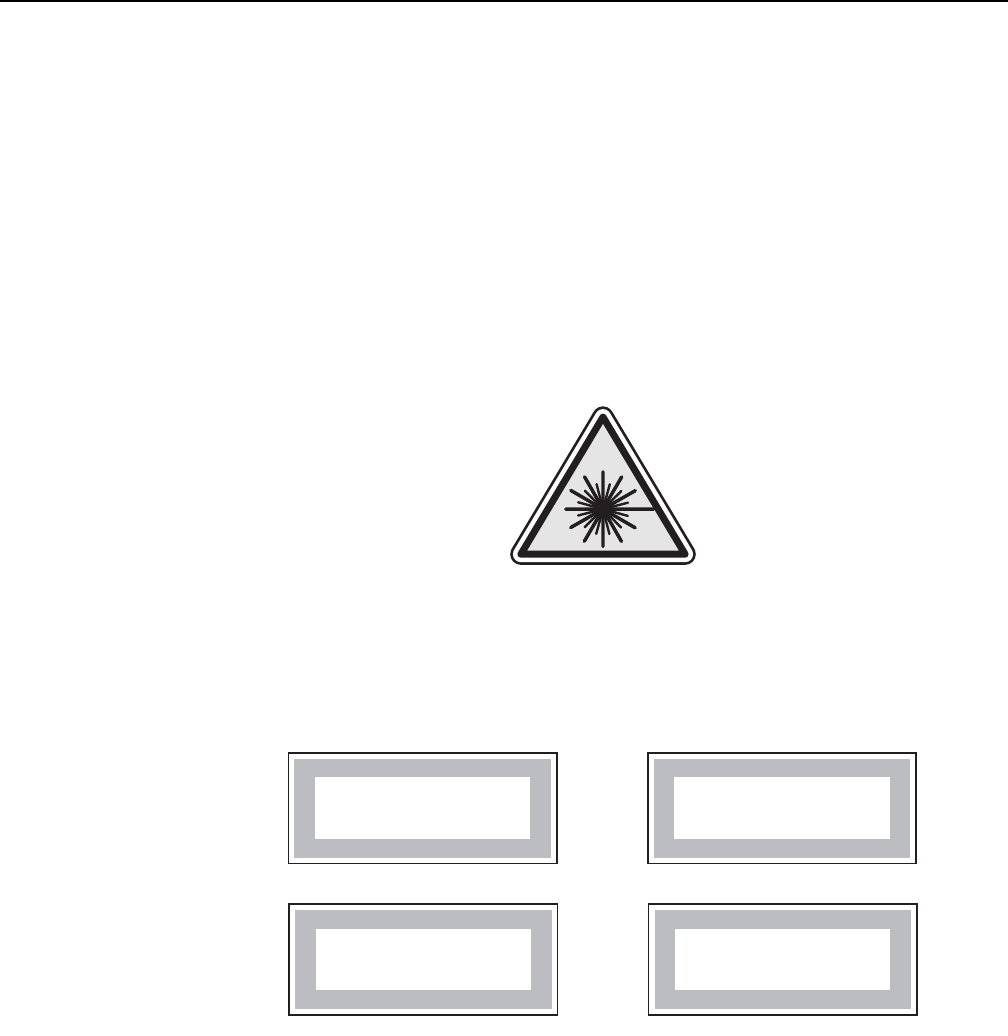
4.5.1.1 Laser warning labels
The following figures show the labels related to laser product, classification and
warning.
Figure 5 shows a laser product label.
Figure 5 Laser product label
Danger — There may be invisible laser radiation at the fiber
optic cable when the cable is removed from the connector.
Avoid direct exposure to the laser beam.
Danger — Possibility of equipment damage. Risk of eye
damage by laser radiation.
18455

AP Product Guide ETSI safety guidelines
Issue: 01 DRAFT << doc part number is tbd >> 33
DRAFT
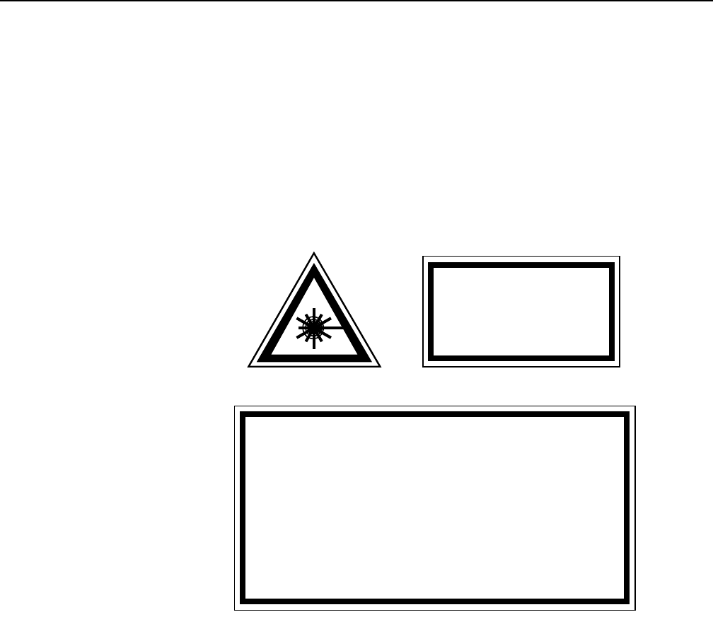
Figure 6 shows a laser classification label. Laser classification labels may be
provided in other languages.
Figure 6 Laser classification label
Figure 7 shows a laser warning label and an explanatory label for laser products.
Labels and warning may be provided in other languages. The explanatory label
provides the following information:
•a warning that calls attention to the invisible laser radiation
•an instruction against staring into the beam or viewing directly with optical
instruments
•wavelength
•normal output power
•maximum output power
LASER CLASSE 1CLASE 1 DEL LASER
CLASS 1 LASER PRODUCT PRODUCTO LASER CLASE 1
18992
'
'
ETSI safety guidelines
34
AP Product Guide
<< doc part number is tbd >> Issue: 01 DRAFT
DRAFT
Figure 7 Laser warning labels
4.5.2 Transmit optical output
The maximum transmit optical output of an AP is +5 dBm.
4.5.3 Normal laser operation
In normal operation, fiber cable laser radiation is always off until it receives signal.
Eyes can be damaged when they exposed to a laser beam. Operating personnel
must observe the instructions on the laser explanatory label before plugging in the
optical module.
INVISIBLE LASER RADIATION
DO NOT STARE INTO BEAM
OR VIEW DIRECTLY WITH
OPTICAL INSTRUMENTS
Wavelength(s): xxxx nm
Normal output power: xx m W
Max output power: yyy m W
Laser Warning Label Laser Warning Label
CLASS 1 LASER PRODUCT
INVISIBLE LASER RADIATION PRESENT AT FIBER OPTIC CABLE
WHEN NOT CONNECTED. AVOID DIRECT EXPOSURE TO BEAM.
RAYONNEMENT LASER CLASSE 1
RAYONNEMENT LASER INVISIBLE
EVITER TOUTE EXPOSITION AU FAISCEAU
NE PAS DEMONTER. FAIRE APPEL A UN PERSONNELL QUALIFIE
CLASE 1 DEL LASER
RADIACION DE LASER INVISIBLE. EVITAR CUALOUIER EXPOSICION AL
RAYO LASER. NO DESMONTAR. LLAMAR A PERSONAL AUTORIZADO
Laser Warning Label
18993
'
Danger — Risk of eye damage by laser radiation.

AP Product Guide ETSI safety guidelines
Issue: 01 DRAFT << doc part number is tbd >> 35
DRAFT
4.5.4 Location class
Use cable supports and guides to protect the receptacles from strain.
4.6 Environmental requirements
See section 7.6 in this guide for more information about temperature ranges.
During operation in the supported temperature range, condensation inside the AP
equipment caused by humidity is not an issue. To avoid condensation caused by
rapid changes in temperature and humidity, Nokia recommends:
•The door of the AP equipment not be opened until temperature inside and outside
the equipment has stabilized. << does the AP have a “door”? >>
•If the door of the AP equipment must be opened after a rapid change in
temperature or humidity, use a dry cloth to wipe down the metal interior to prevent
the risk of condensation.
•When high humidity is present, installation of a cover or tent over the AP
equipment helps prevent condensation when the door is opened.

ETSI safety guidelines
36
AP Product Guide
<< doc part number is tbd >> Issue: 01 DRAFT
DRAFT

AP Product Guide ANSI safety guidelines
Issue: 01 DRAFT << doc part number is tbd >> 37
DRAFT
5 ANSI safety guidelines
This chapter provides information about the mandatory regulations that govern the
installation and operation of the Access Points (APs) of the Nokia WPON solution in
the North American or ANSI market.
<< this chapter needs to be closely looked at to make sure that it only
provides applicable info for the AP and that no relevant AP info is
missing, as it was copied from a similar chapter in the G-241G-A
Product Guide >>
5.1 Safety instructions
This section describes the safety instructions that are provided in the AP customer
documentation and on the AP equipment.
5.1.1 Safety instruction boxes in customer
documentation
The safety instruction boxes are provided in the AP customer documentation.
Observe the instructions to meet safety requirements.
The following is an example of the Danger box.
The Danger box indicates that the described activity or situation may pose a threat
to personal safety. It calls attention to a situation or procedure which, if not correctly
performed or adhered to, may result in death or serious physical harm.
Do not proceed beyond a Danger box until the indicated conditions are fully
understood and met.
The following is an example of the Warning box.
Danger — Possibility of personal injury.
Warning 1 — Possibility of equipment damage.
Warning 2 — Possibility of data loss.
ANSI safety guidelines
38
AP Product Guide
<< doc part number is tbd >> Issue: 01 DRAFT
DRAFT
The Warning box indicates that the described activity or situation may, or will, cause
equipment damage, loss of data, or serious performance problems. It identifies a
possible equipment-damaging situation or provides essential information to avoid the
degradation of system operations or data.
Do not proceed beyond a warning until the indicated conditions are fully understood
and met.
The following is an example of the Caution box.
The Caution box indicates that the described activity or situation may, or will, cause
service interruption.
Do not proceed beyond a caution until the indicated conditions are fully understood
and met.
The following is an example of the Note box.
The Note box provides information that assists the personnel working with AP
equipment. It does not provide safety-related instructions.
5.1.2 Safety-related labels
The AP equipment is labeled with specific safety compliance information and
instructions that are related to a variant of the AP. Observe the instructions on the
safety labels.
Table 3 provides examples of the text in the various AP equipment safety labels. <<
some of the examples have “ONT” >>
Table 3 Safety labels
Caution 1 — Possibility of service interruption.
Caution 2 — Service interruption.
Note — Information of special interest.
Description Label text
UL compliance Communication service equipment US listed. Type 3R enclosure -
Rainproof.
TUV compliance Type 3R enclosure - Rainproof.
ESD warning Caution: This assembly contains electrostatic sensitive device.
(1 of 2)
AP Product Guide ANSI safety guidelines
Issue: 01 DRAFT << doc part number is tbd >> 39
DRAFT
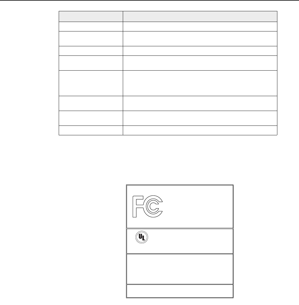
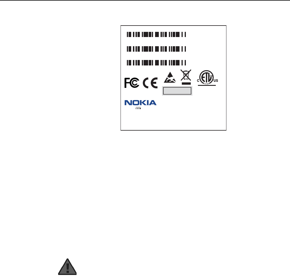
Figure 8 shows a sample safety label on the AP equipment. << will need a new
label, as the existing one shows “home or office use” >>
Figure 8 Sample safety label on the AP equipment
Laser classification Class 1 laser product
Laser product compliance This laser product conforms to all applicable standards of 21 CFR
1040.10 at date of manufacture.
FCC standards compliance Tested to comply with FCC standards for home or office use.
CDRH compliance Complies with 21 CFR 1040.10 and 1040.11 except for deviations
pursuant to Laser Notice No. 50, dated June 24, 2007
Operation conditions This device complies with Part 15 of the FCC Rules. Operation is
subject to the following two conditions: (1) this device may not cause
harmful interference, and (2) this device must accept any interference
received, including interference that may cause undesired operation.
Canadian standard
compliance (modular ONT) This Class A digital apparatus complies with Canadian ICES-003.
Canadian standard
compliance (outdoor ONT) This Class B digital apparatus complies with Canadian ICES-003.
CE marking There are various CE symbols for CE compliance.
Description Label text
(2 of 2)
18533
This device complies with Part 15 of the FCC Rules. Operation is subject
to the following two conditions: (1) this device may not cause harmful
interference, and (2) this device must accept any interference
received, including interference that may cause undesired operation.
This Class A digital apparatus complies with Canadian ICES-003. Cet appareil
numerique de la class A est conforme a la norme NMB-003 du Canada
Tested to Comply
with FCC Standards
FOR HOME OR OFFICE USE
COMMUNICATION SERVICE EQUIPMENT
US LISTED
27FY
Type 3R Enclosure - Rainproof
CAUTION
This Assembly Contains Electrostatic Sensitive Devices
c
®

ANSI safety guidelines
40
AP Product Guide
<< doc part number is tbd >> Issue: 01 DRAFT
DRAFT
5.2 Safety standards compliance
This section describes the AP equipment compliance with North American safety
standards.
5.2.1 EMC, EMI, and ESD standards compliance
The AP equipment complies with the following requirements:
•Federal Communications Commission (FCC) CFR 47, Part 15, Subpart B, Class
A requirements for << AP? >> equipment
•GR-1089-CORE requirements, including:
•Section 3 Electromagnetic Interference, Emissions Radiated and Conducted
•Section 3 Immunity, Radiated and Conducted
•Section 2 ESD Discharge Immunity: System Level Electrostatic Discharge and EFT
Immunity: Electrically Fast Transients
•ICES-003
•CAN/CSA C22.2 No. 60950-1
This equipment has been tested and found to comply with the limits for a Class B
digital device, pursuant to Part 15 of the FCC Rules. These limits are designed to
provide reasonable protection against harmful interference in a residential
installation. This equipment generates, uses and can radiate radio frequency energy
and, if not installed and used in accordance with the instructions, may cause harmful
interference to radio communications.
However, there is no guarantee that interference will not occur in a particular
installation. If this equipment does cause harmful interference to radio or television
reception, which can be determined by turning the equipment off and on, the user is
encouraged to try to correct the interference by one or more of the following
measures:
•Reorient or relocate the receiving antenna.
•Increase the separation between the equipment and receiver.
•Connect the equipment into an outlet on a circuit different from that to which the
receiver is needed.
•Consult the dealer or an experienced radio/TV technician for help.
Warning — Changes or modifications to this unit not expressly
approved by the party responsible for compliance could void
the user's authority to operate the equipment.

AP Product Guide ANSI safety guidelines
Issue: 01 DRAFT << doc part number is tbd >> 41
DRAFT
5.2.2 Equipment safety standard compliance
The AP equipment complies with the requirements of UL60950-1, Outdoor ONTs to
“Communication Service Equipment” (CSE) and Indoor ONTs to Information
Technology Equipment (ITE). << is “ONT” valid for both of these here? >>
5.2.3 Environmental standards compliance
The AP equipment complies with the following standards:
•GR-63-CORE (NEBS): requirements related to operating, storage, humidity,
altitude, earthquake, office vibration, transportation and handling, fire resistance
and spread, airborne contaminants, illumination, and acoustic noise
•GR-487-CORE: requirements related to rain, chemical, sand, and dust
•GR-487 R3-82: requirements related to condensation
•GR-3108: Requirements for Network Equipment in the Outside Plant (OSP)
•TP76200: Common Systems Equipment Interconnections Standards
5.2.4 Laser product standards compliance
The AP equipment complies with 21 CFR 1040.10 and CFR 1040.11, except for
deviations pursuant to Laser Notice No. 50, dated June 24, 2007” or to 21 CFR
1040.10 U.S. Center for Devices and Radiological Health (CDRH) of the Food and
Drug Administration (FDA) Laser Notice 42 for ONTs containing Class 1 Laser
modules certified by original manufactures. << is “ONT” okay here? >>
Per CDRH 21 CFR 10.40.10 (h) (1) (iv) distributors of Class 1 laser products, such
as Nokia AP equipment shall leave the following Laser Safety cautions with the end
user. << the AP is not installed at the end user’s site, so is this needed?
>>
a) “Class 1 Laser Product”
b) “Caution – Use of controls or adjustments or performance of procedures other
than those specified herein may result in hazardous radiation exposure.”
Figure 9 shows a laser product label.
ANSI safety guidelines
42
AP Product Guide
<< doc part number is tbd >> Issue: 01 DRAFT
DRAFT
Figure 9 Sample laser product label showing CDRH 21 CFR compliance
5.2.5 Resistibility requirements compliance
The AP equipment complies with the requirements of ITU Recommendation K.21 for
resistibility of telecommunication equipment installed in customer premises to
overvoltage and overcurrents. << does this apply to the AP? >>
5.3 Laser safety guidelines
Only qualified service personnel who are extremely familiar with laser radiation
hazards should install or remove the fiber optic cables and units in this system.
Observe the following warnings when you perform installation, operations, and
maintenance tasks on the AP equipment.
Observe the following danger for a laser hazard. Eyes can be damaged when they
are exposed to a laser beam. Take necessary precautions before you plug in the
optical modules.
Per CDRH 21 CFR 10.40.10 (h) (1) (iv) distributors of Class 1 laser products, such
as Nokia AP equipment shall leave the following Laser Safety cautions with the end
user. << the AP is not installed at the end user’s site, so is this needed?
>>
FiOS Enabled
To Order FiOS: 888 GET-FiOS
or visit Verizon.com
For Service: 888 553-1555
2301 Sugar Bush Rd.
Raleigh, NC 27612
No User Serviceable Parts Inside. Refer All Servicing To Qualified Personnel.
Complies with 21 CFR 1040.10 and
1040.11 except for deviations pursuant to
Laser Notice No. 50, dated June 24, 2007.
4P92
I.T.E 12VDC 2.5A
22813
Danger — There may be invisible laser radiation at the fiber
optic cable when the cable is removed from the connector.
Avoid direct exposure to beam.
Danger — Possibility of equipment damage. Risk of eye
damage by laser radiation.
AP Product Guide ANSI safety guidelines
Issue: 01 DRAFT << doc part number is tbd >> 43
DRAFT
a) “Class 1 Laser Product”
b) “Caution – Use of controls or adjustments or performance of procedures other
than those specified herein may result in hazardous radiation exposure.”
5.3.1 Laser warning labels
The following figures show sample labels related to laser product, classification and
warning.
Figure 10 shows a laser product label.
Figure 10 Laser product label
Figure 11 shows a laser classification label. Laser classification labels may be
provided in other languages.
Figure 11 Laser classification label
18455
LASER CLASSE 1CLASE 1 DEL LASER
CLASS 1 LASER PRODUCT PRODUCTO LASER CLASE 1
18992
'
'
ANSI safety guidelines
44
AP Product Guide
<< doc part number is tbd >> Issue: 01 DRAFT
DRAFT
Figure 12 shows a laser warning label and an explanatory label for laser products.
Explanatory labels may be provided in other languages. The explanatory label
provides the following information:
•a warning that calls attention to the invisible laser radiation
•an instruction against staring into the beam or viewing directly with optical
instruments
•wavelength
•normal output power
•maximum output power
Figure 12 Laser warning labels
5.3.2 Laser classification
The AP equipment is classified as a Class 1 laser product based on its transmit
optical output.
For Class 1 laser products, lasers are safe under reasonably foreseeable conditions
of operation, including the use of optical instruments for intrabeam viewing.
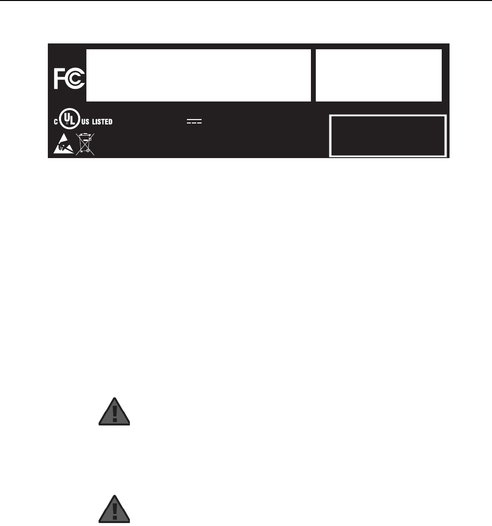
Figure 13 shows a sample laser product safety label on the AP equipment.
INVISIBLE LASER RADIATION
DO NOT STARE INTO BEAM
OR VIEW DIRECTLY WITH
OPTICAL INSTRUMENTS
Wavelength(s): xxxx nm
Normal output power: xx m W
Max output power: yyy m W
Laser Warning Label Laser Warning Label
CLASS 1 LASER PRODUCT
INVISIBLE LASER RADIATION PRESENT AT FIBER OPTIC CABLE
WHEN NOT CONNECTED. AVOID DIRECT EXPOSURE TO BEAM.
RAYONNEMENT LASER CLASSE 1
RAYONNEMENT LASER INVISIBLE
EVITER TOUTE EXPOSITION AU FAISCEAU
NE PAS DEMONTER. FAIRE APPEL A UN PERSONNELL QUALIFIE
CLASE 1 DEL LASER
RADIACION DE LASER INVISIBLE. EVITAR CUALOUIER EXPOSICION AL
RAYO LASER. NO DESMONTAR. LLAMAR A PERSONAL AUTORIZADO
Laser Warning Label
18993
'
AP Product Guide ANSI safety guidelines
Issue: 01 DRAFT << doc part number is tbd >> 45
DRAFT
Figure 13 Sample laser product safety label on the AP equipment
5.3.3 Transmit optical output
The maximum transmit optical output of an AP is +15.89 dBm.
5.3.4 Normal laser operation
In normal operation, fiber cable laser radiation is always off until it receives signal.
Operating personnel must observe the instructions on the laser explanatory label
before plugging in the optical module.
5.3.5 Location class
Use cable supports and guides to protect the receptacles from strain.
18532
3FE55851ABAA
Model:
MFG:
MONTH: XX
YEAR: XXXX
ICS: XX
MRev: XX
MAC:XXXXXXXXXXXX
SN:ALCLXXXXXXXX
FCC ID: XXXXXXXXXXX
This device complies with Part 15 of the FCC Rule.
Operation is subject to the following two conditions:
(1) This device may not cause harmful interference, and
(2) this device must accept any interference received,
including intereference that may cause undesired operation.
ASSEMBLED IN CHINA
2301 Sugar Bush Rd
.
Raleigh, NC 27612
DANGER - Invisible Laser radiation when open.
AVOID DIRECT EXPOSURE TO BEAM.
DANGER - Rayonnement Laser invisible lorsqu’elle
est ouverte. Evitee l’expostion direct au faisceau.
Complies with 21 CFR 1040.10 and 1040.11 except for deviations
pursuant to Laser Notice No. 50 dated June 24, 2007
12VDC 3A
I.T.E
Intertek
4006119
CLASS 1 LASER PRODUCT
PRODUIT LASER DE CLASSE 1
Danger — Risk of eye damage by laser radiation.

ANSI safety guidelines
46
AP Product Guide
<< doc part number is tbd >> Issue: 01 DRAFT
DRAFT
5.4 Electrical safety guidelines
This section provides the electrical safety guidelines for the AP equipment.
5.4.1 Power supplies
The use of any non-Nokia approved power supplies or power adapters is not
supported or endorsed by Nokia. Such use will void any warranty or support contract
with Nokia. Such use greatly increases the danger of damage to equipment or
property.
5.4.2 Cabling
The following are the guidelines regarding cables used for the AP equipment:
•Use only cables approved by the relevant national electrical code.
•Use cables suitable for outdoor use for connection to AP equipment.
•The AP equipment has been evaluated for use with external POTS wiring without
primary protection that may not exceed 140 ft (43 m) in reach. However, the power
cable must not exceed 100 ft (31 m). << remove this bullet since it refers to
POTS? >>
5.4.3 Protective earth
Earthing and bonding of the AP equipment must comply with the requirements of
NEC article 250 or local electrical codes.
Note — The AP equipment complies with the U.S. National
Electrical Code. However, local electrical authorities have
jurisdiction when there are differences between the local and
U.S. standards.

AP Product Guide ANSI safety guidelines
Issue: 01 DRAFT << doc part number is tbd >> 47
DRAFT
5.5 ESD safety guidelines
The AP equipment is sensitive to ESD. Operations personnel must observe the
following ESD instructions when they handle the AP equipment.
During installation and maintenance, service personnel must wear wrist straps to
prevent damage caused by ESD.
Nokia recommends that you prepare the site before you install the AP equipment. In
addition, you must control relative humidity, use static dissipating material for
furniture or flooring, and restrict the use of air conditioning.
5.6 Environmental requirements
See section 7.6 in this guide for temperature ranges for AP equipment.
During operation in the supported temperature range, condensation inside the AP
equipment caused by humidity is not an issue. To avoid condensation caused by
rapid changes in temperature and humidity, Nokia recommends:
•The door of the AP equipment not be opened until temperature inside and outside
the enclosure has stabilized.
•If the door of the AP equipment must be opened after a rapid change in
temperature or humidity, use a dry cloth to wipe down the metal interior to prevent
the risk of condensation.
•When high humidity is present, installation of a cover or tent over the AP
equipment helps prevent condensation when the door is opened.
Caution — This equipment is ESD sensitive. Proper ESD
protections should be used when entering the TELCO Access
portion of the AP equipment.

ANSI safety guidelines
48
AP Product Guide
<< doc part number is tbd >> Issue: 01 DRAFT
DRAFT

AP Product Guide WPON solution overview
Issue: 01 DRAFT << doc part number is tbd >> 49
DRAFT
6 WPON solution overview
6.2 WPON solution
6.3 WPON topologies
6.4 WPON architecture
6.5 WPON services
6.6 WPON management
6.7 WPON Solution standards compliance
6.8 Planning considerations/Use Cases
6.9 Solution-level technical specifications
6.10 Compatible CPE
6.1 << something to consider >>
<< This whole chapter (all 12+ pages of it) had been planned to also be
in the HOU Product Guide pretty much identical to how it is in the AP
Product Guide. However it has now been stripped down in the HOU
Product Guide, as keeping two almost identical chapters in the two
product guides is an invitation for them getting out of sync and as well
the AP as an entity is more of a WPON big picture kind of item and the
HOU as an entity is more of just a subscriber-type item that wirelessly
connects to an AP, so it makes sense to have the more detailed chapter
in the AP Product Guide and a less detailed chapter in the HOU Product
Guide. When looking that this chapter, we need to consider if the whole
chapter should also be in the HOU product guide, or if it is okay to have
a stripped down version in the HOU product guide that refers to this
chapter for more information about the WPON solution. >>

WPON solution overview
50
AP Product Guide
<< doc part number is tbd >> Issue: 01 DRAFT
DRAFT
6.2 WPON solution
The Nokia Wireless PON solution provides a 60 GHz wireless drop for PON or
P2P-based optic networks so that fiber optic cables are not used for connection to
subscribers’ homes. The WPON has an Access Point (AP) that physically connects
to the PON or P2P-based optic network. The AP uses 802.11ad for wireless
communication with up to six Home Outside Units (HOUs) that provide Gigabit
Ethernet connectivity to CPE inside subscribers homes.
<< do we need to provide more info about PONs and/or or P2P-based
optic networks? What exactly is a “P2P-based optic network” - does it
refer to GE, 2,5G, 10G Optical Ethernet? >> << there is quite a
difference between a PON, which is a “point to multipoint” network, and
a point to point network >> << can the PON be GPON, EPON, or other
types of PONs? >>
By using 802.11ad, the WPON solution offers limited interference between systems
because of narrow beams and inherent propagation limitations.
Figure 14 shows a high-level representation of the WPON solution providing a
wireless drop from a PON or P2P-based optic network to three subscriber homes.
Figure 14 High-level representation of the WPON solution
<< new figure to go here >>
The WPON solution can be used with a fiber distribution network that includes the
Nokia 7342 ISAM FTTU P-OLT as shown in Figure 15.
Figure 15 Example of three WPONs connected to a PON that uses a P-OLT
<< new figure that has three WPONs instead of the nine ONTs that are
in the “fiber distribution network” figure typically used in the OLT and
ONT documentation >>
6.2.1 APs and AP pairs
The AP provides the optical-to-wireless conversion for the WPON solution. The AP
can be installed on a utility pole or on the outside of a building and uses 802.11ad for
wireless line-of-sight communication with up to six HOUs up to 300 m away << or is
it 100m? >>. An AP contains a GPS and magnetometer, enabling it to report its
location and orientation to the management system. See chapter 7 in this guide for
detailed information about APs.
<< check distance in above paragraph >>

AP Product Guide WPON solution overview
Issue: 01 DRAFT << doc part number is tbd >> 51
DRAFT
Two APs can be installed as a pair on a utility pole to provide wider wireless
coverage, such as to HOUs on houses on both sides of a street, In this case the two
APs are known as an AP pair and they are connected to each other through a 2.5
Gigabit electrical Ethernet cable that handles all the traffic between the two APs. An
AP pair is considered to be a single AP, with one of APs of the pair serving as the
Main AP and the other AP as the Extension AP.
Figure 16 shows an AP pair, with each AP of the AP pair using 802.11ad for wireless
line-of-sight communication with three HOUs.
Figure 16 Example of an AP pair
<< new figure to go here >>
6.2.2 HOUs
An HOU provides the wireless-to-Gigabit Ethernet electrical conversion for the
WPON solution at the subscriber premises. Based on 802.11ad, an HOU can be
considered to be a wireless station (STA). An HOU is installed on the outside of a
subscriber’s home and uses a Gigabit Ethernet electrical cable for physical
connectivity to CPE such as a residential gateway inside the home. The same cable
is used to provide power over Ethernet to the HOU. An HOU contains a GPS and
magnetometer, enabling it to report its location and orientation to the management
system.
After physical installation and power up, an HOU automatically connects to the best
AP available, reports its presence, gets configured, and initiates service per the
customer subscribed service type. The HOU also detects any neighboring APs in its
line of sight and reports these to the management system.
See the HOU Product Guide for detailed information about HOUs.
6.2.3 WPONs
A PON or a P2P-based optic network can have multiple WPONs; for example, the
PON shown in Figure 15 has three WPONs.
At a minimum, a WPON consists of one AP and at least one HOU.
A WPON has a single NNI point at the optical connection point of the AP with the
PON or P2P-based optic network.
A WPON can have multiple UNI points, one at each HOU that is part of the WPON.
An OLT in the PON sees each WPON as a NNI; the OLT does not see the UNIs. In
this respect, a WPON is seen in a similar way as a subtending node, such as a DPU.
The number of APs and HOUs in a WPON depends on the topology used for the
WPON. See section 6.3 for more information about WPON topologies.

WPON solution overview
52
AP Product Guide
<< doc part number is tbd >> Issue: 01 DRAFT
DRAFT
6.2.4 Overhead cabling with composite cable
<< According to WPON product definition v12.pptx, there could be a
number of APs on poles that have overhead cabling with composite
cable. It is not exactly clear what is meant by “overhead cabling with
composite cable”, but assume that it is a cable that contains multiple
fiber optic cables coming from an optical distribution frame, with each
fiber optic cable to go to an AP that is not daisy chained (eg, if there are
five cables in the composite cable, then there are five APs, but note that
as per the PON model, each cable has traffic for all subscribers). If
assumption is correct, then “overhead cabling with composite cable” is
just a way for a fiber optic cable to get to an AP that is on a pole, and as
such does not need to be described and this section is not needed >>
6.3 WPON topologies
The WPON solution can be set up in the following topologies:
•basic WPON topology
•wireless daisy chain topology
•wireless mesh topology
<< is mesh supported in this release? >>
6.3.1 Basic WPON topology
The basic WPON topology consists of a single AP or AP pair that connects to the
PON or P2P-based optic network and provides wireless communications to HOUs
for which it can use 802.11ad for wireless line-of-sight communication. The topology
shown in Figure 14 is an example of the basic WPON topology. The network shown
in Figure 15 has three basic WPONs,
<< does the single AP or AP pair have “Head AP” as the device type in
the WPON manager GUI, or is “Head AP” only to be used for an AP that
has the fiber optic connection for a daisy chain (see next section)?
should we call a single AP or AP pair something like “standalone AP and
standalone AP pair” to distinguish them from Head AP and Relay AP of
daisy chains? >>
6.3.1.1 Resiliency of the basic WPON topology
<< should we use “redundancy” or “resiliency”? >>

AP Product Guide WPON solution overview
Issue: 01 DRAFT << doc part number is tbd >> 53
DRAFT
Resiliency is possible between two basic WPONs by having the WPONs provide
some resiliency for each other. HOUs have the ability to scan for the best AP and
automatically self-align to it. An HOU will automatically try re-associate with any other
AP in its reach if its active AP fails or the link with its active AP fails. From the WPON
that experienced the failure, the HOUs would be using an AP in a different WPON if
possible.
<< is this type of resiliency possible? >>
6.3.2 Wireless daisy chain topology
<< does WPON support linear and ring (looped) daisy chain topologies,
or just non-branched linear? >> << this section is written on the
assumption that only linear, non-branched non-looped daisy chains are
supported >>
<< what is the max number of “hops”? >>
A WPON can be set up in a linear, non-branched, non-looped daisy chain
configuration so that APs can use line-of-sight wireless communication with other
APs. In this case, one of the APs is connected to the PON or P2P-based optic
network and is known as the Head AP. The other APs in the daisy chain are known
as Relay APs. The fiber optical connection at the Head AP supports all the
subscribers that are served by all the APs in the daisy chain. Each AP in the daisy
chain automatically uses self backhaul so that all upstream traffic is transmitted to
the PON or P2P-based optic network through the Head AP.
The Head AP can use 802.11ad for wireless line-of-sight communication with one
downstream Relay AP and up to six HOUs. A Relay AP can use 802.11ad for
wireless line-of-sight communication with one upstream AP (which could be the
Head AP or another Relay AP), one downstream Relay AP, and up to six HOUs.
Figure 17 shows a daisy chain that has two Relay APs. Each of the APs in the
example has wireless communications with three HOUs.
Figure 17 Example of a daisy chain configuration
<< new figure to go here >>
If an AP pair is used in a daisy chain, only one of the APs in the AP pair functions as
an AP in the daisy chain, either as the Head AP or as a Relay AP. Figure 18 shows
an example of an AP pair in a daisy chain where one of the APs in the AP pair is a
Relay AP. The other AP in the AP pair is the Extension AP and it is not part of the
daisy chain.
Note — APs to be used in a daisy chain must be ordered from
Nokia for use as a Head AP or as Relay APs in a daisy chain.

WPON solution overview
54
AP Product Guide
<< doc part number is tbd >> Issue: 01 DRAFT
DRAFT
Figure 18 Example of a daisy chain configuration that has an AP pair
<< new figure to go here >>
6.3.2.1 Resiliency of the wireless daisy chain topology
Some resiliency within a linear, non-branched non-looped, daisy chain topology is
possible due to the ability of HOUs to scan for the best AP and automatically
self-align to it. An HOU will automatically try re-associate with another AP in its reach
if its active AP fails or the link with its active AP fails. This can provide resiliency within
the daisy chain for those HOUs that had been using a failed AP that can use an AP
that is upstream from the failed AP in the daisy chain.
<< should we add a figure to show this? >>
It is also possible to have resiliency between WPONs by having the WPONs provide
some resiliency for each other. HOUs have the ability to scan for the best AP and
automatically self-align to it. An HOU will automatically try re-associate with another
AP in its reach if its active AP fails or the link with its active AP fails. From the WPON
that experienced the failure, the HOUs would be using an AP in a different WPON if
possible.
<< is this type of resiliency possible? >> << should we add a figure that
has at least one daisy-chained WPON with HOUs that can access APs
in another WPON? >>
<< Branches in a daisy chain would make the topology more of a
“meshed” topology and it could be covered in the next section >>
6.3.3 Wireless mesh topology
<< is mesh topology supported in this release? if yes, need info - how
does it differ from branched daisy chain topologies? >>
6.4 WPON architecture
A WPON is made up:
•an underlay network
•one or more overlay networks

AP Product Guide WPON solution overview
Issue: 01 DRAFT << doc part number is tbd >> 55
DRAFT
<< the AC - FNMS-20579 - NAC: WPON Manager App phase 1 wiki
page has the above as two of four layers for “intents” for the WPON
manager; the additional layers are the Equipment Deployment layer
(responsible for provisioning the basis infrastructure like hardware
components, device management configurations, targeted software
version and uplink PON/P2P interfaces in-case of Head AP) as the top
layer and the Service/VLAN Layer (responsible for provisioning the
service related aspects like forwarders and sub vlan interfaces in Head
AP and HOU) as the bottom layer; do we need to cover these other two
layers, or are they already covered by the two layers that we have? >>
6.4.1 Underlay network
The underlay network serves as an IP-based network that provides connectivity
between all the APs and HOUs in the WPON. The underlay network uses RIP for
route distribution and routing for the APs and HOUs using IP addresses that are
assigned by a DHCP server hosted in the Head AP.
<< what if the WPON does not have a Head AP (that is, what if it is a
basic WPON topology that only has one AP?)? >>
A WPON has a single underlay network.
The underlay network is managed through the WPON manager. See section 6.6.1
for more information about the WPON manager.
6.4.2 Overlay network
The overlay network is a virtual network that provides L2 connectivity between an AP
and its associated HOUs through the use of GRE tunnels. The overlay network
provides logical P2P connectivity on top of the underlay network.
A WPON has an overlay network for each HOU in the WPON.
If an HOU is associated with an AP that is part of a basic WPON topology, the AP
and the HOU function as a Layer 2 switch with the AP being the NNI point and a GRE
tunnel endpoint and with the HOU being the UNI point and the other GRE tunnel
endpoint.
If an HOU is associated with an AP that is part of a daisy chain topology, the Head
AP and the HOU function as a Layer 2 switch with the Head AP being the NNI point
and one GRE tunnel endpoint and with the HOU being the UNI point and the other
GRE tunnel endpoint. The WPON solution behaves like a L2 network where Ethernet
frames are cross connected on a tagged VLAN basis between the NNI and UNI.

WPON solution overview
56
AP Product Guide
<< doc part number is tbd >> Issue: 01 DRAFT
DRAFT
A GRE tunnel serves as a VLAN that carries Ethernet frames both directions
between the HOU and AP. Each HOU has a private IP address and an X.509
certificate. The AP has a DHCP server to assign internal IP addresses, with each
wireless segment having its own subnet. In the AP, the remote IP address is
unspecified and learned dynamically, and each GRE tunnel in the WPON is assigned
a unique key. The DSCP field of the IP header of the GRE tunnel packets is used to
preserve QoS inside the WPON. The DSCP values match the TC to which the flow
carried inside is mapped. On the wireless interfaces, queue selection is done based
on the DSCP values.
<< is “TC” the same as traffic control? >>
For multicast traffic, an IGMP/MLD proxy is used in the AP to dynamically build the
multicast forwarding tree so that multicast traffic is passed to the GRE tunnels for
delivery to the HOUs.
In the downstream direction, the AP transmits only subscriber-specific traffic
(including multicast traffic) over the overlay network to each HOU (that is, it is the AP,
not the HOU, that discards traffic that is not intended for the subscriber associated
with each HOU).
In the upstream direction, APs use priority queues on a weighted fair queueing basis
to ensure that each HOU gets a fair share of the upstream bandwidth in the overlay
network.
Overlay networks, including GRE tunnels, are created and managed through the
WPON manager. See section 6.6.1 for more information about the WPON manager.
6.5 WPON services
<< placeholder as per the outline to provide a section on “Services
offered”, but it is not clear what info should be provided here even after
looking at some ONT documentation: the 7368 ISAM ONT Product
Overview (3FE-47159-AAAA-TCZZA) indicates voice, IP video, RF
video, and data as services; it has section 9.2 (System and service
capacity specifications) that has the following: “Service descriptions,
such as VoIP and flex services, are provided in the appropriate OLT
Product Information Manual” (which is presumably the product guide);
however the 7368 ISAM ONT O-210G-B O-211G-B Product Guide
(3FE-53082-AAAA-TCZZA) has no description of services - do we need
a section in the AP guide to describe these services, or perhaps this
section would be better in the HOU product guide? >>
<< the WPON manager can be used to configure “services” but it is at
the OLT, so perhaps we don’t need a section on WPON services >>
<< does “services” mean things like high speed Internet, voice over IP,
and broadcast TV? if yes, do they need to be included in this guide? >>

AP Product Guide WPON solution overview
Issue: 01 DRAFT << doc part number is tbd >> 57
DRAFT
6.6 WPON management
The following are used for management of the WPON solution:
•WPON manager (section 6.6.1)
•Nokia Altiplano (section 6.6.2)
•Bluetooth (section 6.6.3)
<< is the above list complete? >> << section 4.1 (Software architecture
Overview) of WPON TRS-20171228.docx (wPON Software Technical
Requirement Specification 3TG-00001-0002-DSZZA) indicates OAM
interface, NETCONF, SNMP, web, CLI, and Bluetooth and section 4.4
(Service Layer) has “6.Interface management External Interface
(OMA-DM/Confd/WebUI/CLI) -North-bound interface to wPON
Manager: Using Netconf/Yang for remote management -Local
interface: CLI for local configuration/debug/test -WEB CGI/UI: Not
mandatory for WPON >>
<< the WPON Feature Requirements doc indicates that until Altiplano
market introduction has be accomplished, the management solution
shall allow making use of the existing network management system,
AMS, to a certain extent - do we need to include AMS in this doc? >>
<< should this section have some overview info about software and
installation feature support, with a link to the section in the UDS that
covers software and installation feature support? >>
<< what about system management, software management,
performance management, fault management, hardware management,
security management, and troubleshooting (including trace and
debug)? >>

WPON solution overview
58
AP Product Guide
<< doc part number is tbd >> Issue: 01 DRAFT
DRAFT
6.6.1 WPON management through the WPON manager
The WPON manager provides web server management for the WPON solution. The
WPON manager allows you to configure the following:
•equipment deployment, specifically provisioning of the basic infrastructure such
as hardware components of APs and HOUs in a WPON, including device
management configurations, targeted software version, and the interface to the
PON or P2P optical network
•the underlay network of a WPON, specifically provisioning of the wireless and/or
Ethernet interfaces of APs and HOUs, including IP addresses and underlying
network routing aspects
•the overlay networks of a WPON, specifically provisioning of loopback interfaces,
provisioning GRE tunnels by creating GRE tunnel endpoints in the WPON, and
creating services on the OLT
<< what services? are “services” something that we need to cover in this
guide? >>
The WPON manager:
•provides abstractions for service provisioning across the various elements in a
WPON
•is responsible for monitoring the health of the various elements in a WPON as well
as monitoring the health of services provisioned on them
•is responsible for management of the GRE tunnels in a WPON
•is responsible for IP address assignment for the underlay network and
configuration of DHCP services in the Head AP for dynamic IP assignment for all
other elements in the WPON
•controls the entire QoS configuration
The WPON manager provides a GUI that provides the following:
•device list, with information such as name, type, connection status, alignment
status, and health for each AP and HOU in the WPON
•topology maps that can show network view, redundancy view, overlay view, or
street view of the WPON
•topology history that shows information such as topology version, timestamp, and
user name and allows you to view a graphical comparison of topology versions of
the WPON
•network list that provides the AP name, interface name, interface mode, IP
address, and subnet for each WPON
<< how do you access/invoke the WPON manager? >> << can we
indicate a document that the user can refer to for more info >>

AP Product Guide WPON solution overview
Issue: 01 DRAFT << doc part number is tbd >> 59
DRAFT
<< would changes be needed in this section if it turns out that the APs
and HOUs were “discovered” after they were installed rather than
having been provisioned? >>
When you create and provision APs and HOUs and create GRE tunnels and services
through the WPON manager, the information is passed to the Altiplano.
6.6.2 WPON management through the Nokia Altiplano
The Nokia Altiplano is a cloud-native access platform that consists of two products:
•the Nokia Altiplano Access Controller:
•The Access Controller is the domain controller for unified management of both SDN
and traditional access networks. It offers a wide range of APIs and tools, such as field
force, service fulfilment, service assurance and task center applications that help to
visualize, automate, optimize and enhance the network. It provides automation, easy
integration with the OSS/BSS and flexible programming of end-to-end services in the
access network.
•The Access Controller automates the network
•the Nokia Altiplano Access Virtualizer:
•The Access Virtualizer is the cloud component that creates a virtualized and
centralized view of the network in the cloud. It offers the logic and primitives for
efficiently programming and monitoring the underlying network elements, without
having to deal with challenges such as node reachability and scalability when
connecting to hundreds of thousands of nodes
•The Access Virtualizer programs nodes
The Nokia Altiplano Access Controller serves as the Element Manager for the WPON
solution by providing the following: << does the Altiplano Access Controller really
serve as the Element Manager, because it looks like the WPON manager does a lot
element management? >>
•PMA function for the APs and HOUs in each WPON, and acts as a PMA
aggregator (PMAA) towards the WPON manager << what is PMA? >>
•software management, backup and restore, and alarm collection functions
The Altiplano << Controller or Virtualizer? >> provisions APs and HOUs in response
to call-home messages sent by the APs and HOUs to it after they have been created
and provisioned through the WPON manager.
<< do we need to include anything about Netconf Server/CLI/SNMP
(Netconf server used in WPON is 3rd party commercial SW (confd
coming from tail-f), which provides CLI interface, SNMP interface and
netconf interface to NMS)? >>

WPON solution overview
60
AP Product Guide
<< doc part number is tbd >> Issue: 01 DRAFT
DRAFT
<< section 5.1.2 (Relay AP Start-up) of WPON TRS-20171228.docx
(wPON Software Technical Requirement Specification
3TG-00001-0002-DSZZA) indicates that the Operator manually installs
the Relay AP (report serial number of AP hardware to PMA); however
is it reported to the WPOM manager which then passes it to the
Altiplano (which provides the PMA function)? >> << the TRS does
not have this for the Head AP or HOU >>
<< do we need to say anything about installing or using the Altiplano?
can we indicate a document that the user can refer to for more info? >>
6.6.3 WPON management through Bluetooth
Local craft terminal access for APs and HOUs is provided through a Bluetooth
interface (classical Bluetooth, reach greater than 20 m) on the AP or HOU.
The Bluetooth interface provides access to a Bluetooth server that is used for local
management of the AP or HOU by a Bluetooth-equipped mobile phone or tablet or
other external device that can be used as a local terminal to access the AP or HOU
for on-site configuration or maintenance.
See section 11.2 in this product guide for information about using the Bluetooth
interface to configure an AP.
6.7 WPON Solution standards compliance
<< content needed; are there three (or more?) types of standards
compliance based on the type of connection: PON/P2P connectivity,
wireless connectivity, and CPE connectivity? >> << can we get info from
"3TG-00014-000x-xxZZA” docs (there are approx. 20 docs that appear
to have "spec/standards/safety guidelines-type" info or test results that
could perhaps go in the two product guides)? >>
6.8 Planning considerations/Use Cases
<< content needed >>
6.9 Solution-level technical specifications
<< content needed >> << overlap with AP and HOU UDSs? >>
Supported channels: Center frequency: channel 2: 60.48 GHz, channel 3: 62.64 GHz

AP Product Guide WPON solution overview
Issue: 01 DRAFT << doc part number is tbd >> 61
DRAFT
<< other specs as per 3TG-00011-AAAA-DDZZA-WPON Feature
Requirements >>
6.10 Compatible CPE
<< Include a table here, or in the CRN, that lists CPE that can connect
to the HOU? If here, should it be in the AP product guide as well as in
the HOU product guide? >>

WPON solution overview
62
AP Product Guide
<< doc part number is tbd >> Issue: 01 DRAFT
DRAFT

AP Product Guide AP unit data sheet
Issue: 01 DRAFT << doc part number is tbd >> 63
DRAFT
7 AP unit data sheet
7.1 AP part numbers and identification
7.2 AP general description
7.3 AP software and installation feature support
7.4 Subscriber traffic interfaces on the AP
7.5 AP LED information
7.6 AP specifications
7.7 GEM ports and T-CONTs
7.8 Performance monitoring statistics
7.9 Functional blocks
7.10 AP standards compliance
7.11 AP special considerations
7.1 AP part numbers and identification
Table 4 provides part numbers and identification information for the APs.

AP unit data sheet
64
AP Product Guide
<< doc part number is tbd >> Issue: 01 DRAFT
DRAFT
Table 4 AP part numbers and identification
Table 5 provides power supply ordering information for APs. For more information on
power supplies, see the 7368 ISAM ONT Power Supply and UPS Guide. << are
there any power supplies for the APs? If yes, are they in the 7368 ISAM
ONT Power Supply and UPS Guide and, if yes, would it be useful to
keep the reference to the 7368 ISAM ONT Power Supply and UPS
Guide? >> << does the AP only use mains AC connection, 110-230 VAC
for power? >>
Part number Provisioning
number Description CLEI CPR ECI/
Bar
code
3FE 47281 AA
<< confirm >> << need >> AP with one fiber optic connection and two 802.11ad
baseband units. One of the 802.11ad baseband units is
used for wireless connections to HOUs.
This AP can mounted on a wall or utility pole. The AP
can be used with an Extension AP if mounted on a utility
pole.
This is the only AP with a fiber optic connection and it is
designed to be used as a standalone AP (does not use
wireless connections to other APs) or as the Head AP in
a daisy chain topology (uses a wireless connection to a
downstream Relay AP).
The fiber optic connection is used to connect the AP to
a PON or P2P-based optic network that uses fiber optic
cabling that has an SC/APC adapter << confirm
adapter >>. The AP requires a protector module
and/or an SFP optical module << confirm >>
<< need >> <<
need
>>
<<
need
>>
3FE 47444 AA
<< confirm >> << need >> AP with three 802.11ad baseband units. One of the
802.11ad baseband units is used for wireless
connections to HOUs.
This AP can mounted on a wall or utility pole. The AP
can be used with an Extension AP if mounted on a utility
pole.
This AP is designed to be used as a Relay AP in a daisy
chain topology (supports a wireless connection to one
upstream AP, which could be the Head AP or another
Relay AP, and one downstream Relay AP).
This AP does not have any fiber optic connections and
cannot connect to a PON or P2P-based optic network.
<< need >> <<
need
>>
<<
need
>>
3FE 47289 AA
<< confirm >> << need >> AP with one 802.11ad baseband unit. The 802.11ad
baseband unit is used for wireless connections to
HOUs. This AP does not support wireless connections
to other APs.
This AP is designed to be used as the Extension AP in
an AP pair mounted on a utility pole. A 2.5G electrical
Ethernet cable is used to connect the APs in an AP pair.
This AP does not have any fiber optic connections and
cannot connect to a PON or P2P-based optic network.
<< need >> <<
need
>>
<<
need
>>
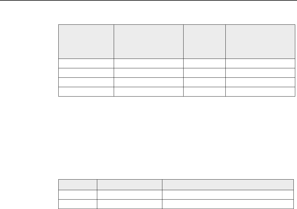
AP Product Guide AP unit data sheet
Issue: 01 DRAFT << doc part number is tbd >> 65
DRAFT
Table 5 AP power adapter and UPS power supplies
Note
(1) The list of detailed tests << need >>.
Table 6 provides accessory ordering information for APs. << are there any
accessories for the APs? what about connection cable for an AP pair,
pole-mounting hardware (strapping, fasteners, etc), wall-mounting
hardware (brackets, etc)? >>
Table 6 AP accessories
7.2 AP general description
APs are designed to provide the optical-to-wireless conversion for the WPON
solution by providing a fiber optic interface to the PON or P2P optical network along
with providing wireless line-of-sight communication with up to six HOUs or up to two
other APs. See section 6.2 for more information about the WPON solution.
On the optical side, the AP is compliant with ITU-T G.984 supporting 2.5Gbps
downstream and 1.25Gbps upstream line-rates. << note that these values do
not match the figure to be added in the WPON overview chapter >>
On the wireless side, the AP is compliant with 802.11ad supporting unlicensed
60 GHz mmWave wireless line-of-sight communication with 1 Gb/s peak speeds.
The AP is managed through the WPON manager and the Nokia Altiplano
cloud-native access platform. A local craft terminal access point is provided on the
AP through a Bluetooth interface (classical Bluetooth, reach greater than 20 m). See
section 6.6 in this guide for more information about management of the WPON
solution.
Power/UPS model Power UPS and cabling part
number information Customer
category or
country
compliance
tested for (1)
Notes
<< need >> << need >> << need >> << need >>
<< need >> << need >> << need >> << need >>
<< need >> << need >> << need >> << need >>
<< need >> << need >> << need >> << need >>
Accessory Orderable part number Notes
<< need >> << need >> << need >>
<< need >> << need >> << need >>

AP unit data sheet
66
AP Product Guide
<< doc part number is tbd >> Issue: 01 DRAFT
DRAFT
The AP provides the following functions and features:
•optical to wireless conversion
•<< in the downstream direction to the HOUs, does the AP simply
multicast the signal received from the upstream AP or fiber optic
connection to all its HOUs or does it only transmit subscriber-specific
traffic to each HOU (that is, is it the AP or HOU that discards traffic
that is not intended for the subscriber associated with the HOU?) >>
•can be installed on a utility pole (fits multiple pole dimensions and geometries) or
on the outside of a building
•daisy chain with other APs using self backhaul
•up to 3 Gbps aggregate capacity per HOU, supporting 1 Gbps peak speeds to up
to six HOUs up to 100 m << or is it 300 m >> away << confirm aggregate vs
peak values >>
•beam-forming antennas for fast and reliable wireless connection
•different antenna configurations and applications
•wide field of view for antennas: 180 degrees horizontal and 60 degrees vertical
•GPON or P2P optic fiber feed (SFP)
•single mode fiber (SC/APC connector)
•local grid or DC loop powered << or is it mains AC connection, 110-230
VAC for wall-mount and remote powering with multiple pairs carrying
high voltage/low current for pole mounted version only? >>
•sends dying gasp signal upstream if loss of power occurs
•has a built-in GPS and magnetometer
•fiber storage tray for wall mounting << confirm the AP has this >>
•robust design for harsh conditions (IP66)
•small size: 18 cm by 18 cm by 7 cm << or is it 25x16x7 cm? >>
•MDI/MDIX auto sensing << confirm the AP has this for its Ethernet
connection to another AP >>
•network demarcation for all services << confirm the AP does this >>
•interworking functions between the GEM and Ethernet layers << confirm the
AP does this >>
•mux and demux functions to the PON or P2P optical network<< confirm the AP
does this >>
•optics that support received signal strength indication (RSSI) << confirm the AP
has this >>
•G984.4 standard and revised compliant OMCI interface for management and
provisioning << confirm the AP has this >>
•on/off button << confirm the AP has this >>
•support for AIS with DOWN MEP << confirm the AP has this >>

AP Product Guide AP unit data sheet
Issue: 01 DRAFT << doc part number is tbd >> 67
DRAFT
7.3 AP software and installation feature support
Software for the AP is managed through the WPON manager and the Nokia
Altiplano; see section 6.6.1 for information about the WPON manager and section
6.6.2 for information about the Nokia Altiplano.
For information about installing or replacing an AP, see the following chapters:
•chapter 8 (Pre-installation steps for an AP or AP pair)
•chapter 9 (Procedures to install an AP or AP pair)
•chapter 10 (Procedures to replace an AP)
7.4 Subscriber traffic interfaces on the AP
Table 7 describes the supported subscriber traffic interfaces for the APs.
Table 7 AP subscriber traffic interfaces
Notes
(1) The Ethernet interface is only used for connecting two APs that make up an AP pair
(2) The wireless components are described in more detail in section 7.4.2
(3) There is a second wireless interface but it is not used in this application.
(4) The upstream AP can be a Rely AP or the Head AP.
AP application Head or
Relay AP Number of interfaces
PON/P2P optic
fiber Ethernet (1) Wireless (2)
AP used in a basic WPON
topology - One One One for drop to the HOUs (3)
AP used in a daisy chain
topology Head AP One One Two:
•one for drop to the HOUs
•one for daisy chaining to
the downstream AP
Relay AP - One Three:
•one for drop to the HOUs
•one for daisy chaining to
the upstream AP (4)
•one for daisy chaining to
the downstream AP
Extension AP used in an
AP pair (any topology) - - One One for drop to the HOUs

AP unit data sheet
68
AP Product Guide
<< doc part number is tbd >> Issue: 01 DRAFT
DRAFT
7.4.1 AP physical connections and components
Figure 19 shows the AP physical connections and components and section 7.4.2
describes the wireless components.
Figure 19 AP physical connections and components
<< add figure that has AP connections and components (if no
components, then change title of section and figure) >>
Table 8 describes the AP physical connections and components.
Table 8 AP physical connections and components
7.4.2 AP wireless components
Depending on the variant, the AP has wireless components for the following:
•drop to HOUs:
•one 802.11ad baseband unit that has three single-tile 32-antenna/RF arrays that
have a scan range of +/- 90° Azimuth, +30°+x /-30°+x elevation, antenna tiles tilted
upwards, angle x << need values for “x” >>
•the 32-antenna/RF arrays use vertical polarization and are located at the center line
of the AP
Connection or
component Description
PON/P2P fiber
optic connection This connection is provided through single mode fiber optic cable with an SC/APC
connector. << does the AP require an SFP? >>
Ethernet
connection This connection is provided through an RJ 25 connector. It is used for connecting two APs
in an AP pair to each other through a 2.5G electrical Ethernet cable.
Ground
connection << is there a ground point? >>
On/off button This button turns the AP on or off << is there an on/off button? >>
Reset button This button turns resets the AP << is there a reset; if yes is it a button with a
narrow hole? >>
Power
connection This connection is provided through a power cable with a << type? >>connector.

AP Product Guide AP unit data sheet
Issue: 01 DRAFT << doc part number is tbd >> 69
DRAFT
•daisy chaining to an upstream or downstream AP:
•two 802.11ad baseband units (one for upstream and the other for downstream)
•each 802.11ad baseband unit has a 64-antenna/RF array that is made up of two
32-antenna tiles and has a scan range of +/- 30° Azimuth, +/- 30° elevation, antenna
tiles are not tilted
•the 64-antenna/RF arrays use horizontal polarization and are located towards the left
and right sides of the AP
•for a wall-mounted AP, the antenna/RF arrays are angled 15° away from the wall
7.5 AP LED information
The AP has a single multifunction LED that is software-defined to light under certain
conditions.
Figure 20 shows the location of the LED.
Figure 20 AP LED location
<< add figure showing location of the LED>>
Table 9 describes the AP LED. << need info for AP LED >>
Table 9 AP LED behavior description
7.6 AP specifications
Table 10 lists the physical specifications for the AP. << are the specs the same
for all APs? >>
LED color and
behavior LED behavior description
Off <<
need >>
Solid green << need >>
Solid red << need >>
Flashing green (fast) << need >>
Flashing green (slow) << need >>
Flashing red (fast) << need >>
Flashing red (slow) << need >>
<< any other (eg
alternating red
and green)? >>
<< need >>

AP unit data sheet
70
AP Product Guide
<< doc part number is tbd >> Issue: 01 DRAFT
DRAFT
Table 10 AP physical specifications
Table 11 lists power consumption specifications for the AP.
Table 11 AP power consumption specifications
Table 12 lists the environmental requirements for the AP.<< need to verify >>
Table 12 AP environmental requirements
7.7 GEM ports and T-CONTs
<< this section is as per the G-241G-A ONT product guide - does any of
it apply to the APs? >>
Table 13 lists the maximum number of supported T-CONTs and GEM ports for
G-241G-A ONT. Not all ONTs will be supported in all of the releases indicated the
table. See the appropriate release Customer Release Notes for the most accurate
list of supported devices.
Dimensions Specifications
Height << need >>
Width << need >>
Depth << need >>
Weight [within 0.5 lb (0.23 kg)] << need >>
AP Maximum power
(not to exceed) Condition Minimum
power Condition
<< need >> << need >> << need >> << need >> << need >>
<< need >> << need >> << need >> << need >> << need >>
<< need >> << need >> << need >> << need >> << need >>
Mounting
method Temperature range and humidity Altitude
Utility pole or on
an outside wall Operating:
23F to 122F (-5C to 50C) ambient temperature
5% to 85% relative humidity, non-condensing
Maximum operating altitude is
10 000 ft (3048 m) above mean sea
level
Storage:
–40F to 140F (–40 to 60C)
5% to 93% relative humidity, non-condensing
Maximum non-operating altitude is
40 000 ft (12 192 m) above mean
sea level
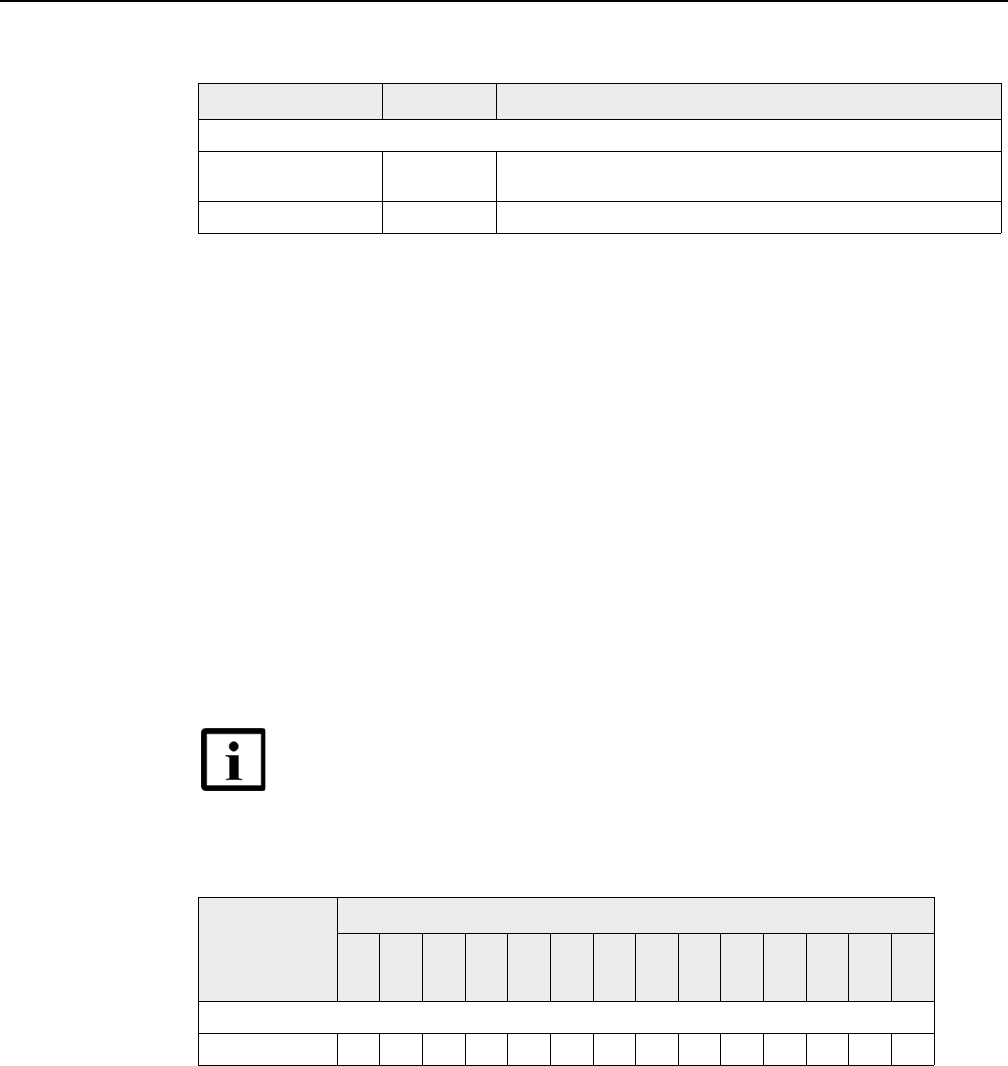
AP Product Guide AP unit data sheet
Issue: 01 DRAFT << doc part number is tbd >> 71
DRAFT
Table 13 G-241G-A ONT capacity for GEM ports and T-CONTs
7.8 Performance monitoring statistics
<< this section is as per the G-241G-A ONT product guide - does any of
it apply to the APs? >>
The following section identifies the supported performance monitoring statistics for
G-241G-A ONT. A check mark indicates the statistic is supported on that ONT. An
empty cell indicates the statistic is not supported. The following tables are
categorized by supported alarm types:
•Table 14 provides statistics for ONTENET type counters
•Table 15 provides statistics for ONTL2UNI type counters
•Table 16 provides statistics for PONONTTC, PONONTMCTC, PONONTTCHSI,
PONONTTCCES, PONONTTCFLOW, and PONONTTCVOIP type counters
•Table 17 provides statistics for PONONTTC aggregate type counters
Table 14 G-241G-A ONT ONTENET performance monitoring statistics
Note
(1) A 5 second polling window limitation exists on the ONT, therefore the margin of error for each 15-min window
is 5 seconds
ONT or MDU Maximum Notes
Package P ONTs
GEM ports per ONT 124 124 are present; 122 are available, and 2 are reserved for multicast
and debugging
T-CONTs per ONT 32 32 are present; 31 are available, and 1 is reserved for OMCI
Note — If you have trouble accessing G-241G-A ONT
performance monitoring statistics using TL1, please contact
your Nokia support representative for more information about
how to access and retrieve performance monitoring type
counters.
ONT ONTENET statistics
FCSE
EC
LC
RBO
SCF
MCF
DT
IMTE
CSE
AE
IMRE
FTL
TBO
SQE
GPON
G-241G-A (1) ✓✓✓✓✓✓✓✓✓✓✓✓✓✓
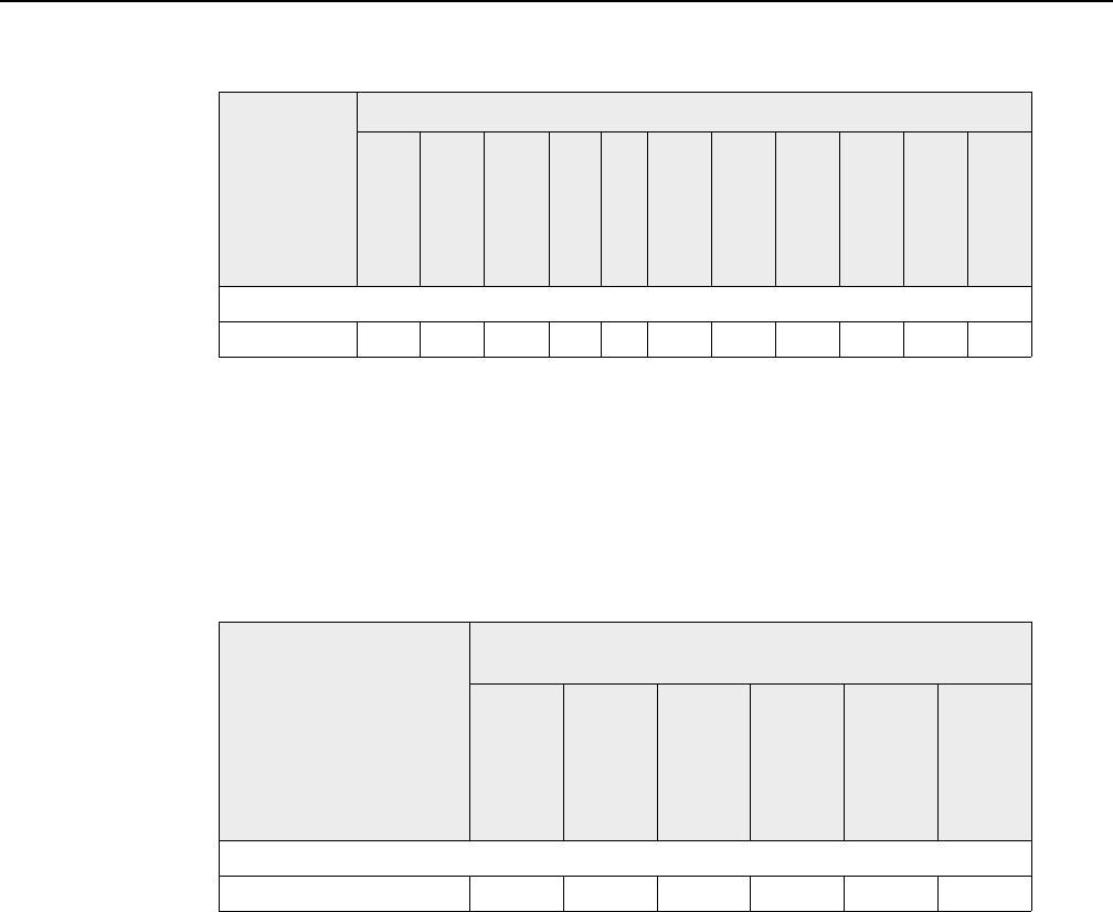
AP unit data sheet
72
AP Product Guide
<< doc part number is tbd >> Issue: 01 DRAFT
DRAFT
Table 15 G-241G-A ONT ONTL2UNI performance monitoring statistics
Note
(1) A 5 second polling window limitation exists on the ONT, therefore the margin of error for each 15-min window
is 5 seconds
Table 16 G-241G-A ONT PONONTTC, PONONTMCTC, PONONTTCHSI,
PONONTTCCES, PONONTTCFLOW, PONONTTCVOIP perfor-
mance monitoring statistics
Note
(1) A 5 second polling window limitation exists on the ONT, therefore the margin of error for each 15-min window
is 5 seconds
ONT ONTL2UNI statistics
FRAMES
BYTES
MCFRAMES
DSDRPDFRMS
USDRPDFRMS
USFRAMES
DSFRAMES
USBYTES
DSBYTES
USMCFRAMES
DSMCFRAMES
GPON
G-241G-A (1) ✓✓✓✓✓✓✓✓✓✓✓
ONT PONONTTC, PONONTMCTC, PONONTTCHSI, PONONTTCCES,
PONONTTCFLOW, PONONTTCVOIP statistics
TXBLOCKS
TXFRAGS
RXBLOCKS
RXFRAGS
LOSTFRAGS
BADGEMHDRS
GPON
G-241G-A (1) ✓✓✓✓✓

AP Product Guide AP unit data sheet
Issue: 01 DRAFT << doc part number is tbd >> 73
DRAFT
Table 17 G-241G-A ONT PONONTTC aggregate performance monitoring
statistics
Note
(1) A 5 second polling window limitation exists on the ONT, therefore the margin of error for each 15-min window
is 5 seconds
7.9 Functional blocks
Figure 21 shows the functional blocks for an AP. Note that not all functional blocks
are used in all APs:
•the AP used in a basic WPON topology does not use upstream and downstream
antenna/RF blocks
•a Head AP does not use the upstream antenna/RF block
•a Relay AP does not connect to a fiber optic cable
•an Expansion AP does not:
•use upstream and downstream antenna/RF blocks
•connect to a fiber optic cable
•the 2.5 G Ethernet block is only used if the AP is part of an AP pair
Figure 21 Functional blocks of an AP
<< add figure showing the functional blocks of an AP >>
Figure 22 shows the SoC functional block in more detail.
Figure 22 SOC functional block
<< add figure showing the SoC functional block >>
ONT PONONTTC (aggregate) statistics
TXBLOCKS
TXFRAGS
RXBLOCKS
RXFRAGS
LOSTFRAGS
BADGEMHDRS
GPON
G-241G-A (1) ✓✓✓✓✓

AP unit data sheet
74
AP Product Guide
<< doc part number is tbd >> Issue: 01 DRAFT
DRAFT
The SoC for the AP consists of the following key elements:
•GPON MAC:
The Gigabit Passive Optical Network Media Access Control (GPON MAC)
element on the SoC terminates the GPON interface using an optical diplexer. This
interface supports GPON as described in G.984.3 (GPON TC Layer) ITU
specification.
•Ethernet MAC:
The SoC provides up to four GE MACs. << confirm >>
•Control Processor:
The Control Processor features an integral memory management unit that
supports a dedicated 64 kbyte instruction cache and shares a single 32 kbyte data
cache with the DSP. The Control Processor and DSP also include a single
channel Data Management Application (DMA) controller with a 4 kbyte read
ahead low-latency Dynamic Random Access Memory (DRAM) access port. The
processors typically run at 400 MHz.
•Switch matrix:
The Switch matrix provides an integrated data channel between the four GE
MACs, the GPON MAC, the control processor, and the other integrated elements
such as flash memory, DRAM, and the local bus controller.
7.10 AP standards compliance
The APs are compliant with the following standards: << the following list is from
the G-241G-A ONT product guide - it needs to be reviewed carefully to
make sure that it is complete and accurate with respect to the APs >>
•EN-300019-2-1 (Class T1.2)
•EN-300019-2-2 (Class T2.3)
•EN-300019-2-3 (Class T3.2))
•ETL
•FCC (Class B)/CAN ICES-003
•IEEE 802.1p (QoS)
•IEEE 802.1q (VLANs)
•IEEE 802.3ab, 3i 3u (GE)
•IEEE 802.3 (2012) (auto-negotiation)
•IEEE 802.3x (flow control)
•MEF 2.0
•ITU-T G.984 (GPON interface framing)
•ITU-T G.984.2 (1.25 Gb/s, 2.5 Gb/s)
•ITU-T G.984.3 (activation with automatic discovery of a serial number and a
password)
•ITU-T G.984.4 (standard and revised) (OMCI interface for ONT management and
provisioning)
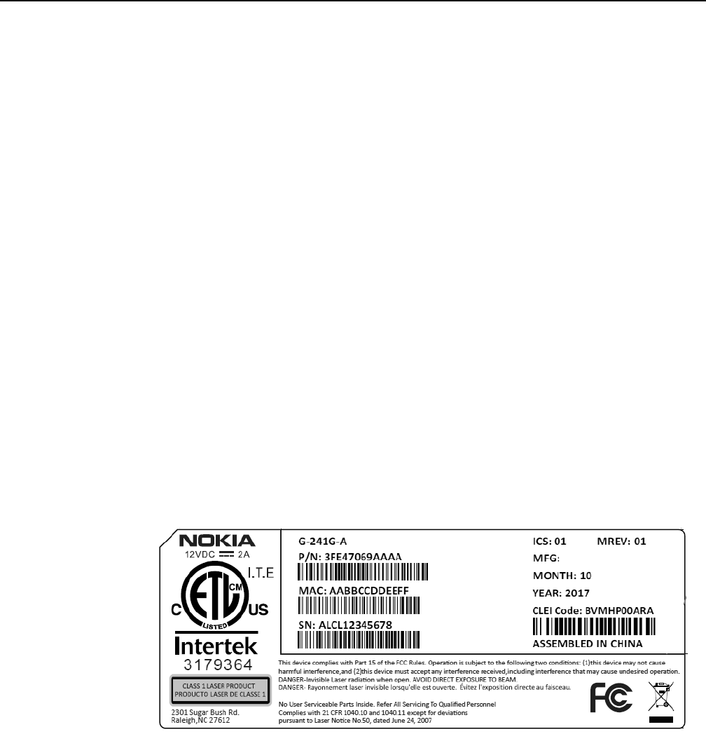
AP Product Guide AP unit data sheet
Issue: 01 DRAFT << doc part number is tbd >> 75
DRAFT
7.10.1 Energy-related products standby and off modes
compliance
<< this section needs to be confirmed >>
Hereby, Nokia declares that the APs are in compliance with the essential
requirements and other relevant provisions of Directive 2009/125/EC together with
Commission Regulation (EC) No 1275/2008 and Commission Regulation (EC) No
801/2013.
The APs qualify as equipment with high network availability (HiNA) functionality.
Since the main purpose of the APs is to provide network functionality with HiNA 7
days /24 hours, the modes Off/Standby, Power Management, and Networked
Standby are inappropriate.
For information about the type and number of network ports, see “Subscriber traffic
interfaces on the AP” in this chapter.
For information about power consumption, see “AP specifications” in this chapter.
7.10.2 Laser product standards compliance
<< this section needs to be confirmed and a new figure needs to be
provided that has the AP instead of the G-241G-A ONT >>
Figure 23 shows an AP laser product label. For information on laser product
maintenance, see chapter 13.
Figure 23 AP laser product label showing safety standard compliance
7.10.3 AP compliance statement
<< this section needs to be confirmed >>

AP unit data sheet
76
AP Product Guide
<< doc part number is tbd >> Issue: 01 DRAFT
DRAFT
This device complies with Part 15 of the FCC Rules. Operation is subject to the
following two conditions:
1 This device may not cause harmful interference.
2 This device must accept any interference received, including interference that
may cause undesired operation.
Warning: Changes or modifications to this unit not expressly approved by the party
responsible for compliance could void the user's authority to operate the equipment.
NOTE: This equipment has been tested and found to comply with the limits for a
Class B digital device, pursuant to Part 15 of the FCC Rules. These limits are
designed to provide reasonable protection against harmful interference in a
residential installation. This equipment generates, uses and can radiate radio
frequency energy and, if not installed and used in accordance with the instructions,
may cause harmful interference to radio communications.
However, there is no guarantee that interference will not occur in a particular
installation. If this equipment does cause harmful interference to radio or television
reception, which can be determined by turning the equipment off and on, the user is
encouraged to try to correct the interference by one or more of the following
measures:
•Reorient or relocate the receiving antenna.
•Increase the separation between the equipment and receiver.
•Connect the equipment into an outlet on a circuit different from that to which the
receiver is needed.
•Consult the dealer or an experienced radio/TV technician for help.
7.10.4 Responsible party
<< this section needs to be confirmed >>
<< if it is Raleigh, is the phone number and other info correct? >>
Table 18 lists the party in the US responsible for this AP.
Table 18 Responsible party contact information
Legal Company name Nokia USA Inc.
Address 2301 SUGAR BUSH RD. STE 300, RALEIGH,NC 27612
Phone, Fax +1 919 850 6127

AP Product Guide AP unit data sheet
Issue: 01 DRAFT << doc part number is tbd >> 77
DRAFT
7.11 AP special considerations
<< are there any special considerations and limitations for the APs? >>
<< the following table is for reference, as it is from the G-241G-A ONT
product guide >>
Table 19 G-241G-A ONT considerations and limitations
Considerations and limitations
Call History Data collection (ONTCALLHST) is supported, except for the following parameters:
RTP packets (discarded), far-end RTCP and RTCP-XR participation, RTCP average and peak round trip delay,
MOS, average jitter, number of jitter-buffer over-runs and under runs.
Some voice features are configurable on a per ONT basis, including Call Waiting, Call Hold, 3-Way Calling, and
Call Transfer.
The following voice features / GSIP parameters are configurable on a per-Client/ per-ONT basis (not
per-Subscriber):
•Enable Caller ID and Enable Caller Name ID
•Digitmap and the associated Interdigit and Critical timers and Enter key parameters
•Warmline timer is enabled per subscriber, but the warmline timer value is configured per ONT and must have
a lower value than the Permanent time
•Miscellaneous timers: Permanent, Timed-release, Reanswer, Error-tone, and CW-alert timers
•Features / functions: Message waiting mode, WMWI refresh interval, DTMF volume level
•Service Codes for the following features: CCW, Call Hold and Warmline

AP unit data sheet
78
AP Product Guide
<< doc part number is tbd >> Issue: 01 DRAFT
DRAFT

AP Product Guide Pre-installation steps for an AP or AP pair
Issue: 01 DRAFT << doc part number is tbd >> 79
DRAFT
8 Pre-installation steps for an AP or
AP pair
8.1 General
8.2 Scan the AP identifier
8.3 Create and provision the AP
8.4 HOU installation information
8.5 << placeholder in case needed >>
8.1 General
<< the purpose of this chapter is to cover installation-related items that should be
addressed at the CO or before the installer goes out to the installation site; Assume
that the PON and power for the AP are already set up and are available >>
<< briefly describe the various installation scenarios (such as installing
first AP (or a pair of APs) and one or more HOUs, adding an HOU to an
existing WPON provided by an AP, adding a Relay AP (and one or more
HOUs) to an existing WPON provided by an AP), and adding a second
AP (and one or more HOUs) to create an AP pair? Is it likely that an AP
would be installed by itself without at least one HOU being installed at
the same time? It certainly seems possible that just a single HOU could
be installed by itself for a "late uptake" customer. This could perhaps
be covered at a general level in the WPON Overview chapter, with any
specific info about the AP here, with a reference to the WPON Overview
chapter. >>
8.2 Scan the AP identifier
<< Scan the AP identifier, as the WPON (Wireless PON) wiki of Feb
06/18 indicates to do this before installing the AP or HOU (this reports
the serial number of the <<xx>> to the WPON manager) >> << need
details on how to do this >>
8.3 Create and provision the AP
<< Create and provision the AP, through the WPON manager, as the
WPON (Wireless PON) wiki of Feb 06/18 indicates to do this before
installing the AP or HOU >> << need details on how to do this >>

Pre-installation steps for an AP or AP pair
80
AP Product Guide
<< doc part number is tbd >> Issue: 01 DRAFT
DRAFT
8.4 HOU installation information
If you will be installing any HOUs while you are installing the AP or AP pair, refer to
the HOU Product Guide for information about HOUs, including pre-installation steps
and procedures on installing HOUs.
8.5 << placeholder in case needed >>
<< if needed, for any other pre-installation activities >>

AP Product Guide Procedures to install an AP or AP pair
Issue: 01 DRAFT << doc part number is tbd >> 81
DRAFT
9 Procedures to install an AP or AP
pair
9.1 Purpose
9.2 General
9.3 Prerequisites
9.4 Recommended tools
9.5 Safety information
9.6 Identify the mounting site
9.7 Make preparations at the mounting site
9.8 Mount the AP or AP pair and make connections
9.9 Complete the installation
9.1 Purpose
This chapter provides the procedures to install an AP or AP pair.
9.2 General
<< need to determine what should go here or if this section is even
needed >>
9.3 Prerequisites
You need the following items before beginning the installation:
•appropriate AP or APs
•a 2.5G electrical Ethernet cable if installing an AP pair
•a protector module and/or an SFP optical module if the AP is going to connect to
a PON or P2P-based optic network << confirm >>
•pole-mounting hardware (strapping, fasteners, etc) or wall-mounting brackets
•power supply and/or other “accessories”

Procedures to install an AP or AP pair
82
AP Product Guide
<< doc part number is tbd >> Issue: 01 DRAFT
DRAFT
•mobile phone or tablet for local management of the AP via Bluetooth
•<< anything else? >>
9.4 Recommended tools
You need the following tools for the installation:
•scanner for reading bar code on the AP
•something << what? >> for measuring distance << others?>> << note that
the rest of the items in the list are from the G-241G-A ONT Product
Guide and might not apply to an AP installation >>
•#2 Phillips screwdriver
•1/4 in. (6 mm) flat blade screwdriver
•wire strippers
•fiber optic splicing tools
•RJ-45 cable plug crimp tool
•voltmeter or multimeter
•optical power meter
•drill and drill bits
•pin-in-hex screwdriver
9.5 Safety information
Read the following safety information before beginning the installation
<< need to confirm that the info in this section applies to the AP, as it is
from the G-241G-A Product Guide >>
<< - include fiber optic safety info for AP
- include height/fall safety info
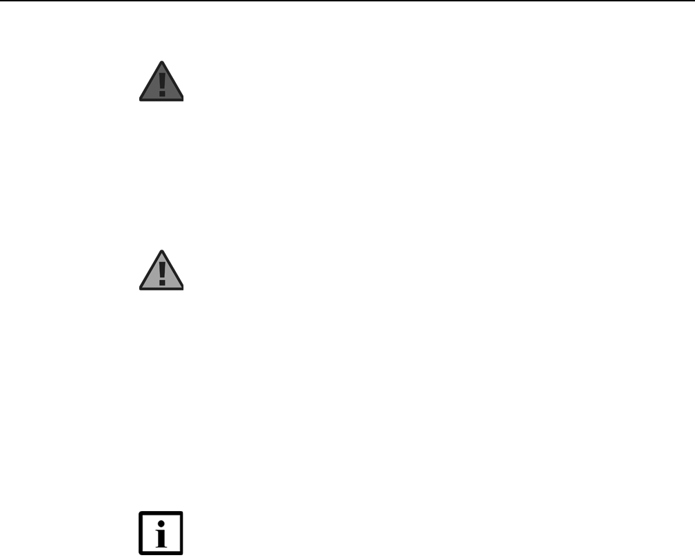
AP Product Guide Procedures to install an AP or AP pair
Issue: 01 DRAFT << doc part number is tbd >> 83
DRAFT
- include reference to chapter 11 for grounding safety >>
Danger 1 — Hazardous electrical voltages and currents can
cause serious physical harm or death. Always use insulated
tools and follow proper safety precautions when connecting or
disconnecting power circuits.
Danger 2 — Make sure all sources of power are turned off and
have no live voltages present on feed lines or terminals. Use a
voltmeter to measure for voltage before proceeding.
Danger 3 — Always contact the local utility company before
connecting the enclosure to the utilities.
Warning 1 — This equipment is ESD sensitive. Proper ESD
protections should be used when removing the fiber access
cover of the AP.
<< does the AP have an access cover? >>
Warning 2 — The intra-building port(s) of the equipment or
subassembly is suitable for connection to intra-building or
unexposed wiring or cabling only. The intra-building port(s) of
the equipment or subassembly MUST NOT be metallically
connected to interfaces that connect to the OSP or its wiring.
These interfaces are designed for use as intra-building
interfaces only (Type 2 or Type 4 ports as described in GR-
1089) and require isolation from the exposed OSP cabling. The
addition of Primary Protectors is not sufficient protection in
order to connect these interfaces metallically to OSP wiring.
Note 1 — Observe the local and national laws and regulations
that may be applicable to this installation.
Note 2 — The AP should be installed in accordance with the
applicable requirements of the NEC or CEC. Local authorities
and practices take precedent when there is conflict between the
local standard and the NEC or CEC.
Note 3 — The AP must be installed by qualified service
personnel.
Note 4 — See AP specifications in the AP unit data sheet for the
temperature ranges for the AP.

Procedures to install an AP or AP pair
84
AP Product Guide
<< doc part number is tbd >> Issue: 01 DRAFT
DRAFT
9.6 Identify the mounting site
<<intro needed >>
1Identify exact location on pole or wall for AP (or for AP pair on a pole); confirming that there
is line of sight and there is less than 100 m (or is it 300 m?) between the prospective AP
location and planned or installed HOU(s), and if the AP is to be part of a daisy chain, with the
planned or installed upstream or downstream AP (lines of sight will depend on the installation
scenario, covered in section 7.1) << need details >>
2STOP. This procedure is complete.
9.7 Make preparations at the mounting site
<< intro needed >>
1Make sure that you have the correct type of AP or APs:
•If you are installing an AP pair, one of the APs must be an Extension AP and you will need
to have a 2.5G electrical Ethernet cable to connect the two APs. The other AP must be a
Relay AP or an AP that can connect to a PON or P2P-based optic network.
•If you will be connecting the AP to a PON or P2P-based optic network, the AP must have
a fiber optic connection point
•If you are installing an AP in a daisy chain, and the AP is not connecting to the PON or
P2P-based optic network, the AP must be a Relay AP
•<< is it possible that they could be adding an Extension AP to an AP
already mounted on a pole? >>
2Scan the AP or AP pair if it was not done in section 7.2 (assuming that it is not too late if it
was not already scanned)? << need details >>
3Confirm power is available for the AP or AP pair << need details >>
4Prepare near-end of cables - does the AP require that the fiber optic cable have an SC/APC
adapter? If yes, then this step needs to cover that >> << use info from chapter 5 in the 7368
ISAM ONT Hardware and Cabling guide (far-end equipment and connections already done
as per section 7.1) << need details >>
5Verify optical signal levels at the near end of the PON or P2P-based optic networks – use
info from chapter 11 in the 7368 ISAM ONT Hardware and Cabling guide << need details
>>

AP Product Guide Procedures to install an AP or AP pair
Issue: 01 DRAFT << doc part number is tbd >> 85
DRAFT
6Do any pre-work on the AP/AP pair and/or pole/wall before mounting the AP/AP pair on the
pole/wall, esp since that actually mounting of the AP/AP pair could be high up and so it would
be good to do what can be done while on the ground (such as attaching a mounting plate to
an AP) or before mounting the AP/AP pair (such as attaching a bracket to the wall) in order
to minimize how many times the installer needs to go up the pole or on a ladder. << need
details >>
7STOP. This procedure is complete.
9.8 Mount the AP or AP pair and make
connections
<< need intro >> << Perhaps chapters 18 and 19 of the 7368 ISAM ONT Hardware
and Cabling guide might have useful info >>
1Mount the AP/AP pair << Will need to cover mounting AP or AP pair on a pole and mounting
an AP on an outside wall. If AP pair, note which AP is going to be the Head/Relay AP and
which AP is the Extension AP >> << need details >>
2Route and connect ground to the AP/AP pair << need details >> << perhaps use info from
chapter 6 in the 7368 ISAM ONT Hardware and Cabling guide >>
3If an AP pair, connect 2.5G electrical Ethernet cable between the two APs << need details
>>
4Route and connect power to the AP/AP pair << need details >> << perhaps use info from
chapter 6 in the 7368 ISAM ONT Hardware and Cabling guide >>
5If the AP is going to connect to the PON or P2P-based optic networks, route the fiber cable
to the AP and make the fiber optic connection << Place the fiber optic cable inside the
wall-mounted outdoor enclosure. Tie wrap the cable at the fiber optic strain relief if
necessary. >> << need details, but see below >> << is a protector module and/or an
SFP optical module needed? >> << include fiber optic warnings etc for the fiber optic
connection >>

Procedures to install an AP or AP pair
86
AP Product Guide
<< doc part number is tbd >> Issue: 01 DRAFT
DRAFT
<< the following is based on the G-241G-A ONT product guide >>
iRoute the fiber optic cable to the AP.
ii Loosen the lock screw on the connection clip of the fiber optic cable.
iii Lift up the connection clip.
iv Plug the SC/APC adapter of the fiber optic cable into the fiber optic connector located
on the AP, as shown in Figure << fig reference >>.
vLower the connection clip of fiber optic cable so that it secures the fiber optic cable.
vi Tighten the lock screw on the connection clip of the fiber optic cable.
6STOP. This procedure is complete.
9.9 Complete the installation
<< need intro >>
1Power up the AP by using the ON/OFF power switch. << add a figure showing location
of switch? >> If an AP pair, power up both APs << does it matter which one first? >>
2Verify the AP LED, voltage status, and optical signal levels << need details >> << are there
applicable details in the 7368 Hardware and Cabling Installation Guide that could be added
here? >>
3Verify system functionality of the AP << assume that this can be done via Bluetooth (used
with external app of mobile phone or tablet for local device management) >> << need
details >> << single AP vs AP pair >> << configure anything on the AP via Bluetooth >>
4If the HOU or HOUs for the AP have been installed, check that the AP has wireless
connectivity with the HOU or HOUs << need details >>
Danger — Fiber cables transmit invisible laser light. To avoid eye
damage or blindness, never look directly into fibers, connectors, or
adapters.
Warning — Be careful to maintain a bend radius of no less than 1.5
inches (3.8 cm) when connecting the fiber optic cable. Too small of a
bend radius in the cable can result in damage to the optic fiber.

AP Product Guide Procedures to install an AP or AP pair
Issue: 01 DRAFT << doc part number is tbd >> 87
DRAFT
5If the AP is to be part of a daisy chain and the upstream or downstream AP has been
installed, check that the AP has wireless connectivity with the upstream or downstream AP
<< need details >>
6If necessary, reset the AP. << can the AP be reset as described here? >>
iLocate the Reset button.
ii Insert the end of a straightened paper clip or other narrow object into the hole in the
Reset button to reset the AP.
7STOP. This procedure is complete.

Procedures to install an AP or AP pair
88
AP Product Guide
<< doc part number is tbd >> Issue: 01 DRAFT
DRAFT

AP Product Guide Procedures to replace an AP
Issue: 01 DRAFT << doc part number is tbd >> 89
DRAFT
10 Procedures to replace an AP
10.1 Purpose
10.2 General
10.3 Prerequisites
10.4 Recommended tools
10.5 Safety information
10.6 AP replacement procedure
10.1 Purpose
This chapter provides the procedures to replace an AP. << work on this chapter
after working on the installation chapter >>
<< will need to cover “replacing” a single AP on a pole with an AP pair -
or is it “installing? >>
10.2 General
<< is this section needed? >>
10.3 Prerequisites
<< work on this section after working on the installation chapter >>
10.4 Recommended tools
<< work on this chapter after working on the installation chapter >>
10.5 Safety information
<< work on this chapter after working on the installation chapter >>
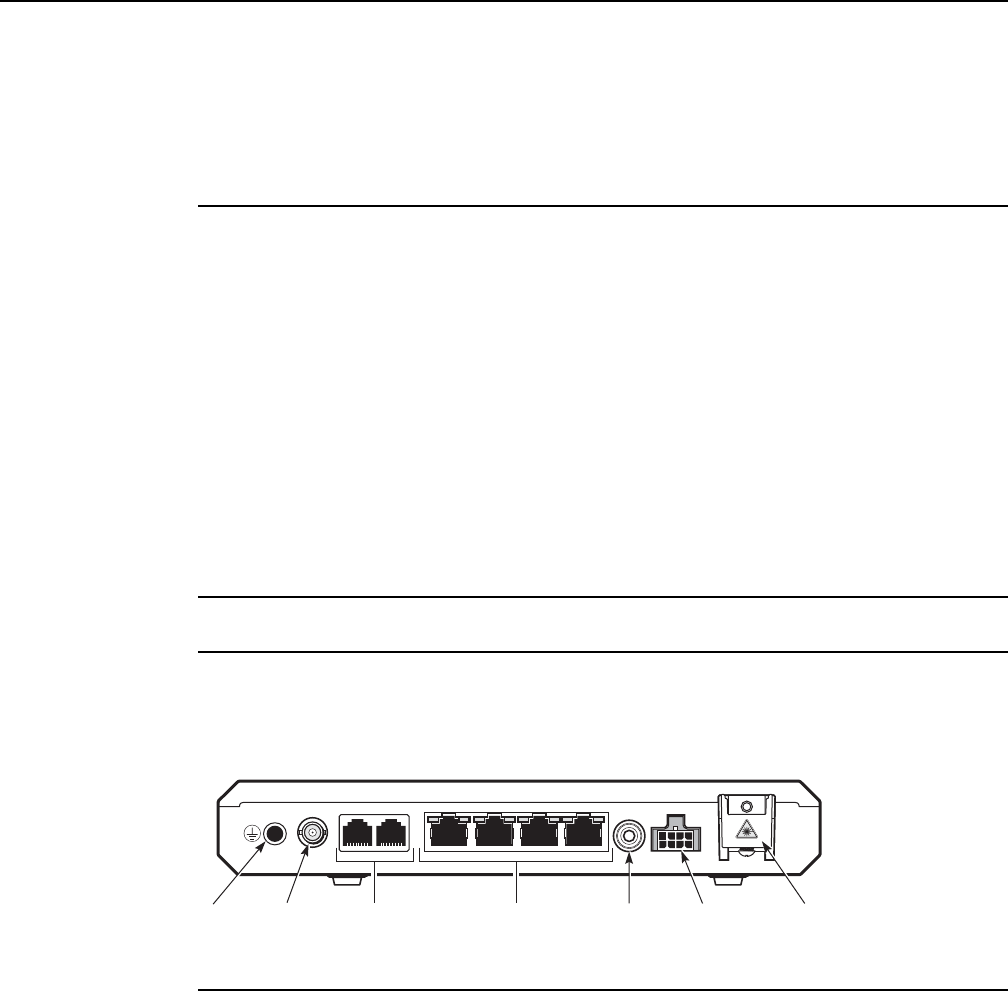
Procedures to replace an AP
90
AP Product Guide
<< doc part number is tbd >> Issue: 01 DRAFT
DRAFT
10.6 AP replacement procedure
<< work on AP replacement procedures after working on the AP installation
chapter >> << this procedure is currently the one for replacing the G-241G-A ONT
and is left here for use as a model for the AP >>
1Deactivate the ONT services at the P-OLT.
If you are using the SLID feature, this step is not required. The ONT and the services can
remain in service (IS).
iUse the RTRV-ONT command to verify the ONT status and the associated services.
Record the serial number or the SLID of the ONT displayed in the command output.
Example:
RTRV-ONT::ONT-1-1-1-1-1;
ii If the ONT is in service, place the ONT in OOS state.
Example:
ED-ONT::ONT-1-1-1-1-1;
2Power down the ONT unit by using the ON/OFF power switch.
3Disconnect the video, POTS, Ethernet, power, and ground cables from the ONT; see Figure
24.
Figure 24 G-241G-A ONT connections
4Unplug the SC/APC fiber optic cable from the ONT.
iLoosen the lock screw on the fiber optic connection clip.
ii Lift the connection clip up.
iii Unplug the fiber optic cable with SC/APC adapter from the fiber optic connector; see
Figure 24.
iv Lower the clip and tighten the lock screw.
DATA 1 DATA 2 DATA 3 DATA 4 ON/OFF POWER
POTS 1Video POTS 2
POTS ports
(RJ-14)
Gigabit Ethernet
ports (RJ-45)
On/off
button
Power
connector
SC/APC
connector
RF VideoGround lug
28061

AP Product Guide Procedures to replace an AP
Issue: 01 DRAFT << doc part number is tbd >> 91
DRAFT
5Replace the ONT with a new unit:
aOn a flat surface, such as a desk, substitute a replacement ONT for the old ONT; go to
step 8.
bOn a wall. The G-241G-A can be wall-mounted with or without a fiber storage tray.
iSlide the old ONT upward and then away from the two mounting screws until the
ONT is free of the wall.
ii Slide the wall mount keyholes on the ONT enclosure or fiber storage tray of the
replacement ONT down over the mounting screws until it is securely seated.
cIn a wall-mounted outdoor enclosure.
iUnfasten the G-241G-A ONT by turning the brackets to the open position and
remove the unit; see Figure 25.
Note — If the Emerson 24W AC/DC Power Adapter or the Delta
DUPS-1232GA will be used, the ONT must be mounted a minimum of
31.5 in (0.8 m) above the floor.
If the Delta DUPS-1232A will be used, the ONT must be mounted a
minimum of 59 in (1.5 m) above the floor.
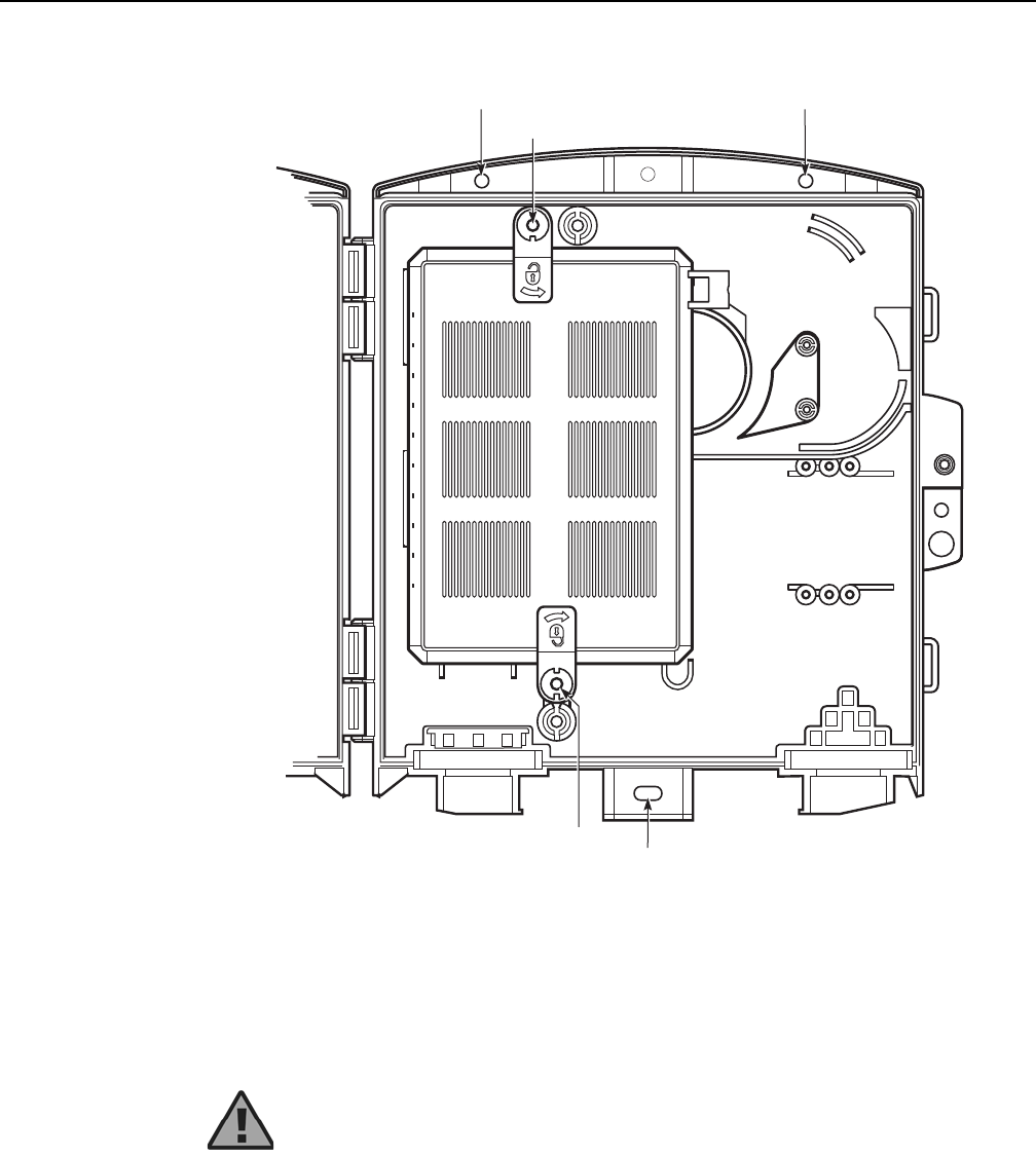
Procedures to replace an AP
92
AP Product Guide
<< doc part number is tbd >> Issue: 01 DRAFT
DRAFT
Figure 25 G-241G-A ONT mounted in an outdoor enclosure
ii Position the replacement G-241G-A ONT within the outdoor enclosure and
between the ONT brackets, as shown in Figure 25.
iii Secure the G-241G-A ONT by turning the brackets to the closed position.
Warning — Do not overtighten the ONT bracket when securing the
G-241G-A ONT to the outdoor enclosure. The unit can become skewed
and compromise the environmental seal of the ONT mounted in the
outdoor enclosure.
28068
Mounting hole
ONT bracket
ONT bracket
Mounting hole
Mounting hole
AP Product Guide Procedures to replace an AP
Issue: 01 DRAFT << doc part number is tbd >> 93
DRAFT
6To ground a G-241G-A ONT:
aAn indoor desktop or wall-mounted G-241G-A ONT is grounded by the 3-pin power
adapter or a grounded UPS.
bA G-241G-A ONT mounted in an outdoor enclosure must be grounded with a
permanent ground wire.
Connect a single #6 to #14 AWG ground wire to the recessed ground lug on the
G-241G-A ONT. The ground wire exits from the back of the ONT unit in the same way
as the cables.
7Connect the RF video coaxial cable; see Figure 24.
8Route up to four Ethernet cables to the RJ-45 ports, as shown in Figure 24. Connect the
Ethernet cables.
9Route up to two POTS cables to the RJ-14 ports, as shown in Figure 24. Connect the POTS
cables.
10 If required, have approved service personnel who are trained to work with optic fiber clean
the fiber optic connection. See the 7368 ISAM ONT Configuration, Management, and
Troubleshooting Guide for more information about fiber optic handling, inspection, and
cleaning.
Danger 1 — Hazardous electrical voltages and currents can cause
serious physical harm or death. Always use insulated tools and follow
proper safety precautions when connecting or disconnecting power
circuits. For more information on grounding safety, see chapter 12.
Danger 2 — Make sure all sources of power are turned off and have no
live voltages present on feed lines or terminals. Use a voltmeter to
measure for voltage before proceeding.
Danger 3 — Always contact the local utility company before connecting
the enclosure to the utilities.
Warning — Do not connect the ground lug of the G-241G-A ONT for
indoor installations; the ONT is grounded by the power adapter or UPS.
Danger — Fiber optic cables transmit invisible laser light. To avoid eye
damage or blindness, never look directly into fibers, connectors, or
adapters.
Procedures to replace an AP
94
AP Product Guide
<< doc part number is tbd >> Issue: 01 DRAFT
DRAFT
11 Connect the fiber optic cable to a G-241G-A ONT.
iRoute the fiber optic cable to the ONT.
ii Loosen the lock screw on the fiber optic connection clip.
iii Lift the connection clip up.
iv Plug the fiber optic cable with SC/APC adapter into the fiber optic connector; see Figure
24.
vLower the clip so that it secures the fiber optic cable.
vi Tighten the lock screw.
12 Install the power supply according to manufacturer specifications.
13 Connect the power cable with an 8-pin Molex connector or 3-pin power adapter to the ONT
unit.
14 For a G-241G-A ONT installed in an outdoor enclosure with an FSST, coil the excess cable
in a clockwise direction allowing it to exit the lower right cable exit port.
15 Power up the ONT unit by using the ON/OFF power switch.
Warning — Be careful to maintain a bend radius of no less than 1.5
inches (3.8 cm) when connecting the fiber optic cable. Too small of a
bend radius in the cable can result in damage to the optic fiber.
Warning — Units must be powered by a Listed or CE approved and
marked limited power source power supply with a minimum output rate of
12 V dc, 1.25 A.
Note — Observe the following:
•There must be approximately 18 in. (45.72 cm) of cable stub exiting
the FSST at the right cable exit point.
•The FSST stores a maximum of 75 ft (22.86 m) of cable.

AP Product Guide Procedures to replace an AP
Issue: 01 DRAFT << doc part number is tbd >> 95
DRAFT
16 If used, configure the SLID; see the 7368 ISAM ONT Configuration, Management, and
Troubleshooting Guide.
17 If necessary, reset the ONT.
iLocate the Reset button.
ii Insert the end of a straightened paper clip or other narrow object into the hole in the
Reset button to reset the ONT.
18 Verify the ONT LEDs, voltage status, and optical signal level; see the 7368 Hardware and
Cabling Installation Guide.
19 Activate and test the services; see the 7368 Hardware and Cabling Installation Guide.
20 For a G-241G-A ONT installed in an outdoor enclosure, close the access cover of the outdoor
enclosure and secure using the pin-in-hex screw.
21 STOP. This procedure is complete.
Note — A new SLID or the old SLID may be used with the replacement
ONT. If a new SLID is used, the new SLID must also be programmed at
the P-OLT using TL1 or a network manager. If the old SLID is used, no
changes need to be made at the P-OLT; see the operations and
maintenance documentation for the OLT for more details.

Procedures to replace an AP
96
AP Product Guide
<< doc part number is tbd >> Issue: 01 DRAFT
DRAFT

AP Product Guide Configure an AP
Issue: 01 DRAFT << doc part number is tbd >> 97
DRAFT
11 Configure an AP
11.1 Remote configuration
11.2 Local configuration
11.1 Remote configuration
The following can be used to configure an AP remotely:
•WPON manager (section 6.6.1)
•Nokia Altiplano (section 6.6.2)
11.2 Local configuration
Local craft terminal access for an AP is provided through a Bluetooth interface
(classical Bluetooth, reach greater than 20 m) on the AP.
The Bluetooth interface provides access to a Bluetooth server that can be used for
local management of the AP by a Bluetooth-equipped mobile phone or tablet or other
external device.
You can configure the following through the Bluetooth interface of an AP:
<< need info on how to configure APs through the Bluetooth interface >>

Configure an AP
98
AP Product Guide
<< doc part number is tbd >> Issue: 01 DRAFT
DRAFT
AP Product Guide Grounding safety
Issue: 01 DRAFT << doc part number is tbd >> 99
DRAFT
12 Grounding safety
12.1 Ground safety information
12.1 Ground safety information
<< this section is based on the equivalent section in the G-241-G-A ONT
product guide, with “ONT” changed to “AP” - the section needs to be
reviewed carefully to make sure that it is complete and accurate with
respect to the AP >>
Improper grounding can result in personal injury or equipment damage. See below
for specific dangers and considerations when handling grounding equipment.
Danger — Hazardous electrical voltages and currents can
cause serious physical harm or death. Always use insulated
tools and follow proper safety precautions when connecting or
disconnecting power circuits.
Danger — Make sure all sources of power are turned off and
have no live voltages present on feed lines or terminals. Use a
voltmeter to measure for voltage before proceeding.
Danger — Always contact the local utility company before
connecting the enclosure to the utilities.
Danger — You must connect the AP to earth ground before
connecting the power supply to the AP.
<< change “the power supply” to “power”? >>
Danger — The earth bonding terminal shall be connected to an
approved earth connection before the ac power is applied.
Grounding safety
100
AP Product Guide
<< doc part number is tbd >> Issue: 01 DRAFT
DRAFT
Danger — Earthing and bonding of the AP must comply with
the ANSI-specific requirements found in NEC Article 250.
•Insulation - The grounding conductor must be insulated and
listed as suitable for the purpose.
•Material - The grounding conductor shall be copper or other
corrosion-resistant conductive material stranded or solid.
•Size - The grounding conductor must be a minimum of
14 AWG per UL investigation. If local code or regulations
require more, follow per local codes or regulation.
•Length - The primary protector grounding conductor must be
as short as practicable. In one- and two-family dwellings, the
primary protector grounding conductor must be as short as
practicable, not to exceed 20 ft (6.0 m) in length.
•If the building or structure served has no grounding means,
as described in 800.100 (B)(1) or (B)(2)(1) of NEC
Article 250, the communications grounding conductor must
be connected to either of the following:
a) to any one of the individual electrodes described in 250.52
(A)(1), (A)(2), (A)(3), or (A)(4).
b) to an effectively grounded metal structure or to a ground
rod or pipe not less than 5 ft (1.5 m) in length and 1/ 2 in.
(12.7 mm) in diameter, driven, where practical, into
permanently damp earth, and the communications ground
rod shall be bonded to the power grounding electrode
system in accordance with 800.100 (D).
Warning — This equipment is ESD sensitive. Proper ESD
protection must be used when entering the TELCO Access
portion of the AP.
Warning — ANSI-specific: If using cable other than the
recommended brands, select only UL-listed cable, rated for the
specific installation.
Warning — ANSI-specific: If using cable other than the
recommended brands, select only UL-listed cable, rated for the
specific installation.
Note — Earthing and bonding of the AP must comply with the
ETSI-specific requirements found in local electrical wiring
codes.

AP Product Guide Grounding safety
Issue: 01 DRAFT << doc part number is tbd >> 101
DRAFT
Note — Observe all local and national laws and regulations
that may be applicable to this installation.

Grounding safety
102
AP Product Guide
<< doc part number is tbd >> Issue: 01 DRAFT
DRAFT

AP Product Guide Fiber optic maintenance
Issue: 01 DRAFT << doc part number is tbd >> 103
DRAFT
13 Fiber optic maintenance
13.1 Purpose
13.1 Purpose
<< create a chapter for the AP product guide based on chapter 13 of the
7368 ISAM ONT Hardware and Cabling guide
(3FE-47158-AAAA-TCZZA) >>
<< note that the HOU product guide does not need this chapter >>

Fiber optic maintenance
104
AP Product Guide
<< doc part number is tbd >> Issue: 01 DRAFT
DRAFT

AP Product Guide Fiber optic maintenance
Issue: 01 DRAFT << doc part number is tbd >> 105
DRAFT

Fiber optic maintenance
106
AP Product Guide
<< doc part number is tbd >> Issue: 01 DRAFT
DRAFT

Copyright 2018 Nokia.
<< doc part number is tbd >>
FCC Statement
Any Changes or modifications not expressly approved by the party responsible for compliance could void
the user’s authority to operate the equipment.
This device complies with part 15 of the FCC Rules. Operation is subject to the following two conditions:
(1) This device may not cause harmful interference, and
(2) This device must accept any interference received, including interference that may cause undesired
operation.
FCC Radiation Exposure Statement:
This equipment complies with FCC radiation exposure limits set forth for an uncontrolled
environment .This equipment should be installed and operated with minimum distance
25cm between the radiator& your body.
Note: This equipment has been tested and found to comply with the limits for a Class B digital
device, pursuant to part 15 of the FCC Rules. These limits are designed to provide reasonable
protection against harmful interference in a residential installation. This equipment generates, uses
and can radiate radio frequency energy and, if not installed and used in accordance with the
instructions, may cause harmful interference to radio communications. However, there is no
guarantee that interference will not occur in a particular installation. If this equipment does cause
harmful interference to radio or television reception, which can be determined by turning the
equipment off and on, the user is encouraged to try to correct the interference by one or more of
the following measures:
—Reorient or relocate the receiving antenna.
—Increase the separation between the equipment and receiver.
—Connect the equipment into an outlet on a circuit different from that to which the receiver is
connected.
—Consult the dealer or an experienced radio/TV technician for help.
it is not permitted to use the product on aircraft or satellites.