Nokia Bell A020WA WIFI Mesh User Manual 7368 ISAM CPE A 020W A Product Guide
Nokia Shanghai Bell Co. Ltd. WIFI Mesh 7368 ISAM CPE A 020W A Product Guide
Users Manual

Nokia — Proprietary and confidential
Use pursuant to applicable agreements
7368 Intelligent Services Access
Manager CPE
A-020W-A WiFi
7368 ISAM CPE A-020W-A Product Guide
3FE-47511-AAAA-TCZZA
Issue: 01
7368 ISAM CPE A-020W-A Product Guide
Release 05.08.01 | June 2018 | Edition 01

2
7368 ISAM CPE A-020W-A Product Guide
3FE-47511-AAAA-TCZZA Issue: 01
Nokia is a registered trademark of Nokia Corporation. Other products and company
names mentioned herein may be trademarks or tradenames of their respective
owners.
The information presented is subject to change without notice. No responsibility is
assumed for inaccuracies contained herein.
© 2018 Nokia.
Contains proprietary/trade secret information which is the property of Nokia and must
not be made available to, or copied or used by anyone outside Nokia without its
written authorization. Not to be used or disclosed except in accordance with
applicable agreements.
Release 05.08.01 | June 2018 | Edition 01

7368 ISAM CPE A-020W-A Product Guide Preface
Issue: 01 3FE-47511-AAAA-TCZZA 9
1Preface
This preface provides general information about the documentation set for CPEs.
1.1 Scope
This documentation set provides information about safety, features and functionality,
ordering, hardware installation and maintenance, and software installation
procedures for the current release.
1.2 Audience
This documentation set is intended for planners, administrators, operators, and
maintenance personnel involved in installing, upgrading, or maintaining the CPEs.
1.3 Required knowledge
The reader must be familiar with general telecommunications principles.
1.4 Acronyms and initialisms
The expansions and optional descriptions of most acronyms and initialisms appear
in the glossary (3FE-47157-AAAA-TCZZA).
1.5 Assistance and ordering phone numbers
Nokia provides global technical support through regional call centers. Phone
numbers for the regional call centers are available at the following URL:
http://support.alcatel-lucent.com. If this link does not work, copy and paste it directly
into your web browser.
For ordering information, contact your Nokia sales representative.
Release 05.08.01 | June 2018 | Edition 01

Preface
10
7368 ISAM CPE A-020W-A Product Guide
3FE-47511-AAAA-TCZZA Issue: 01
1.6 Nokia quality processes
Nokia’s CPE quality practices are in compliance with TL 9000 requirements. These
requirements are documented in the Fixed Networks Quality Manual
3FQ-30146-6000-QRZZA. The quality practices adequately ensure that technical
requirements and customer end-point requirements are met. The customer or its
representatives may be allowed to perform on-site quality surveillance audits, as
agreed upon during contract negotiations
1.7 Safety information
For safety information, see the appropriate safety guidelines chapter.
1.8 Documents
Documents are available using ALED or OLCS.
Procedure 1 To download a ZIP file package of the customer documentation
1Navigate to http://support.alcatel-lucent.com and enter your user name and password. If you
are a new user and require access to this service, please contact your Nokia sales
representative.
2From the Technical Content for drop-down menu, choose the product.
3Click on Downloads: Electronic Delivery.
4Choose Documentation from the drop-down menu and click Next.
5Select the image from the drop-down menu and click Next.
6Follow the on-screen directions to download the file.
Release 05.08.01 | June 2018 | Edition 01
7368 ISAM CPE A-020W-A Product Guide Preface
Issue: 01 3FE-47511-AAAA-TCZZA 11
Procedure 2 To access individual documents
Individual PDFs of customer documents are also accessible through the Nokia Customer Support
website.
1Navigate to http://support.alcatel-lucent.com and enter your user name and password. If you
are a new user and require access to this service, please contact your Nokia sales
representative.
2From the Technical Content for drop-down menu, choose the product.
3Click on Manuals and Guides to display a list of customer documents by title and part
number. You can filter this list using the Release drop-down menu.
4Click on the PDF to open or save the file.
1.9 Special information
The following are examples of how special information is presented in this document.
Danger — Danger indicates that the described activity or
situation may result in serious personal injury or death; for
example, high voltage or electric shock hazards.
Warning — Warning indicates that the described activity or
situation may, or will, cause equipment damage or serious
performance problems.
Caution — Caution indicates that the described activity or
situation may, or will, cause service interruption.
Note — A note provides information that is, or may be, of
special interest.
Release 05.08.01 | June 2018 | Edition 01

Preface
12
7368 ISAM CPE A-020W-A Product Guide
3FE-47511-AAAA-TCZZA Issue: 01
1.9.1 Procedures with options or substeps
When there are options in a procedure, they are identified by letters. When there are
required substeps in a procedure, they are identified by roman numerals.
Procedure 3 Example of options in a procedure
At step 1, you can choose option a or b. At step 2, you must do what the step indicates.
1This step offers two options. You must choose one of the following:
aThis is one option.
bThis is another option.
2You must perform this step.
Procedure 4 Example of required substeps in a procedure
At step 1, you must perform a series of substeps within a step. At step 2, you must do what the
step indicates.
1This step has a series of substeps that you must perform to complete the step. You must
perform the following substeps:
iThis is the first substep.
ii This is the second substep.
iii This is the third substep.
2 You must perform this step.
Release 05.08.01 | June 2018 | Edition 01

7368 ISAM CPE A-020W-A Product Guide Preface
Issue: 01 3FE-47511-AAAA-TCZZA 13
1.10 Multiple PDF document search
You can use Adobe Reader Release 6.0 and later to search multiple PDF files for a
common term. Adobe Reader displays the results in a single display panel. The
results are grouped by PDF file, and you can expand the entry for each file.
Procedure 5 To search multiple PDF files for a common term
1Open Adobe Acrobat Reader.
2Choose Edit→Search from the Acrobat Reader main menu. The Search PDF panel appears.
3Enter the search criteria.
4Click on the All PDF Documents In radio button.
5Select the folder in which to search using the drop-down menu.
6Click on the Search button.
Acrobat Reader displays the search results. You can expand the entries for each document
by clicking on the + symbol.
Note — The PDF files in which you search must be in the same
folder.
Release 05.08.01 | June 2018 | Edition 01

Preface
14
7368 ISAM CPE A-020W-A Product Guide
3FE-47511-AAAA-TCZZA Issue: 01
Release 05.08.01 | June 2018 | Edition 01

7368 ISAM CPE A-020W-A Product Guide
Issue: 01 3FE-47511-AAAA-TCZZA 3
Table of contents
1 Preface.............................................................................................9
1.1 Scope ..........................................................................................................9
1.2 Audience......................................................................................................9
1.3 Required knowledge....................................................................................9
1.4 Acronyms and initialisms .............................................................................9
1.5 Assistance and ordering phone numbers ....................................................9
1.6 Nokia quality processes.............................................................................10
1.7 Safety information......................................................................................10
1.8 Documents ................................................................................................10
1.9 Special information ....................................................................................11
1.9.1 Procedures with options or substeps.........................................................12
1.10 Multiple PDF document search .................................................................13
2 ANSI safety guidelines ...................................................................9
2.1 Safety instructions .......................................................................................9
2.1.1 Safety instruction boxes in customer documentation ..................................9
2.1.2 Safety-related labels..................................................................................10
2.2 Safety standards compliance ....................................................................11
2.2.1 Responsible party......................................................................................11
2.2.2 Energy-related products standby and off modes compliance....................12
2.2.3 FCC statement ..........................................................................................12
2.2.4 FCC Radiation Exposure Statement .........................................................13
2.2.5 Resistibility requirements compliance .......................................................13
2.3 Electrical safety guidelines ........................................................................13
2.3.1 Power supplies ..........................................................................................14
2.3.2 Cabling ......................................................................................................14
3 ETSI safety guidelines..................................................................15
3.1 Safety instructions .....................................................................................15
3.1.1 Safety instruction boxes ............................................................................15
3.1.2 Safety-related labels..................................................................................16
3.2 Safety standards compliance ....................................................................17
3.2.1 Responsible party......................................................................................17
3.2.2 Energy-related products standby and off modes compliance....................18
3.2.3 EMC and RED compliance........................................................................18
3.2.4 Equipment safety standard compliance.....................................................18
3.2.5 Environmental standard compliance .........................................................19
3.2.6 Resistibility requirements compliance .......................................................19
3.3 Electrical safety guidelines ........................................................................19
3.3.1 Power supplies ..........................................................................................19
3.3.2 Cabling ......................................................................................................19
4 ETSI environmental guidelines ...................................................21
4.1 Environmental requirements......................................................................21
4.1.1 Transportation ...........................................................................................21
4.1.2 EU RoHS ...................................................................................................21
4.1.3 End-of-life collection and treatment ...........................................................22
Release 05.08.01 | June 2018 | Edition 01

4
7368 ISAM CPE A-020W-A Product Guide
3FE-47511-AAAA-TCZZA Issue: 01
5 A-020W-A unit data sheet ............................................................23
5.1 A-020W-A part numbers and identification................................................23
5.2 A-020W-A general description...................................................................24
5.2.1 TR-069 object support for WiFi parameters ..............................................26
5.2.2 Independent TR69 session with SaaS ......................................................26
5.2.3 TR69 authentication using TLS and CA certificates ..................................26
5.3 A-020W-A software and installation feature support .................................27
5.4 A-020W-A interfaces and interface capacity .............................................27
5.4.1 A-020W-A connections and components ..................................................27
5.5 A-020W-A LEDs ........................................................................................28
5.6 A-020W-A detailed specifications..............................................................30
5.7 A-020W-A functional blocks ......................................................................30
5.8 A-020W-A standards compliance ..............................................................31
5.9 A-020W-A special considerations..............................................................31
5.9.1 WiFi service ...............................................................................................32
5.9.1.1 WiFi standards and certifications...............................................................32
5.9.1.2 WiFi GUI features ......................................................................................32
5.9.2 A-020W-A considerations and limitations..................................................32
6 Install a A-020W-A ........................................................................33
6.1 Purpose .....................................................................................................33
6.2 General......................................................................................................33
6.3 Prerequisites..............................................................................................33
6.4 Recommended tools..................................................................................33
6.5 Safety information......................................................................................34
6.6 Procedure ..................................................................................................35
7 Replace a A-020W-A .....................................................................37
7.1 Purpose .....................................................................................................37
7.2 General......................................................................................................37
7.3 Prerequisites..............................................................................................37
7.4 Recommended tools..................................................................................37
7.5 Safety information......................................................................................38
7.6 Procedure ..................................................................................................39
8 Configure a A-020W-A..................................................................41
8.1 GUI configuration.......................................................................................41
8.1.1 Login..........................................................................................................41
8.1.2 Device and connection status....................................................................42
8.1.3 Network configuration................................................................................53
8.1.4 Security configuration ................................................................................71
8.1.5 Application configuration ...........................................................................82
8.1.6 Maintenance ..............................................................................................88
8.1.7 RG troubleshooting counters.....................................................................98
Release 05.08.01 | June 2018 | Edition 01

7368 ISAM CPE A-020W-A Product Guide
Issue: 01 3FE-47511-AAAA-TCZZA 5
List of figures
2 ANSI safety guidelines ...................................................................9
Figure 1 A-020W-A sample safety label ..................................................................11
3 ETSI safety guidelines..................................................................15
Figure 2 A-020W-A sample safety label ..................................................................17
4 ETSI environmental guidelines ...................................................21
Figure 3 Recycling/take back/disposal of product symbol .......................................22
5 A-020W-A unit data sheet ............................................................23
Figure 4 A-020W-A CPE..........................................................................................25
Figure 5 A-020W-A physical connections................................................................28
Figure 6 A-020W-A LEDs ........................................................................................29
Figure 7 Single-residence WiFi CPE with Gigabit Ethernet.....................................31
6 Install a A-020W-A ........................................................................33
Figure 8 A-020W-A connections..............................................................................35
7 Replace a A-020W-A .....................................................................37
Figure 9 A-020W-A connections..............................................................................39
8 Configure a A-020W-A..................................................................41
Figure 10 Web login window......................................................................................42
Figure 11 Device Information window........................................................................43
Figure 12 LAN status window ....................................................................................45
Figure 13 WAN Status window ..................................................................................47
Figure 14 WAN Status IPv6 window..........................................................................49
Figure 15 Home Networking information window ......................................................51
Figure 16 Statistics window (LAN port statistics shown) ...........................................53
Figure 17 LAN settings window .................................................................................54
Figure 18 LAN IPv6 network window.........................................................................56
Figure 19 WAN window .............................................................................................58
Figure 20 WAN DHCP window ..................................................................................59
Figure 21 Wireless (2.4GHz) network window...........................................................61
Figure 22 Wireless (5GHz) network window..............................................................63
Figure 23 Wireless Schedule window........................................................................65
Figure 24 DNS network window ................................................................................66
Figure 25 TR-069 network window ............................................................................68
Figure 26 QoS Config window (L2)............................................................................69
Figure 27 QoS Config window (L3)............................................................................70
Figure 28 Firewall window .........................................................................................72
Figure 29 MAC filter window......................................................................................74
Figure 30 IP filter window ..........................................................................................76
Figure 31 URL Filter window .....................................................................................77
Figure 32 Parental Control window............................................................................78
Figure 33 DMZ and ALG window...............................................................................80
Figure 34 Access Control window .............................................................................81
Figure 35 Port forwarding window .............................................................................83
Release 05.08.01 | June 2018 | Edition 01

6
7368 ISAM CPE A-020W-A Product Guide
3FE-47511-AAAA-TCZZA Issue: 01
Figure 36 Port Triggering window..............................................................................84
Figure 37 DDNS window ...........................................................................................86
Figure 38 NTP window ..............................................................................................87
Figure 39 UPnP and DLNA window...........................................................................88
Figure 40 Password window......................................................................................90
Figure 41 Device Management window.....................................................................91
Figure 42 Backup and Restore window .....................................................................92
Figure 43 Firmware Upgrade window........................................................................93
Figure 44 Reboot Device window ..............................................................................94
Figure 45 Factory Default window .............................................................................95
Figure 46 Diagnostics window ...................................................................................96
Figure 47 Log window................................................................................................97
Figure 48 RG Troubleshooting Counters window......................................................99
Release 05.08.01 | June 2018 | Edition 01

7368 ISAM CPE A-020W-A Product Guide
Issue: 01 3FE-47511-AAAA-TCZZA 7
List of tables
2 ANSI safety guidelines ...................................................................9
Table 1 Safety labels ..............................................................................................10
Table 2 Responsible party contact information ......................................................11
3 ETSI safety guidelines..................................................................15
Table 3 Safety labels ..............................................................................................16
Table 4 Responsible party contact information ......................................................17
5 A-020W-A unit data sheet ............................................................23
Table 5 Identification of A-020W-A.........................................................................23
Table 6 A-020W-A interface connection capacity...................................................27
Table 7 A-020W-A physical connections................................................................28
Table 8 A-020W-A LEDs ........................................................................................29
Table 9 A-020W-A physical specifications .............................................................30
Table 10 A-020W-A power consumption specifications ...........................................30
Table 11 A-020W-A environmental specifications....................................................30
8 Configure a A-020W-A..................................................................41
Table 12 Device Information parameters .................................................................43
Table 13 LAN status parameters..............................................................................46
Table 14 WAN Status parameters............................................................................47
Table 15 WAN status IPv6 parameters ....................................................................49
Table 16 Home Networking parameters...................................................................51
Table 17 LAN parameters ........................................................................................54
Table 18 LAN IPv6 network parameters...................................................................56
Table 19 WAN parameters .......................................................................................58
Table 20 WAN DHCP parameters............................................................................60
Table 21 Wireless 2.4GHz network parameters.......................................................61
Table 22 Wireless 5GHz network parameters..........................................................64
Table 23 DNS network parameters ..........................................................................67
Table 24 TR-069 network parameters......................................................................68
Table 25 QoS Config parameters.............................................................................71
Table 26 Firewall parameters ...................................................................................73
Table 27 MAC filter parameters................................................................................75
Table 28 IP filter parameters ....................................................................................76
Table 29 URL Filter parameters ...............................................................................78
Table 30 Parental control parameters ......................................................................79
Table 31 DMZ and ALG parameters ........................................................................80
Table 32 Access control parameters ........................................................................82
Table 33 Port forwarding parameters .......................................................................83
Table 34 Port triggering parameters.........................................................................84
Table 35 DDNS parameters .....................................................................................86
Table 36 Password parameters................................................................................90
Table 37 Device Management parameters ..............................................................91
Table 38 RG Troubleshooting Counters parameters................................................99
Release 05.08.01 | June 2018 | Edition 01

8
7368 ISAM CPE A-020W-A Product Guide
3FE-47511-AAAA-TCZZA Issue: 01
Release 05.08.01 | June 2018 | Edition 01
7368 ISAM CPE A-020W-A Product Guide ANSI safety guidelines
Issue: 01 3FE-47511-AAAA-TCZZA 9
2 ANSI safety guidelines
This chapter provides information about the mandatory regulations that govern the
installation and operation of A-020W-A CPE equipment in the North American or
ANSI market.
2.1 Safety instructions
This section describes the safety instructions that are provided in the customer
documentation and on the equipment.
2.1.1 Safety instruction boxes in customer
documentation
The safety instruction boxes are provided in the customer documentation. Observe
the instructions to meet safety requirements.
The following is an example of the Danger box.
The Danger box indicates that the described activity or situation may pose a threat
to personal safety. It calls attention to a situation or procedure which, if not correctly
performed or adhered to, may result in death or serious physical harm.
Do not proceed beyond a Danger box until the indicated conditions are fully
understood and met.
The following is an example of the Warning box.
The Warning box indicates that the described activity or situation may, or will, cause
equipment damage, loss of data, or serious performance problems. It identifies a
possible equipment-damaging situation or provides essential information to avoid the
degradation of system operations or data.
Do not proceed beyond a warning until the indicated conditions are fully understood
and met.
Danger — Possibility of personal injury.
Warning 1 — Possibility of equipment damage.
Warning 2 — Possibility of data loss.
Release 05.08.01 | June 2018 | Edition 01
ANSI safety guidelines
10
7368 ISAM CPE A-020W-A Product Guide
3FE-47511-AAAA-TCZZA Issue: 01
The following is an example of the Caution box.
The Caution box indicates that the described activity or situation may, or will, cause
service interruption.
Do not proceed beyond a caution until the indicated conditions are fully understood
and met.
The following is an example of the Note box.
The Note box provides information that assists the personnel working with A-020W-A
CPE equipment. It does not provide safety-related instructions.
2.1.2 Safety-related labels
The A-020W-A CPE equipment is labeled with specific safety compliance
information and instructions that are related to a variant of the A-020W-A. Observe
the instructions on the safety labels.
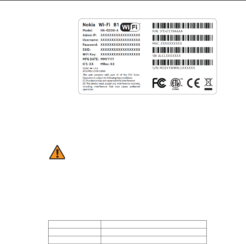
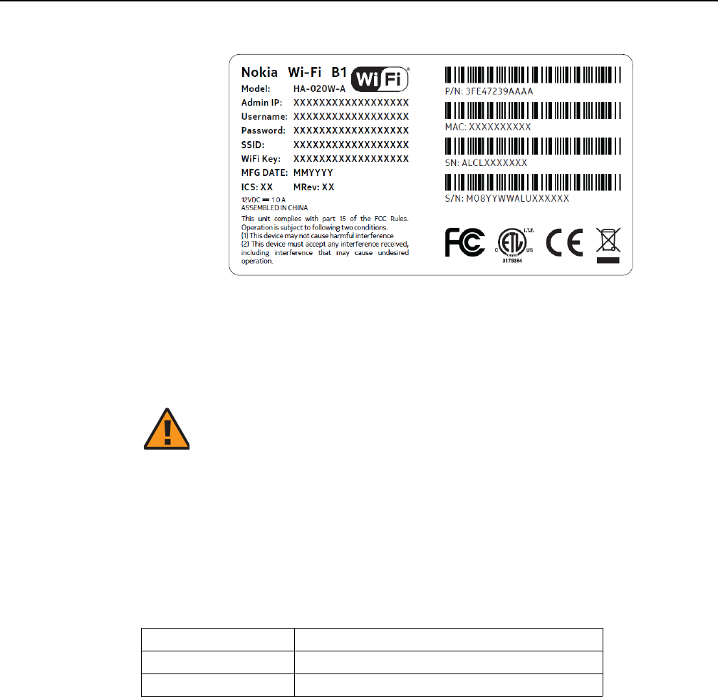
Table 1 provides examples of the text in the various A-020W-A CPE safety labels.
Table 1 Safety labels
Figure 1 shows a sample safety label for the A-020W-A CPE, located on the base of
the unit.
Caution 1 — Possibility of service interruption.
Caution 2 — Service interruption.
Note — Information of special interest.
Label text Description
ETL compliance Communication service equipment US listed.
ESD warning Caution: This assembly contains electrostatic sensitive device.
FCC standards compliance Tested to comply with FCC standards for home or office use.
Release 05.08.01 | June 2018 | Edition 01
7368 ISAM CPE A-020W-A Product Guide ANSI safety guidelines
Issue: 01 3FE-47511-AAAA-TCZZA 11
Figure 1 A-020W-A sample safety label
2.2 Safety standards compliance
This section describes the A-020W-A CPE compliance with North American safety
standards. The A-020W-A is compliant with CE, FCC, CB and ETL requirements.
2.2.1 Responsible party
Table 2 lists the party in the US responsible for this device.
Table 2 Responsible party contact information
Warning — Changes or modifications to this unit not expressly
approved by the party responsible for compliance could void
the user's authority to operate the equipment.
Legal Company name Nokia USA Inc.
Address 2301 SUGAR BUSH RD. STE 300, RALEIGH, NC 27612
Phone, Fax +1 866 582-3688
Release 05.08.01 | June 2018 | Edition 01

ANSI safety guidelines
12
7368 ISAM CPE A-020W-A Product Guide
3FE-47511-AAAA-TCZZA Issue: 01
2.2.2 Energy-related products standby and off modes
compliance
Hereby, Nokia declares that the A-020W-A CPE devices are in compliance with the
essential requirements and other relevant provisions of Directive 2009/125/EC
together with Commission Regulation (EC) No 1275/2008 and Commission
Regulation (EC) No 801/2013.
The A-020W-A CPE devices qualify as high network availability (HiNA) equipment.
Since the main purpose of A-020W-A devices is to provide network functionality with
HiNA 7 days /24 hours, the modes Off/Standby, Power Management, and Networked
Standby are inappropriate.
For information about the type and number of network ports, see “A-020W-A
interfaces and interface capacity” in chapter 5.
For information about power consumption, see “A-020W-A detailed specifications” in
chapter 5.
2.2.3 FCC statement
This equipment has been tested and found to comply with the limits for a Class B
digital device, pursuant to part 15 of the FCC Rules. These limits are designed to
provide reasonable protection against harmful interference in a residential
installation. This equipment generates, uses and can radiate radio frequency energy
and, if not installed and used in accordance with the instructions, may cause harmful
interference to radio communications. However, there is no guarantee that
interference will not occur in a particular installation. If this equipment does cause
harmful interference to radio or television reception, which can be determined by
turning the equipment off and on, the user is encouraged to try to correct the
interference by one or more of the following measures:
•Reorient or relocate the receiving antenna.
•Increase the separation between the equipment and receiver.
•Connect the equipment into an outlet on a circuit different from that to which the
receiver is connected.
•Consult the dealer or an experienced radio/TV technician for help.
Release 05.08.01 | June 2018 | Edition 01
7368 ISAM CPE A-020W-A Product Guide ANSI safety guidelines
Issue: 01 3FE-47511-AAAA-TCZZA 13
2.2.4 FCC Radiation Exposure Statement
This device complies with FCC radiation exposure limits set forth for an uncontrolled
environment and it also complies with Part 15 of the FCC RF Rules. This equipment
must be installed and operated in accordance with provided instructions and the
antenna(s) used for this transmitter must be installed to provide a separation
distance of at least 20 cm from all persons and must not be co-located or operating
in conjunction with any other antenna or transmitter. End-users and installers must
be provided with antenna installation instructions and consider removing the
no-collocation statement.
This device complies with Part 15 of the FCC Rules. Operation is subject to the
following two conditions:
1 this device may not cause harmful interference, and
2 this device must accept any interference received, including interference that
may cause undesired operation.
2.2.5 Resistibility requirements compliance
The A-020W-A CPE equipment complies with the requirements of ITU
Recommendation K.21 for resistibility of telecommunication equipment installed in
customer premises to overvoltage and overcurrents.
2.3 Electrical safety guidelines
This section provides the electrical safety guidelines for the A-020W-A CPE
equipment.
Caution — Any changes or modifications not expressly
approved by the party responsible for compliance could void
the user's authority to operate the equipment.
Note — The devices comply with the U.S. National Electrical
Code. However, local electrical authorities have jurisdiction
when there are differences between the local and U.S.
standards.
Release 05.08.01 | June 2018 | Edition 01

ANSI safety guidelines
14
7368 ISAM CPE A-020W-A Product Guide
3FE-47511-AAAA-TCZZA Issue: 01
2.3.1 Power supplies
The use of any non-Nokia approved power supplies or power adapters is not
supported or endorsed by Nokia. Such use will void any warranty or support contract
with Nokia. Such use greatly increases the danger of damage to equipment or
property.
2.3.2 Cabling
The following are the guidelines regarding cables used for the A-020W-A CPE
equipment:
•Use only cables approved by the relevant national electrical code.
Release 05.08.01 | June 2018 | Edition 01
7368 ISAM CPE A-020W-A Product Guide ETSI safety guidelines
Issue: 01 3FE-47511-AAAA-TCZZA 15
3 ETSI safety guidelines
This chapter provides information about the mandatory regulations that govern the
installation and operation of A-020W-A CPE equipment.
3.1 Safety instructions
This section describes the safety instructions that are provided in the customer
documentation and on the equipment.
3.1.1 Safety instruction boxes
The safety instruction boxes are provided in the customer documentation. Observe
the instructions to meet safety requirements.
The following is an example of the Danger box.
The Danger box indicates that the described activity or situation may pose a threat
to personal safety. It calls attention to a situation or procedure which, if not correctly
performed or adhered to, may result in death or serious physical harm.
Do not proceed beyond a Danger box until the indicated conditions are fully
understood and met.
The following is an example of the Warning box.
The Warning box indicates that the described activity or situation may, or will, cause
equipment damage, loss of data, or serious performance problems. It identifies a
possible equipment-damaging situation or provides essential information to avoid the
degradation of system operations or data.
Do not proceed beyond a warning until the indicated conditions are fully understood
and met.
Danger — Possibility of personal injury.
Warning 1 — Possibility of equipment damage.
Warning 2 — Possibility of data loss.
Release 05.08.01 | June 2018 | Edition 01
ETSI safety guidelines
16
7368 ISAM CPE A-020W-A Product Guide
3FE-47511-AAAA-TCZZA Issue: 01
The following is an example of the Caution box.
The Caution box indicates that the described activity or situation may, or will, cause
service interruption.
Do not proceed beyond a caution until the indicated conditions are fully understood
and met.
The following is an example of the Note box.
The Note box provides information that assists the personnel working with A-020W-A
CPE equipment. It does not provide safety-related instructions.
3.1.2 Safety-related labels
The A-020W-A CPE equipment is labeled with the specific safety instructions and
compliance information that is related to a variant of the A-020W-A. Observe the
instructions on the safety labels.
Table 3 provides sample safety labels on the A-020W-A CPE equipment.
Table 3 Safety labels
Figure 2 shows a sample safety label for the A-020W-A CPE, located on the base of
the unit.
Caution 1 — Possibility of service interruption.
Caution 2 — Service interruption.
Note — Information of special interest.
Label Text Description
ESD warning Caution: This assembly contains an electrostatic sensitive device.
CE marking Indicates compliance to the European Council Directives, including the
EN60950-1 safety
Release 05.08.01 | June 2018 | Edition 01
7368 ISAM CPE A-020W-A Product Guide ETSI safety guidelines
Issue: 01 3FE-47511-AAAA-TCZZA 17
Figure 2 A-020W-A sample safety label
3.2 Safety standards compliance
This section describes the device compliance with European safety standards.
3.2.1 Responsible party
Table 4 lists the party in the US responsible for this device.
Table 4 Responsible party contact information
Warning — Changes or modifications to this unit not expressly
approved by the party responsible for compliance could void
the user's authority to operate the equipment.
Legal Company name Nokia USA Inc.
Address 2301 SUGAR BUSH RD. STE 300, RALEIGH,NC 27612
Phone, Fax +1 866 582-3688
Release 05.08.01 | June 2018 | Edition 01

ETSI safety guidelines
18
7368 ISAM CPE A-020W-A Product Guide
3FE-47511-AAAA-TCZZA Issue: 01
3.2.2 Energy-related products standby and off modes
compliance
Hereby, Nokia declares that the A-020W-A CPE devices are in compliance with the
essential requirements and other relevant provisions of Directive 2009/125/EC
together with Commission Regulation (EC) No 1275/2008 and Commission
Regulation (EC) No 801/2013.
The A-020W-A CPE devices qualify as high network availability (HiNA) equipment.
Since the main purpose of A-020W-A devices is to provide network functionality with
HiNA 7 days /24 hours, the modes Off/Standby, Power Management, and Networked
Standby are inappropriate.
For information about the type and number of network ports, see “A-020W-A
interfaces and interface capacity” in chapter 5.
For information about power consumption, see “A-020W-A detailed specifications” in
chapter 5.
3.2.3 EMC and RED compliance
The A-020W-A CPE equipment complies with the following EMC, EMI, and ESD
requirements:
•EN 300-386: Electromagnetic Compatibility and Radio Spectrum Matters (ERM):
Telecommunications Network Equipment; Electromagnetic Compatibility (EMC)
requirements; Electrostatic Discharge (ESD) requirements
•European Council Directive 2014/30/EU
•European Council Directive 2014/53/EU
•EN300328: Wide band transmission systems; data transmission equipment
operating in the 2.4 GHz ISM band using wide band modulation techniques
•EN301893: 5 GHz RLAN
•EN50385: Compliance of base station equipment with a radio frequency of
electromagnetic field exposure limits (110MHz-100GHz)
3.2.4 Equipment safety standard compliance
The A-020W-A CPE equipment complies with the requirements of EN 62368-1,
Safety of Information Technology Equipment for use in a restricted location.
Release 05.08.01 | June 2018 | Edition 01

7368 ISAM CPE A-020W-A Product Guide ETSI safety guidelines
Issue: 01 3FE-47511-AAAA-TCZZA 19
3.2.5 Environmental standard compliance
The A-020W-A CPE equipment complies with the following EN 300 019 European
environmental standards:
•ETS 300 019-2-1 Storage Class T1.1
•ETS 300 019-2-2 Transport Class T2.3
•ETS 300 019-2-3 Stationary Class T3.1E
3.2.6 Resistibility requirements compliance
The A-020W-A CPE equipment complies with the requirements of ITU
Recommendation K.21 for resistibility of telecommunication equipment installed in
customer premises to over voltage and overcurrents.
3.3 Electrical safety guidelines
This section provides the electrical safety guidelines for the A-020W-A CPE
equipment.
3.3.1 Power supplies
The use of any non-Nokia approved power supplies or power adapters is not
supported or endorsed by Nokia. Such use will void any warranty or support contract
with Nokia. Such use greatly increases the danger of damage to equipment or
property.
3.3.2 Cabling
The following are the guidelines regarding cables used for the A-020W-A CPE
equipment:
•All cables must be approved by the relevant national electrical code.
Note — The devices comply with BS EN 61140.
Release 05.08.01 | June 2018 | Edition 01

ETSI safety guidelines
20
7368 ISAM CPE A-020W-A Product Guide
3FE-47511-AAAA-TCZZA Issue: 01
Release 05.08.01 | June 2018 | Edition 01

7368 ISAM CPE A-020W-A Product Guide ETSI environmental guidelines
Issue: 01 3FE-47511-AAAA-TCZZA 21
4 ETSI environmental guidelines
This chapter provides information about the ETSI environmental regulations that
govern the installation and operation of A-020W-A CPE equipment. This chapter also
includes environmental operation parameters of general interest.
This section describes the environmental instructions that are provided with the
customer documentation, equipment, and location where the equipment resides.
4.1 Environmental requirements
See the technical specification documentation for more information about
temperature ranges.
4.1.1 Transportation
According to EN 300-019-1-2 - Class 2.3, transportation of the equipment must be in
packed, public transportation with no rain on packing allowed.
4.1.2 EU RoHS
European Union (EU) Directive 2011/65/EU, “Restriction of the use of certain
Hazardous Substances” (RoHS), restricts the use of lead, mercury, cadmium,
hexavalent chromium, and certain flame retardants in electrical and electronic
equipment. Nokia products shipped to the EU comply with the EU RoHS Directive.
Nokia has implemented a material/substance content management process. The
process is described in: Nokia process for ensuring RoHS Compliance
(1AA002660031ASZZA). This ensures compliance with the European Union
Directive 2011/65/EU on the Restriction of the Use of Certain Hazardous Substances
in Electrical and Electronic Equipment.
Release 05.08.01 | June 2018 | Edition 01
ETSI environmental guidelines
22
7368 ISAM CPE A-020W-A Product Guide
3FE-47511-AAAA-TCZZA Issue: 01
4.1.3 End-of-life collection and treatment
Electronic products bearing or referencing the symbol shown in Figure 3, when put
on the market within the European Union (EU), shall be collected and treated at the
end of their useful life, in compliance with applicable EU and local legislation. They
shall not be disposed of as part of unsorted municipal waste. Due to materials that
may be contained in the product, such as heavy metals or batteries, the environment
and human health may be negatively impacted as a result of inappropriate disposal.
Figure 3 Recycling/take back/disposal of product symbol
About mark is used in compliance to European Union WEEE Directive (2012/19/EU).
There can be different requirements for collection and treatment in different member
states of the European Union.
In compliance with legal requirements and contractual agreements, where
applicable, Nokia will offer to provide for the collection and treatment of Nokia
products bearing the logo shown in Figure 3 at the end of their useful life, or products
displaced by Nokia equipment offers. For information regarding take-back of
equipment by Nokia, or for more information regarding the requirements for
recycling/disposal of product, contact your Nokia account manager or Nokia take
back support at sustainability.global@nokia.com.
Note — In the European Union, a solid bar under the symbol for
a crossed-out wheeled bin indicates that the product was put on
the market after 13 August 2005.
Release 05.08.01 | June 2018 | Edition 01

7368 ISAM CPE A-020W-A Product Guide A-020W-A unit data sheet
Issue: 01 3FE-47511-AAAA-TCZZA 23
5 A-020W-A unit data sheet
5.1 A-020W-A part numbers and identification
5.2 A-020W-A general description
5.3 A-020W-A software and installation feature support
5.4 A-020W-A interfaces and interface capacity
5.5 A-020W-A LEDs
5.6 A-020W-A detailed specifications
5.7 A-020W-A functional blocks
5.8 A-020W-A standards compliance
5.9 A-020W-A special considerations
5.1 A-020W-A part numbers and identification
Table 5 provides part numbers and identification information for the A-020W-A CPE.
Table 5 Identification of A-020W-A
Ordering part
number
Provisioning
number
Description CLEC CPR ECI/
Bar
code
3FE 47471 AA 3FE 47511 AA CPE with WiFi Wi-Fi Access Point and range extender, 2
Gigabit Ethernet UNI, dual bands 802.11ac 2x2 and
802.11n 2x2 WiFi; 12V/1A AC/DC US plug external power
supply variant. The following accessories are included:
•CA_RJ45: 1 1.5m Yellow
•Power adapter: 1 1.5m Black
•Packing list: 1 A6 Normal
———
3FE 47471 BA 3FE 47511 BA CPE with Wi-Fi Access Point and range extender, 2
Gigabit Ethernet UNI, dual bands 802.11ac 2x2 and
802.11n 2x2 WiFi; 12V/1A AC/DC EU plug, 2-pin external
power supply variant. The following accessories are
included:
•CA_RJ45: 1 1.5m Yellow
•Power adapter: 1 1.5m Black
•Packing list: 1 A6 Normal
———
(1 of 2)
Release 05.08.01 | June 2018 | Edition 01

A-020W-A unit data sheet
24
7368 ISAM CPE A-020W-A Product Guide
3FE-47511-AAAA-TCZZA Issue: 01
5.2 A-020W-A general description
WiFi is abundantly deployed in home networks. Users require a seamless
experience at home to connect their devices. Traditional WiFi networks require
unique SSIDs for each of the access points or WiFi extenders, which complicated the
user experience. The Nokia WiFi network simplifies the user experience by providing
a seamless network and automating network optimization.
The Nokia WiFi solution includes a Nokia WiFi gateway, one or more Nokia WiFi
beacons, the WiFi Care Portal for the customer care team of the operator, and a
mobile application for end-user self care.
The A-020W-A CPE is an Ethernet residential gateway and WiFi beacon in the Nokia
WiFi solution. The residential gateway is the central controller of the network while
the beacon can extend the WiFi coverage to every corner of the home, providing
seamless roaming to the connected devices.
The A-020W-A CPE has built-in concurrent dual-band WiFi 802.11b/g/n and
802.11ac networking with triple-play capability. A-020W-A devices can be configured
using the Nokia WiFi Mobile App, which can be downloaded on both iOS and Android
devices.
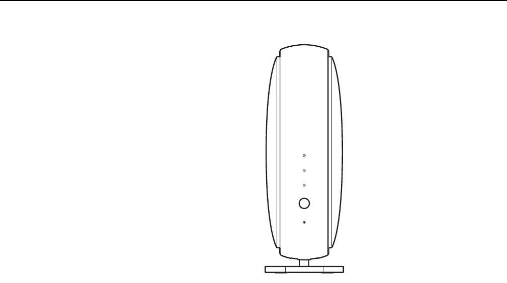
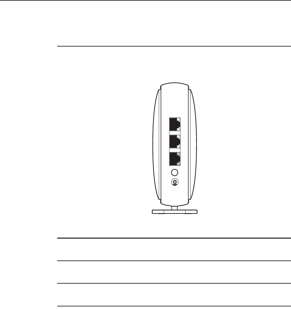
Figure 4 shows the A-020W-A CPE in its stand.
3FE 47471 CA 3FE 47511 BA CPE with Wi-Fi Access Point and range extender, 2
Gigabit Ethernet UNI, dual bands 802.11ac 2x2 and
802.11n 2x2 WiFi; 12V/1A AC/DC UK plug, 3-pin external
power supply variant. The following accessories are
included:
•CA_RJ45: 1 1.5m Yellow
•Power adapter: 1 1.5m Black
•Packing list: 1 A6 Normal
———
3FE 47471 DA 3FE 47511 DA CPE with Wi-Fi Access Point and range extender, 2
Gigabit Ethernet UNI, dual bands 802.11ac 2x2 and
802.11n 2x2 WiFi; 12V/1A AC/DC AU plug external power
supply variant. The following accessories are included:
•CA_RJ45: 1 1.5m Yellow
•Power adapter: 1 1.5m Black
•Packing list: 1 A6 Normal
———
Ordering part
number
Provisioning
number
Description CLEC CPR ECI/
Bar
code
(2 of 2)
Release 05.08.01 | June 2018 | Edition 01
7368 ISAM CPE A-020W-A Product Guide A-020W-A unit data sheet
Issue: 01 3FE-47511-AAAA-TCZZA 25
Figure 4 A-020W-A CPE
A-020W-A CPEs provide the following functions:
•GE Ethernet uplink
•Concurrent 802.11n 2x2 MIMO in 2.4GHz and 802.11ac 2x2 MIMO in 5GHz
•auto-negotiation for speed and duplex on a port by port basis
•MDI/MDIX Ethernet auto-negotiation or manual configuration
•routed mode per LAN port
•Advanced data features: VLAN tag manipulation, classification, and filtering
•Traffic classification and QoS capability
•Internal Switch
•Line Rate L2 traffic
•UPnP IGD2.0 support
•Internal DHCP server, with configurable DHCP pool and gateway
•64/128 WEP encryption
•WPA, WPA-PSK/TKIP
•WPA2, WPA2-PSK/AES
•support for multiple SSIDs (private and public instances); contact your Nokia
representative for further details.
•WPS on/off button
•Ethernet-based Point-to-Point (PPPoE) and IP over Ethernet (IPoE)
•Network Address Translation (NAT)
•Network Address Port Translation (NAPT)
INTERNET
WPS
PA I R
RESET
POWER
28229
Release 05.08.01 | June 2018 | Edition 01

A-020W-A unit data sheet
26
7368 ISAM CPE A-020W-A Product Guide
3FE-47511-AAAA-TCZZA Issue: 01
•TR-069 management
•ALG and UPnP port forwarding
•DMZ
•IP/MAC filter
•Multi-level firewall
•DNS server
•DHCP client/server
•support for HT40 and VHT80 modes for increased channel bandwidth
•support for up to 32 simultaneous wireless connections
•remote software image download
5.2.1 TR-069 object support for WiFi parameters
The A-020W-A CPE supports the status retrieval and configuration of the following
WiFi parameters via TR-069:
•channel
•SSID
•password for WPA and WEP
•Tx power (transmission rate in dBm)
These are the same TR-069 object parameters that are supported in the GUI. For
more information, see Tables 21 and 22 in the chapter “Configure a A-020W-A”.
5.2.2 Independent TR69 session with SaaS
The prime communication between the Nokia cloud management solution and the
A-020W-A CPE is TR-069.
To keep the Nokia Home WiFi management independent from the ACS of the carrier,
The device can establish an independent TR-069 session with the SaaS.
The SaaS WiFi Care URL and credentials can be programmed from the ACS solution
of the carrier, or they can be incorporated in the device pre-configuration.
5.2.3 TR69 authentication using TLS and CA certificates
A-020W-A CPE devices support encrypted remote TR-069 management using TLS,
as well as ACS authentication using SHA-256 pre-installed certificates.
If the ACS URL is set to the https://... format, by default, the connection will use TLS
without authentication mode. The A-020W-A CPE can also authenticate the ACS
using a pre-installed CA certificate.
Release 05.08.01 | June 2018 | Edition 01

7368 ISAM CPE A-020W-A Product Guide A-020W-A unit data sheet
Issue: 01 3FE-47511-AAAA-TCZZA 27
5.3 A-020W-A software and installation feature
support
For information on installing or replacing the A-020W-A CPE, see:
•Install a A-020W-A
•Replace a A-020W-A
5.4 A-020W-A interfaces and interface capacity
Table 6 describes the supported interfaces and interface capacity for A-020W-A CPE
devices.
Table 6 A-020W-A interface connection capacity
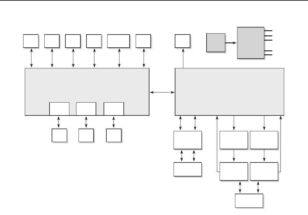
5.4.1 A-020W-A connections and components
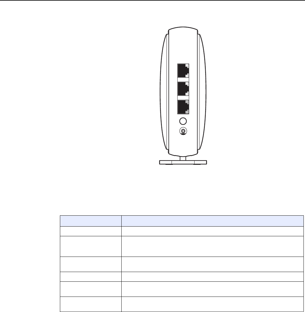
Figure 5 shows the physical connections for A-020W-A CPE devices.
Type and
model
Maximum capacity
POTS 10/ 100
BASE-T
10/ 100/1000
1000 BASE-T
RF video
(CATV)
MoCA VDSL2 E1/T1 Local
craft
GE uplink
A-020W-A — — 2 — — — — — 1
Release 05.08.01 | June 2018 | Edition 01
A-020W-A unit data sheet
28
7368 ISAM CPE A-020W-A Product Guide
3FE-47511-AAAA-TCZZA Issue: 01
Figure 5 A-020W-A physical connections
Table 7 describes the physical connections for A-020W-A CPE devices.
Table 7 A-020W-A physical connections
5.5 A-020W-A LEDs
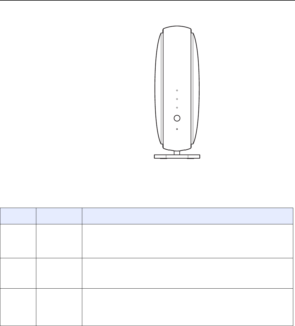
Figure 6 shows the A-020W-A CPE LEDs.
Connection Description
On/Off button This button powers the unit on or off.
LAN 1/LAN 2 This connection is provided through Ethernet RJ-45 connectors. Up to two
10/100/1000 Base-T Ethernet interfaces are supported.The Ethernet ports can
support both data and in-band video services on both interfaces.
WAN port This connection is provided through an RJ-45 Gigabit Ethernet interface. One
10/100/1000 Base-T Ethernet interface is supported.
WPS ON/Off button This button is used to start the WiFi Protected Setup (WPS) of new WiFi devices.
Reset button Pressing the Reset button for less than 10 seconds reboots the device; pressing
the Reset button for 10 seconds resets the device to the factory defaults.
Power input This connection is provided through the power connector. A power cable fitted with
a barrel connector is used to make the connection.
ON/OFF
WAN
LAN 2
LAN 1
28230
Release 05.08.01 | June 2018 | Edition 01
7368 ISAM CPE A-020W-A Product Guide A-020W-A unit data sheet
Issue: 01 3FE-47511-AAAA-TCZZA 29
Figure 6 A-020W-A LEDs
Table 8 provides LED descriptions for the A-020W-A CPE.
Table 8 A-020W-A LEDs
INTERNET
WPS
PA I R
RESET
POWER
28229
Indicator LED color and
behavior
LED behavior description
Power Green
Off
Red (default until
software is
running)
Power on
Power off
Failed on startup (for example corrupt flash), self test failed on startup, or self test failed during
regular operation.
WPS (2.4G
and 5G)
Green solid
Green flashing
Off
Solid Red
WPS is successful (light turns off five minutes after successful WiFi setup)
WPS is in progress (light turns off after two minutes if WPS is unsuccessful)
WPS is not in progress
WPS error or overlapped (lights for 20 s and then turns off)
INTERNET Green solid
Green flashing
Red
RG mode: Internet is up, IP address is assigned
Beacon mode: Connection to the access point is good, IP address is assigned
RG mode: Attempting to connect to the Internet
RG mode: Gateway has no Internet connection
Beacon mode: No or poor connection to the access point
Release 05.08.01 | June 2018 | Edition 01
A-020W-A unit data sheet
30
7368 ISAM CPE A-020W-A Product Guide
3FE-47511-AAAA-TCZZA Issue: 01
5.6 A-020W-A detailed specifications
Table 9 lists the physical specifications for the A-020W-A CPE.
Table 9 A-020W-A physical specifications
Table 10 lists the power consumption specifications for the A-020W-A CPE.
Table 10 A-020W-A power consumption specifications
Table 11 lists the environmental specifications for the A-020W-A CPE.
Table 11 A-020W-A environmental specifications
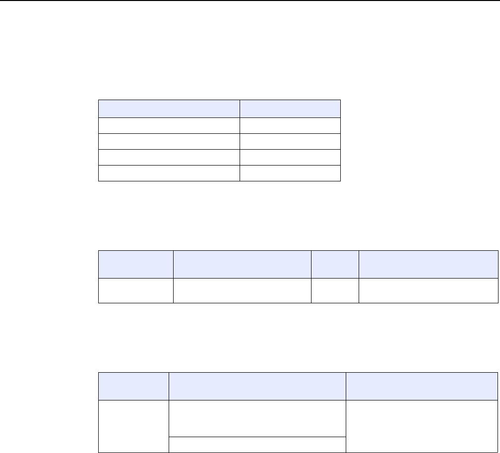
5.7 A-020W-A functional blocks
A-020W-A CPE devices are single-residence units that support Wireless (WiFi)
service. WiFi service on these devices is compliant with the IEEE 802.11 standard.
In addition to the WiFi service, these devices transmit Ethernet packets to two RJ-45
Ethernet ports.
Figure 7 shows the functional blocks for the A-020W-A CPE.
Description Specification
Width 42.2 mm (1.66 in.)
Height 123.22 mm (4.85 in.)
Depth 112.64 mm (4.43 in.)
Weight [within ± 0.5 lb (0.23 kg)] 230g (0.5 lb)
Maximum power
(Not to exceed)
Condition Minimum
power
Condition
8 W 2 10/100/1000 Base-T Ethernet,
WiFi operational
2 W interfaces/services not provisioned
Mounting
method
Temperature range and humidity Altitude
On desk or shelf Operating: -5°C to 45°C (-23°F to 113°F)
ambient temperature
5% to 95% relative humidity, non-condensing
Contact your Nokia technical support
representative for more information
Storage: -20°C to 85°C (-4°F to 185°F)
Release 05.08.01 | June 2018 | Edition 01
7368 ISAM CPE A-020W-A Product Guide A-020W-A unit data sheet
Issue: 01 3FE-47511-AAAA-TCZZA 31
Figure 7 Single-residence WiFi CPE with Gigabit Ethernet
5.8 A-020W-A standards compliance
A-020W-A CPE devices are compliant with the following standards:
•IEEE 802.1D (bridging), 802.1p (QoS), 802.1q (VLAN)
•IEEE 802.3 (2012) (Ethernet standard)
•IEEE 802.11n/ac 2x2 (WiFi 5G) and 802.11b/g/n 2x2 (WiFi 2.4G)
5.9 A-020W-A special considerations
This section describes the special considerations for A-020W-A CPE devices.
Flash Clock UART EEPROMDDR3
GE
PHY
GE
PHY
GE
PHY
RJ-45 RJ-45RJ-45
LEDs LEDs
2.4G WIFI
PA & LNA
Circuit
2.4G
Antenna*2
SoC
DDR3 PBI I2C GPIO GPIO
PCIe 0
Chain
1
Chain
0
5G WIFI
LNA & SW
Circuit
5G
Antenna*2
Chain
2
3.3V
1.5V
1.0V
1.6V
1.1V
Power
Regulators
12V
Power
In
28228
5G WIFI
PA
Circuit
Chain
3
5G WIFI
PA
Circuit
5G WIFI
LNA & SW
Circuit
WiFi SoC
Release 05.08.01 | June 2018 | Edition 01

A-020W-A unit data sheet
32
7368 ISAM CPE A-020W-A Product Guide
3FE-47511-AAAA-TCZZA Issue: 01
5.9.1 WiFi service
A-020W-A CPE devices feature WiFi service as well as data services. WiFi is a
wireless networking technology that uses radio waves to provide wireless HSI and
network connections. This device complies with the IEEE 802.11 standards, which
the WiFi Alliance defines as the basis for WiFi technology.
5.9.1.1 WiFi standards and certifications
The WiFi service on A-020W-A CPE devices support the following IEEE standards
and WiFi Alliance certifications:
•compliant with IEEE 802.11 standards
•certified for IEEE 802.11b/g/n/ac standards
•WPA support including WPA-PSK
•certified for WPA2-Personal and WPA2-Enterprise
5.9.1.2 WiFi GUI features
A-020W-A CPE devices have HTML-based WiFi configuration GUIs.
In addition to the traditional web-based GUI, the home user can download and use
a mobile app for managing the A-020W-A CPE.
5.9.2 A-020W-A considerations and limitations
None.
Release 05.08.01 | June 2018 | Edition 01

7368 ISAM CPE A-020W-A Product Guide Install a A-020W-A
Issue: 01 3FE-47511-AAAA-TCZZA 33
6 Install a A-020W-A
6.1 Purpose
6.2 General
6.3 Prerequisites
6.4 Recommended tools
6.5 Safety information
6.6 Procedure
6.1 Purpose
This chapter provides the steps to install a A-020W-A CPE.
6.2 General
The steps listed in this chapter describe mounting and cabling for a A-020W-A CPE.
6.3 Prerequisites
You need the following items before beginning the installation:
•all required cables
6.4 Recommended tools
You need the following tools for the installation:
•RJ-45 Ethernet cable
•paper clip
Release 05.08.01 | June 2018 | Edition 01

Install a A-020W-A
34
7368 ISAM CPE A-020W-A Product Guide
3FE-47511-AAAA-TCZZA Issue: 01
6.5 Safety information
Read the following safety information before installing the unit.
Danger 1 — Hazardous electrical voltages and currents can
cause serious physical harm or death. Always use insulated
tools and follow proper safety precautions when connecting or
disconnecting power circuits.
Danger 2 — Make sure all sources of power are turned off and
have no live voltages present on feed lines or terminals. Use a
voltmeter to measure for voltage before proceeding.
Danger 3 — Always contact the local utility company before
connecting the enclosure to the utilities.
Caution — Keep indoor devices out of direct sunlight.
Prolonged exposure to direct sunlight can damage the unit.
Note 1 — Observe the local and national laws and regulations
that may be applicable to this installation.
Note 2 — Observe the following:
•The device should be installed in accordance with the
applicable requirements of the NEC or CEC. Local
authorities and practices take precedent when there is
conflict between the local standard and the NEC or CEC.
•The device must be installed by qualified service personnel.
•Indoor units must be installed with cables that are suitably
rated and listed for indoor use.
•See the detailed specifications in the A-020W-A unit data
sheet for the temperature ranges for these devices.
Release 05.08.01 | June 2018 | Edition 01
7368 ISAM CPE A-020W-A Product Guide Install a A-020W-A
Issue: 01 3FE-47511-AAAA-TCZZA 35
6.6 Procedure
Use this procedure to install a A-020W-A CPE.
1Place the unit on a flat surface, such as a desk or shelf.
2Review the connection locations as shown in Figures 8.
Figure 8 A-020W-A connections
3Connect the Ethernet cables to the RJ-45 ports; see Figure 8 for the location of the RJ-45
ports.
4Connect the WAN cable to the RJ-45 WAN port; see Figure 8 for the location of the RJ-45
WAN port.
Note — The A-020W-A CPE cannot be stacked with another A-020W-A
or with other equipment. The installation requirements are:
•allow a minimum 100 mm clearance above the top cover
•allow a minimum 50 mm clearance from the side vents
•do not place any heat source directly above the top cover or below the
bottom cover
ON/OFF
WAN
LAN 2
LAN 1
28230
Release 05.08.01 | June 2018 | Edition 01
Install a A-020W-A
36
7368 ISAM CPE A-020W-A Product Guide
3FE-47511-AAAA-TCZZA Issue: 01
5Connect the power cable to the power connector.
6Power up the unit by using the On/Off power switch.
7Verify the LEDs and voltage status.
8Activate and test the services.
9If necessary, reset the A-020W-A CPE.
iLocate the Reset button as shown in Figure 8.
ii Insert the end of a straightened paper clip or other narrow object into the hole in the
Reset button to reset the device.
10 STOP. This procedure is complete.
Note — Observe the following:
•Units must be powered by a Listed or CE approved and marked
limited power source power supply with a minimum output rate of
12 V dc, 1 A. The polarity of the power adapter plug must match the
A-020W-A CPE.
Note — Resetting the device will return all settings to factory default
values; any configuration customization will be lost.
Release 05.08.01 | June 2018 | Edition 01

7368 ISAM CPE A-020W-A Product Guide Replace a A-020W-A
Issue: 01 3FE-47511-AAAA-TCZZA 37
7 Replace a A-020W-A
7.1 Purpose
7.2 General
7.3 Prerequisites
7.4 Recommended tools
7.5 Safety information
7.6 Procedure
7.1 Purpose
This chapter provides the steps to replace a A-020W-A CPE.
7.2 General
The steps listed in this chapter describe mounting and cabling for a A-020W-A CPE.
7.3 Prerequisites
You need the following items before beginning the installation:
•all required cables
7.4 Recommended tools
You need the following tools for replacing the A-020W-A CPE:
•RJ-45 Ethernet cable
•paper clip
Release 05.08.01 | June 2018 | Edition 01

Replace a A-020W-A
38
7368 ISAM CPE A-020W-A Product Guide
3FE-47511-AAAA-TCZZA Issue: 01
7.5 Safety information
Read the following safety information before replacing the unit.
Danger 1 — Hazardous electrical voltages and currents can
cause serious physical harm or death. Always use insulated
tools and follow proper safety precautions when connecting or
disconnecting power circuits.
Danger 2 — Make sure all sources of power are turned off and
have no live voltages present on feed lines or terminals. Use a
voltmeter to measure for voltage before proceeding.
Danger 3 — Always contact the local utility company before
connecting the enclosure to the utilities.
Caution — Keep indoor devices out of direct sunlight.
Prolonged exposure to direct sunlight can damage the unit.
Note 1 — Observe the local and national laws and regulations
that may be applicable to this installation.
Note 2 — Observe the following:
•The device should be installed in accordance with the
applicable requirements of the NEC or CEC. Local
authorities and practices take precedent when there is
conflict between the local standard and the NEC or CEC.
•The device must be installed by qualified service personnel.
•Indoor units must be installed with cables that are suitably
rated and listed for indoor use.
•See the detailed specifications in the A-020W-A unit data
sheet for the temperature ranges for these devices.
Release 05.08.01 | June 2018 | Edition 01
7368 ISAM CPE A-020W-A Product Guide Replace a A-020W-A
Issue: 01 3FE-47511-AAAA-TCZZA 39
7.6 Procedure
Use this procedure to replace a A-020W-A CPE.
1Power down the unit by using the on/off power switch. See Figure 9 for the connections on
the A-020W-A CPE.
Figure 9 A-020W-A connections
2Disconnect the WAN, Ethernet, and power cables from the A-020W-A CPE; see Figure 9 for
the connector locations on the A-020W-A.
3Replace the A-020W-A CPE with the new A-020W-A. The device can be placed on any flat
surface, such as a desk or shelf.
4Connect the Ethernet cables directly to the RJ-45 ports; see Figure 9 for the location of the
RJ-45 ports.
5Connect the WAN cable directly to the RJ-45 port; see Figure 9 for the location of the RJ-45
WAN port.
ON/OFF
WAN
LAN 2
LAN 1
28230
Release 05.08.01 | June 2018 | Edition 01
Replace a A-020W-A
40
7368 ISAM CPE A-020W-A Product Guide
3FE-47511-AAAA-TCZZA Issue: 01
6Connect the power cable to the power connector.
7Power up the unit by using the On/Off power button.
8Verify the LEDs and voltage status.
9Activate and test the services.
10 If necessary, reset the A-020W-A CPE.
iLocate the Reset button on a A-020W-A CPE, as shown in Figure 9.
ii Insert the end of a straightened paper clip or other narrow object into the hole in the
Reset button to reset the device.
11 STOP. This procedure is complete.
Note — Observe the following:
•Units must be powered by a Listed or CE approved and marked
limited power source with a minimum output rate of 12 V dc, 1 A. The
polarity of the power adapter plug must match the A-020W-A CPE.
Note — Resetting the device will return all settings to factory default
values; any configuration customization will be lost.
Release 05.08.01 | June 2018 | Edition 01

7368 ISAM CPE A-020W-A Product Guide Configure a A-020W-A
Issue: 01 3FE-47511-AAAA-TCZZA 41
8 Configure a A-020W-A
8.1 GUI configuration
8.1 GUI configuration
Use the procedures below to use the web-based GUI for the A-020W-A CPE.
The A-020W-A CPE is used as an Ethernet gateway to connect devices in the home
to the Internet. The GUI provides a variety of features for the home network including
routing and firewall capability. By using the GUI, users can configure the right
network connectivity fort all equipment in their home, including personal computers,
set-top boxes, mobile phones, and other consumer electronics devices, to the
Internet.
8.1.1 Login
Use the procedure below to login to the web-based GUI for the A-020W-A CPE.
Procedure 6 Login to web-based GUI
1Open a web browser and enter the IP address of the A-020W-A CPE in the address bar.
The login window appears.
The default gateway IP address is http://192.168.18.1. You can connect to this IP address
using your web browser after connecting your PC to one of Ethernet ports of the A-020W-A
CPE. The static IP address of your PC must be in the same 192.168.18.x subnet as the
A-020W-A.
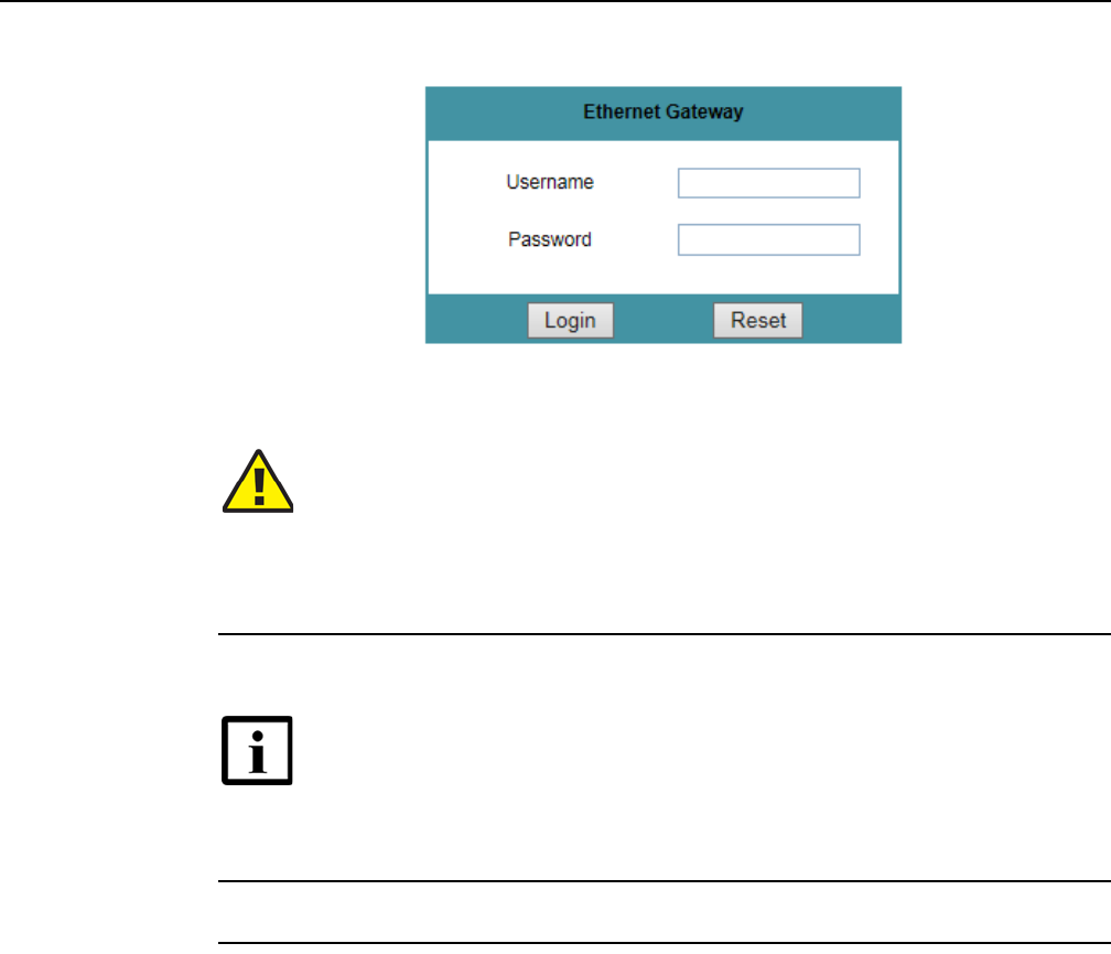
2Enter your username and password in the Log in window, as shown in Figure 10.
The default user name is admin. The default password is a random number, which is included
in the A-020W-A CPE kit.
Release 05.08.01 | June 2018 | Edition 01
Configure a A-020W-A
42
7368 ISAM CPE A-020W-A Product Guide
3FE-47511-AAAA-TCZZA Issue: 01
Figure 10 Web login window
3Click Login. The Device Information screen appears.
4STOP. This procedure is complete.
8.1.2 Device and connection status
The A-020W-A CPE supports the retrieval of a variety of device and connection
information, including:
•device information
•LAN status
•WAN status
•WAN status IPv6
Caution — If you forget the current username and password, press the
reset button for 10s and the default values for the username and
password will be recovered at startup.
Pressing the Reset button for less than 10 seconds reboots the
A-020W-A CPE; pressing the Reset button for 10 seconds resets the
A-020W-A to the factory defaults.
Note — To help protect the security of your Internet connection, the
application displays a pop-up reminder to change both the WiFi password
and the A-020W-A CPE password.
To increase password security, use a minimum of 10 characters,
consisting of a mix of numbers and upper and lowercase letters.
Release 05.08.01 | June 2018 | Edition 01
7368 ISAM CPE A-020W-A Product Guide Configure a A-020W-A
Issue: 01 3FE-47511-AAAA-TCZZA 43
•home networking information
•statistics
Procedure 7 Device information retrieval
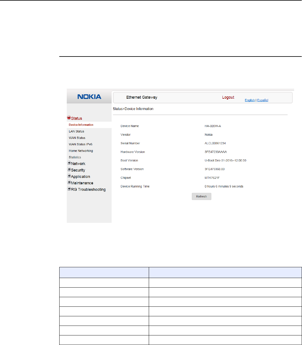
1Select Status > Device Information from the top-level menu in the Ethernet Gateway window,
as shown in Figure 11.
Figure 11 Device Information window
Table 12 describes the fields in the Device Information window.
Table 12 Device Information parameters
Field Description
Device Name Mnemonic of the A-020W-A CPE
Vendor Name of the vendor
Serial Number Serial number of the A-020W-A CPE
Hardware version Hardware version of the A-020W-A CPE
Boot version Boot version of the A-020W-A CPE
Software version Software version of the A-020W-A CPE
Chipset Chipset of the A-020W-A CPE
(1 of 2)
Release 05.08.01 | June 2018 | Edition 01
Configure a A-020W-A
44
7368 ISAM CPE A-020W-A Product Guide
3FE-47511-AAAA-TCZZA Issue: 01
2Click Refresh to update the displayed information.
3STOP. This procedure is complete.
Device Running Time Amount of time the device has run since last reset in hours, minutes,
and seconds
Field Description
(2 of 2)
Release 05.08.01 | June 2018 | Edition 01
7368 ISAM CPE A-020W-A Product Guide Configure a A-020W-A
Issue: 01 3FE-47511-AAAA-TCZZA 45
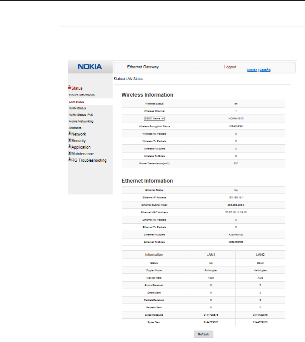
Procedure 8 LAN status retrieval
1Select Status > LAN Status from the top-level menu in the Ethernet Gateway window, as
shown in Figure 12.
Figure 12 LAN status window
Table 13 describes the fields in the LAN status window.
Release 05.08.01 | June 2018 | Edition 01
Configure a A-020W-A
46
7368 ISAM CPE A-020W-A Product Guide
3FE-47511-AAAA-TCZZA Issue: 01
Table 13 LAN status parameters
2Click Refresh to update the displayed information.
3STOP. This procedure is complete.
Field Description
Wireless Information
Wireless Status Indicates whether the wireless is on or off
Wireless Channel Wireless channel number
SSID Name Name of each SSID
Wireless Encryption Status Encryption type used on the wireless connection
Wireless Rx Packets Number of packets received on the wireless connection
Wireless Tx Packets Number of packets transmitted on the wireless connection
Wireless Rx Bytes Number of bytes received on the wireless connection
Wireless Tx Bytes Number of bytes transmitted on the wireless connection
Power Transmission (mW) Power of the wireless transmission, in mW
Ethernet Information
Ethernet Status Indicates whether the Ethernet connection is on or off
Ethernet IP Address IP address of the Ethernet connection
Ethernet Subnet Mask Subnet Mask of the Ethernet connection
Ethernet MAC Address MAC address of the Ethernet connection
Ethernet Rx Packets Number of packets received on the Ethernet connection
Ethernet Tx Packets Number of packets transmitted on the Ethernet connection
Ethernet Rx Bytes Number of bytes received on the Ethernet connection
Ethernet Tx Bytes Number of bytes transmitted on the Ethernet connection
Release 05.08.01 | June 2018 | Edition 01
7368 ISAM CPE A-020W-A Product Guide Configure a A-020W-A
Issue: 01 3FE-47511-AAAA-TCZZA 47
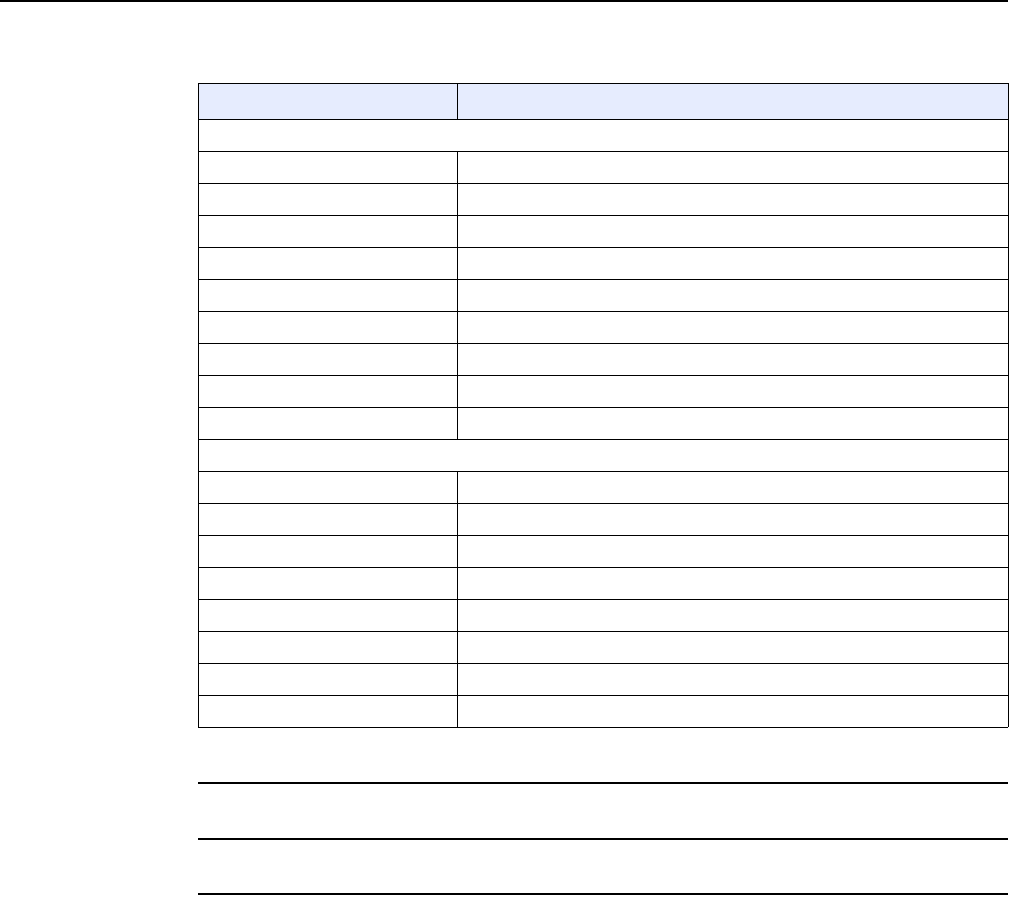
Procedure 9 WAN status retrieval
1Select Status > WAN Status from the top-level menu in the Ethernet Gateway window, as
shown in Figure 13.
Figure 13 WAN Status window
Table 14 describes the fields in the WAN Status window.
Table 14 WAN Status parameters
Field Description
WAN connection list Drop-down menu listing all WAN connections. The connection shown is the
connection for which WAN status will be shown.
Connection Mode Connection mode of the WAN connection
Enable/Disable Select this checkbox to enable the WAN connection
VLAN VLAN ID
(1 of 2)
Release 05.08.01 | June 2018 | Edition 01
Configure a A-020W-A
48
7368 ISAM CPE A-020W-A Product Guide
3FE-47511-AAAA-TCZZA Issue: 01
2Click Refresh to update the displayed information.
3STOP. This procedure is complete.
WAN Link Status Whether the WAN link is up or down
IPv4 Address IPv4 address
Netmask Netmask
Gateway IPv4 gateway address
Primary DNS Primary Domain Name Server
Second DNS Secondary Domain Name Server
Ethernet Link Status Whether the PON link is up or down
Tx Packets Number of packets transmitted on the WAN connection
Rx Packets Number of packets received on the WAN connection
Tx Dropped Number of packets dropped on the transmit WAN connection
Rx Dropped Number of packets dropped on the receive WAN connection
Err Packets Number of errored packets on the WAN connection
Field Description
(2 of 2)
Release 05.08.01 | June 2018 | Edition 01
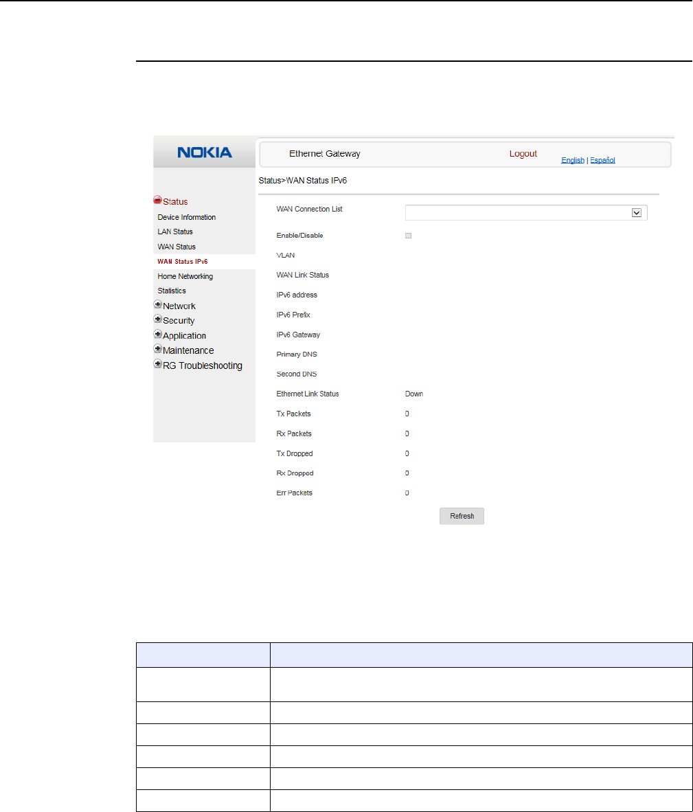
7368 ISAM CPE A-020W-A Product Guide Configure a A-020W-A
Issue: 01 3FE-47511-AAAA-TCZZA 49
Procedure 10 WAN status IPv6 retrieval
1Select Status > WAN Status IPv6 from the top-level menu in the Ethernet Gateway window,
as shown in Figure 14.
Figure 14 WAN Status IPv6 window
Table 15 describes the fields in the WAN status IPv6 window.
Table 15 WAN status IPv6 parameters
Field Description
WAN connection list Drop-down menu listing all WAN connections. The connection selected is the
connection for which WAN status will be shown.
Enable/Disable Select this check box to enable the WAN connection
VLAN VLAN ID
WAN Link Status Whether the WAN link is up or down
IPv6 Address IPv6 address that identifies the device and its location
IPv6 Prefix IPv6 prefix
(1 of 2)
Release 05.08.01 | June 2018 | Edition 01
Configure a A-020W-A
50
7368 ISAM CPE A-020W-A Product Guide
3FE-47511-AAAA-TCZZA Issue: 01
2Click Refresh to update the displayed information.
3STOP. This procedure is complete.
IPv6 Gateway IPv6 gateway address
Primary DNS Primary Domain Name Server address
Second DNS Secondary Domain Name Server address
Ethernet Link Status Whether the link is up or down
Tx Packets Number of packets transmitted on the WAN connection
Rx Packets Number of packets received on the WAN connection
Tx Dropped Number of packets dropped on the transmit WAN connection
Rx Dropped Number of packets dropped on the receive WAN connection
Err Packets Number of errored packets on the WAN connection
Field Description
(2 of 2)
Release 05.08.01 | June 2018 | Edition 01
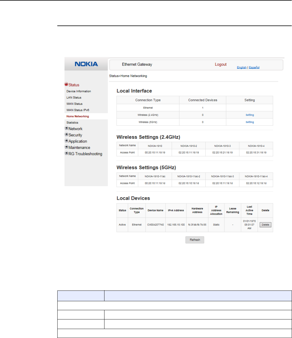
7368 ISAM CPE A-020W-A Product Guide Configure a A-020W-A
Issue: 01 3FE-47511-AAAA-TCZZA 51
Procedure 11 Home networking information retrieval
1Select Status > Home Networking from the top-level menu in the Ethernet Gateway window,
as shown in Figure 15.
Figure 15 Home Networking information window
Table 16 describes the fields in the Home Networking window.
Table 16 Home Networking parameters
Field Description
Local Interface
Ethernet Table displays the number of Ethernet connections and their settings
Wireless Table displays the number of wireless connections and their settings
Wireless Settings
(1 of 2)
Release 05.08.01 | June 2018 | Edition 01
Configure a A-020W-A
52
7368 ISAM CPE A-020W-A Product Guide
3FE-47511-AAAA-TCZZA Issue: 01
2Click Delete to delete a particular local device connection.
3Click Refresh to update the displayed information.
4STOP. This procedure is complete.
Procedure 12 Statistics retrieval
1Select Status > Statistics from the top-level menu in the Ethernet Gateway window.
Statistics are available for LAN ports, WAN ports, and WLAN.
Figure 16 shows the statistics for the LAN ports.
Network Name Name of the wireless network access point
Access Point Hexadecimal address of the wireless access point
Local Devices
Table entry Each entry indicates the status (active or inactive), connection type, device name, IP
address, hardware address, and IP address allocation of each connected local device.
Field Description
(2 of 2)
Release 05.08.01 | June 2018 | Edition 01
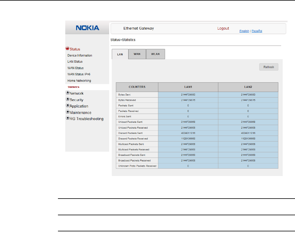
7368 ISAM CPE A-020W-A Product Guide Configure a A-020W-A
Issue: 01 3FE-47511-AAAA-TCZZA 53
Figure 16 Statistics window (LAN port statistics shown)
2Click Refresh to update the displayed information.
3STOP. This procedure is complete.
8.1.3 Network configuration
The A-020W-A CPE also supports network configuration, including:
•LAN
•LAN IPv6
•WAN
•WAN DHCP
•Wireless 2.4G
•Wireless 5G
•wireless schedule
•DNS
Release 05.08.01 | June 2018 | Edition 01
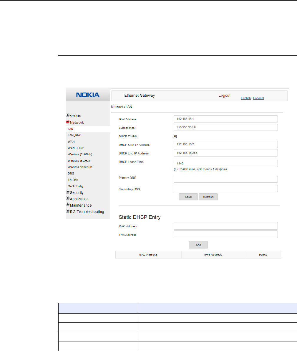
Configure a A-020W-A
54
7368 ISAM CPE A-020W-A Product Guide
3FE-47511-AAAA-TCZZA Issue: 01
•TR-069
•QoS Configuration
Procedure 13 LAN configuration
1Select Network > LAN from the top-level menu in the Ethernet Gateway window, as shown
in Figure 17.
Figure 17 LAN settings window
Table 17 describes the fields in the LAN window.
Table 17 LAN parameters
Field Description
IPv4 Address IP Address of the A-020W-A CPE
Subnet Mask Subnet mask of the A-020W-A CPE
DHCP enable Select this check box to enable DHCP
DHCP Start IP Address Starting DHCP IP address
(1 of 2)
Release 05.08.01 | June 2018 | Edition 01
7368 ISAM CPE A-020W-A Product Guide Configure a A-020W-A
Issue: 01 3FE-47511-AAAA-TCZZA 55
2Configure the LAN.
3Click Save.
4Bind a MAC address to the LAN by entering the MAC and IP addresses in the Static DHCP
Entry fields and then clicking Add. Repeat for all MAC addresses to be bound.
5STOP. This procedure is complete.
DHCP End IP Address Ending DHCP IP address
DHCP Lease Time DHCP lease time (in min)
Primary DNS Primary domain name server address
Secondary DNS Secondary domain name server address
Static DHCP MAC Address Hexadecimal MAC address to associate to the LAN
Static DHCP IP Address IP address to associate to the bound MAC address
Field Description
(2 of 2)
Release 05.08.01 | June 2018 | Edition 01
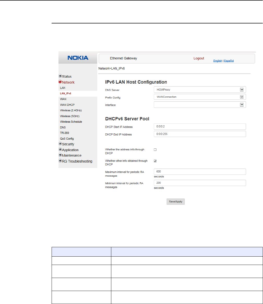
Configure a A-020W-A
56
7368 ISAM CPE A-020W-A Product Guide
3FE-47511-AAAA-TCZZA Issue: 01
Procedure 14 LAN IPv6 networking configuration
1Select Network > LAN_IPv6 from the top-level menu in the Ethernet Gateway window, as
shown in Figure 18.
Figure 18 LAN IPv6 network window
Table 18 describes the fields in the LAN IPv6 network window.
Table 18 LAN IPv6 network parameters
Field Description
DNS Server Choose a DNS server from the drop-down menu.
Prefix Config Choose a prefix config option from the drop-down menu, either WANConnection
(prefix will be obtained from the WAN) or Static (enables you to enter the prefix).
Prefix This field appears if you selected the “Static” option for the “prefix config” field.
Type a connection.
Interface This field appears if you selected the Wan Connection option for the “prefix
config” field. Choose a WAN connection interface from the drop-down menu.
(1 of 2)
Release 05.08.01 | June 2018 | Edition 01
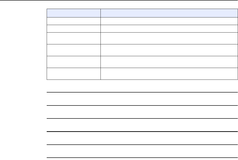
7368 ISAM CPE A-020W-A Product Guide Configure a A-020W-A
Issue: 01 3FE-47511-AAAA-TCZZA 57
2Choose a DNS server, Prefix Config, and Interface.
3Enter the DHCP configuration information.
4Enter the maximum and minimum intervals for RA messages.
5Click Save/Apply.
6STOP. This procedure is complete.
DHCP Start IP Address Enter the starting DHCP IP address.
DHCP End IP Address Enter the ending DHCP IP address.
Whether the address info
through DCHP
Select this check box to enable address information retrieval through DHCP.
Whether other info obtained
through DHCP
Select this check box to enable retrieval of other information through DHCP.
Maximum interval for
periodic RA messages
Enter the maximum interval (in seconds) for periodic Router Advertisement
messages. The interval range is from 4 to 1800.
Minimum interval for periodic
RA messages
Enter the minimum interval (in seconds) for periodic Router Advertisement
messages. The interval range is from 4 to 1800.
Field Description
(2 of 2)
Release 05.08.01 | June 2018 | Edition 01
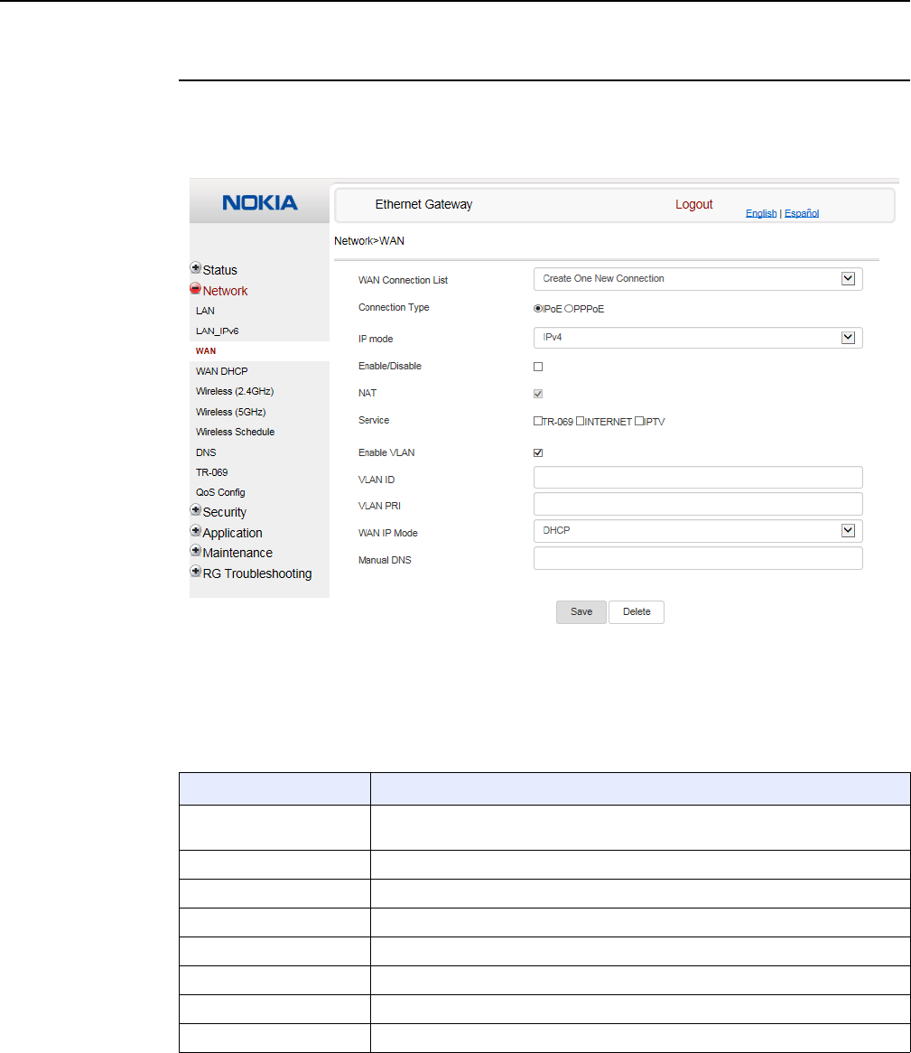
Configure a A-020W-A
58
7368 ISAM CPE A-020W-A Product Guide
3FE-47511-AAAA-TCZZA Issue: 01
Procedure 15 WAN networking configuration
1Select Network > WAN from the top-level menu in the Ethernet Gateway window, as shown
in Figure 19.
Figure 19 WAN window
Table 19 describes the fields in the WAN window.
Table 19 WAN parameters
Field Description
WAN Connection List Choose a WAN connection from the drop-down menu to set the connection
parameters
Connection Type Select a connection type: IPoE or PPPoE
IP Mode Choose an IP mode from the drop-down menu: IPv4 or IPv6
Enable/Disable Select this checkbox to enable the WAN connection
NAT Select this checkbox to enable NAT
Service Select the checkboxes to enable service types for this connection
Enable VLAN Select this checkbox to enable VLAN
VLAN ID Enter the VLAN ID
(1 of 2)
Release 05.08.01 | June 2018 | Edition 01
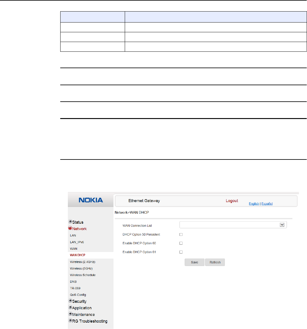
7368 ISAM CPE A-020W-A Product Guide Configure a A-020W-A
Issue: 01 3FE-47511-AAAA-TCZZA 59
2Configure a specific WAN connection.
3Click Save.
4STOP. This procedure is complete.
Procedure 16 WAN DHCP configuration
1Select Network > WAN DHCP from the top-level menu in the Ethernet Gateway window, as
shown in Figure 20.
Figure 20 WAN DHCP window
Table 20 describes the fields in the WAN DHCP window.
VLAN PRI Enter the VLAN PRI
WAN IP Mode Choose an IP mode from the drop-down menu
Manual DNS Enter a DNS
Field Description
(2 of 2)
Release 05.08.01 | June 2018 | Edition 01
Configure a A-020W-A
60
7368 ISAM CPE A-020W-A Product Guide
3FE-47511-AAAA-TCZZA Issue: 01
Table 20 WAN DHCP parameters
2Configure a WAN DHCP option.
3Click Save.
4STOP. This procedure is complete.
Field Description
WAN Connection List Choose a WAN connection from the drop-down menu
DHCP Option 50 persistent Select this checkbox to enable DHCP Option 50
Enable DHCP Option 60 Select this checkbox to enable DHCP Option 60 (vendor class identifier)
Enable DHCP Option 61 Select this checkbox to enable DHCP Option 61 (client identifier)
Release 05.08.01 | June 2018 | Edition 01
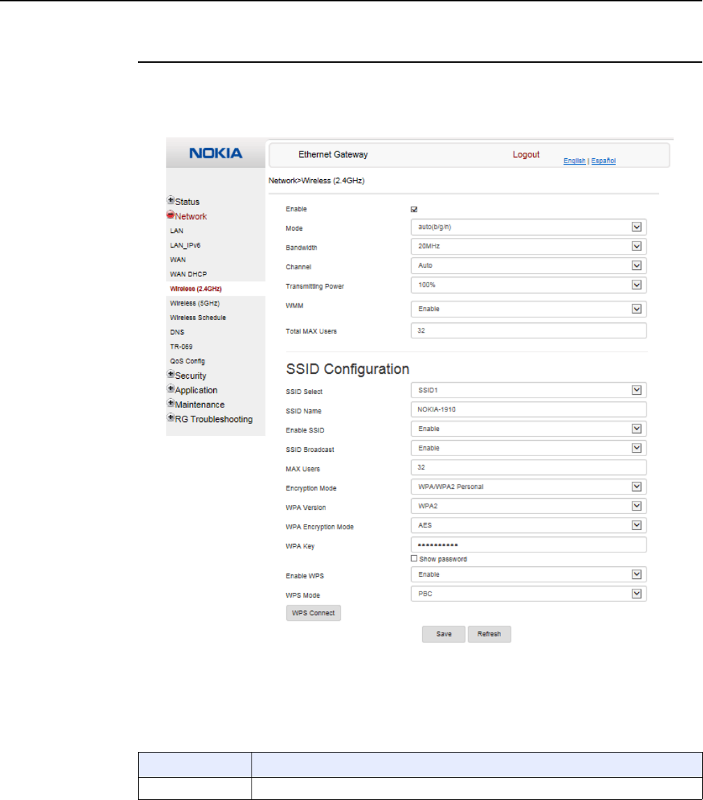
7368 ISAM CPE A-020W-A Product Guide Configure a A-020W-A
Issue: 01 3FE-47511-AAAA-TCZZA 61
Procedure 17 Wireless (2.4GHz) networking configuration
1Select Network > Wireless (2.4GHz) from the top-level menu in the Ethernet Gateway
window, as shown in Figure 21.
Figure 21 Wireless (2.4GHz) network window
Table 21 describes the fields in the Wireless 2.4GHz network window.
Table 21 Wireless 2.4GHz network parameters
Field Description
Enable Select this check box to enable WiFi
(1 of 2)
Release 05.08.01 | June 2018 | Edition 01

Configure a A-020W-A
62
7368 ISAM CPE A-020W-A Product Guide
3FE-47511-AAAA-TCZZA Issue: 01
2Configure the WiFi connection.
3If you have enabled and configured WPS, click WPS connect.
Mode Choose a WiFi mode from the drop-down menu:
•auto (b/g/n)
•b
•g
•n
•b/g
Bandwidth Choose 20 MHz or 40 MHz from the drop-down menu.
Channel Choose a channel from the drop-down menu or choose Auto to have the channel
automatically assigned
Transmitting Power Choose the percentage transmitting power from the drop-down menu
WMM Select this check box to enable or disable wireless multi media
Total MAX Users Enter the total number of MAX users
SSID Select Choose the SSID from the drop-down menu
SSID Name Enter the SSID name
Enable SSID Enable or disable SSID from this drop-down menu
SSID Broadcast Enable or disable SSID broadcast from this drop-down menu
MAX Users Enter the number of MAX users
Encryption Mode Choose an encryption mode from the drop-down menu:
•OPEN
•WEP
•WPA/WPA2 Personal
•WPA/WPA2 Enterprise
WPA Version Choose a WPA version from the drop-down menu:
•WPA1
•WPA2
•WPA1/WPA2
WPA Encryption
Mode
Choose a WPA encryption mode from the drop-down menu:
•TKIP
•AES
•TKIP/AES
WPA Key Enter the WPA key
Enable WPS Enable or disable WPS from this drop-down menu
WPS Mode Select a WPS mode from the drop-down menu: PBC (Push Button Connect) or PIN
(Personal Identification Number)
Field Description
(2 of 2)
Release 05.08.01 | June 2018 | Edition 01
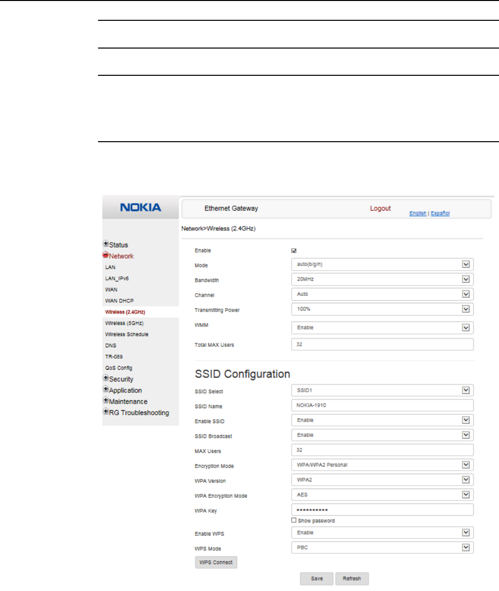
7368 ISAM CPE A-020W-A Product Guide Configure a A-020W-A
Issue: 01 3FE-47511-AAAA-TCZZA 63
4Click Save.
5STOP. This procedure is complete.
Procedure 18 Wireless (5GHz) networking configuration
1Select Network > Wireless (5GHz) from the top-level menu in the Ethernet Gateway window,
as shown in Figure 22.
Figure 22 Wireless (5GHz) network window
Release 05.08.01 | June 2018 | Edition 01

Configure a A-020W-A
64
7368 ISAM CPE A-020W-A Product Guide
3FE-47511-AAAA-TCZZA Issue: 01
Table 22 describes the fields in the Wireless 5GHz network window.
Table 22 Wireless 5GHz network parameters
Notes
(1) When Encryption Mode is set to “WPA/WPA2 Enterprise”, the following options are no longer available: WPA
version, WPA encryption mode, WPA key, Enable WPS, WPS mode.
(2) When Encryption Mode is set to “WPA/WPA2 Enterprise”, the following options become available: Primary
RADIUS server, port and password; Secondary RADIUS server, port, and password; RADIUS accounting port.
Field Description
Enable Select this check box to enable WiFi
Bandwidth Choose from:
•20 MHz
•40 MHz
•80 MHz
Channel Choose a channel from the drop-down menu or choose Auto to have the channel
automatically assigned
Transmitting Power Choose a percentage for the transmitting power from the drop-down menu:
•Low (20%)
•Medium (40%)
•High (60%)
•Maximum (100%)
WMM Select this check box to enable or disable wireless multi media
Enable MU-MIMO Choose Enable or disable MU-MIMO from this drop-down menu
The default is Enable, which enables users and wireless terminals to communicate with
each other.
MU-MIMO may decrease WiFi performance for clients who do not support it, in which
case Nokia recommends that you choose Disable.
Total MAX Users Enter the total number of MAX users
DFS re-entry Select this check box to enable or disable DFS re-entry
SSID Select Choose the SSID from the drop-down menu
SSID Name Change the name of the selected SSID
Enable SSID Choose Enable or disable SSID from this drop-down menu
SSID Broadcast Choose Enable or disable SSID broadcast from this drop-down menu
MAX Users Enter the number of MAX users
Encryption Mode Choose an encryption mode from the drop-down menu:
•OPEN
•WEP
•WPA/WPA2 Personal
•WPA/WPA2 Enterprise (1)(2)
WPA Key Enter the WPA key
Enable WPS Choose Enable or disable WPS from this drop-down menu
Release 05.08.01 | June 2018 | Edition 01
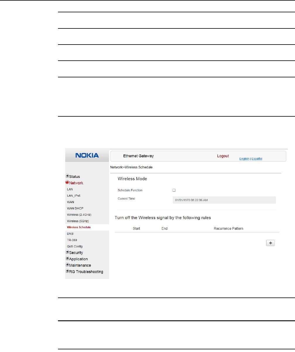
7368 ISAM CPE A-020W-A Product Guide Configure a A-020W-A
Issue: 01 3FE-47511-AAAA-TCZZA 65
2Configure the Wireless connection.
3If you have enabled and configured WPS, click WPS connect.
4Click Save.
5STOP. This procedure is complete.
Procedure 19 Wireless scheduling
1Select Network > Wireless Schedule from the top-level menu in the Ethernet Gateway
window, as shown in Figure 23.
Figure 23 Wireless Schedule window
2Select the Schedule Function check box to turn the wireless signal off for the configured
period.
3Click the plus sign (+) to add a scheduling rule.
A separate panel appears for configuring wireless schedule rules.
4Enter a start time and end time for the period in which you want the wireless signal off.
Release 05.08.01 | June 2018 | Edition 01
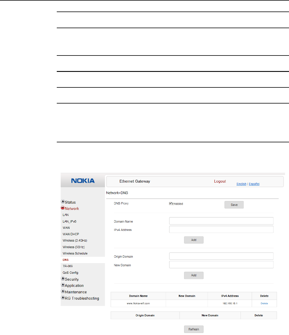
Configure a A-020W-A
66
7368 ISAM CPE A-020W-A Product Guide
3FE-47511-AAAA-TCZZA Issue: 01
5Choose Everyday or Individual Days from the drop-down menu.
6If you chose Individual Days, select the check boxes for the desired days.
The Recurrence Pattern shows the rules created to date.
7If desired, click the plus sign (+) to add more rules.
8Click Save Changes.
9STOP. This procedure is complete.
Procedure 20 DNS configuration
1Select Network > DNS from the top-level menu in the Ethernet Gateway window, as shown
in Figure 24.
Figure 24 DNS network window
Release 05.08.01 | June 2018 | Edition 01
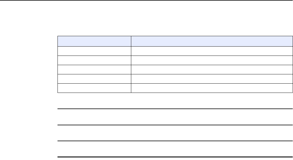
7368 ISAM CPE A-020W-A Product Guide Configure a A-020W-A
Issue: 01 3FE-47511-AAAA-TCZZA 67
Table 23 describes the fields in the DNS network window.
Table 23 DNS network parameters
2Enter the domain name and IP address and click Add.
3If required, associate an origin domain with a new domain, click Add.
4STOP. This procedure is complete.
Field Description
DNS Proxy Select this check box to enable DNS proxy
Domain Name Domain name
IPv4 Address Domain IP address
Origin Domain Origin domain name
New Domain New domain name
Release 05.08.01 | June 2018 | Edition 01
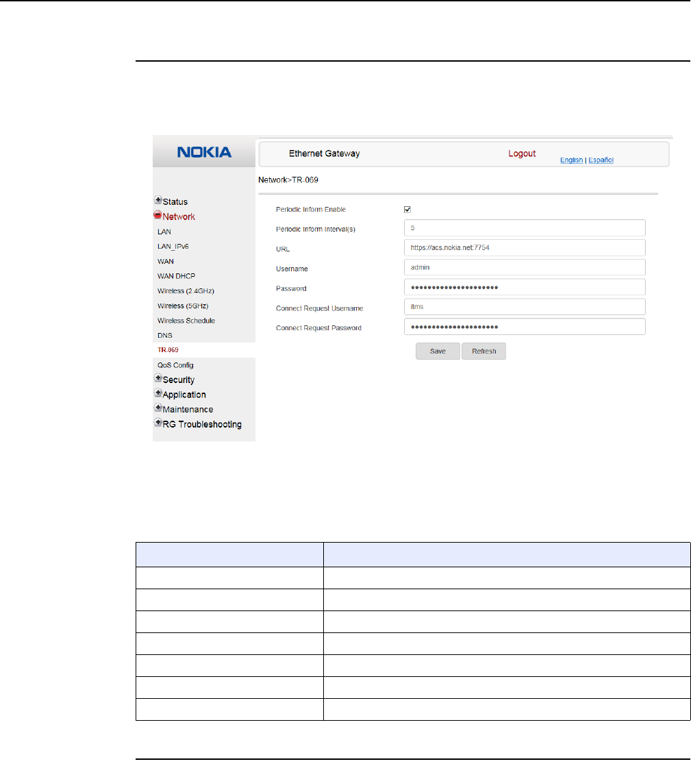
Configure a A-020W-A
68
7368 ISAM CPE A-020W-A Product Guide
3FE-47511-AAAA-TCZZA Issue: 01
Procedure 21 TR-069 configuration
1Select Network > TR-069 from the top-level menu in the Ethernet Gateway window, as
shown in Figure 25.
Figure 25 TR-069 network window
Table 24 describes the fields in the TR-069 network window.
Table 24 TR-069 network parameters
2Configure TR-069 by entering the required information.
Field Description
Periodic Inform Enable Select this check box to enable periodic inform updates
Periodic Inform Interval(s) Time between periodic inform updates, in seconds
URL URL of the auto-configuration server
Username Username used to log in to the A-020W-A CPE
Password Password used to log in to the A-020W-A CPE
Connect Request Username Username used to log in to the auto-configuration server
Connect Request Password Password used to log in to the auto-configuration server
Release 05.08.01 | June 2018 | Edition 01
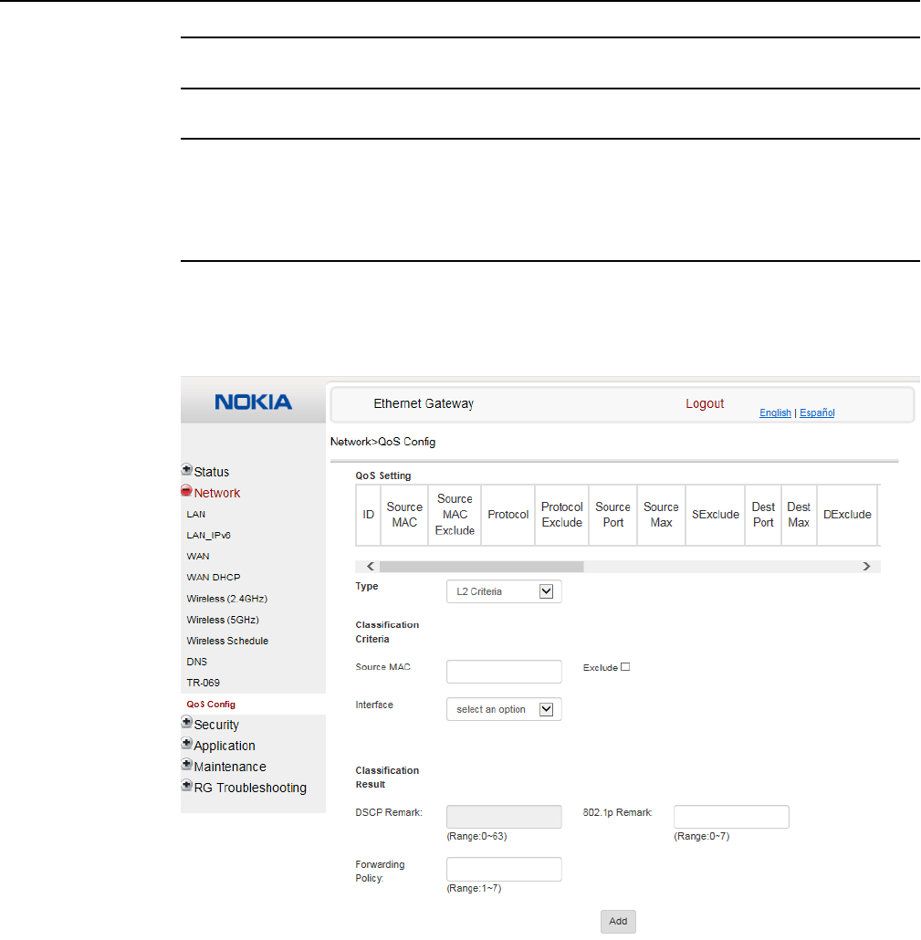
7368 ISAM CPE A-020W-A Product Guide Configure a A-020W-A
Issue: 01 3FE-47511-AAAA-TCZZA 69
3Click Save.
4STOP. This procedure is complete.
Procedure 22 QoS configuration
1Select Network > QoS Config from the top-level menu in the Ethernet Gateway window.
Figure 26 shows the window for configuring QoS L2 (Layer 2 packet sizes).
Figure 26 QoS Config window (L2)
Figure 27 shows the window for configuring QoS L3 (Layer 3 packet sizes).
Release 05.08.01 | June 2018 | Edition 01
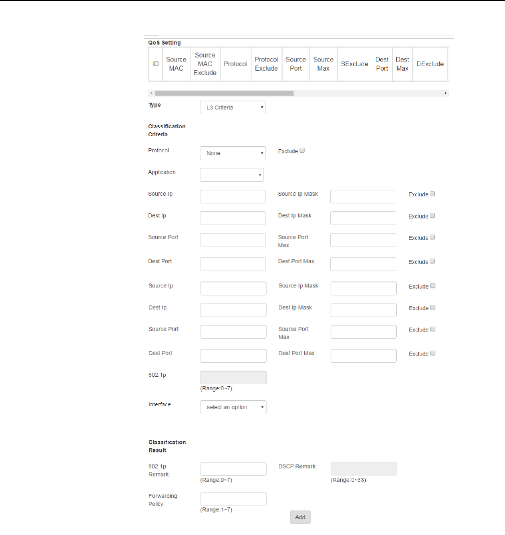
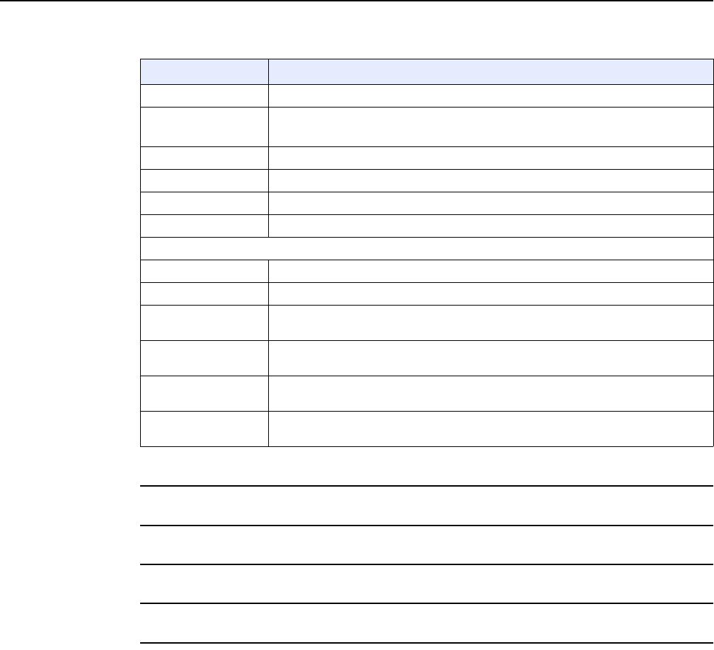
7368 ISAM CPE A-020W-A Product Guide Configure a A-020W-A
Issue: 01 3FE-47511-AAAA-TCZZA 71
Table 25 QoS Config parameters
2Choose a QoS type from the drop-down menu: L2 or L3.
3Configure a QoS policy.
4Click Add to add a QoS policy.
5STOP. This procedure is complete.
8.1.4 Security configuration
The A-020W-A CPE also supports security configuration, including:
•firewall
•MAC filter
•IP filter
•URL filter
Field Description
Type Choose a QoS service layer type from the drop-down menu, either L2 or L3.
Source MAC Enter the source MAC.
Select the Exclude check box to exclude the source MAC
Interface Choose an interface from the drop-down menu
DSCP Remark Enter the value for the DSCP mark (range: 0-63); valid only for L3 Criteria
802.1p Mark Enter the value for the 802.1p (range: 0-7)
Forwarding Policy Enter the number for the forwarding policy (range: 1-7)
Additional fields for L3
Protocol Choose a protocol from the drop-down menu, or select the Exclude check box
Application Choose an application from the drop-down menu
Source IP and
Source IP Mask
Enter the values for the source IP and IP mask, or select the Exclude check box
Destination IP and
Destination IP Mask
Enter the values for the destination IP and IP mask, or select the Exclude check box
Source Port and
Source Port Max
Enter the values for the source port and port max (highest port number) or select the
Exclude check box
Destination Port and
Destination Port Max
Enter the values for the destination port and port max (highest port number), or select
the Exclude check box
Release 05.08.01 | June 2018 | Edition 01
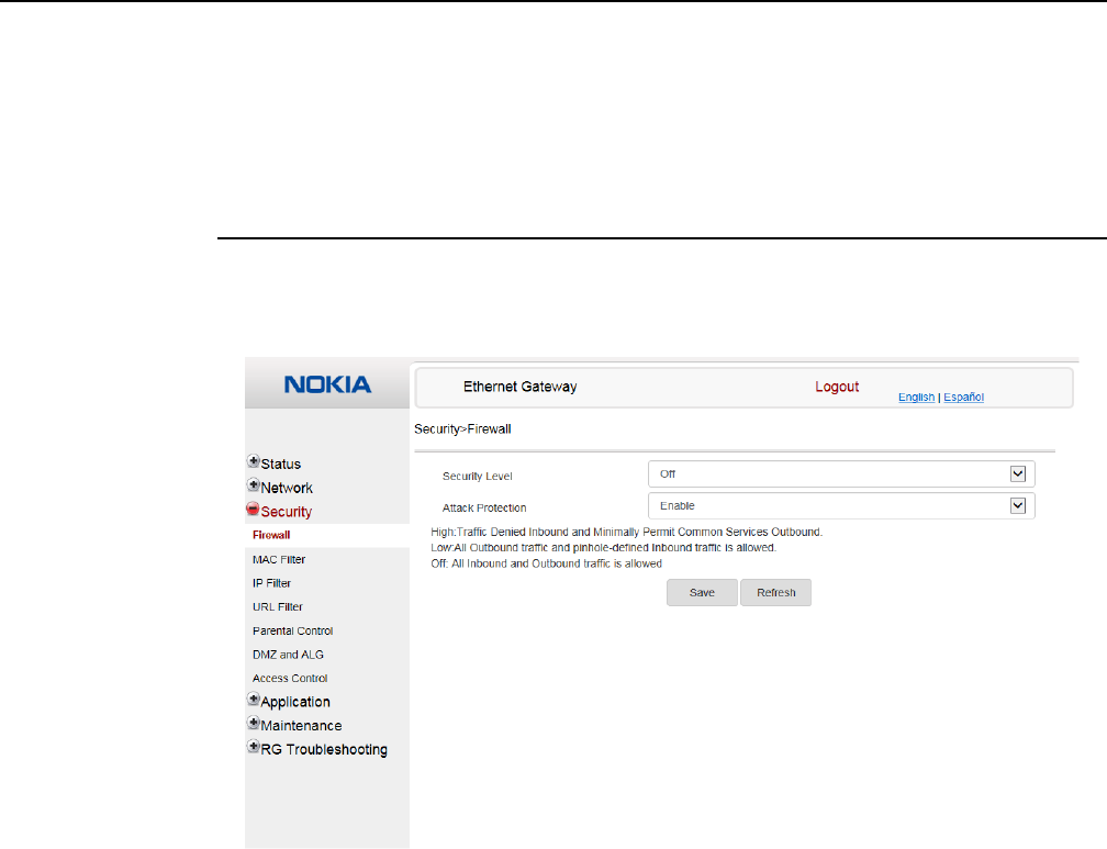
Configure a A-020W-A
72
7368 ISAM CPE A-020W-A Product Guide
3FE-47511-AAAA-TCZZA Issue: 01
•parental control
•DMZ and ALG
•access control
Procedure 23 Firewall configuration
1Select Security > Firewall from the top-level menu in the Ethernet Gateway window, as
shown in Figure 28.
Figure 28 Firewall window
Firewall security applies only to services provided by the A-020W-A CPE. Internet access
from the LAN side is not affected by this firewall.
Three security levels are available: Off, Low, and High.
At the Off level, no firewall security is in effect,
At the Low level, pre-routing is supported: port forwarding, DMZ, host application, and host
drop. Also supported are application services: DDNS, DHCP, DNS, H248, IGMP, NTP client,
SSH, Telnet, TFTP, TR-069, and VoIP. The following types of ICMP messages are permitted:
echo request and reply, destination unreachable, and TTL exceeded. Other types of ICMP
messages are blocked. DNS proxy is supported from LAN to WAN but not from WAN to LAN.
At the High level, pre-routing and application services are not supported. UDP Port 8000 can
be used to access the services, for example FTP can use 8021 and Telnet can use 8023.
Regular UDP cannot be used. RG access is permitted via the LAN side but not via the WAN
side.
Release 05.08.01 | June 2018 | Edition 01

7368 ISAM CPE A-020W-A Product Guide Configure a A-020W-A
Issue: 01 3FE-47511-AAAA-TCZZA 73
Table 26 describes the fields in the firewall window.
Table 26 Firewall parameters
2Configure the firewall.
3Click Save.
4STOP. This procedure is complete.
Field Description
Security level Choose the security level from the drop-down menu: Off, Low, or High
Attack Protect
(Protection against
DoS or DDoS attacks)
Choose enable or disable attack protect from the drop-down menu
The default is disable
Release 05.08.01 | June 2018 | Edition 01
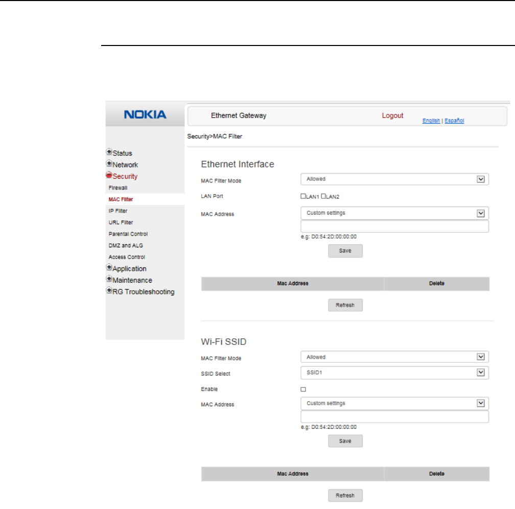
Configure a A-020W-A
74
7368 ISAM CPE A-020W-A Product Guide
3FE-47511-AAAA-TCZZA Issue: 01
Procedure 24 MAC filter configuration
1Select Security > MAC Filter from the top-level menu in the Ethernet Gateway window, as
shown in Figure 29.
Figure 29 MAC filter window
Table 27 describes the fields in the MAC filter window.
Release 05.08.01 | June 2018 | Edition 01

7368 ISAM CPE A-020W-A Product Guide Configure a A-020W-A
Issue: 01 3FE-47511-AAAA-TCZZA 75
Table 27 MAC filter parameters
2Configure a MAC filter for the Ethernet interface.
3Click Save.
4If desired, select a MAC address and click the Delete column to delete a MAC address.
5Click Refresh to update the information.
6Configure a MAC filter for WiFi SSID (WLAN MAC filter).
7Click Save.
8STOP. This procedure is complete.
Field Description
Ethernet Interface MAC filter
MAC Filter Mode Choose the MAC filter mode from this drop-down menu: Blocked or Allowed
LAN Port Select the check boxes for the LAN ports
MAC Address Choose a MAC address from the drop-down menu or enter the address in the text field
WiFi SSID (WLAN) MAC filter
MAC Filter Mode Choose the MAC filter mode from this drop-down menu: Blocked or Allowed
SSID Select Choose an SSID option from the drop-down menu
Enable Select this check box to enable MAC filtering for WiFi SSID
MAC Address Choose a MAC address from the drop-down menu or enter the address in the text field
Release 05.08.01 | June 2018 | Edition 01
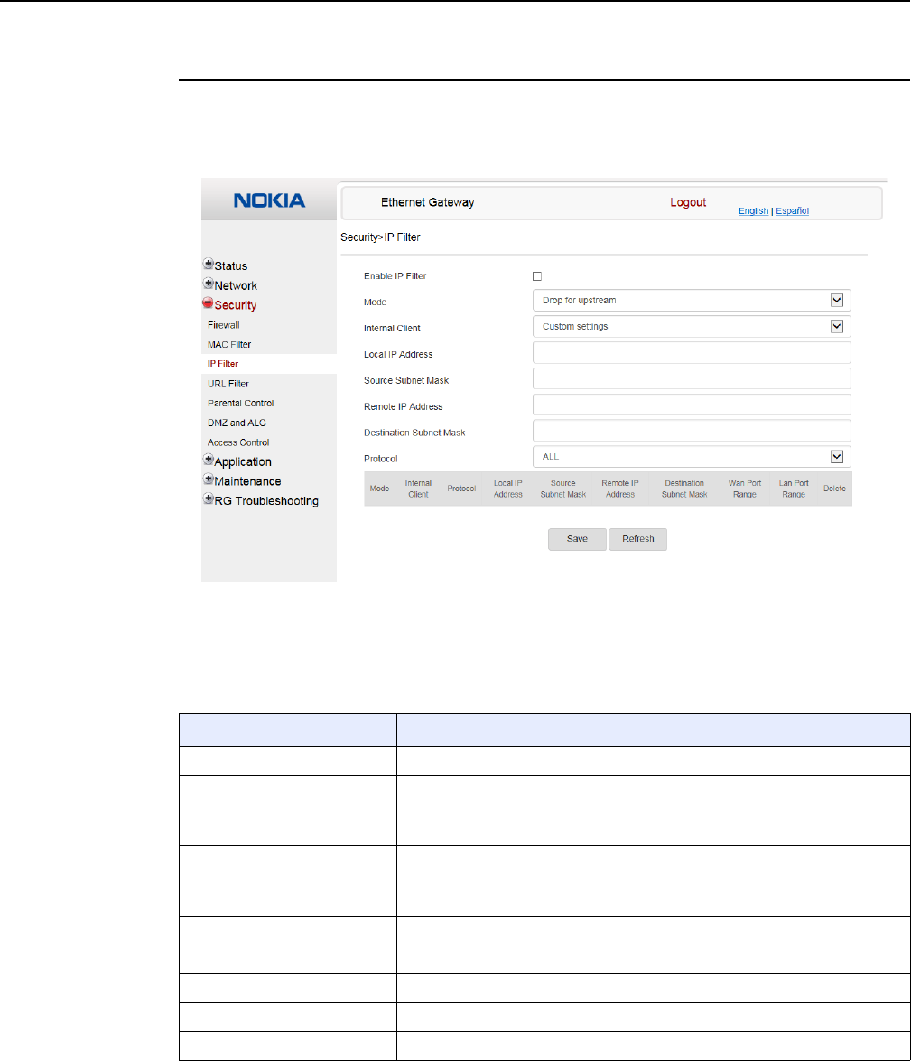
Configure a A-020W-A
76
7368 ISAM CPE A-020W-A Product Guide
3FE-47511-AAAA-TCZZA Issue: 01
Procedure 25 IP filter configuration
1Select Security > IP filter from the top-level menu in the Ethernet Gateway window, as shown
in Figure 30.
Figure 30 IP filter window
Table 28 describes the fields in the IP filter window.
Table 28 IP filter parameters
Field Description
Enable IP Filter Select this check box to enable an IP filter
Mode Choose an IP filter mode from the drop-down menu:
•Drop for upstream
•Drop for downstream
Internal Client Choose an internal client from the drop-down menu:
•Customer setting - uses the IP address input below
•IP - uses the connecting devices' IP to the device
Local IP Address Local IP address
Source Subnet Mask Source subnet mask
Remote IP Address Remote IP address
Destination Subnet Mask Destination subnet mask
Protocol Choose an application protocol or all from the drop-down menu
Release 05.08.01 | June 2018 | Edition 01
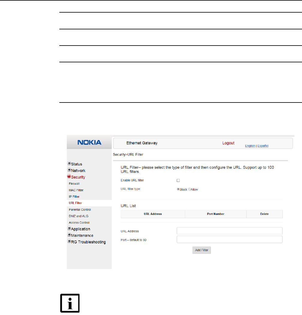
7368 ISAM CPE A-020W-A Product Guide Configure a A-020W-A
Issue: 01 3FE-47511-AAAA-TCZZA 77
2Configure the IP filter.
3Click Add.
4STOP. This procedure is complete.
Procedure 26 URL filter configuration
1Select Security > URL Filter from the top-level menu in the Ethernet Gateway window, as
shown in Figure 31.
Figure 31 URL Filter window
Table 29 describes the fields in the URL Filter window.
Note — You cannot use URL filtering for HTTPS. The URL is encrypted
when using HTTPS.
Release 05.08.01 | June 2018 | Edition 01
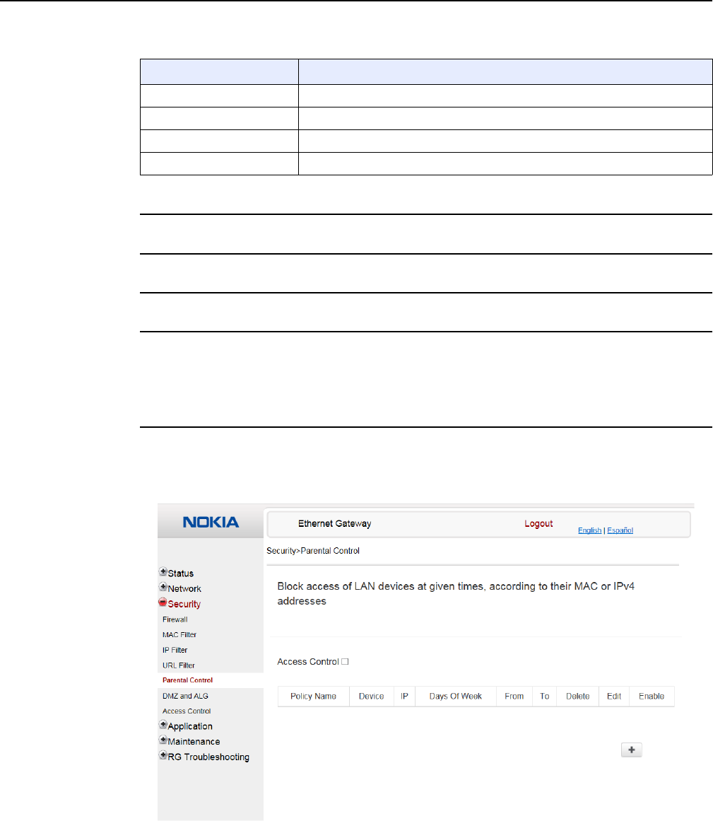
Configure a A-020W-A
78
7368 ISAM CPE A-020W-A Product Guide
3FE-47511-AAAA-TCZZA Issue: 01
Table 29 URL Filter parameters
2Configure the URL Filter.
3Click Add Filter.
4STOP. This procedure is complete.
Procedure 27 Parental control
1Select Security > Parent Control from the top-level menu in the Ethernet Gateway window,
as shown in Figure 32.
Figure 32 Parental Control window
Field Description
Enable URL filter Select the check box to enable the URL filter
URL filter type Select the radio button for Exclude URL or Include URL
URL Address Enter the URL address
Port Enter the port number; the default is 80
Release 05.08.01 | June 2018 | Edition 01

7368 ISAM CPE A-020W-A Product Guide Configure a A-020W-A
Issue: 01 3FE-47511-AAAA-TCZZA 79
Table 30 describes the fields in the Parental Control window.
Table 30 Parental control parameters
2Select the Access Control check box.
3Click the plus sign (+) to add a policy.
A separate panel appears for configuring the policy name, IP address of the device, and
dates and times for the policy.
4Configure the parental control policy.
5Click Enable to activate the policy.
6STOP. This procedure is complete.
Field Description
Policy Name Enter a name for the parental control policy or choose a policy from the list
Device The device for which the rule will apply
IP Enter the IPv4 address for the device or choose an IPv4 address from the list
Days of the week Choose Every Day, or Individual Days and select the check boxes for the days of the week
for which the policy applies
From/To Enter the times for the policy to be in effect
Release 05.08.01 | June 2018 | Edition 01
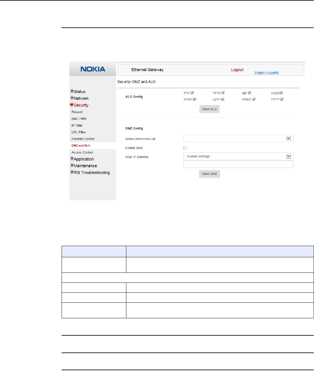
Configure a A-020W-A
80
7368 ISAM CPE A-020W-A Product Guide
3FE-47511-AAAA-TCZZA Issue: 01
Procedure 28 DMZ and ALG configuration
1Select Security > DMZ and ALG from the top-level menu in the Ethernet Gateway window,
as shown in Figure 33.
Figure 33 DMZ and ALG window
Table 31 describes the fields in the DMZ and ALG window.
Table 31 DMZ and ALG parameters
2Configure ALG.
3Click Save ALG.
4Configure DMZ.
Field Description
ALG Config Select the check boxes to enable the protocols to be supported by the ALG: FTP,
TFTP, SIP, H323, RTSP, L2TP, IPSEC, PPTP
DMZ Config
WAN Connection List Choose a WAN connection from the drop-down menu
Enable DMZ Select this check box to enable DMZ on the chosen WAN connection
DMZ IP Address Choose Customer Setting and enter the DMZ IP address or choose the IP address
of a connected device from the drop-down menu
Release 05.08.01 | June 2018 | Edition 01
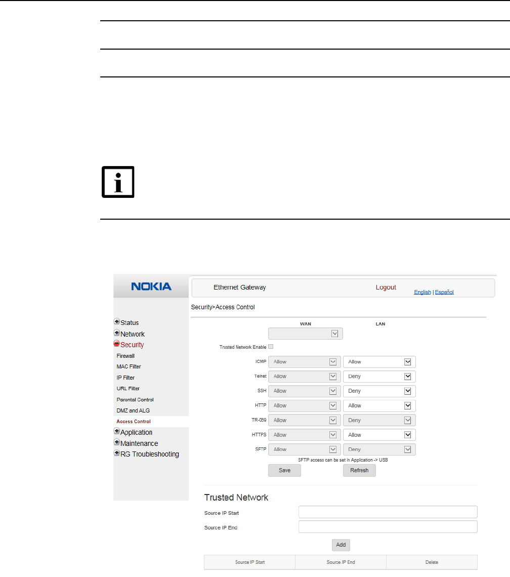
7368 ISAM CPE A-020W-A Product Guide Configure a A-020W-A
Issue: 01 3FE-47511-AAAA-TCZZA 81
5Click Save DMZ.
6STOP. This procedure is complete.
Procedure 29 Access control configuration
This procedure describes how to configure the access control level (ACL).
1Select Security > Access Control from the top-level menu in the Ethernet Gateway window,
as shown in Figure 34.
Figure 34 Access Control window
Table 32 describes the fields in the Access Control window.
Note 1 — ACL takes precedence over the firewall policy.
Note 2 — The trusted network object will be shared for all WAN
connections; it is not applied individually to a WAN connection.
Release 05.08.01 | June 2018 | Edition 01

Configure a A-020W-A
82
7368 ISAM CPE A-020W-A Product Guide
3FE-47511-AAAA-TCZZA Issue: 01
Table 32 Access control parameters
2Select a WAN connection from the drop-down menu.
3Click to enable or disable Trusted Network.
4Select an access control level for each of the six protocols: ICMP, Telnet, SSH, HTTP,
TR-069, and HTTPS for both the WAN and the LAN side.
5Click Save.
6Optionally, add one or more subnet trusted networks.
The maximum number of entries is 32.
You can also use the Source IP fields to delete a previously created entry for a subnet trusted
network.
7STOP. This procedure is complete.
8.1.5 Application configuration
The A-020W-A CPE also supports application configuration, including:
•port forwarding
•port triggering
•DDNS
•NTP
•UPnP and DLNA
Field Description
WAN Choose a connection from the drop-down menu
Trusted Network Enable Click to enable or disable
ICMP, Telnet, SSH, HTTP, TR-069,
HTTPS
Select an access control level for each protocol:
WAN side: Allow, Deny, or Trusted Network Only
LAN side: Allow or Deny
Source IP Start Enter a start IP address for the new subnet trusted network
Source IP End Enter an end IP address for the new subnet trusted network
Release 05.08.01 | June 2018 | Edition 01
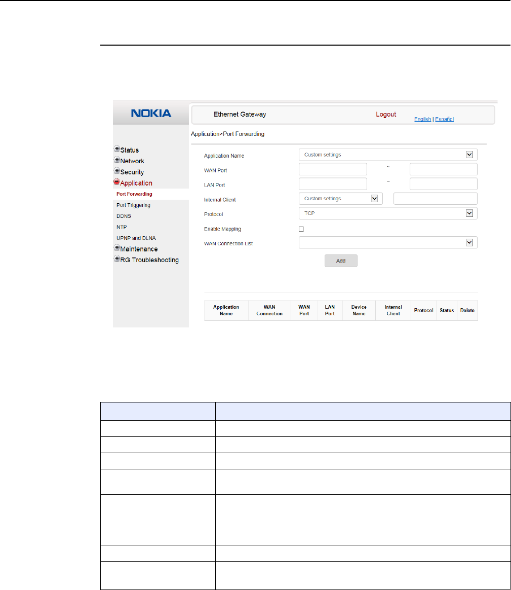
7368 ISAM CPE A-020W-A Product Guide Configure a A-020W-A
Issue: 01 3FE-47511-AAAA-TCZZA 83
Procedure 30 Port forwarding configuration
1Select Application > Port forwarding from the top-level menu in the Ethernet Gateway
window, as shown in Figure 35.
Figure 35 Port forwarding window
Table 33 describes the fields in the port forwarding window.
Table 33 Port forwarding parameters
Field Description
Application Name Choose an application name from the drop-down menu
WAN Port WAN port range
LAN Port LAN port range
Internal Client Choose a connected device from the drop-down menu and enter the associated
IP address
Protocol Choose the port forwarding protocol from the drop-down menu:
•TCP
•UDP
•TCP/UDP
Enable Mapping Select this check box to enable mapping
WAN Connection List Choose a WAN connection from the drop-down menu
Note: only active devices are shown on this menu
Release 05.08.01 | June 2018 | Edition 01
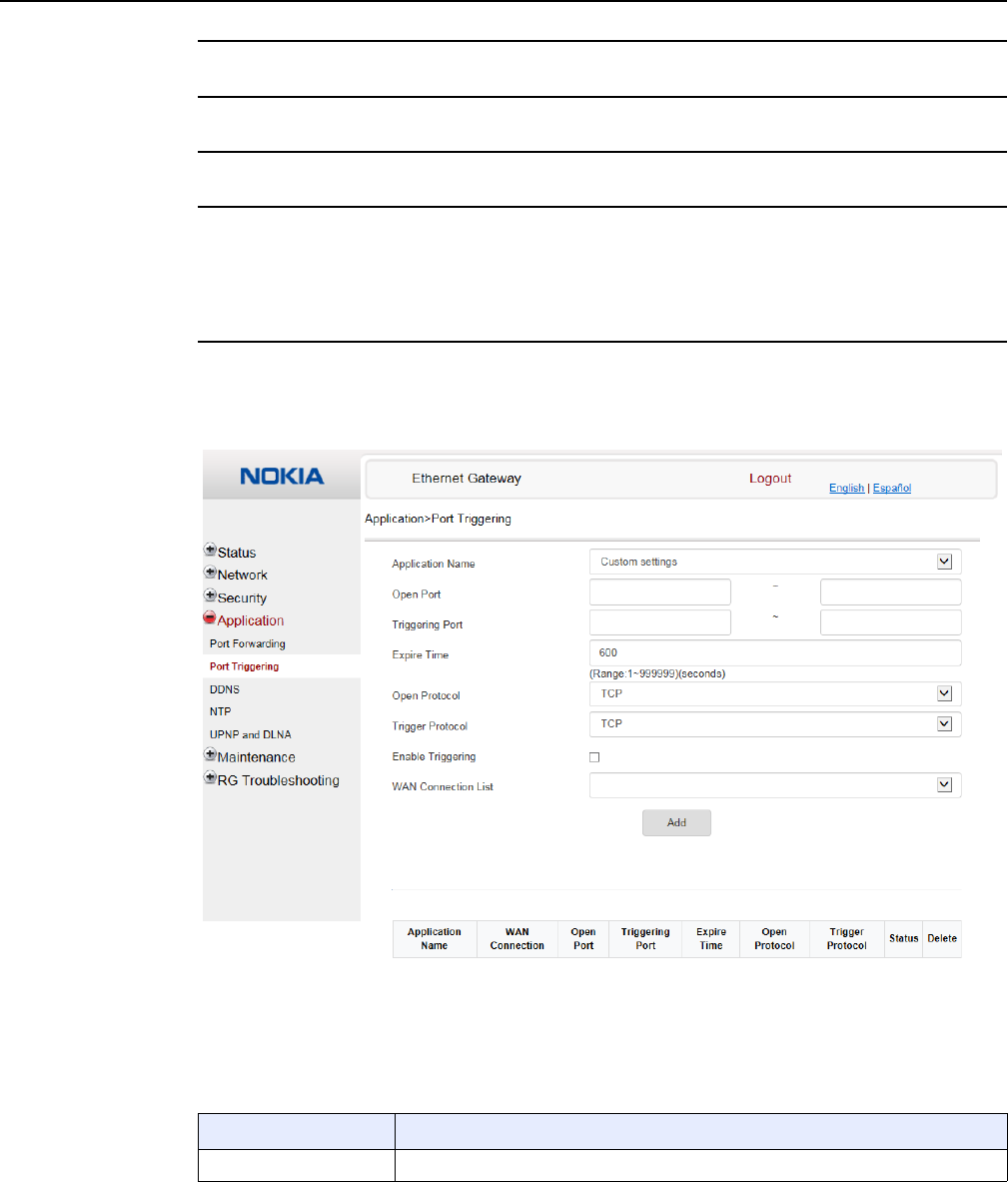
Configure a A-020W-A
84
7368 ISAM CPE A-020W-A Product Guide
3FE-47511-AAAA-TCZZA Issue: 01
2Configure port forwarding.
3Click Add.
4STOP. This procedure is complete.
Procedure 31 Port triggering
1Select Application > Port Triggering from the top-level menu in the Ethernet Gateway
window, as shown in Figure 36.
Figure 36 Port Triggering window
Table 33 describes the fields in the Port Triggering window.
Table 34 Port triggering parameters
Field Description
Application Name Choose an application name from the drop-down menu
(1 of 2)
Release 05.08.01 | June 2018 | Edition 01
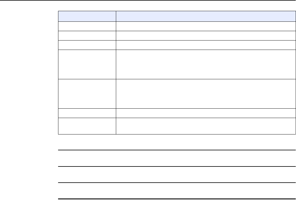
7368 ISAM CPE A-020W-A Product Guide Configure a A-020W-A
Issue: 01 3FE-47511-AAAA-TCZZA 85
2Configure port triggering.
3Click Add.
4STOP. This procedure is complete.
Open Port Enter the open port range
Triggering Port Enter the triggering port range
Expire Time Enter the expiration time in seconds
Open Protocol Choose the open port protocol from the drop-down menu:
•TCP
•UDP
•TCP/UDP
Trigger Protocol Choose the triggering port protocol from the drop-down menu:
•TCP
•UDP
•TCP/UDP
Enable Triggering Select this check box to enable port triggering
WAN Connection List Choose a WAN connection from the drop-down menu
Note: only active devices are shown on this menu
Field Description
(2 of 2)
Release 05.08.01 | June 2018 | Edition 01
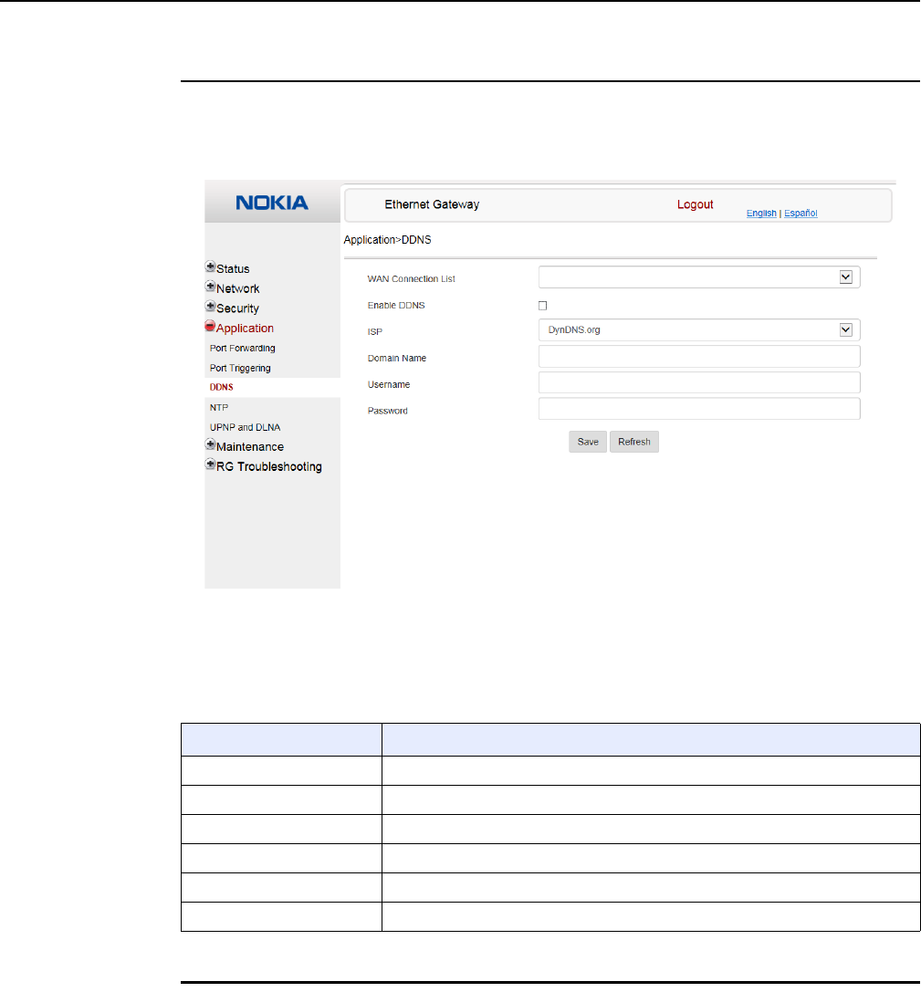
Configure a A-020W-A
86
7368 ISAM CPE A-020W-A Product Guide
3FE-47511-AAAA-TCZZA Issue: 01
Procedure 32 DDNS configuration
1Select Application > DDNS from the top-level menu in the Ethernet Gateway window, as
shown in Figure 37.
Figure 37 DDNS window
Table 35 describes the fields in the DDNS window.
Table 35 DDNS parameters
2Configure DDNS.
Field Description
WAN Connection List Choose a WAN connection from the drop-down menu
Enable DDNS Select this check box to enable DDNS on the chosen WAN connection
ISP Choose an ISP from the drop-down menu.
Domain Name Enter the domain name for the DDNS server
Username Enter the DDNS username
Password Enter the DDNS password
Release 05.08.01 | June 2018 | Edition 01
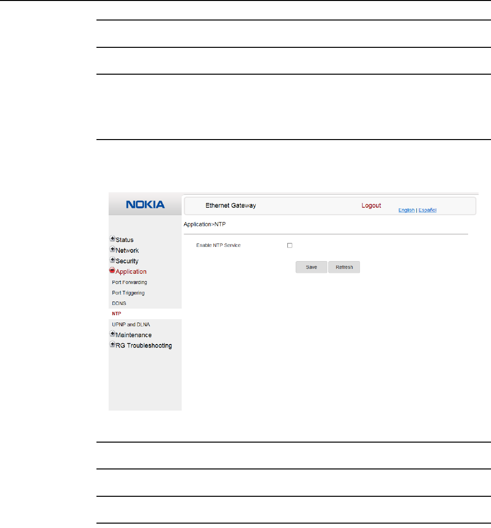
7368 ISAM CPE A-020W-A Product Guide Configure a A-020W-A
Issue: 01 3FE-47511-AAAA-TCZZA 87
3Click Save.
4STOP. This procedure is complete.
Procedure 33 NTP configuration
1Select Application > NTP from the top-level menu in the Ethernet Gateway window, as shown
in Figure 38.
Figure 38 NTP window
2Select the Enable NTP Service check box.
3Click Save.
4STOP. This procedure is complete.
Release 05.08.01 | June 2018 | Edition 01
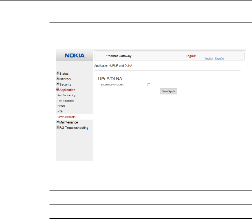
Configure a A-020W-A
88
7368 ISAM CPE A-020W-A Product Guide
3FE-47511-AAAA-TCZZA Issue: 01
Procedure 34 UPnP and DLNA configuration
1Select Application > UPnP and DLNA from the top-level menu in the Ethernet Gateway
window, as shown in Figure 39.
Figure 39 UPnP and DLNA window
2Select the Enable UPnP check box to enable UPnP.
3Click Save/Apply.
4STOP. This procedure is complete.
8.1.6 Maintenance
The A-020W-A CPE supports maintenance tasks, including:
•password change
•device management
•backup and restore
•firmware upgrade
•device reboot
Release 05.08.01 | June 2018 | Edition 01

7368 ISAM CPE A-020W-A Product Guide Configure a A-020W-A
Issue: 01 3FE-47511-AAAA-TCZZA 89
•restore factory defaults
•diagnostics
•log
Procedure 35 Password configuration
A password must adhere to the following password rules:
•the password may consist of uppercase letters, lowercase letters, digital numbers, and
the following special characters ! # + , - / @ _ : = ]
•the password length must be from 8 to 24 characters
•the first character must be a digital number or a letter
•the password must contain at least two types of characters: numbers, letters, or special
characters
•the same character must not appear more than 8 times in a row
When the password meets the password rules, the application displays the message “Your
password has been changed successfully”.
When the password does not meet the password rules, the application displays a message to
indicate which password rule has not been followed, for example:
•the password is too short
•the password is too long
Release 05.08.01 | June 2018 | Edition 01
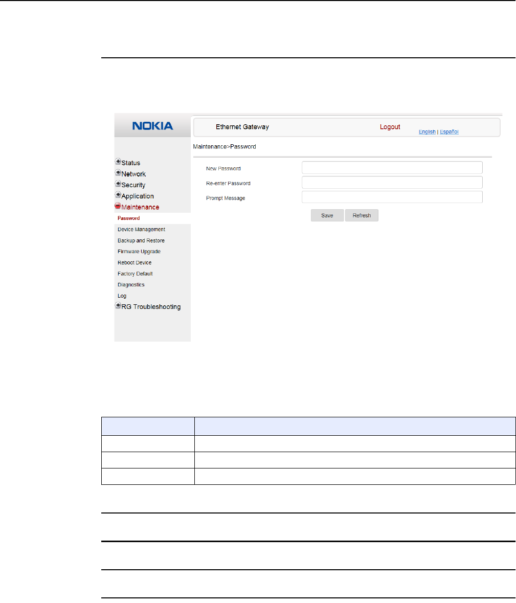
Configure a A-020W-A
90
7368 ISAM CPE A-020W-A Product Guide
3FE-47511-AAAA-TCZZA Issue: 01
•the first character cannot be a special character
•there are not enough character classes
1Select Maintenance > Password from the top-level menu in the GPON Home Gateway
window, as shown in Figure 40.
Figure 40 Password window
Table 36 describes the fields in the password window.
Table 36 Password parameters
2Configure the new password.
3Click Save.
4STOP. This procedure is complete.
Field Description
New Password New password (must adhere to the password rules described above)
Re-enter Password Must match the new password entered above exactly
Prompt Message Password prompt message
Release 05.08.01 | June 2018 | Edition 01
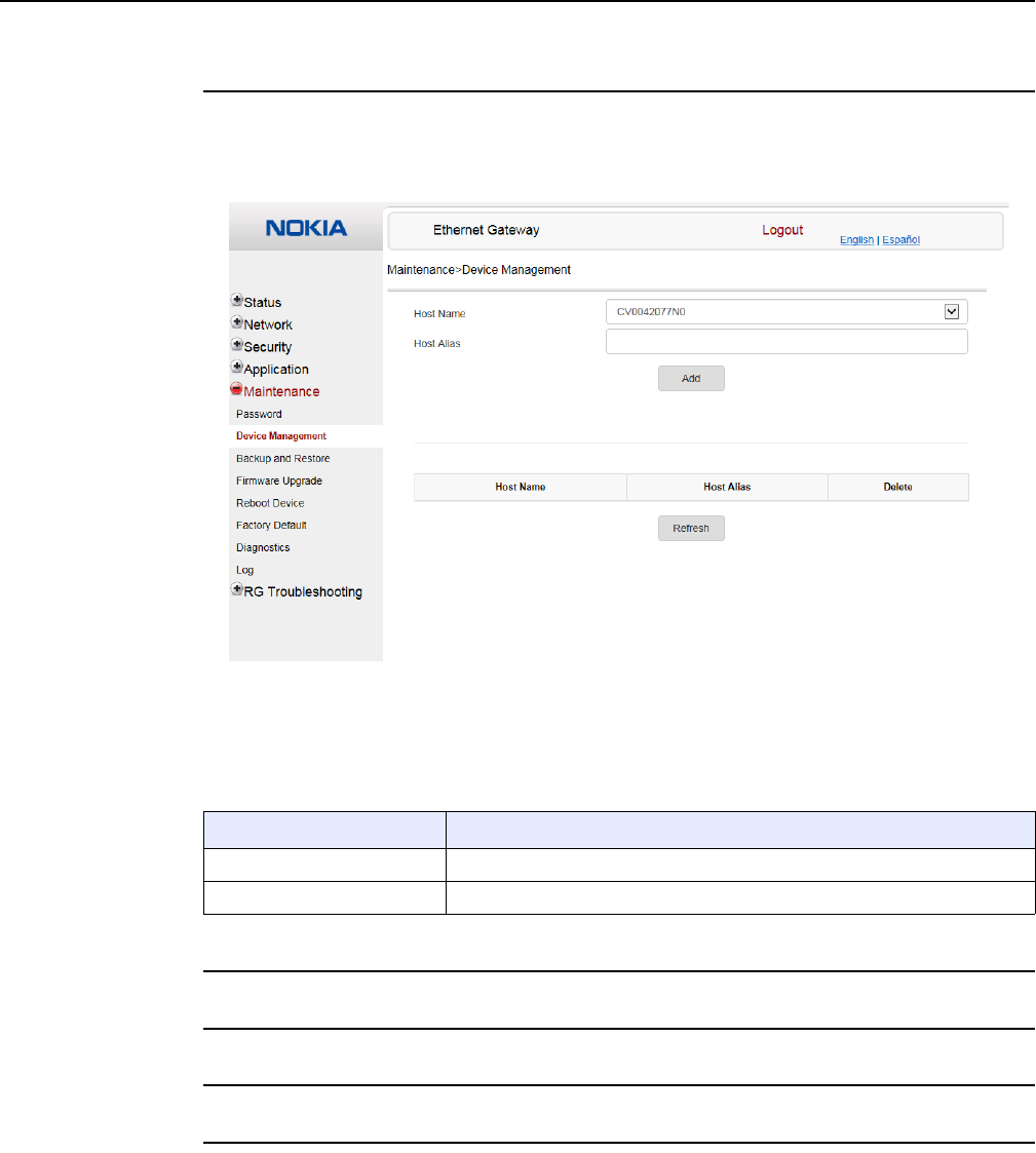
7368 ISAM CPE A-020W-A Product Guide Configure a A-020W-A
Issue: 01 3FE-47511-AAAA-TCZZA 91
Procedure 36 Device management
1Select Maintenance > Device Management from the top-level menu in the Ethernet Gateway
window, as shown in Figure 41.
Figure 41 Device Management window
Table 37 describes the fields in the Device Management window.
Table 37 Device Management parameters
2Configure an alias for a specific host.
3Click Add.
4STOP. This procedure is complete.
Field Description
Host Name Choose a host from the drop-down menu
Host Alias Enter an alias for the chosen host
Release 05.08.01 | June 2018 | Edition 01
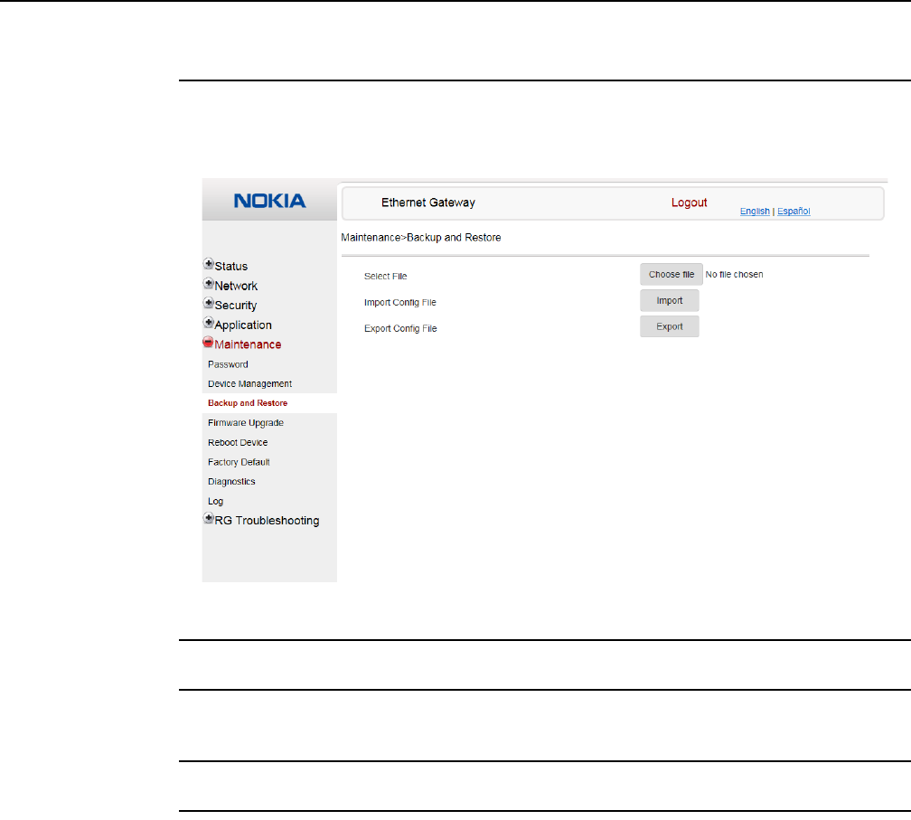
Configure a A-020W-A
92
7368 ISAM CPE A-020W-A Product Guide
3FE-47511-AAAA-TCZZA Issue: 01
Procedure 37 Backup and Restore
1Select Maintenance > Backup and Restore from the top-level menu in the Ethernet Gateway
window, as shown in Figure 42.
Figure 42 Backup and Restore window
2Click Select File and choose the backup file.
3Click Import Config File to restore the A-020W-A CPE to the saved backup or click Export
Config File to export the current configuration to the backup file.
4STOP. This procedure is complete.
Release 05.08.01 | June 2018 | Edition 01
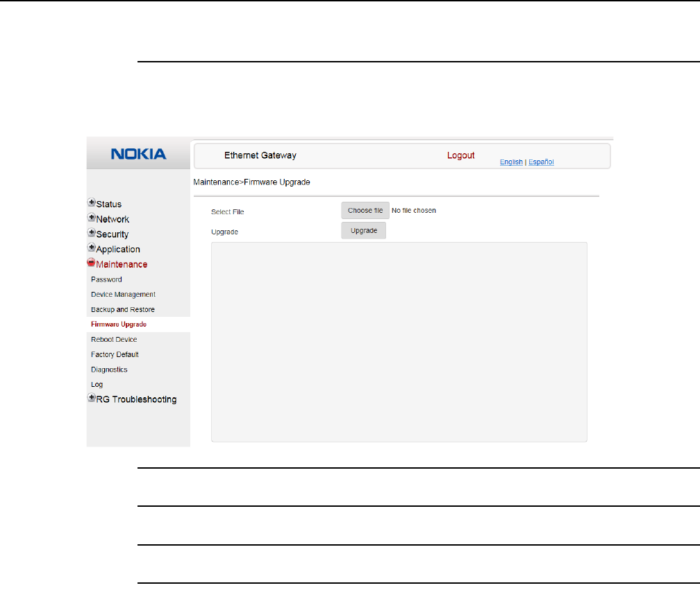
7368 ISAM CPE A-020W-A Product Guide Configure a A-020W-A
Issue: 01 3FE-47511-AAAA-TCZZA 93
Procedure 38 Upgrade firmware
1Select Maintenance > Firmware Upgrade from the top-level menu in the Ethernet Gateway
window, as shown in Figure 43.
Figure 43 Firmware Upgrade window
2Click Select File and choose the new firmware file.
3Click Upgrade to upgrade the firmware.
4STOP. This procedure is complete.
Release 05.08.01 | June 2018 | Edition 01
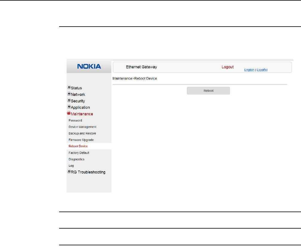
Configure a A-020W-A
94
7368 ISAM CPE A-020W-A Product Guide
3FE-47511-AAAA-TCZZA Issue: 01
Procedure 39 Reboot
1Select Maintenance > Reboot Device from the top-level menu in the Ethernet Gateway
window, as shown in Figure 44.
Figure 44 Reboot Device window
2Click Reboot to reboot the A-020W-A CPE.
3STOP. This procedure is complete.
Release 05.08.01 | June 2018 | Edition 01
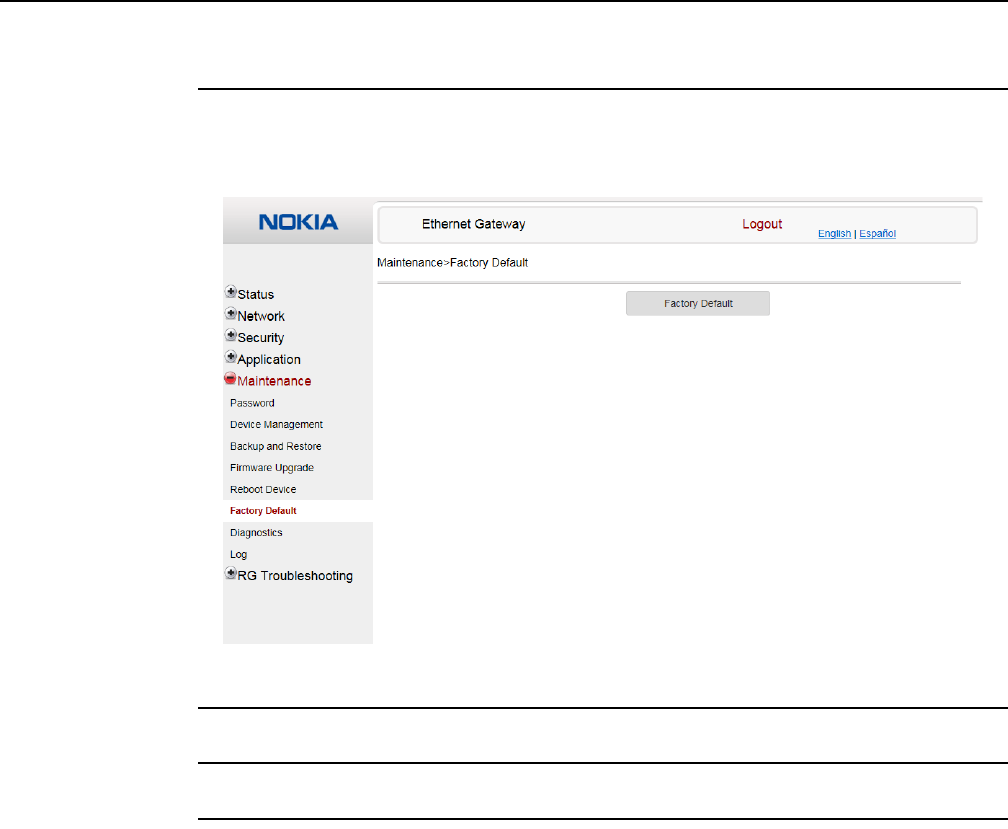
7368 ISAM CPE A-020W-A Product Guide Configure a A-020W-A
Issue: 01 3FE-47511-AAAA-TCZZA 95
Procedure 40 Restore factory defaults
1Select Maintenance > Factory Default from the top-level menu in the Ethernet Gateway
window, as shown in Figure 45.
Figure 45 Factory Default window
2Click Factory Default to reset the A-020W-A CPE to its factory default settings.
3STOP. This procedure is complete.
Release 05.08.01 | June 2018 | Edition 01
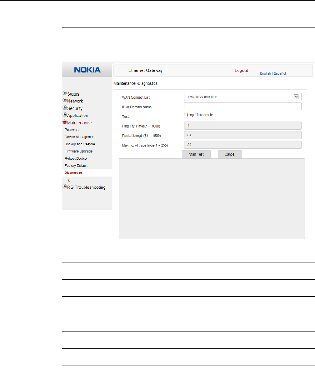
Configure a A-020W-A
96
7368 ISAM CPE A-020W-A Product Guide
3FE-47511-AAAA-TCZZA Issue: 01
Procedure 41 Diagnose connections
1Select Maintenance > Diagnostics from the top-level menu in the Ethernet Gateway window,
as shown in Figure 46.
Figure 46 Diagnostics window
2Choose a WAN connection to diagnose from the drop-down menu.
3Enter the IP address or domain name.
4Select the test type: ping, traceroute, or both.
5Enter the number of ping attempts to perform (1 to 1000); the default is 4.
6Enter a ping packet length (64 to 1500); the default is 64.
7Enter the maximum number of trace hops (1 to 255); the default is 30.
8Click Start Test. Results will be displayed at the bottom of the window.
Release 05.08.01 | June 2018 | Edition 01
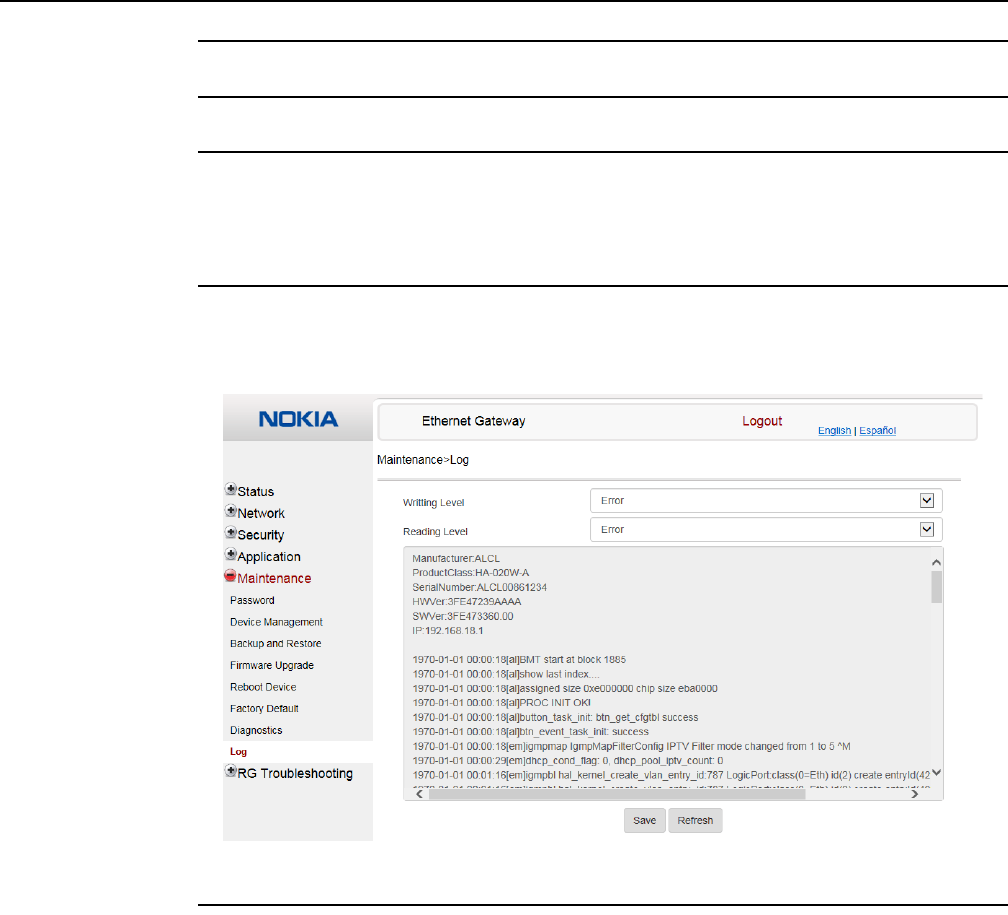
7368 ISAM CPE A-020W-A Product Guide Configure a A-020W-A
Issue: 01 3FE-47511-AAAA-TCZZA 97
9Click Cancel to cancel the test.
10 STOP. This procedure is complete.
Procedure 42 View log files
1Select Maintenance > Log from the top-level menu in the Ethernet Gateway window, as
shown in Figure 47.
Figure 47 Log window
2Choose a write level from the drop-down menu to determine which types of events are
recorded in the log file:
•Emergency
•Alert
•Critical
•Error
•Warning
•Notice
•Informational
•Debug
Release 05.08.01 | June 2018 | Edition 01

Configure a A-020W-A
98
7368 ISAM CPE A-020W-A Product Guide
3FE-47511-AAAA-TCZZA Issue: 01
3Choose a reading level from the drop-down menu to determine which types of events to
display from the log file:
•Emergency
•Alert
•Critical
•Error
•Warning
•Notice
•Informational
•Debug
4The log file is displayed at the bottom of the window.
5STOP. This procedure is complete.
8.1.7 RG troubleshooting counters
The Troubleshooting Counters feature enables service providers and end users to
monitor the performance of their broadband connection.
Tests are run to retrieve upstream and downstream throughput, latency, and DNS
response time. The Troubleshooting Counters window also displays upstream and
downstream packet loss and Internet status.
Procedure 43 Retrieve Residential Gateway (RG) troubleshooting counters
1Select RG Troubleshooting Counters from the left menu in the Ethernet Gateway window.
The RG Troubleshooting Counters window appears; see Figure 48.
Release 05.08.01 | June 2018 | Edition 01
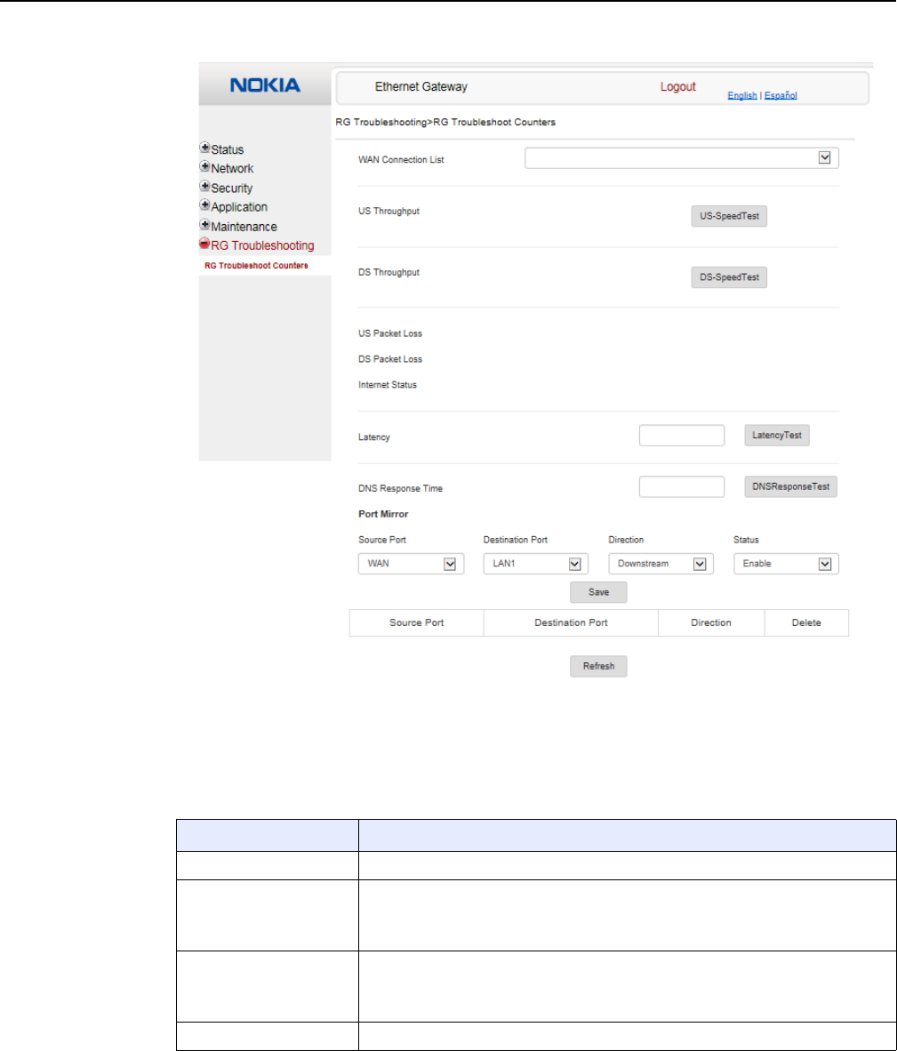
7368 ISAM CPE A-020W-A Product Guide Configure a A-020W-A
Issue: 01 3FE-47511-AAAA-TCZZA 99
Figure 48 RG Troubleshooting Counters window
Table 38 describes the fields in the RG Troubleshooting Counters window.
Table 38 RG Troubleshooting Counters parameters
Field Description
WAN Connection List Select a WAN connection from the list
US Throughput This test is used to determine the upstream throughput/speed
Click US Speed Test to specify the time for the upstream test
The default is weekly, performed at idle to a public server
DS Throughput This test is used to determine the downstream throughput/speed
Click DS Speed Test to specify the time for the downstream test
The default is weekly, performed at idle to a public server
US Packet Loss The number of upstream packages lost
(1 of 2)
Release 05.08.01 | June 2018 | Edition 01
Configure a A-020W-A
100
7368 ISAM CPE A-020W-A Product Guide
3FE-47511-AAAA-TCZZA Issue: 01
2Configure the test times if desired.
3Click Refresh to update the data.
4STOP. This procedure is complete.
DS Packet Loss The number of downstream packages lost
Internet Status Whether the broadband connections is active (UP) or not (DOWN)
Latency This test is used to determine the lowest round-trip time in milliseconds by pinging
the target server multiple times
Click Latency Test to specify the time for the test
The default is weekly, performed at idle to a public server
DNS Response Time This test is used to determine the lowest round-trip time in milliseconds by sending
a request to the target DNS server
Click DNS Response Test to specify the time for the test
The default is weekly, performed at idle to a public server
Port Mirror Select Source Port, Destination Port, Direction (Up or Down) and Status (Enable or
Disable)
Field Description
(2 of 2)
Release 05.08.01 | June 2018 | Edition 01

Copyright 2018 Nokia.
3FE-47511-AAAA-TCZZA
Release 05.08.01 | June 2018 | Edition 01