Nokia Bell G240WF G-240W-F User Manual 7368 ISAM ONT G 240W F Product Guide
Alcatel-Lucent Shanghai Bell Co. Ltd. G-240W-F 7368 ISAM ONT G 240W F Product Guide
User Guide

Nokia — Proprietary and confidential
Use pursuant to applicable agreements
7368 Intelligent Services Access
Manager ONT
7368 ISAM ONT G-240W-F Product
Guide
Edition 01
Issue: 01
7368 ISAM ONT G-240W-F Product Guide
DRAFT

2
7368 ISAM ONT G-240W-F Product Guide
Edition 01 Issue: 01
Nokia is a registered trademark of Nokia Corporation. Other products and company
names mentioned herein may be trademarks or tradenames of their respective
owners.
The information presented is subject to change without notice. No responsibility is
assumed for inaccuracies contained herein.
© 2017 Nokia.
Contains proprietary/trade secret information which is the property of Nokia and must
not be made available to, or copied or used by anyone outside Nokia without its
written authorization. Not to be used or disclosed except in accordance with
applicable agreements.
DRAFT

7368 ISAM ONT G-240W-F Product Guide Preface
Issue: 01 Edition 01 3
1Preface
This preface provides general information about the documentation set for optical
network terminals (ONTs).
1.1 Scope
This documentation set provides information about safety, features and functionality,
ordering, hardware installation and maintenance, and software installation
procedures for the current release.
1.2 Audience
This documentation set is intended for planners, administrators, operators, and
maintenance personnel involved in installing, upgrading, or maintaining the ONTs.
1.3 Required knowledge
The reader must be familiar with general telecommunications principles.
1.4 Acronyms and initialisms
The expansions and optional descriptions of most acronyms and initialisms appear
in the glossary.
1.5 Assistance and ordering phone numbers
Nokia provides global technical support through regional call centers. Phone
numbers for the regional call centers are available at the following URL:
http://support.alcatel-lucent.com.
For ordering information, contact your Nokia sales representative.
DRAFT

Preface
4
7368 ISAM ONT G-240W-F Product Guide
Edition 01 Issue: 01
1.6 Nokia quality processes
Nokia’s ONT quality practices are in compliance with TL 9000 requirements. These
requirements are documented in the Fixed Networks Quality Manual
3FQ-30146-6000-QRZZA. The quality practices adequately ensure that technical
requirements and customer end-point requirements are met. The customer or its
representatives may be allowed to perform on-site quality surveillance audits, as
agreed upon during contract negotiations
1.7 Safety information
For safety information, see the appropriate safety guidelines chapter.
1.8 Documents
Documents are available using ALED or OLCS.
Procedure 1 To download a ZIP file package of the customer documentation
1Navigate to http://support.alcatel-lucent.com and enter your user name and password. If you
are a new user and require access to this service, please contact your Nokia sales
representative.
2From the Technical Content for drop-down menu, choose the product.
3Click on Downloads: Electronic Delivery.
4Choose Documentation from the drop-down menu and click Next.
5Select the image from the drop-down menu and click Next.
6Follow the on-screen directions to download the file.
DRAFT
7368 ISAM ONT G-240W-F Product Guide Preface
Issue: 01 Edition 01 5
Procedure 2 To access individual documents
Individual PDFs of customer documents are also accessible through the Nokia Customer Support
website.
1Navigate to http://support.alcatel-lucent.com and enter your user name and password. If you
are a new user and require access to this service, please contact your Nokia sales
representative.
2From the Technical Content for drop-down menu, choose the product.
3Click on Manuals and Guides to display a list of customer documents by title and part
number. You can filter this list using the Release drop-down menu.
4Click on the PDF to open or save the file.
1.9 Special information
The following are examples of how special information is presented in this document.
Danger — Danger indicates that the described activity or
situation may result in serious personal injury or death; for
example, high voltage or electric shock hazards.
Warning — Warning indicates that the described activity or
situation may, or will, cause equipment damage or serious
performance problems.
Caution — Caution indicates that the described activity or
situation may, or will, cause service interruption.
Note — A note provides information that is, or may be, of
special interest.
DRAFT

Preface
6
7368 ISAM ONT G-240W-F Product Guide
Edition 01 Issue: 01
1.9.1 Procedures with options or substeps
When there are options in a procedure, they are identified by letters. When there are
required substeps in a procedure, they are identified by roman numerals.
Procedure 3 Example of options in a procedure
At step 1, you can choose option a or b. At step 2, you must do what the step indicates.
1This step offers two options. You must choose one of the following:
aThis is one option.
bThis is another option.
2You must perform this step.
Procedure 4 Example of required substeps in a procedure
At step 1, you must perform a series of substeps within a step. At step 2, you must do what the
step indicates.
1This step has a series of substeps that you must perform to complete the step. You must
perform the following substeps:
iThis is the first substep.
ii This is the second substep.
iii This is the third substep.
2 You must perform this step.
DRAFT

7368 ISAM ONT G-240W-F Product Guide Preface
Issue: 01 Edition 01 7
1.10 Multiple PDF document search
You can use Adobe Reader Release 6.0 and later to search multiple PDF files for a
common term. Adobe Reader displays the results in a single display panel. The
results are grouped by PDF file, and you can expand the entry for each file.
Procedure 5 To search multiple PDF files for a common term
1Open Adobe Acrobat Reader.
2Choose Edit→Search from the Acrobat Reader main menu. The Search PDF panel appears.
3Enter the search criteria.
4Click on the All PDF Documents In radio button.
5Select the folder in which to search using the drop-down menu.
6Click on the Search button.
Acrobat Reader displays the search results. You can expand the entries for each document
by clicking on the + symbol.
Note — The PDF files in which you search must be in the same
folder.
DRAFT

Preface
8
7368 ISAM ONT G-240W-F Product Guide
Edition 01 Issue: 01
DRAFT

7368 ISAM ONT G-240W-F Product Guide
Issue: 01 Edition 01 9
Table of contents
1 Preface.............................................................................................3
1.1 Scope ..........................................................................................................3
1.2 Audience......................................................................................................3
1.3 Required knowledge....................................................................................3
1.4 Acronyms and initialisms .............................................................................3
1.5 Assistance and ordering phone numbers ....................................................3
1.6 Nokia quality processes...............................................................................4
1.7 Safety information........................................................................................4
1.8 Documents ..................................................................................................4
1.9 Special information ......................................................................................5
1.9.1 Procedures with options or substeps...........................................................6
1.10 Multiple PDF document search ...................................................................7
2 ETSI ONT safety guidelines .........................................................17
2.1 Safety instructions .....................................................................................17
2.1.1 Safety instruction boxes ............................................................................17
2.1.2 Safety-related labels..................................................................................18
2.2 Safety standards compliance ....................................................................19
2.2.1 EMC, EMI, and ESD compliance...............................................................19
2.2.2 Equipment safety standard compliance.....................................................19
2.2.3 Environmental standard compliance .........................................................20
2.2.4 Laser product standard compliance ..........................................................20
2.2.5 Resistibility requirements compliance .......................................................20
2.2.6 Acoustic noise emission standard compliance..........................................20
2.3 Electrical safety guidelines ........................................................................20
2.3.1 Power supplies ..........................................................................................21
2.3.2 Cabling ......................................................................................................21
2.3.3 Protective earth .........................................................................................21
2.4 ESD safety guidelines ...............................................................................21
2.5 Laser safety guidelines..............................................................................21
2.5.1 Laser classification ....................................................................................22
2.5.1.1 Laser warning labels..................................................................................22
2.5.2 Transmit optical output ..............................................................................24
2.5.3 Normal laser operation ..............................................................................24
2.5.4 Location class............................................................................................25
2.6 Environmental requirements......................................................................25
3 ETSI environmental and CRoHS guidelines...............................27
3.1 Environmental labels .................................................................................27
3.1.1 Overview....................................................................................................27
3.1.2 Environmental related labels .....................................................................27
3.1.2.1 Products below Maximum Concentration Value (MCV) label....................27
3.1.2.2 Products containing hazardous substances above Maximum
Concentration Value (MCV) label ..............................................................28
3.2 Hazardous Substances Table (HST).........................................................29
3.3 Other environmental requirements ............................................................30
DRAFT

10
7368 ISAM ONT G-240W-F Product Guide
Edition 01 Issue: 01
3.3.1 ONT environmental requirements .............................................................30
3.3.2 Storage ......................................................................................................30
3.3.3 Transportation ...........................................................................................30
3.3.4 Stationary use............................................................................................30
3.3.5 Thermal limitations ....................................................................................30
3.3.6 Material content compliance......................................................................31
3.3.7 End-of-life collection and treatment ...........................................................31
4 ANSI ONT safety guidelines ........................................................33
4.1 Safety instructions .....................................................................................33
4.1.1 Safety instruction boxes in customer documentation ................................33
4.1.2 Safety-related labels..................................................................................34
4.2 Safety standards compliance ....................................................................35
4.2.1 EMC, EMI, and ESD standards compliance..............................................36
4.2.2 Equipment safety standard compliance.....................................................36
4.2.3 Environmental standards compliance........................................................37
4.2.4 Laser product standards compliance.........................................................37
4.2.5 Resistibility requirements compliance .......................................................38
4.3 Laser safety guidelines..............................................................................38
4.3.1 Laser warning labels..................................................................................38
4.3.2 Laser classification ....................................................................................40
4.3.3 Transmit optical output ..............................................................................41
4.3.4 Normal laser operation ..............................................................................41
4.3.5 Location class............................................................................................41
4.4 Electrical safety guidelines ........................................................................42
4.4.1 Power supplies ..........................................................................................42
4.4.2 Cabling ......................................................................................................42
4.4.3 Protective earth .........................................................................................42
4.5 ESD safety guidelines ...............................................................................42
4.6 Environmental requirements......................................................................43
5 G-240W-F unit data sheet.............................................................45
5.1 G-240W-F part numbers and identification................................................46
5.2 G-240W-F general description ..................................................................47
5.2.1 TR-069 support..........................................................................................48
5.2.2 TR-104 parameter extension support for voice service.............................49
5.2.3 TR-181 Wi-Fi objects adapted in TR-098 ..................................................49
5.2.4 Mobile offload support ...............................................................................49
5.2.5 Bridged Residential Gateway (BRG) support ............................................50
5.2.6 Support for soft GRE tunnels.....................................................................50
5.2.6.1 GRE...........................................................................................................51
5.2.6.2 Soft GRE ...................................................................................................51
5.3 G-240W-F software and installation feature support .................................52
5.4 G-240W-F interfaces and interface capacity .............................................53
5.4.1 G-240W-F connections and components ..................................................53
5.5 G-240W-F LEDs ........................................................................................55
5.6 G-240W-F detailed specifications..............................................................57
5.7 G-240W-F GEM ports and T-CONTs ........................................................58
5.8 G-240W-F performance monitoring statistics ............................................58
5.9 G-240W-F functional blocks ......................................................................60
DRAFT

7368 ISAM ONT G-240W-F Product Guide
Issue: 01 Edition 01 11
5.10 G-240W-F standards compliance..............................................................62
5.10.1 Energy-related products standby and off modes compliance....................63
5.11 G-240W-F special considerations .............................................................63
5.11.1 Wi-Fi service..............................................................................................63
5.11.1.1 Wi-Fi physical features ..............................................................................64
5.11.1.2 Wi-Fi standards and certifications .............................................................64
5.11.1.3 Wi-Fi GUI features.....................................................................................64
5.11.2 G-240W-F ONT considerations and limitations .........................................64
6 Install a G-240W-F indoor ONT....................................................67
6.1 Purpose .....................................................................................................67
6.2 General......................................................................................................67
6.3 Prerequisites..............................................................................................67
6.4 Recommended tools..................................................................................67
6.5 Safety information......................................................................................68
6.6 Procedure ..................................................................................................69
7 Replace a G-240W-F indoor ONT ................................................75
7.1 Purpose .....................................................................................................75
7.2 General......................................................................................................75
7.3 Prerequisites..............................................................................................75
7.4 Recommended tools..................................................................................75
7.5 Safety information......................................................................................76
7.6 Procedure ..................................................................................................77
8 Configure a G-240W-F indoor ONT .............................................83
8.1 General......................................................................................................83
8.2 HGU mode GUI configuration....................................................................83
8.2.1 Login..........................................................................................................83
8.2.2 Device and connection status....................................................................84
8.2.3 Network configuration................................................................................94
8.2.4 Security configuration ..............................................................................115
8.2.5 Application configuration .........................................................................124
8.2.6 Maintenance ............................................................................................131
8.2.7 RG troubleshooting counters...................................................................143
8.3 SFU mode GUI configuration ..................................................................145
8.3.1 Login........................................................................................................145
8.3.2 Device and connection status..................................................................146
8.3.3 Maintenance ............................................................................................148
8.4 Operator ID..............................................................................................150
9 ONT configuration file over OMCI .............................................153
9.1 Purpose ...................................................................................................153
9.2 Supported configuration file types ...........................................................153
9.2.1 Filename conventions..............................................................................155
9.3 ONT configuration file over OMCI ...........................................................155
DRAFT

12
7368 ISAM ONT G-240W-F Product Guide
Edition 01 Issue: 01
DRAFT

7368 ISAM ONT G-240W-F Product Guide
Issue: 01 Edition 01 13
List of figures
2 ETSI ONT safety guidelines .........................................................17
Figure 1 PSE certification ........................................................................................19
Figure 2 Laser product label ....................................................................................22
Figure 3 Laser classification label............................................................................23
Figure 4 Laser warning labels..................................................................................24
3 ETSI environmental and CRoHS guidelines...............................27
Figure 5 Products below MCV value label...............................................................28
Figure 6 Products above MCV value label ..............................................................29
Figure 7 Recycling/take back/disposal of product symbol .......................................31
4 ANSI ONT safety guidelines ........................................................33
Figure 8 Sample safety label on the ONT equipment..............................................35
Figure 9 Sample laser product label showing CDRH 21 CFR compliance..............37
Figure 10 Laser product label ....................................................................................39
Figure 11 Laser classification label............................................................................39
Figure 12 Laser warning labels..................................................................................40
Figure 13 Sample laser product safety label on the ONT equipment ........................41
5 G-240W-F unit data sheet.............................................................45
Figure 14 SoftGRE-based architecture......................................................................52
Figure 15 G-240W-F indoor ONT physical connections (back view).........................54
Figure 16 G-240W-F ONT Reset, LED, WLAN, and WPS buttons and fiber
optic connection (bottom and side view) ...................................................54
Figure 17 G-240W-F indoor ONT LEDs ....................................................................56
Figure 18 Single-residence Wi-Fi ONT with Gigabit Ethernet and POTS and
without RF video........................................................................................61
Figure 19 G-240W-F ONT hardware block................................................................61
6 Install a G-240W-F indoor ONT....................................................67
Figure 20 G-240W-F indoor ONT wall mounting holes (bottom view) .......................69
Figure 21 G-240W-F indoor ONT connections (back view).......................................70
Figure 22 G-240W-F ONT Reset, LED, WLAN, and WPS buttons and fiber
optic connection (bottom and side view) ...................................................71
Figure 23 G-240W-F indoor ONT with fiber cover open ............................................72
7 Replace a G-240W-F indoor ONT ................................................75
Figure 24 G-240W-F indoor ONT Reset, LED, WLAN, and WPS buttons
(side)..........................................................................................................77
Figure 25 G-240W-F indoor ONT connections (back view).......................................78
Figure 26 G-240W-F indoor ONT fiber optic port (bottom view)................................79
8 Configure a G-240W-F indoor ONT .............................................83
Figure 27 Web login window......................................................................................84
Figure 28 Device Information window........................................................................85
Figure 29 LAN status window ....................................................................................86
Figure 30 WAN status window...................................................................................88
Figure 31 WAN status IPv6 window ..........................................................................89
DRAFT

14
7368 ISAM ONT G-240W-F Product Guide
Edition 01 Issue: 01
Figure 32 Home networking information window.......................................................90
Figure 33 Optics module status window ....................................................................91
Figure 34 Voice Information window..........................................................................93
Figure 35 LAN network window .................................................................................95
Figure 36 LAN IPv6 network window.........................................................................97
Figure 37 WAN network window................................................................................98
Figure 38 WiFi network window...............................................................................100
Figure 39 Wireless Schedule window......................................................................102
Figure 40 Routing network window..........................................................................103
Figure 41 DNS network window ..............................................................................105
Figure 42 TR-069 network window..........................................................................106
Figure 43 GRE Tunnel window................................................................................107
Figure 44 QoS Config window (L2)..........................................................................109
Figure 45 QoS Config window (L3)..........................................................................110
Figure 46 US Classifier Policy window ....................................................................112
Figure 47 US Classifier window...............................................................................113
Figure 48 US Classifier Rules window.....................................................................114
Figure 49 Firewall window .......................................................................................116
Figure 50 MAC filter window....................................................................................117
Figure 51 IP filter window ........................................................................................118
Figure 52 URL Filter window ...................................................................................119
Figure 53 Parental Control window..........................................................................120
Figure 54 DMZ and ALG window.............................................................................122
Figure 55 Access Control window ...........................................................................123
Figure 56 Port forwarding window ...........................................................................125
Figure 57 Port Triggering window............................................................................126
Figure 58 DDNS window .........................................................................................127
Figure 59 NTP window ............................................................................................128
Figure 60 USB storage window ...............................................................................129
Figure 61 UPnP and DLNA window.........................................................................130
Figure 62 Password window....................................................................................132
Figure 63 LOID Config window................................................................................133
Figure 64 SLID configuration window......................................................................134
Figure 65 Device management window...................................................................135
Figure 66 Backup and Restore window ...................................................................136
Figure 67 Firmware upgrade window ......................................................................137
Figure 68 Reboot window ........................................................................................138
Figure 69 Factory default window............................................................................139
Figure 70 Diagnose window ....................................................................................140
Figure 71 Log window..............................................................................................141
Figure 72 PPPoE Diagnostics window ....................................................................142
Figure 73 PPPoE diagnostics results ......................................................................143
Figure 74 RG Troubleshooting Counters window....................................................144
Figure 75 Web login window....................................................................................146
Figure 76 Device Information window......................................................................147
Figure 77 Password window....................................................................................148
Figure 78 LOID configuration window......................................................................149
Figure 79 SLID configuration window......................................................................150
DRAFT

7368 ISAM ONT G-240W-F Product Guide
Issue: 01 Edition 01 15
List of tables
2 ETSI ONT safety guidelines .........................................................17
Table 1 Safety labels ..............................................................................................18
4 ANSI ONT safety guidelines ........................................................33
Table 2 Safety labels ..............................................................................................34
5 G-240W-F unit data sheet.............................................................45
Table 3 Identification of G-240W-F indoor ONTs ...................................................46
Table 4 G-240W-F indoor ONT interface connection capacity...............................53
Table 5 G-240W-F indoor ONT physical connections ............................................55
Table 6 G-240W-F indoor ONT LEDs ....................................................................56
Table 7 G-240W-F indoor ONT physical specifications..........................................57
Table 8 G-240W-F indoor ONT power consumption specifications .......................57
Table 9 G-240W-F indoor ONT environmental specifications ................................58
Table 10 G-240W-F indoor ONT capacity for GEM ports and T-CONTs .................58
Table 11 Package P ONTs ONTENET performance monitoring statistics...............59
Table 12 Package P ONTs ONTL2UNI performance monitoring statistics ..............59
Table 13 Package P ONTs PONONTTC, PONONTMCTC, PONONTTCHSI,
PONONTTCCES, PONONTTCFLOW, PONONTTCVOIP
performance monitoring statistics..............................................................59
Table 14 Package P ONTs PONONTTC aggregate performance monitoring
statistics.....................................................................................................60
Table 15 G-240W-F ONT considerations and limitations .........................................64
8 Configure a G-240W-F indoor ONT .............................................83
Table 16 Device Information parameters .................................................................85
Table 17 LAN status parameters..............................................................................86
Table 18 WAN status parameters ............................................................................88
Table 19 WAN status IPv6 parameters ....................................................................89
Table 20 Home networking parameters ...................................................................91
Table 21 Optics module status parameters..............................................................92
Table 22 Voice Information parameters ...................................................................93
Table 23 LAN network parameters...........................................................................95
Table 24 LAN IPv6 network parameters...................................................................97
Table 25 WAN network parameters .........................................................................99
Table 26 WiFi network parameters.........................................................................100
Table 27 Routing network parameters ...................................................................104
Table 28 DNS network parameters ........................................................................105
Table 29 TR-069 network parameters....................................................................106
Table 30 GRE Tunnel parameters..........................................................................107
Table 31 QoS Config parameters...........................................................................111
Table 32 US Classifier Policy parameters ..............................................................112
Table 33 US Classifier parameters.........................................................................113
Table 34 US Classifier Rules parameters ..............................................................114
Table 35 Firewall parameters .................................................................................116
Table 36 MAC filter parameters..............................................................................117
Table 37 IP filter parameters ..................................................................................118
DRAFT

16
7368 ISAM ONT G-240W-F Product Guide
Edition 01 Issue: 01
Table 38 URL Filter parameters .............................................................................120
Table 39 Parental control parameters ....................................................................121
Table 40 DMZ and ALG parameters ......................................................................122
Table 41 Access control parameters ......................................................................123
Table 42 Port forwarding parameters .....................................................................125
Table 43 Port triggering parameters.......................................................................126
Table 44 DDNS parameters ...................................................................................128
Table 45 NTP parameters ......................................................................................129
Table 46 USB storage parameters .........................................................................130
Table 47 Password parameters..............................................................................132
Table 48 LOID configuration parameters ...............................................................133
Table 49 SLID configuration parameters................................................................134
Table 50 Device management parameters ............................................................135
Table 51 PPPoE diagnostics results parameters ...................................................143
Table 52 RG Troubleshooting Counters parameters..............................................144
Table 53 Device Information parameters ...............................................................147
Table 54 Password parameters..............................................................................148
Table 55 SLID configuration parameters................................................................150
9 ONT configuration file over OMCI .............................................153
Table 56 Supported configuration files ...................................................................154
DRAFT
7368 ISAM ONT G-240W-F Product Guide ETSI ONT safety guidelines
Issue: 01 Edition 01 17
2 ETSI ONT safety guidelines
This chapter provides information about the mandatory regulations that govern the
installation and operation of the optical network terminals (ONTs).
2.1 Safety instructions
This section describes the safety instructions that are provided in the ONT customer
documentation and on the equipment.
2.1.1 Safety instruction boxes
The safety instruction boxes are provided in the ONT customer documentation.
Observe the instructions to meet safety requirements.
The following is an example of the Danger box.
The Danger box indicates that the described activity or situation may pose a threat
to personal safety. It calls attention to a situation or procedure which, if not correctly
performed or adhered to, may result in death or serious physical harm.
Do not proceed beyond a Danger box until the indicated conditions are fully
understood and met.
The following is an example of the Warning box.
The Warning box indicates that the described activity or situation may, or will, cause
equipment damage, loss of data, or serious performance problems. It identifies a
possible equipment-damaging situation or provides essential information to avoid the
degradation of system operations or data.
Do not proceed beyond a warning until the indicated conditions are fully understood
and met.
Danger — Possibility of personal injury.
Warning 1 — Possibility of equipment damage.
Warning 2 — Possibility of data loss.
DRAFT
ETSI ONT safety guidelines
18
7368 ISAM ONT G-240W-F Product Guide
Edition 01 Issue: 01
The following is an example of the Caution box.
The Caution box indicates that the described activity or situation may, or will, cause
service interruption.
Do not proceed beyond a caution until the indicated conditions are fully understood
and met.
The following is an example of the Note box.
The Note box provides information that assists the personnel working with ONTs. It
does not provide safety-related instructions.
2.1.2 Safety-related labels
The ONT equipment is labeled with the specific safety instructions and compliance
information that is related to a variant of the ONT. Observe the instructions on the
safety labels.
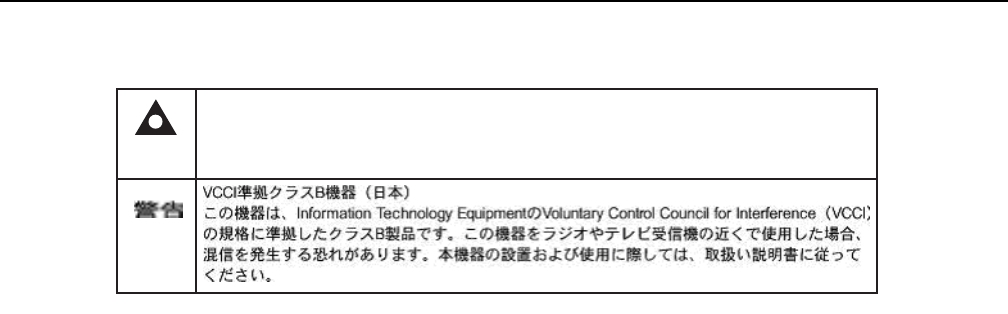
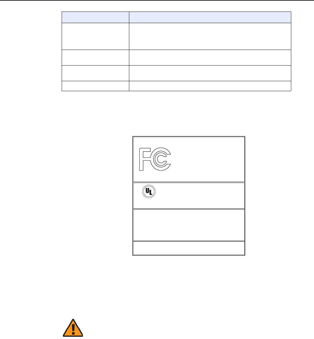
Table 1 provides sample safety labels on the ONT equipment.
Table 1 Safety labels
Figure 1 shows the PSE certification.
Caution 1 — Possibility of service interruption.
Caution 2 — Service interruption.
Note — Information of special interest.
Description Label text
ESD warning Caution: This assembly contains an electrostatic sensitive device.
Laser classification Class 1 laser product
PSE marking These power supplies are Japan PSE certified and compliant with
Japan VCCI emissions standards.
DRAFT
7368 ISAM ONT G-240W-F Product Guide ETSI ONT safety guidelines
Issue: 01 Edition 01 19
Figure 1 PSE certification
2.2 Safety standards compliance
This section describes the ONT compliance with the European safety standards.
2.2.1 EMC, EMI, and ESD compliance
The ONT equipment complies with the following EMC, EMI, and ESD requirements:
•EN 300-328 v1.9.1 wide band data transmission standards for 2.4GHz bands
•EN 300-386 V1.5.1: Electromagnetic Compatibility and Radio Spectrum Matters
(ERM): Telecommunications Network Equipment; Electromagnetic Compatibility
(EMC) requirements; Electrostatic Discharge (ESD) requirements
•EN 55022 (2006): Class B, Information Technology Equipment, Radio
Disturbance Characteristics, limits and methods of measurement
•EN 55024 (2010): Information Technology Equipment, Immunity Characteristics,
limits and methods of measurement
•European Council Directive 2004/108/EC
•EN 300-386 V1.4.1: 2008
•EN 55022:2006 Class B (ONTs)
2.2.2 Equipment safety standard compliance
The ONT equipment complies with the requirements of EN 60950-1, Safety of
Information Technology Equipment for use in a restricted location (per R-269).
This is a Class B product based on the standard of the Voluntary Control Council for Interference
from Information Technology Equipment (VCCI). If this is used near a radio or television receiver in
a domestic environment, it may cause radio interference. Install and use the equipment according
to the instruction manual.
Warning
19841
DRAFT

ETSI ONT safety guidelines
20
7368 ISAM ONT G-240W-F Product Guide
Edition 01 Issue: 01
2.2.3 Environmental standard compliance
The ONT equipment complies with the EN 300 019 European environmental
standards.
2.2.4 Laser product standard compliance
For most ONTs, the ONT equipment complies with EN 60825-1 and IEC 60825-2 for
laser products. If there is an exception to this compliance regulation, you can find this
information in the standards compliance section of the unit data sheet in this Product
Guide.
2.2.5 Resistibility requirements compliance
The ONT equipment complies with the requirements of ITU Recommendation K.21
for resistibility of telecommunication equipment installed in customer premises to
over voltage and overcurrents.
2.2.6 Acoustic noise emission standard compliance
The ONT equipment complies with EN 300 753 acoustic noise emission limit and test
methods.
2.3 Electrical safety guidelines
This section provides the electrical safety guidelines for the ONT equipment.
Note 1 — The ONTs comply with the U.S. National Electrical
Code. However, local electrical authorities have jurisdiction
when there are differences between the local and U.S.
standards.
Note 2 — The ONTs comply with BS EN 61140.
DRAFT

7368 ISAM ONT G-240W-F Product Guide ETSI ONT safety guidelines
Issue: 01 Edition 01 21
2.3.1 Power supplies
The use of any non-Nokia approved power supplies or power adapters is not
supported or endorsed by Nokia. Such use will void any warranty or support contract
with Nokia. Such use greatly increases the danger of damage to equipment or
property.
2.3.2 Cabling
The following are the guidelines regarding cables used for the ONT equipment:
•All cables must be approved by the relevant national electrical code.
•The cables for outdoor installation of ONTs must be suitable for outdoor use.
• POTS wiring run outside the subscriber premises must comply with the
requirements of local electrical codes. In some markets, the maximum allowed
length of the outside run is 140 feet (43 m). If the outside run is longer, NEC
requires primary protection at both the exit and entry points for the wire.
2.3.3 Protective earth
Earthing and bonding of the ONTs must comply with the requirements of local
electrical codes.
2.4 ESD safety guidelines
The ONT equipment is sensitive to ESD. Operations personnel must observe the
following ESD instructions when they handle the ONT equipment.
During installation and maintenance, service personnel must wear wrist straps to
prevent damage caused by ESD.
2.5 Laser safety guidelines
Observe the following instructions when you perform installation, operations, and
maintenance tasks on the ONT equipment.
Caution — This equipment is ESD sensitive. Proper ESD
protections should be used when you enter the TELCO Access
portion of the ONT.
DRAFT
ETSI ONT safety guidelines
22
7368 ISAM ONT G-240W-F Product Guide
Edition 01 Issue: 01
Only qualified service personnel who are extremely familiar with laser radiation
hazards should install or remove the fiber optic cables and units in this system.
Observe the following danger for laser hazard. Eyes can be damaged when they are
exposed to a laser beam. Take necessary precautions before you plug in the optical
modules.
2.5.1 Laser classification
The ONT is classified as a Class 1 laser product based on its transmit optical output.
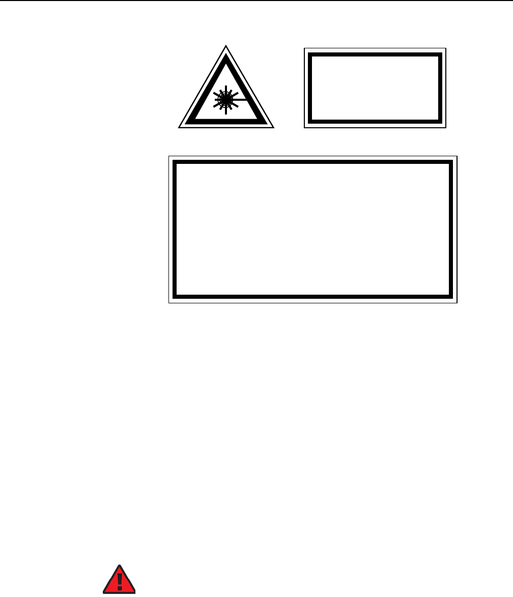
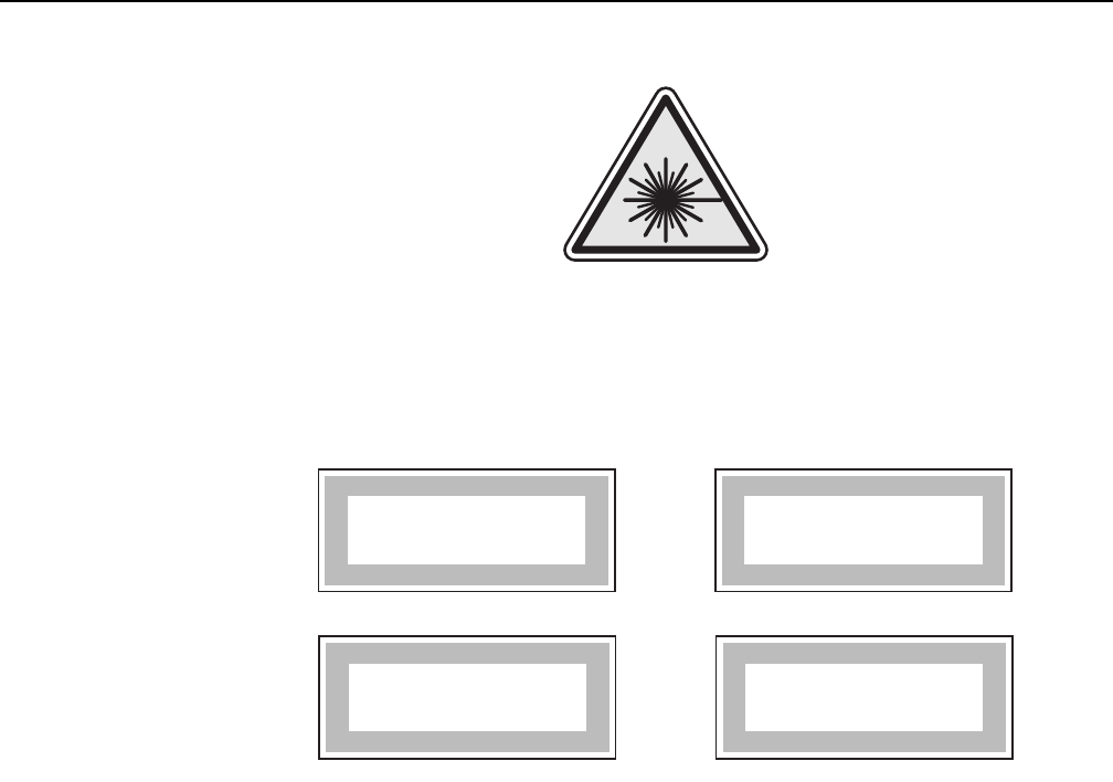
2.5.1.1 Laser warning labels
The following figures show the labels related to laser product, classification and
warning.
Figure 2 shows a laser product label.
Figure 2 Laser product label
Figure 3 shows a laser classification label. Laser classification labels may be
provided in other languages.
Danger — There may be invisible laser radiation at the fiber
optic cable when the cable is removed from the connector.
Avoid direct exposure to the laser beam.
Danger — Possibility of equipment damage. Risk of eye
damage by laser radiation.
18455
DRAFT

7368 ISAM ONT G-240W-F Product Guide ETSI ONT safety guidelines
Issue: 01 Edition 01 23
Figure 3 Laser classification label
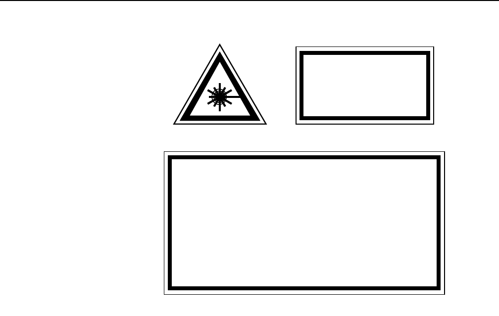
Figure 4 shows a laser warning label and an explanatory label for laser products.
Labels and warning may be provided in other languages. The explanatory label
provides the following information:
•a warning that calls attention to the invisible laser radiation
•an instruction against staring into the beam or viewing directly with optical
instruments
•wavelength
•normal output power
•maximum output power
LASER CLASSE 1CLASE 1 DEL LASER
CLASS 1 LASER PRODUCT PRODUCTO LASER CLASE 1
18992
'
'
DRAFT
ETSI ONT safety guidelines
24
7368 ISAM ONT G-240W-F Product Guide
Edition 01 Issue: 01
Figure 4 Laser warning labels
2.5.2 Transmit optical output
The maximum transmit optical output of an ONT is +5 dBm.
2.5.3 Normal laser operation
In normal operation, fiber cable laser radiation is always off until it receives signal
from the line terminal card.
Eyes can be damaged when they exposed to a laser beam. Operating personnel
must observe the instructions on the laser explanatory label before plugging in the
optical module.
INVISIBLE LASER RADIATION
DO NOT STARE INTO BEAM
OR VIEW DIRECTLY WITH
OPTICAL INSTRUMENTS
Wavelength(s): xxxx nm
Normal output power: xx m W
Max output power: yyy m W
Laser Warning Label Laser Warning Label
CLASS 1 LASER PRODUCT
INVISIBLE LASER RADIATION PRESENT AT FIBER OPTIC CABLE
WHEN NOT CONNECTED. AVOID DIRECT EXPOSURE TO BEAM.
RAYONNEMENT LASER CLASSE 1
RAYONNEMENT LASER INVISIBLE
EVITER TOUTE EXPOSITION AU FAISCEAU
NE PAS DEMONTER. FAIRE APPEL A UN PERSONNELL QUALIFIE
CLASE 1 DEL LASER
RADIACION DE LASER INVISIBLE. EVITAR CUALOUIER EXPOSICION AL
RAYO LASER. NO DESMONTAR. LLAMAR A PERSONAL AUTORIZADO
Laser Warning Label
18993
'
Danger — Risk of eye damage by laser radiation.
DRAFT

7368 ISAM ONT G-240W-F Product Guide ETSI ONT safety guidelines
Issue: 01 Edition 01 25
2.5.4 Location class
Use cable supports and guides to protect the receptacles from strain.
2.6 Environmental requirements
See the ONT technical specification documentation for more information about
temperature ranges.
During operation in the supported temperature range, condensation inside the ONT
caused by humidity is not an issue. To avoid condensation caused by rapid changes
in temperature and humidity, Nokia recommends:
•The door of the ONT not be opened until temperature inside and outside the
enclosure has stabilized.
•If the door of the ONT must be opened after a rapid change in temperature or
humidity, use a dry cloth to wipe down the metal interior to prevent the risk of
condensation.
•When high humidity is present, installation of a cover or tent over the ONT helps
prevent condensation when the door is opened.
DRAFT

ETSI ONT safety guidelines
26
7368 ISAM ONT G-240W-F Product Guide
Edition 01 Issue: 01
DRAFT

7368 ISAM ONT G-240W-F Product Guide ETSI environmental and CRoHS guidelines
Issue: 01 Edition 01 27
3 ETSI environmental and CRoHS
guidelines
This chapter provides information about the ETSI environmental China Restriction of
Hazardous Substances (CRoHS) regulations that govern the installation and
operation of the optical line termination (OLT) and optical network termination (ONT)
systems. This chapter also includes environmental operation parameters of general
interest.
3.1 Environmental labels
This section describes the environmental instructions that are provided with the
customer documentation, equipment, and location where the equipment resides.
3.1.1 Overview
CRoHS is applicable to Electronic Information Products (EIP) manufactured or sold
and imported in the territory of the mainland of the People’s Republic of China. EIP
refers to products and their accessories manufactured by using electronic
information technology, including electronic communications products and such
subcomponents as batteries and cables.
3.1.2 Environmental related labels
Environmental labels are located on appropriate equipment. The following are
sample labels.
3.1.2.1 Products below Maximum Concentration Value
(MCV) label
Figure 5 shows the label that indicates a product is below the maximum
concentration value, as defined by standard SJ/T11363-2006 (Requirements for
Concentration Limits for Certain Hazardous Substances in Electronic Information
Products). Products with this label are recyclable. The label may be found in this
documentation or on the product.
DRAFT

ETSI environmental and CRoHS guidelines
28
7368 ISAM ONT G-240W-F Product Guide
Edition 01 Issue: 01
Figure 5 Products below MCV value label
3.1.2.2 Products containing hazardous substances above
Maximum Concentration Value (MCV) label
Figure 6 shows the label that indicates a product is above the maximum
concentration value, as defined by standard SJ/T11363-2006 (Requirements for
Concentration Limits for Certain Hazardous Substances in Electronic Information
Products). The number contained inside the label indicates the Environment-Friendly
User Period (EFUP) value. The label may be found in this documentation or on the
product.
18986
DRAFT

7368 ISAM ONT G-240W-F Product Guide ETSI environmental and CRoHS guidelines
Issue: 01 Edition 01 29
Figure 6 Products above MCV value label
Together with major international telecommunications equipment companies, Nokia
has determined it is appropriate to use an EFUP of 50 years for network
infrastructure equipment and an EFUP of 20 years for handsets and accessories.
These values are based on manufacturers' extensive practical experience of the
design, manufacturing, maintenance, usage conditions, operating environments,
and physical condition of infrastructure and handsets after years of service. The
values reflect minimum values and refer to products operated according to the
intended use conditions. See “Hazardous Substances Table (HST)” for more
information.
3.2 Hazardous Substances Table (HST)
This section describes the compliance of the OLT and ONT equipment to the CRoHS
standard when the product and subassemblies contain hazardous substances
beyond the MCV value. This information is found in this user documentation where
part numbers for the product and subassemblies are listed. It may be referenced in
other OLT and ONT documentation.
In accordance with the People’s Republic of China Electronic Industry Standard
Marking for the Control of Pollution Caused by Electronic Information Products
(SJ/T11364-2006), customers may access the Nokia Hazardous Substance Table,
in Chinese, from the following location:
•http://www.alcatel-sbell.com.cn/wwwroot/images/upload/private/1/media/ChinaRo
HS.pdf
18985
DRAFT

ETSI environmental and CRoHS guidelines
30
7368 ISAM ONT G-240W-F Product Guide
Edition 01 Issue: 01
3.3 Other environmental requirements
Observe the following environmental requirements when handling the P-OLT or ONT
equipment.
3.3.1 ONT environmental requirements
See the ONT technical specification documentation for more information about
temperature ranges.
3.3.2 Storage
According to ETS 300-019-1-1 - Class 1.1, storage of OLT equipment must be in
Class 1.1, weather-protected, temperature-controlled locations.
3.3.3 Transportation
According to EN 300-019-1-2 - Class 2.3, transportation of the OLT equipment must
be in packed, public transportation with no rain on packing allowed.
3.3.4 Stationary use
According to EN 300-019-1-3 - Class 3.1/3.2/3.E, stationary use of OLT equipment
must be in a temperature-controlled location, with no rain allowed, and with no
condensation allowed.
3.3.5 Thermal limitations
When the OLT is installed in the CO or CEV, install air filters on the P-OLT. The
thermal limitations for OLT operation in a CO or CEV are:
•operating temperature: 5°C to 40°C (41°F to 104°F)
•short-term temperature: –5°C to 50°C (23°F to 122°F)
•operating relative humidity: 5% to 85%
•short-term relative humidity: 5% to 95%, but not to exceed 0.024 kg of water/kg
DRAFT
7368 ISAM ONT G-240W-F Product Guide ETSI environmental and CRoHS guidelines
Issue: 01 Edition 01 31
3.3.6 Material content compliance
European Union (EU) Directive 2002/95/EC, “Restriction of the use of certain
Hazardous Substances” (RoHS), restricts the use of lead, mercury, cadmium,
hexavalent chromium, and certain flame retardants in electrical and electronic
equipment. This Directive applies to electrical and electronic products placed on the
EU market after 1 July 2006, with various exemptions, including an exemption for
lead solder in network infrastructure equipment. Nokia products shipped to the EU
after 1 July 2006 comply with the EU RoHS Directive.
Nokia has implemented a material/substance content management process. The
process is described in: Nokia process for ensuring RoHS Compliance
(1AA002660031ASZZA). This ensures compliance with the European Union
Directive 2011/65/EU on the Restriction of the Use of Certain Hazardous Substances
in Electrical and Electronic Equipment (RoHS2). With the process equipment is
assessed in accordance with the Harmonised Standard EN50581:2012 (CENELEC)
on Technical documentation for the assessment of electrical and electronic products
with respect to the restriction of hazardous substances.
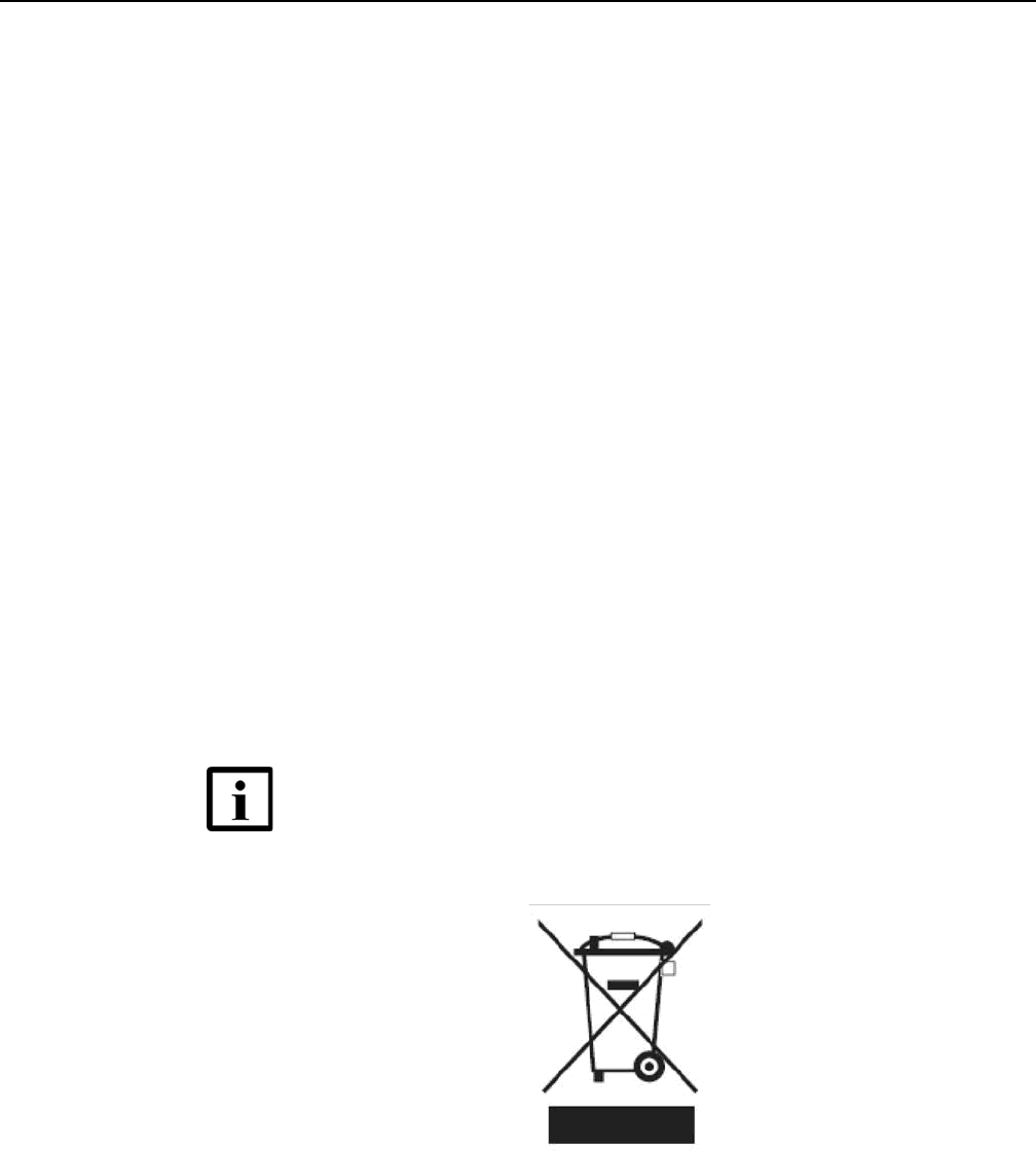
3.3.7 End-of-life collection and treatment
Electronic products bearing or referencing the symbol shown in Figure 7, when put
on the market within the European Union (EU), shall be collected and treated at the
end of their useful life, in compliance with applicable EU and local legislation. They
shall not be disposed of as part of unsorted municipal waste. Due to materials that
may be contained in the product, such as heavy metals or batteries, the environment
and human health may be negatively impacted as a result of inappropriate disposal.
Figure 7 Recycling/take back/disposal of product symbol
Note — In the European Union, a solid bar under the symbol for
a crossed-out wheeled bin indicates that the product was put on
the market after 13 August 2005.
DRAFT

ETSI environmental and CRoHS guidelines
32
7368 ISAM ONT G-240W-F Product Guide
Edition 01 Issue: 01
At the end of their life, the OLT and ONT products are subject to the applicable local
legislations that implement the European Directive 2012/19EU on waste electrical
and electronic equipment (WEEE).
There can be different requirements for collection and treatment in different member
states of the European Union.
In compliance with legal requirements and contractual agreements, where
applicable, Nokia will offer to provide for the collection and treatment of Nokia
products bearing the logo shown in Figure 7 at the end of their useful life, or products
displaced by Nokia equipment offers. For information regarding take-back of
equipment by Nokia, or for more information regarding the requirements for
recycling/disposal of product, contact your Nokia account manager or Nokia take
back support at sustainability.global@nokia.com.
DRAFT
7368 ISAM ONT G-240W-F Product Guide ANSI ONT safety guidelines
Issue: 01 Edition 01 33
4 ANSI ONT safety guidelines
This chapter provides information about the mandatory regulations that govern the
installation and operation of the optical network terminals or units (ONTs or ONUs)
in the North American or ANSI market.
4.1 Safety instructions
This section describes the safety instructions that are provided in the ONT customer
documentation and on the equipment.
4.1.1 Safety instruction boxes in customer
documentation
The safety instruction boxes are provided in the ONT customer documentation.
Observe the instructions to meet safety requirements.
The following is an example of the Danger box.
The Danger box indicates that the described activity or situation may pose a threat
to personal safety. It calls attention to a situation or procedure which, if not correctly
performed or adhered to, may result in death or serious physical harm.
Do not proceed beyond a Danger box until the indicated conditions are fully
understood and met.
The following is an example of the Warning box.
The Warning box indicates that the described activity or situation may, or will, cause
equipment damage, loss of data, or serious performance problems. It identifies a
possible equipment-damaging situation or provides essential information to avoid the
degradation of system operations or data.
Do not proceed beyond a warning until the indicated conditions are fully understood
and met.
Danger — Possibility of personal injury.
Warning 1 — Possibility of equipment damage.
Warning 2 — Possibility of data loss.
DRAFT
ANSI ONT safety guidelines
34
7368 ISAM ONT G-240W-F Product Guide
Edition 01 Issue: 01
The following is an example of the Caution box.
The Caution box indicates that the described activity or situation may, or will, cause
service interruption.
Do not proceed beyond a caution until the indicated conditions are fully understood
and met.
The following is an example of the Note box.
The Note box provides information that assists the personnel working with ONTs. It
does not provide safety-related instructions.
4.1.2 Safety-related labels
The ONT equipment is labeled with specific safety compliance information and
instructions that are related to a variant of the ONT. Observe the instructions on the
safety labels.
Table 2 provides examples of the text in the various ONT safety labels.
Table 2 Safety labels
Caution 1 — Possibility of service interruption.
Caution 2 — Service interruption.
Note — Information of special interest.
Description Label text
UL compliance Communication service equipment US listed. Type 3R enclosure -
Rainproof.
TUV compliance Type 3R enclosure - Rainproof.
ESD warning Caution: This assembly contains electrostatic sensitive device.
Laser classification Class 1 laser product
Laser product compliance This laser product conforms to all applicable standards of 21 CFR
1040.10 at date of manufacture.
FCC standards compliance Tested to comply with FCC standards for home or office use.
CDRH compliance Complies with 21 CFR 1040.10 and 1040.11 except for deviations
pursuant to Laser Notice No. 50, dated June 24, 2007
(1 of 2)
DRAFT
7368 ISAM ONT G-240W-F Product Guide ANSI ONT safety guidelines
Issue: 01 Edition 01 35
Figure 8 shows a sample safety label on the ONT equipment.
Figure 8 Sample safety label on the ONT equipment
4.2 Safety standards compliance
This section describes the ONT compliance with North American safety standards.
Operation conditions This device complies with Part 15 of the FCC Rules. Operation is
subject to the following two conditions: (1) this device may not cause
harmful interference, and (2) this device must accept any interference
received, including interference that may cause undesired operation.
Canadian standard
compliance (modular ONT)
This Class A digital apparatus complies with Canadian ICES-003.
Canadian standard
compliance (outdoor ONT)
This Class B digital apparatus complies with Canadian ICES-003.
CE marking There are various CE symbols for CE compliance.
Description Label text
(2 of 2)
18533
This device complies with Part 15 of the FCC Rules. Operation is subject
to the following two conditions: (1) this device may not cause harmful
interference, and (2) this device must accept any interference
received, including interference that may cause undesired operation.
This Class A digital apparatus complies with Canadian ICES-003. Cet appareil
numerique de la class A est conforme a la norme NMB-003 du Canada
Tested to Comply
with FCC Standards
FOR HOME OR OFFICE USE
COMMUNICATION SERVICE EQUIPMENT
US LISTED
27FY
Type 3R Enclosure - Rainproof
CAUTION
This Assembly Contains Electrostatic Sensitive Devices
c
®
Warning — Changes or modifications to this unit not expressly
approved by the party responsible for compliance could void
the user's authority to operate the equipment.
DRAFT

ANSI ONT safety guidelines
36
7368 ISAM ONT G-240W-F Product Guide
Edition 01 Issue: 01
4.2.1 EMC, EMI, and ESD standards compliance
The ONT equipment complies with the following requirements:
•Federal Communications Commission (FCC) CFR 47, Part 15, Subpart B, Class
A requirements for OLT equipment
•GR-1089-CORE requirements, including:
•Section 3 Electromagnetic Interference, Emissions Radiated and Conducted
•Section 3 Immunity, Radiated and Conducted
•Section 2 ESD Discharge Immunity: System Level Electrostatic Discharge and EFT
Immunity: Electrically Fast Transients
This equipment has been tested and found to comply with the limits for a Class B
digital device, pursuant to Part 15 of the FCC Rules. These limits are designed to
provide reasonable protection against harmful interference in a residential
installation. This equipment generates, uses and can radiate radio frequency energy
and, if not installed and used in accordance with the instructions, may cause harmful
interference to radio communications.
However, there is no guarantee that interference will not occur in a particular
installation. If this equipment does cause harmful interference to radio or television
reception, which can be determined by turning the equipment off and on, the user is
encouraged to try to correct the interference by one or more of the following
measures:
•Reorient or relocate the receiving antenna.
•Increase the separation between the equipment and receiver.
•Connect the equipment into an outlet on a circuit different from that to which the
receiver is needed.
•Consult the dealer or an experienced radio/TV technician for help.
4.2.2 Equipment safety standard compliance
The ONT equipment complies with the requirements of UL60950-1, Outdoor ONTs
to “Communication Service Equipment” (CSE) and Indoor ONTs to Information
Technology Equipment (ITE).
DRAFT

7368 ISAM ONT G-240W-F Product Guide ANSI ONT safety guidelines
Issue: 01 Edition 01 37
4.2.3 Environmental standards compliance
The ONT equipment complies with the following standards:
•GR-63-CORE (NEBS): requirements related to operating, storage, humidity,
altitude, earthquake, office vibration, transportation and handling, fire resistance
and spread, airborne contaminants, illumination, and acoustic noise
•GR-487-CORE: requirements related to rain, chemical, sand, and dust
•GR-487 R3-82: requirements related to condensation
•GR-3108: Requirements for Network Equipment in the Outside Plant (OSP)
•TP76200: Common Systems Equipment Interconnections Standards
4.2.4 Laser product standards compliance
The ONT equipment complies with 21 CFR 1040.10 and CFR 1040.11, except for
deviations pursuant to Laser Notice No. 50, dated June 24, 2007” or to 21 CFR
1040.10 U.S. Center for Devices and Radiological Health (CDRH) of the Food and
Drug Administration (FDA) Laser Notice 42 for ONTs containing Class 1 Laser
modules certified by original manufactures.
Per CDRH 21 CFR 10.40.10 (h) (1) (iv) distributors of Class 1 laser products, such
as Nokia ONTs shall leave the following Laser Safety cautions with the end user.
a) “Class 1 Laser Product”
b) “Caution – Use of controls or adjustments or performance of procedures other
than those specified herein may result in hazardous radiation exposure.”
Figure 9 shows a laser product label.
Figure 9 Sample laser product label showing CDRH 21 CFR compliance
FiOS Enabled
To Order FiOS: 888 GET-FiOS
or visit Verizon.com
For Service: 888 553-1555
2301 Sugar Bush Rd.
Raleigh, NC 27612
No User Serviceable Parts Inside. Refer All Servicing To Qualified Personnel.
Complies with 21 CFR 1040.10 and
1040.11 except for deviations pursuant to
Laser Notice No. 50, dated June 24, 2007.
4P92
I.T.E 12VDC 2.5A
22813
DRAFT

ANSI ONT safety guidelines
38
7368 ISAM ONT G-240W-F Product Guide
Edition 01 Issue: 01
4.2.5 Resistibility requirements compliance
The ONT equipment complies with the requirements of ITU Recommendation K.21
for resistibility of telecommunication equipment installed in customer premises to
overvoltage and overcurrents.
4.3 Laser safety guidelines
Only qualified service personnel who are extremely familiar with laser radiation
hazards should install or remove the fiber optic cables and units in this system.
Observe the following warnings when you perform installation, operations, and
maintenance tasks on the ONT equipment.
Observe the following danger for a laser hazard. Eyes can be damaged when they
are exposed to a laser beam. Take necessary precautions before you plug in the
optical modules.
Per CDRH 21 CFR 10.40.10 (h) (1) (iv) distributors of Class 1 laser products, such
as Nokia ONTs shall leave the following Laser Safety cautions with the end user.
a) “Class 1 Laser Product”
b) “Caution – Use of controls or adjustments or performance of procedures other
than those specified herein may result in hazardous radiation exposure.”
4.3.1 Laser warning labels
The following figures show sample labels related to laser product, classification and
warning.
Figure 10 shows a laser product label.
Danger — There may be invisible laser radiation at the fiber
optic cable when the cable is removed from the connector.
Avoid direct exposure to beam.
Danger — Possibility of equipment damage. Risk of eye
damage by laser radiation.
DRAFT
7368 ISAM ONT G-240W-F Product Guide ANSI ONT safety guidelines
Issue: 01 Edition 01 39
Figure 10 Laser product label
Figure 11 shows a laser classification label. Laser classification labels may be
provided in other languages.
Figure 11 Laser classification label
Figure 12 shows a laser warning label and an explanatory label for laser products.
Explanatory labels may be provided in other languages. The explanatory label
provides the following information:
•a warning that calls attention to the invisible laser radiation
•an instruction against staring into the beam or viewing directly with optical
instruments
•wavelength
•normal output power
•maximum output power
18455
LASER CLASSE 1CLASE 1 DEL LASER
CLASS 1 LASER PRODUCT PRODUCTO LASER CLASE 1
18992
'
'
DRAFT
ANSI ONT safety guidelines
40
7368 ISAM ONT G-240W-F Product Guide
Edition 01 Issue: 01
Figure 12 Laser warning labels
4.3.2 Laser classification
The ONT is classified as a Class 1 laser product based on its transmit optical output.
For Class 1 laser products, lasers are safe under reasonably foreseeable conditions
of operation, including the use of optical instruments for intrabeam viewing.
Figure 13 shows a sample laser product safety label on the ONT equipment.
INVISIBLE LASER RADIATION
DO NOT STARE INTO BEAM
OR VIEW DIRECTLY WITH
OPTICAL INSTRUMENTS
Wavelength(s): xxxx nm
Normal output power: xx m W
Max output power: yyy m W
Laser Warning Label Laser Warning Label
CLASS 1 LASER PRODUCT
INVISIBLE LASER RADIATION PRESENT AT FIBER OPTIC CABLE
WHEN NOT CONNECTED. AVOID DIRECT EXPOSURE TO BEAM.
RAYONNEMENT LASER CLASSE 1
RAYONNEMENT LASER INVISIBLE
EVITER TOUTE EXPOSITION AU FAISCEAU
NE PAS DEMONTER. FAIRE APPEL A UN PERSONNELL QUALIFIE
CLASE 1 DEL LASER
RADIACION DE LASER INVISIBLE. EVITAR CUALOUIER EXPOSICION AL
RAYO LASER. NO DESMONTAR. LLAMAR A PERSONAL AUTORIZADO
Laser Warning Label
18993
'
DRAFT
7368 ISAM ONT G-240W-F Product Guide ANSI ONT safety guidelines
Issue: 01 Edition 01 41
Figure 13 Sample laser product safety label on the ONT equipment
4.3.3 Transmit optical output
The maximum transmit optical output of an ONT is +5 dBm.
4.3.4 Normal laser operation
In normal operation, fiber cable laser radiation is always off until it receives signal
from the line terminal card.
Operating personnel must observe the instructions on the laser explanatory label
before plugging in the optical module.
4.3.5 Location class
Use cable supports and guides to protect the receptacles from strain.
18532
3FE55851ABAA
Model:
MFG:
MONTH: XX
YEAR: XXXX
ICS: XX
MRev: XX
MAC:XXXXXXXXXXXX
SN:ALCLXXXXXXXX
FCC ID: XXXXXXXXXXX
This device complies with Part 15 of the FCC Rule.
Operation is subject to the following two conditions:
(1) This device may not cause harmful interference, and
(2) this device must accept any interference received,
including intereference that may cause undesired operation.
ASSEMBLED IN CHINA
2301 Sugar Bush Rd
.
Raleigh, NC 27612
DANGER - Invisible Laser radiation when open.
AVOID DIRECT EXPOSURE TO BEAM.
DANGER - Rayonnement Laser invisible lorsqu’elle
est ouverte. Evitee l’expostion direct au faisceau.
Complies with 21 CFR 1040.10 and 1040.11 except for deviations
pursuant to Laser Notice No. 50 dated June 24, 2007
12VDC 3A
I.T.E
Intertek
4006119
CLASS 1 LASER PRODUCT
PRODUIT LASER DE CLASSE 1
Danger — Risk of eye damage by laser radiation.
DRAFT

ANSI ONT safety guidelines
42
7368 ISAM ONT G-240W-F Product Guide
Edition 01 Issue: 01
4.4 Electrical safety guidelines
This section provides the electrical safety guidelines for the ONT equipment.
4.4.1 Power supplies
The use of any non-Nokia approved power supplies or power adapters is not
supported or endorsed by Nokia. Such use will void any warranty or support contract
with Nokia. Such use greatly increases the danger of damage to equipment or
property.
4.4.2 Cabling
The following are the guidelines regarding cables used for the ONT equipment:
•Use only cables approved by the relevant national electrical code.
•Use cables suitable for outdoor use for outdoor installation of ONTs.
•The ONTs have been evaluated for use with external POTS wiring without primary
protection that may not exceed 140 ft (43 m) in reach. However, the power cable
must not exceed 100 ft (31 m).
4.4.3 Protective earth
Earthing and bonding of the ONTs must comply with the requirements of NEC article
250 or local electrical codes.
4.5 ESD safety guidelines
The ONT equipment is sensitive to ESD. Operations personnel must observe the
following ESD instructions when they handle the ONT equipment.
Note — The ONTs comply with the U.S. National Electrical
Code. However, local electrical authorities have jurisdiction
when there are differences between the local and U.S.
standards.
Caution — This equipment is ESD sensitive. Proper ESD
protections should be used when entering the TELCO Access
portion of the ONT.
DRAFT

7368 ISAM ONT G-240W-F Product Guide ANSI ONT safety guidelines
Issue: 01 Edition 01 43
During installation and maintenance, service personnel must wear wrist straps to
prevent damage caused by ESD.
Nokia recommends that you prepare the site before you install the ONT equipment.
In addition, you must control relative humidity, use static dissipating material for
furniture or flooring, and restrict the use of air conditioning.
4.6 Environmental requirements
See the ONT technical specification documentation for temperature ranges for
ONTs.
During operation in the supported temperature range, condensation inside the ONT
caused by humidity is not an issue. To avoid condensation caused by rapid changes
in temperature and humidity, Nokia recommends:
•The door of the ONT not be opened until temperature inside and outside the
enclosure has stabilized.
•If the door of the ONT must be opened after a rapid change in temperature or
humidity, use a dry cloth to wipe down the metal interior to prevent the risk of
condensation.
•When high humidity is present, installation of a cover or tent over the ONT helps
prevent condensation when the door is opened.
DRAFT

ANSI ONT safety guidelines
44
7368 ISAM ONT G-240W-F Product Guide
Edition 01 Issue: 01
DRAFT

7368 ISAM ONT G-240W-F Product Guide G-240W-F unit data sheet
Issue: 01 Edition 01 45
5 G-240W-F unit data sheet
5.1 G-240W-F part numbers and identification
5.2 G-240W-F general description
5.3 G-240W-F software and installation feature support
5.4 G-240W-F interfaces and interface capacity
5.5 G-240W-F LEDs
5.6 G-240W-F detailed specifications
5.7 G-240W-F GEM ports and T-CONTs
5.8 G-240W-F performance monitoring statistics
5.9 G-240W-F functional blocks
5.10 G-240W-F standards compliance
5.11 G-240W-F special considerations
DRAFT

G-240W-F unit data sheet
46
7368 ISAM ONT G-240W-F Product Guide
Edition 01 Issue: 01
5.1 G-240W-F part numbers and identification
Table 3 provides part numbers and identification information for the G-240W-F
indoor ONT.
Table 3 Identification of G-240W-F indoor ONTs
Ordering kit
part number
Provisioning
part number
Description CLEI CPR ECI/
Bar
code
3FE 46649 AA 3FE 46597 AA Package P GPON indoor ONT with two POTS ports, four
10/100/1000 Base-T Ethernet interfaces, and one 100 mW Wi-Fi
radio with on/off switch.
This ONT features two USB 2.0 ports and supports SC/APC
optics.
Includes two 5dBI indoor multi-directional external WiFi antenna
(not detachable), one 1.5m CAT-5E Ethernet cable with RJ-45
endpoint, and one 1.5m RJ-11 cable.
Also includes one 2-pin wall-mounted 12V AC/DC power adapter
with US plug.
———
3FE 46649 AB 3FE 46597 AA Package P GPON indoor ONT with two POTS ports, four
10/100/1000 Base-T Ethernet interfaces, and one 200 mW Wi-Fi
radio with on/off switch.
This ONT features two USB 2.0 ports and supports SC/APC
optics.
Includes two 5dBI indoor multi-directional external WiFi antenna
(not detachable), one 1.5m CAT-5E Ethernet cable with RJ-45
endpoint, and one 1.5m RJ-11 cable.
Also includes one 2-pin wall-mounted 12V AC/DC power adapter
with US plug.
———
3FE 46649 AC
Customer-specific
3FE 46597 AA Package P GPON indoor ONT with two POTS ports, four
10/100/1000 Base-T Ethernet interfaces, and one 200 mW Wi-Fi
radio with on/off switch.
This ONT features two USB 2.0 ports and supports SC/APC
optics.
Includes two 5dBI indoor multi-directional external WiFi antenna
(not detachable), one 1.5m CAT-5E Ethernet cable with RJ-45
endpoint, and one 1.5m RJ-11 cable.
Also includes one 2-pin wall-mounted 12V AC/DC power adapter
with US plug.
———
3FE 46649 BA 3FE 46597 AA Package P GPON indoor ONT with two POTS ports, four
10/100/1000 Base-T Ethernet interfaces, and one 100 mW Wi-Fi
radio with on/off switch.
This ONT features two USB 2.0 ports and supports SC/APC
optics.
Includes two 5dBI indoor multi-directional WiFi external antenna
(not detachable), one 1.5m CAT-5E Ethernet cable with RJ-45
endpoint, and one 1.5m RJ-11 cable.
Also includes one 2-pin wall-mounted 12V AC/DC power adapter
with EU (European) plug.
———
(1 of 2)
DRAFT

7368 ISAM ONT G-240W-F Product Guide G-240W-F unit data sheet
Issue: 01 Edition 01 47
For the G-240W-F indoor ONT power supply information, contact your Nokia
technical support representative.
5.2 G-240W-F general description
G-240W-F indoor ONTs provide the subscriber interface for the network by
terminating the PON interface and converting it to user interfaces that directly
connect to subscriber devices. The ONT is compatible with all existing subscriber
equipment, including analog phones with both tone and rotary dial capabilities,
cordless phones, modems, fax machines, and caller ID boxes (Type I, Type II, and
Type III).
G-240W-F indoor ONTs provide the following functions:
•single fiber GPON interface with 1.244Gbit/s upstream and 2.488Gbit/s
downstream data rates
•4 Ethernet LAN connections
•2 POTS connections
•2 USB 2.0 ports; voltage rate: 5V, current rate: 500mA per port
•reset button
•LED indicators on/off button
•WLAN enable/disable button
•WPS enable/disable button
•UPnP IGD2.0 support
3FE 46649 BB
Customer-specific
3FE 46597 AB Package P GPON indoor ONT with two POTS ports, four
10/100/1000 Base-T Ethernet interfaces, and one 100 mW Wi-Fi
radio with on/off switch.
This ONT features two USB 2.0 ports and supports SC/APC
optics.
Includes two 5dBI indoor multi-directional WiFi external antenna
(not detachable), one 1.5m CAT-5E Ethernet cable with RJ-45
endpoint, and one 1.5m RJ-11 cable.
Also includes one 2-pin wall-mounted 12V AC/DC power adapter
with EU (European) plug.
———
3FE 46649 CA 3FE 46597 AA Package P GPON indoor ONT with two POTS ports, four
10/100/1000 Base-T Ethernet interfaces, and one 100 mW Wi-Fi
radio with on/off switch.
This ONT features two USB 2.0 ports and supports SC/APC
optics.
Includes two 5dBI indoor multi-directional WiFi external antenna
(not detachable), one 1.5m CAT-5E Ethernet cable with RJ-45
endpoint, and one 1.5m RJ-11 cable.
Also includes one 3-pin wall-mounted 12V AC/DC power adapter
with UK (British) plug.
———
Ordering kit
part number
Provisioning
part number
Description CLEI CPR ECI/
Bar
code
(2 of 2)
DRAFT

G-240W-F unit data sheet
48
7368 ISAM ONT G-240W-F Product Guide
Edition 01 Issue: 01
•2.4 GHz wireless interface
•2 5dBI indoor multi-directional external WiFi antenna (not detachable)
•MIMO
•support for up to 20 concurrent wireless connections
•802.11b/g/n compliant
•MDI/MDIX auto sensing
•auto-negotiation for speed and duplex
•multiple voice Codec
•echo cancellation
•Analog Telephone Adapter (ATA) function integrated based on SIP (RFC3261)
and H.248, with various CLASS services supported, including Caller ID, Call
Waiting, Call Forwarding, and Call Transfer
•auto reconnect when connection to server is lost
•Network Address Translation (NAT)
•3 REN per line
5.2.1 TR-069 support
The ONT supports the reading of optical parameters via TR-069:
•laser bias current
•voltage
•temperature
•received signal levels
•lower thresholds
These are the same optical parameters supported in the GUI. For more information,
see Table 21 in the chapter “Configure a G-240W-F indoor ONT”.
The ONT supports the status retrieval and configuration of the following Wi-Fi
parameters via TR-069:
•channel
•SSID
•password for WPA and WEP
•Tx power (transmission rate in dBm)
These are the same TR-069 object parameters that are supported in the GUI. For
more information, see Tables 17 and 26 in the chapter “Configure a G-240W-F
indoor ONT”.
The ONT also supports TR-069 statistics and troubleshooting for LAN, WAN, and
WiFi.
DRAFT

7368 ISAM ONT G-240W-F Product Guide G-240W-F unit data sheet
Issue: 01 Edition 01 49
5.2.2 TR-104 parameter extension support for voice
service
A proprietary attribute has been added to the TR-104 Voice Service object structure
to enable the ACS to configure the name of the embedded GSIP XML file to be
selected.
The TR-104 Voice Service Object is:
InternetGatewayDevice.Services.VoiceService.{i}.Capabilities.SIP.
The proprietary attribute is: X_ALU-COM_XML_File_Name_Path.
5.2.3 TR-181 Wi-Fi objects adapted in TR-098
TR-181 is the device data model for TR-069 Wi-Fi objects.
The following TR-181 Wi-Fi objects (and sub-objects) adapted in TR-098 are
supported in this release:
•Device.WiFi
•Device.WiFi.Radio.{i}.
•Device.WiFi.Radio.{i}.Stats.
•Device.WiFi.SSID.{i}.
•Device.WiFi.SSID.{i}.Stats.
•Device.WiFi.AccessPoint.{i}.
•Device.WiFi.AccessPoint.{i}.Security.
•Device.WiFi.AccessPoint.{i}.WPS.
•Device.WiFi.AccessPoint.{i}.AssociatedDevice{i}.
•Device.WiFi.Endpoint.{i}.
•Device.WiFi.Endpoint.{i}.Stats.
•Device.WiFi.Endpoint.{i}.Security.
•Device.WiFi.Endpoint.{i}.Profile{i}.
•Device.WiFi.Endpoint.{i}.Profile{i}.Security.
•Device.WiFi.Endpoint.{i}.WPS.
•Device.WiFi.NeighboringWiFiDiagnostics.
•Device.WiFi.NeighboringWiFiDiagnostics.Result.{i}.
5.2.4 Mobile offload support
As part of the E2E solution supported by the ISAM 7750 service router, the
G-240W-F ONT offers Mobile Offload support using a combination of EAP-SIM and
ITU-T 802.11.
DRAFT

G-240W-F unit data sheet
50
7368 ISAM ONT G-240W-F Product Guide
Edition 01 Issue: 01
EAP-SIM is an authentication method that uses the user credentials on the SIM card
and EAP to authenticate the user with the Wi-Fi network, removing the need for user
input (username and password).
A dedicated public mobile offload SSID in the ONT enables mobile subscribers to
connect to the Internet. Encryption is supported by 802.11, providing seamless Wi-Fi
authentication for SIM-based user equipment.
The ONT acts as the RADIUS client and sends the encapsulated EAP messages to
the AAA server via the WLAN Gateway, which acts as the RADIUS proxy server. The
interaction between the ONT and the AAA server provides subscriber management
for authenticated mobile users without adding authentication load to the 3G network.
5.2.5 Bridged Residential Gateway (BRG) support
The BRG receives IP addresses for the WAN interface using DHCP or PPPoE. The
BRG can use either Ipv4 or Ipv6 addresses. BRG uses OpenFlow protocol version
1.3.1 to manage Access Control List entries and routing protocols. TR-069 can be
used to manage the local DHCP server and the soft GRE tunnel.
The BRG supports the encapsulation of Ethernet frames from different bridges in the
GRE tunnel to the access tunnel. Multiple bridges can map to the same GRE tunnel.
Where encapsulated packets exceed the MTU (packet size), fragmentation is also
supported.
Upstream QoS can reserve bandwidth for public and private Wi-Fi bridges, based on
profiles defined for the access uplink speed. A unique VLAN tag can be configured
for each SSID on the BRG. Unicast QoS adjustment can be enabled to support
Multicast IPTV
Liveness detection and redundancy, link failure notification, and DHCP local server
fallback are provided to help manage potential problems with gateway access. Event
notification via TR-069 reports when the PON link is up and the tunnel is
unreachable.
5.2.6 Support for soft GRE tunnels
This section describes the support for soft GRE tunnels for integration with the 7750
Service Router WLAN gateway. The Nokia 7750 Service Router WLAN GW can
accept soft GRE tunnels from any IP Source Address, in a preconfigured Subnet or
Access Control List, or MPLS label.
DRAFT

7368 ISAM ONT G-240W-F Product Guide G-240W-F unit data sheet
Issue: 01 Edition 01 51
5.2.6.1 GRE
Generic Routing Encapsulation (GRE) is a tunneling protocol that can encapsulate a
wide variety of network layer protocols inside virtual point-to-point links over an
Internet Protocol network. GRE provides a secure path for transporting packets
through a public network. In essence, GRE creates a private P2P connection, similar
to a VPN, between clients and servers. GRE is the preferred transport mechanism
between the Carrier Wi-Fi access network and the WLAN GW.
GRE works by encapsulating a payload (an inner packet that needs to be delivered
to a destination network) inside an outer IP packet. GRE tunnel endpoints send
payloads through GRE tunnels by routing encapsulated packets through intervening
IP networks. The inner packets are not parsed along the way; only the outer IP
packets are parsed as they are forwarded towards the GRE tunnel endpoint, where
the GRE encapsulation is removed, and the payload is forwarded to its final
destination.
5.2.6.2 Soft GRE
In soft GRE, only one side of the tunnel needs to be configured; the other end learns
the remote IP addresses of all remote tunnel endpoints by examining the incoming
GRE packets.
GRE tunnels can be automatically created when devices attach to the AP,
eliminating the need for each AP to be explicitly provisioned on the WLAN Gateway.
Because this soft GRE is stateless and the tunnel contexts are created based on
need, the WLAN Gateway does not need to maintain states for unused tunnels,
which improves scalability.
The operator can restrict the traffic going through the GRE tunnel based on the
SSIDs or LAN ports.
Figure 14 illustrates the soft GRE architecture.
DRAFT
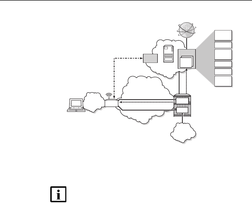
G-240W-F unit data sheet
52
7368 ISAM ONT G-240W-F Product Guide
Edition 01 Issue: 01
Figure 14 SoftGRE-based architecture
For more information about soft GRE architecture and configuration procedures, see
the 7368 Configuration, Management, and Troubleshooting guide, which contains
the vCPE User Guide.
5.3 G-240W-F software and installation feature
support
For information on installing or replacing the G-240W-F see:
•Install a G-240W-F indoor ONT
•Replace a G-240W-F indoor ONT
For information on the following topics, see the 7368 ISAM ONT Product Overview
Guide:
•ONT and MDU general descriptions of features and functions
•Ethernet interface specifications
Note — While the vCPE forwards all traffic over the GRE
tunnel, the soft GRE architecture for the G-240W-F enables the
operator to restrict the traffic over the GRE tunnel bases on
SSIDs or LAN ports.
DHCP
server
Motive
Access Network
Security
Diag.
Qos
Viurs
scanner
Parental
Cntl
BW on
Demand
Basic
vCPE
VSR
Home
Network
VLAN: 100
Soft-GRE
Tunnel
TR-069 VLAN: 881
IPTV VLAN: 981
Mgmt
IPTV
Network
BRG
25265
DRAFT

7368 ISAM ONT G-240W-F Product Guide G-240W-F unit data sheet
Issue: 01 Edition 01 53
•POTS interface specifications
•RSSI specifications
•Wi-Fi specifications
•ONT optical budget
•SLID entry via Ethernet port
•ONT management using an ONT interface
5.4 G-240W-F interfaces and interface capacity
Table 4 describes the supported interfaces and interface capacity for G-240W-F
indoor ONTs.
Table 4 G-240W-F indoor ONT interface connection capacity
Note
(1) The G-240W-F ONTs provide Wi-Fi service that is enabled and disabled using a Wi-Fi on/off switch.
5.4.1 G-240W-F connections and components
Figure 15 shows the physical connections on the back of the G-240W-F indoor
ONTs: USB, LAN, POTS, power input, and on/off button.
ONT type
and model
Maximum
capacity
POTS 10/ 100
BASE-T
10/ 100/ 1000
BASE-T
RF video
(CATV)
MoCA VDSL2 E1/T1 Local
craft
GPON SC/APC
G-240W-F
(1)
2—4 —————1
DRAFT
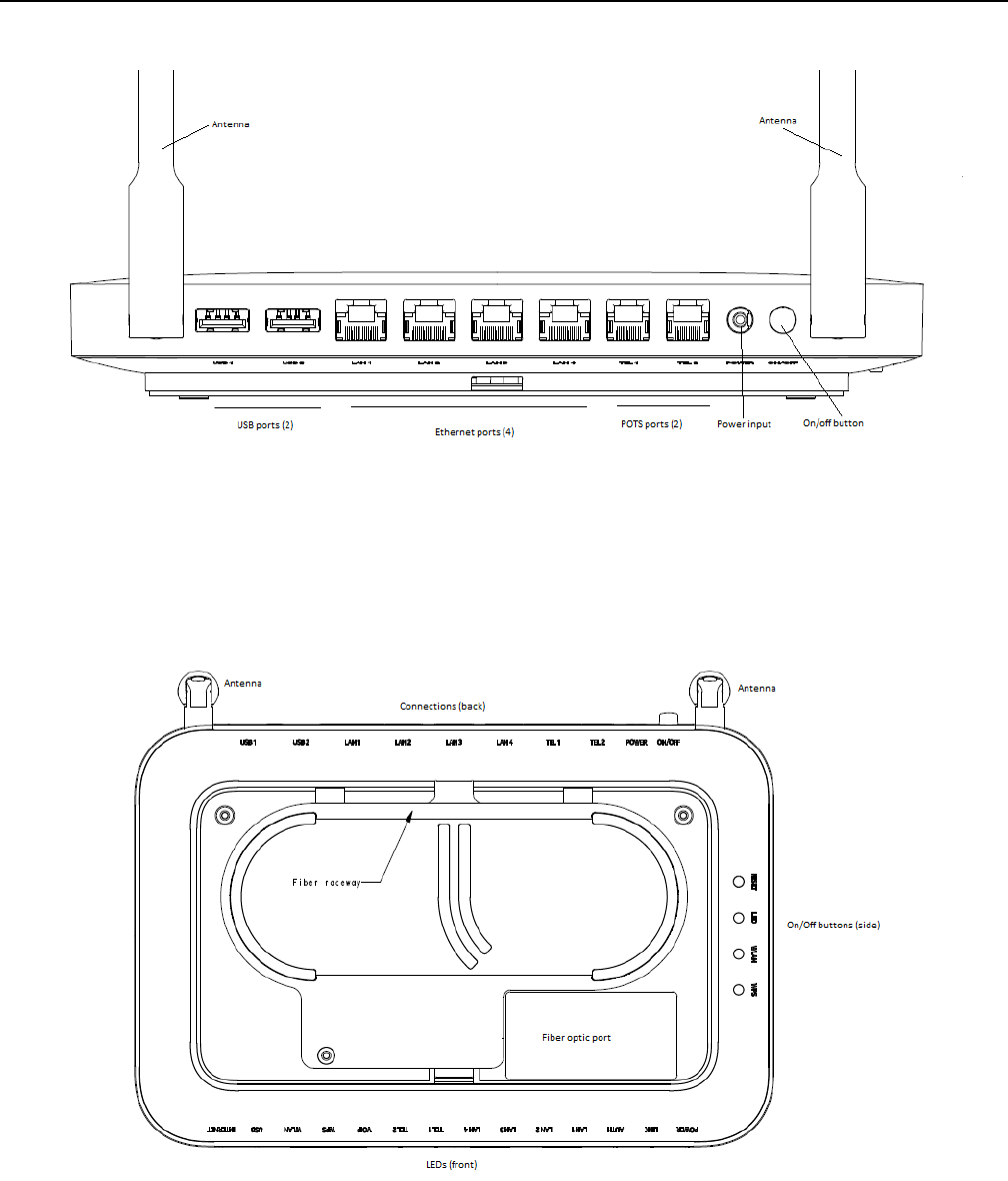
G-240W-F unit data sheet
54
7368 ISAM ONT G-240W-F Product Guide
Edition 01 Issue: 01
Figure 15 G-240W-F indoor ONT physical connections (back view)
Figure 16 shows the buttons on the side of the G-240W-F indoor ONTS: reset, LED
indicators on/off, WLAN enable/disable, and WPS enable/disable, as well as the fiber
optic port on the bottom of the ONT.
Figure 16 G-240W-F ONT Reset, LED, WLAN, and WPS buttons and fiber optic connection
(bottom and side view)
DRAFT

7368 ISAM ONT G-240W-F Product Guide G-240W-F unit data sheet
Issue: 01 Edition 01 55
Table 5 describes the physical connections for G-240W-F indoor ONTs.
Table 5 G-240W-F indoor ONT physical connections
Note
(1) The primary path for the earth ground for these ONTs is provided by the 12V Return signal in the power
connector.
5.5 G-240W-F LEDs
Figure 17 shows the G-240W-F indoor ONT LEDs.
Connection (1) Description
USB
(USB port)s
This connection is provided through two USB 2.0 ports on the back of the ONT.
The voltage rate is 5V, and the current rate is 500mA per port.
LAN1-LAN4
(RJ-45 Ethernet ports)
This connection is provided through Ethernet RJ-45 connectors on the back of the
ONT. Up to four 10/100/1000 Base-T Ethernet interfaces are supported.The
Ethernet ports can support both data and in-band video services on all four
interfaces.
TEL1, TEL2
(RJ-11 POTS ports)
This connection is provided through RJ-11 ports on the back of the ONT. Up to two
POTS connections are supported. The POTS ports support voice services.
POWER
(Power input)
This connection is provided through the power connector on the back of the ONT.
A power cable fitted with a barrel connector is used to make the connection.
ON/OFF This button on the side of the ONT turns the ONT on or off.
RESET Pressing the Reset button, located on the side of the ONT, for less than 10
seconds reboots the ONT; pressing the Reset button for 10 seconds resets the
ONT to the factory defaults, except for the LOID and SLID.
LED
(LED indicator button)
This button, located on the side of the ONT, turns all LED indicators on or off.
WLAN
(Wireless On/Off button)
Wi-Fi service is compliant with IEEE 802.11 standards and is enabled or disabled
using the WLAN button on the side of the ONT.
WPS
(Wi-Fi security button)
The Wi-Fi Protected Setup (WPS) button, located on the side of the ONT, enables
and disables WLAN data encryption.
PON
(Fiber optic port)
This connection, on the bottom of the ONT, is provided through an SC/APC fiber
optic connector.
DRAFT
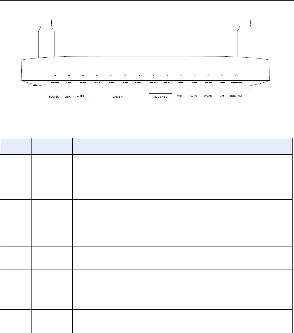
G-240W-F unit data sheet
56
7368 ISAM ONT G-240W-F Product Guide
Edition 01 Issue: 01
Figure 17 G-240W-F indoor ONT LEDs
Table 6 provides LED descriptions for G-240W-F indoor ONTs.
Table 6 G-240W-F indoor ONT LEDs
Indicator LED color and
behavior
LED behavior description
Power Green solid
Red solid
Off
Power on
Light failed on startup (for example corrupt flash), or self test failed on startup, or self test failed during
regular operation or when executed over OMCI
Power off
Link Green solid
Off
GPON link between ONT and OLT is operating normally
GPON link is down or no link connected
Auth Green solid
Green flashing
Off
ONT is authorized
ONT is In process of ranging or synchronizing on OMCI
ONT is not authorized
LAN 1 to 4 Green solid
Green flashing
Off
Ethernet is linked
LAN activity is present (in either direction)
ONT power off or Ethernet not connected
TEL 1 to 2 Green solid
Green flashing
Off
Phone off hook
Phone in ‘call in’ or ‘talking’ condition
Phone on hook
VOIP Green solid
Off
VOIP service is built up and can provide service
VOIP service is not built up or out of service
WPS Green solid
Green flashing
Off
WiFi protected setup link is up (negotiation and auto-configuration successful)
WiFi protected setup link activity (negotiation and auto-configuration ongoing)
WiFi protected setup link down or no link connected (negotiation has not started or has failed)
WLAN Green solid
Green flashing
Off
WLAN link is up (wireless enabled)
WLAN activity (traffic on wireless link)
WLAN link is down or no link is connected
(1 of 2)
DRAFT

7368 ISAM ONT G-240W-F Product Guide G-240W-F unit data sheet
Issue: 01 Edition 01 57
5.6 G-240W-F detailed specifications
Table 7 lists the physical specifications for G-240W-F indoor ONTs.
Table 7 G-240W-F indoor ONT physical specifications
Table 8 lists the power consumption specifications for G-240W-F indoor ONT.
Table 8 G-240W-F indoor ONT power consumption specifications
Table 9 lists the environmental specifications for G-240W-F indoor ONT.
USB Green solid
Green flashing
Off
At least one USB device is connected
Traffic activity on at least on USB device
No USB device connected
INTERNET Green solid
Green flashing
Off
HSI WAN is connected: a) the device has an IP address assigned from IPCP, DHCP, or static, and no
traffic has been detected; b) the session is dropped due to idle timeout but the PON link is still present.
PPPoE or DHCP connection in progress
HSI WAN is not connected: a) there is no physical interface connection; b) the device is in bridged mode
without an assigned IP address; c) the session has been dropped for reasons other than idle timeout.
Indicator LED color and
behavior
LED behavior description
(2 of 2)
Description Specification
Width 8.1 in. (205 mm)
Length 6 in. (152 mm)
7 in. (176 mm with antenna
Height 1.3 in. (33 mm)
Weight [within ± 0.5 lb (0.23 kg)] 0.88 lb (0.4 kg)
Maximum
power (Not
to exceed)
Condition Minimum
power
Condition
13.6 W 2 POTS off-hook, 4 10/100/1000
Base-T Ethernet, Wi-Fi operational
3.06 W 2 POTS on-hook, other
interfaces/services not provisioned
DRAFT
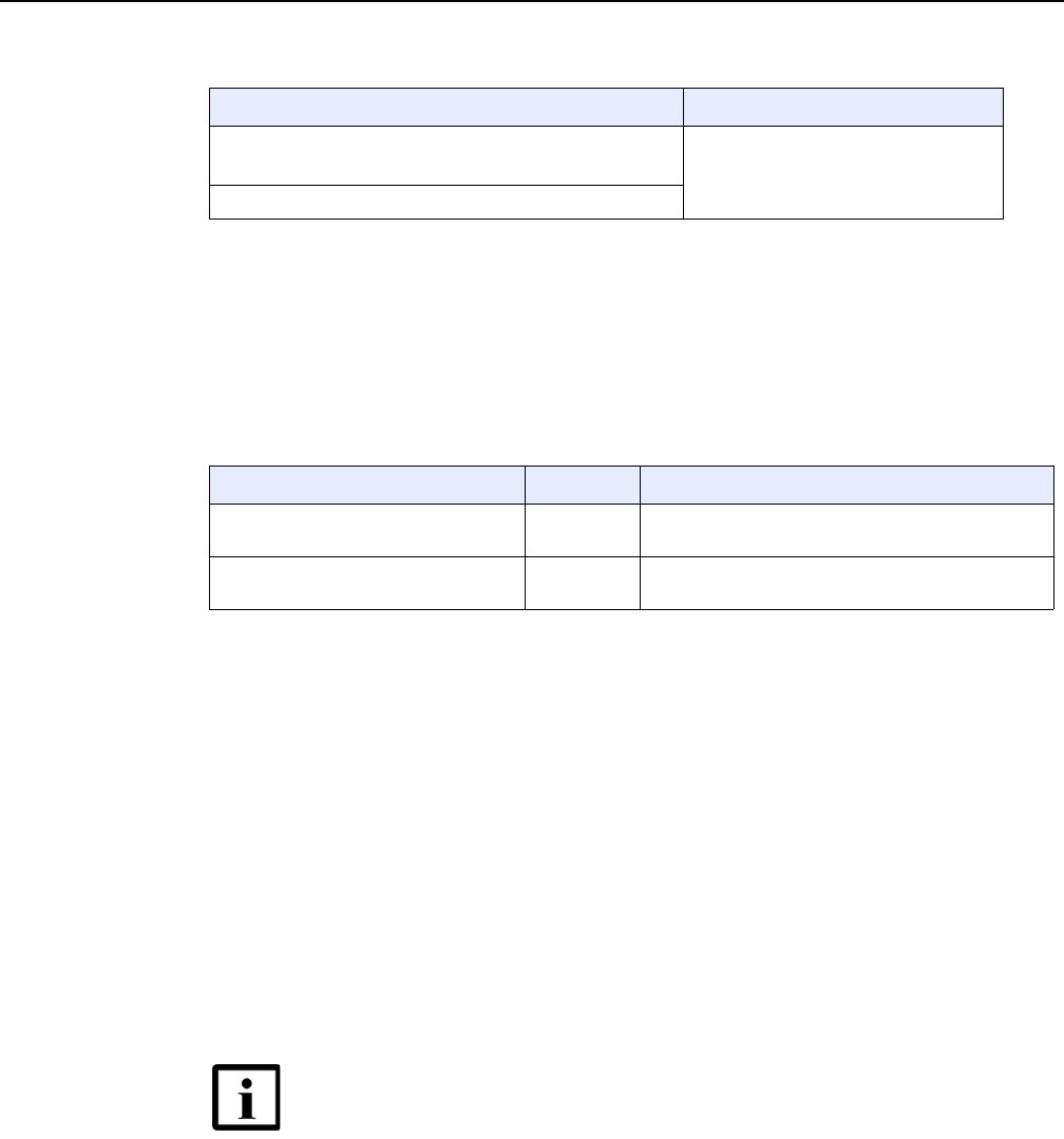
G-240W-F unit data sheet
58
7368 ISAM ONT G-240W-F Product Guide
Edition 01 Issue: 01
Table 9 G-240W-F indoor ONT environmental specifications
5.7 G-240W-F GEM ports and T-CONTs
Table 10 lists the maximum number of supported T-CONTs and GEM ports.
Table 10 G-240W-F indoor ONT capacity for GEM ports and T-CONTs
5.8 G-240W-F performance monitoring statistics
The following section identifies the supported performance monitoring statistics for
G-240W-F ONTs. A check mark indicates the statistic is supported on that ONT. An
empty cell indicates the statistic is not supported. The following tables are
categorized by supported alarm types:
•Table 11 provides statistics for ONTENET type counters
•Table 12 provides statistics for ONTL2UNI type counters
•Table 13 provides statistics for PONONTTC, PONONTMCTC, PONONTTCHSI,
PONONTTCCES, PONONTTCFLOW, and PONONTTCVOIP type counters
•Table 14 provides statistics for PONONTTC aggregate type counters
Temperature range and humidity Altitude
Operating: 23°F to 113 F (-5°C to 45°C) ambient temperature
5% to 95% relative humidity, non-condensing
Contact your Nokia technical support
representative for more information
Storage: -4°F to 158°F (-20°C to 70C)
GEM ports or TCONTs Maximum Notes
GEM ports per indoor or outdoor ONT 256 254 are present; 122 are available, and 2 are
reserved for multicast and debugging
T-CONTs per indoor or outdoor ONT 32 32 are present; 31 are available, and 1 is reserved
for OMCI
Note — If you have trouble accessing G-240W-F ONTs
performance monitoring statistics using TL1, please contact
your Nokia support representative for more information about
how to access and retrieve performance monitoring type
counters.
DRAFT

7368 ISAM ONT G-240W-F Product Guide G-240W-F unit data sheet
Issue: 01 Edition 01 59
Table 11 Package P ONTs ONTENET performance monitoring statistics
Note
(1) A 5 second polling window limitation exists on the ONT, therefore the margin of error for each 15-min window
is 5 seconds
Table 12 Package P ONTs ONTL2UNI performance monitoring statistics
Note
(1) A 5 second polling window limitation exists on the ONT, therefore the margin of error for each 15-min window
is 5 seconds
Table 13 Package P ONTs PONONTTC, PONONTMCTC, PONONTTCHSI,
PONONTTCCES, PONONTTCFLOW, PONONTTCVOIP perfor-
mance monitoring statistics
Note
(1) A 5 second polling window limitation exists on the ONT, therefore the margin of error for each 15-min window
is 5 seconds
ONT ONTENET statistics
FCSE
EC
LC
RBO
SCF
MCF
DT
IMTE
CSE
AE
IMRE
FTL
TBO
SQE
G-240W-F (1) ✓✓✓✓✓✓✓✓✓✓✓✓✓✓
ONT ONTL2UNI statistics
FRAMES
BYTES
MCFRAMES
DSDRPDFRMS
USDRPDFRMS
USFRAMES
DSFRAMES
USBYTES
DSBYTES
USMCFRAMES
DSMCFRAMES
G-240W-F (
1)
✓✓✓✓✓✓✓✓✓✓✓
ONT PONONTTC, PONONTMCTC, PONONTTCHSI, PONONTTCCES,
PONONTTCFLOW, PONONTTCVOIP statistics
TXBLOCKS
TXFRAGS
RXBLOCKS
RXFRAGS
LOSTFRAGS
BADGEMHDRS
G-240W-F (1) ✓✓✓✓✓
DRAFT

G-240W-F unit data sheet
60
7368 ISAM ONT G-240W-F Product Guide
Edition 01 Issue: 01
Table 14 Package P ONTs PONONTTC aggregate performance monitor-
ing statistics
Note
(1) A 5 second polling window limitation exists on the ONT, therefore the margin of error for each 15-min window
is 5 seconds
5.9 G-240W-F functional blocks
G-240W-F indoor ONTs are single-residence ONTs that support Wireless (Wi-Fi)
service. Wi-Fi services on these ONTs are compliant with the IEEE 802.11 standard
and enabled or disabled using a WLAN button. In addition to the Wi-Fi service, these
ONTs transmit Ethernet packets to four RJ-45 Ethernet ports and voice traffic to two
RJ-11 POTS ports. These ONTs also feature fiber optic, USB, and power
connectors.
Figure 18 shows the functional blocks for G-240W-F indoor ONT.
ONT PONONTTC (aggregate) statistics
TXBLOCKS
TXFRAGS
RXBLOCKS
RXFRAGS
LOSTFRAGS
BADGEMHDRS
G-240W-F (1) ✓✓✓✓✓
DRAFT
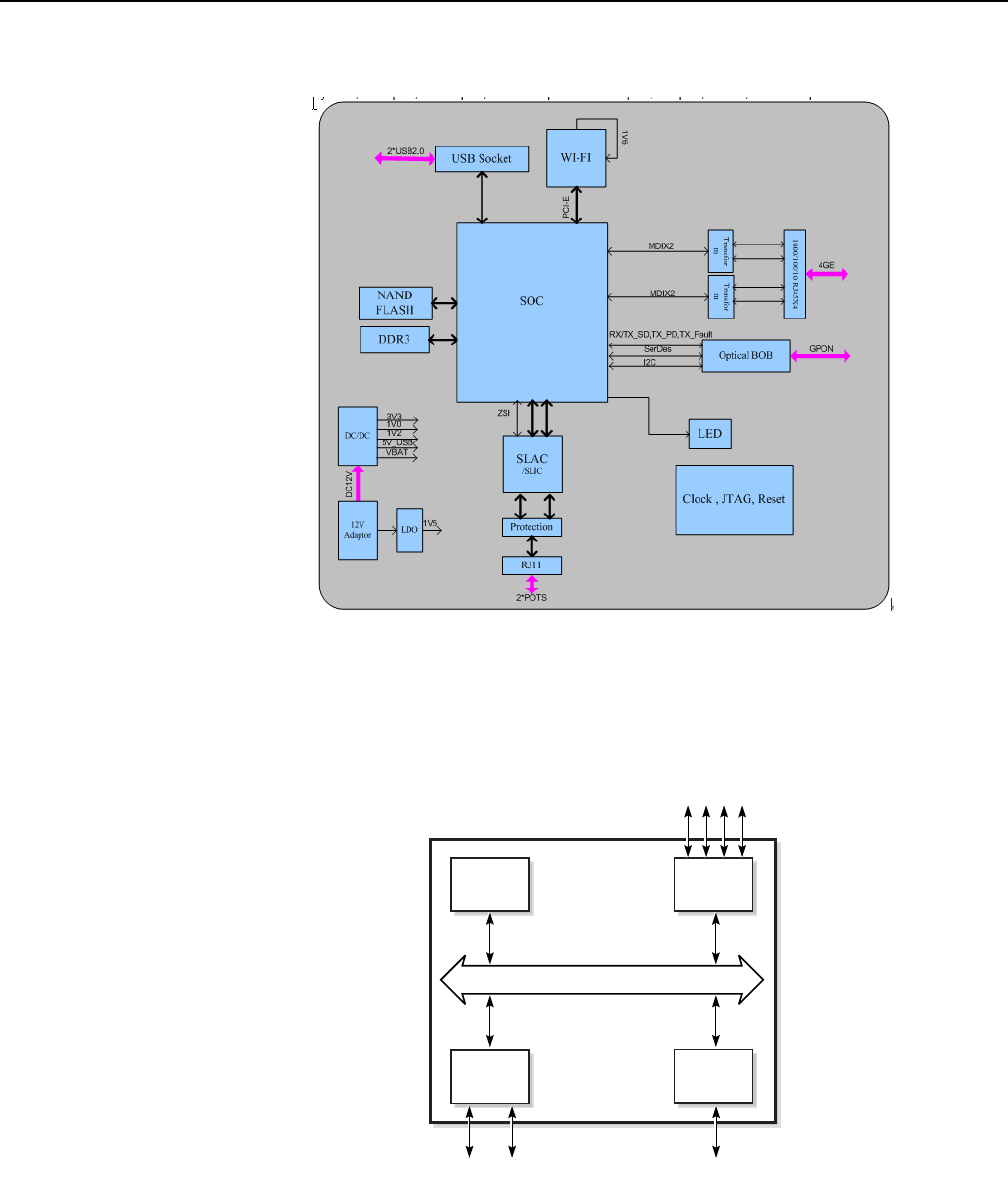
7368 ISAM ONT G-240W-F Product Guide G-240W-F unit data sheet
Issue: 01 Edition 01 61
Figure 18 Single-residence Wi-Fi ONT with Gigabit Ethernet and POTS and
without RF video
ONT SoC technology serves as the main hardware block for these ONTs; see
Figure 19.
Figure 19 G-240W-F ONT hardware block
Control
processor
Ethernet
MACs
Ethernet ports GPON
POTS ports
DSP
GPON
MAC
SoC
19421
SoC Bridge
DRAFT

G-240W-F unit data sheet
62
7368 ISAM ONT G-240W-F Product Guide
Edition 01 Issue: 01
ONT SoC technology consists of five key elements:
•GPON MAC
The Gigabit Passive Optical Network Media Access Control (GPON MAC)
element on the SoC terminates the GPON interface using an optical diplexer. This
interface supports GPON as described in G.984.3 (GPON TC Layer) ITU
specification.
•Ethernet MAC
The SoC provides up to four GE MACs.
•DSP interface
The Digital Signal Processor (DSP) provides voice processing for 2 POTS lines
with 3-way calling. The DSP has a dedicated 64 kbyte instruction cache and
shares a 32 kbyte data cache with the Control Processor. It provides up to 4
network processor cores, each at 800MHz.
•Control Processor
The Control Processor features an integral memory management unit that
supports a dedicated 64 kbyte instruction cache and shares a single 32 kbyte data
cache with the DSP. The Control Processor and DSP also include a single
channel Data Management Application (DMA) controller with a 4 kbyte read
ahead low-latency Dynamic Random Access Memory (DRAM) access port. The
processors typically run at 600 MHz.
•Switch matrix
The Switch matrix provides an integrated data channel between the four GE
MACs, the GPON MAC, the DSP, the control processor, and the other integrated
elements such as flash memory, DRAM, and the local bus controller.
These ONTs can also interact with additional hardware components to support
functionality not provided by the SoC technology.
5.10 G-240W-F standards compliance
G-240W-F indoor ONTs are compliant with the following standards:
•802.1p QoS
•802.1q VLANs
•802.3 auto negotiation, flow control
•802.11 b/g/n at 2.4 GHz
•Codec G.711 a/u, G.722, G.723, G.726, G.729
•EN 300-328 v1.9.1 wide band data transmission standards for 2.4GHz bands
•Energy Star standards. Level 6
•EU CoC v5 broadband communication
•G.984 support GPON interface (framing)
•G.984.2 support for Amd1, class B+
•G.984.3 support for activation and password functions
•G.984.3 support for AES with operator enable/disable on per port-ID level
DRAFT

7368 ISAM ONT G-240W-F Product Guide G-240W-F unit data sheet
Issue: 01 Edition 01 63
•G.984.3 support for FEC in both upstream and downstream directions
•G.984.3 support for multicast using a single GEM Port-ID for all video traffic
•G984.4 and G.983.2 support for OMCI v1 and v2 interface for ONT management
and provisioning
•SIPv2 RFC 3261 signaling
5.10.1 Energy-related products standby and off modes
compliance
Hereby, Nokia declares that the G-240W-F ONTs are in compliance with the
essential requirements and other relevant provisions of Directive 2009/125/EC
together with Commission Regulation (EC) No 1275/2008 and Commission
Regulation (EC) No 801/2013.
The G-240W-F ONTS qualify as equipment with high network availability (HiNA)
functionality. Since the main purpose of G-240W-F ONTs is to provide network
functionality with HiNA 7 days /24 hours, the modes Off/Standby, Power
Management, and Networked Standby are inappropriate.
For information about the type and number of network ports, see “G-240W-F
interfaces and interface capacity” in this chapter.
For information about power consumption, see “G-240W-F detailed specifications” in
this chapter.
5.11 G-240W-F special considerations
G-240W-F is a package P ONT.
5.11.1 Wi-Fi service
G-240W-F indoor ONTs feature Wi-Fi service as well as voice and data services.
Wi-Fi is a wireless networking technology that uses radio waves to provide wireless
HSI and network connections. This ONT complies with the IEEE 802.11 standards,
which the Wi-Fi Alliance defines as the basis for Wi-Fi technology.
DRAFT

G-240W-F unit data sheet
64
7368 ISAM ONT G-240W-F Product Guide
Edition 01 Issue: 01
5.11.1.1 Wi-Fi physical features
G-240W-F indoor ONTs have the following physical features that assist in providing
Wi-Fi service:
•WLAN button for enabling and disabling Wi-Fi service
•two external multi-directional antennae
•Wi-Fi Protected Setup (WPS) push button for enabling and disabling wireless
protective services
5.11.1.2 Wi-Fi standards and certifications
The Wi-Fi service on G-240W-F indoor ONTs supports the following IEEE standards
and Wi-Fi Alliance certifications:
•certified for IEEE 802.11b/g/n standards
•WPA support including WPA-PSK
•certified for WPA2-Personal and WPA2-Enterprise
5.11.1.3 Wi-Fi GUI features
G-240W-F indoor ONTs have HTML-based Wi-Fi configuration GUIs.
5.11.2 G-240W-F ONT considerations and limitations
Table 15 lists the considerations and limitations for Package P G-240W-F ONTs.
Table 15 G-240W-F ONT considerations and limitations
Considerations and limitations
Do not put the metallic material plate on top of the enclosure.
There is a limit of 3 RENs for each POTS line.
Call History Data collection (ONTCALLHST) is supported, except for the following parameters:
RTP packets (discarded), far-end RTCP and RTCP-XR participation, RTCP average and peak round trip delay,
MOS, average jitter, number of jitter-buffer over-runs and under runs.
Some voice features are configurable on a per ONT basis, including Call Waiting, Call Hold, 3-Way Calling, and
Call Transfer.
(1 of 2)
DRAFT

7368 ISAM ONT G-240W-F Product Guide G-240W-F unit data sheet
Issue: 01 Edition 01 65
The following voice features / GSIP parameters are configurable on a per-Client/ per-ONT basis (not
per-Subscriber):
•Enable Caller ID and Enable Caller Name ID
•Digitmap and the associated Interdigit and Critical timers and Enter key parameters
•Warmline timer is enabled per subscriber, but the warmline timer value is configured per ONT and must
have a lower value than the Permanent time
•Miscellaneous timers: Permanent, Timed-release, Reanswer, Error-tone, and CW-alert timers
•Features / functions: Message waiting mode, WMWI refresh interval, DTMF volume level
•Service Codes for the following features: CCW, Call Hold and Warmline
Considerations and limitations
(2 of 2)
DRAFT

G-240W-F unit data sheet
66
7368 ISAM ONT G-240W-F Product Guide
Edition 01 Issue: 01
DRAFT

7368 ISAM ONT G-240W-F Product Guide Install a G-240W-F indoor ONT
Issue: 01 Edition 01 67
6 Install a G-240W-F indoor ONT
6.1 Purpose
6.2 General
6.3 Prerequisites
6.4 Recommended tools
6.5 Safety information
6.6 Procedure
6.1 Purpose
This chapter provides the steps to install a G-240W-F indoor ONT.
6.2 General
The steps listed in this chapter describe mounting and cabling for G-240W-F indoor
ONTs.
6.3 Prerequisites
You need the following items before beginning the installation:
•all required cables
6.4 Recommended tools
You need the following tools for the installation:
•#2 Phillips screwdriver
•1/4 in. (6 mm) flat blade screwdriver
•wire strippers
•fiber optic splicing tools
•RJ-45 cable plug crimp tool
•voltmeter or multimeter
•optical power meter
DRAFT
Install a G-240W-F indoor ONT
68
7368 ISAM ONT G-240W-F Product Guide
Edition 01 Issue: 01
•drill and drill bits
•paper clip
6.5 Safety information
Read the following safety information before installing the unit.
Danger 1 — Hazardous electrical voltages and currents can
cause serious physical harm or death. Always use insulated
tools and follow proper safety precautions when connecting or
disconnecting power circuits.
Danger 2 — Make sure all sources of power are turned off and
have no live voltages present on feed lines or terminals. Use a
voltmeter to measure for voltage before proceeding.
Danger 3 — Always contact the local utility company before
connecting the enclosure to the utilities.
Warning — This equipment is ESD sensitive. Proper ESD
protections should be used when removing the fiber access
cover of the indoor ONT.
Caution — Keep indoor ONTs out of direct sunlight. Prolonged
exposure to direct sunlight can damage the unit.
Note 1 — Observe the local and national laws and regulations
that may be applicable to this installation.
Note 2 — Observe the following:
•The indoor ONT should be installed in accordance with the
applicable requirements of the NEC or CEC. Local
authorities and practices take precedent when there is
conflict between the local standard and the NEC or CEC.
•The indoor ONT must be installed by qualified service
personnel.
•Indoor ONTs must be installed with cables that are suitably
rated and listed for indoor use.
•See the detailed specifications in the G-240W-F unit data
sheet for the temperature ranges for these ONTs.
DRAFT
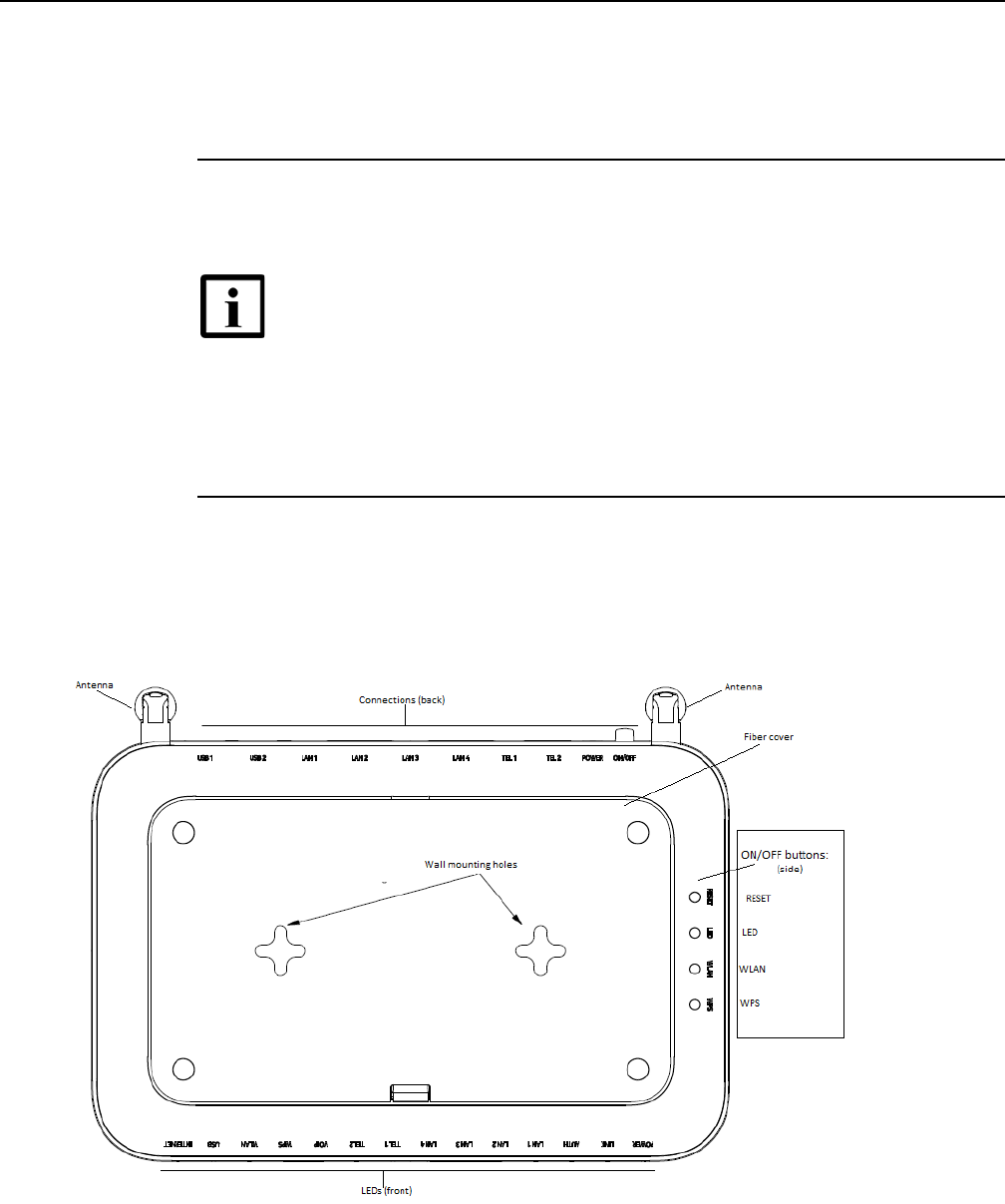
7368 ISAM ONT G-240W-F Product Guide Install a G-240W-F indoor ONT
Issue: 01 Edition 01 69
6.6 Procedure
Use this procedure to install a G-240W-F indoor ONT.
1Place the indoor ONT unit:
aOn the flat surface, such as a desk; go to step 3.
bOn a wall, go to step 2.
2Mount the G-240W-F indoor ONT on a wall.
iThe G-240W-F indoor ONT can be mounted in either a horizontal or vertical position.
Figure 20 shows the wall mounting holes for the G-240W-F ONTs.
Figure 20 G-240W-F indoor ONT wall mounting holes (bottom view)
Note — The G-240W-F cannot be stacked with another ONT or with
other equipment. The ONT mounting requirements are:
•allow a minimum 100 mm clearance above the top cover
•allow a minimum 50 mm clearance from the side vents
•do not place any heat source directly above the top cover or below the
bottom cover
DRAFT
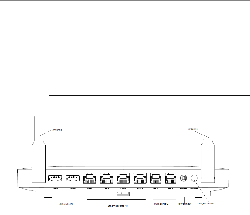
Install a G-240W-F indoor ONT
70
7368 ISAM ONT G-240W-F Product Guide
Edition 01 Issue: 01
If possible, mount the ONT on a wall stud
ii Mark the wall with the location of the mounting holes. These holes should be the same
distance apart as the distance between the centers of the keyholes on the ONT.
iii Drill the two holes in the wall where the ONT will be mounted and then drive the
mounting screws into the holes.
The recommended length of mounting screw is 1.15 in. (3.8 cm).
Do not drive the screw into the wall completely. Leave approximately 1/8 in. (6 mm)
between the screw head and the wall surface.
iv Slide the wall mount keyholes on the ONT enclosure down over the mounting screws
until the ONT is securely seated.
3Review the connection locations as shown in Figures 21 and 22.
Figure 21 G-240W-F indoor ONT connections (back view)
DRAFT
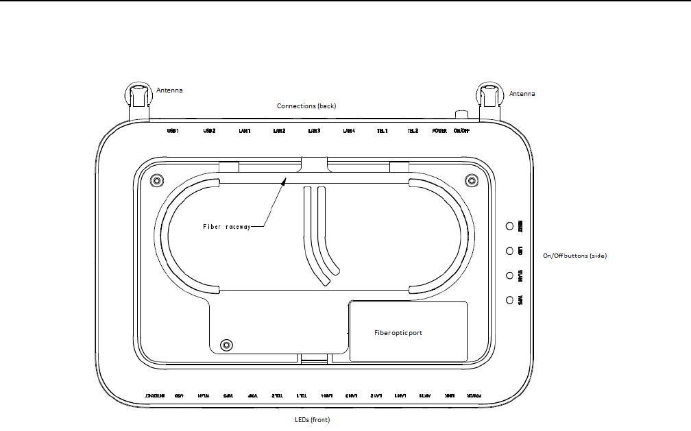
7368 ISAM ONT G-240W-F Product Guide Install a G-240W-F indoor ONT
Issue: 01 Edition 01 71
Figure 22 G-240W-F ONT Reset, LED, WLAN, and WPS buttons and fiber optic connection
(bottom and side view)
The G-240W-F ONT features a fiber cover to protect the fiber optic cable and connection, as
shown in Figure 23.
DRAFT
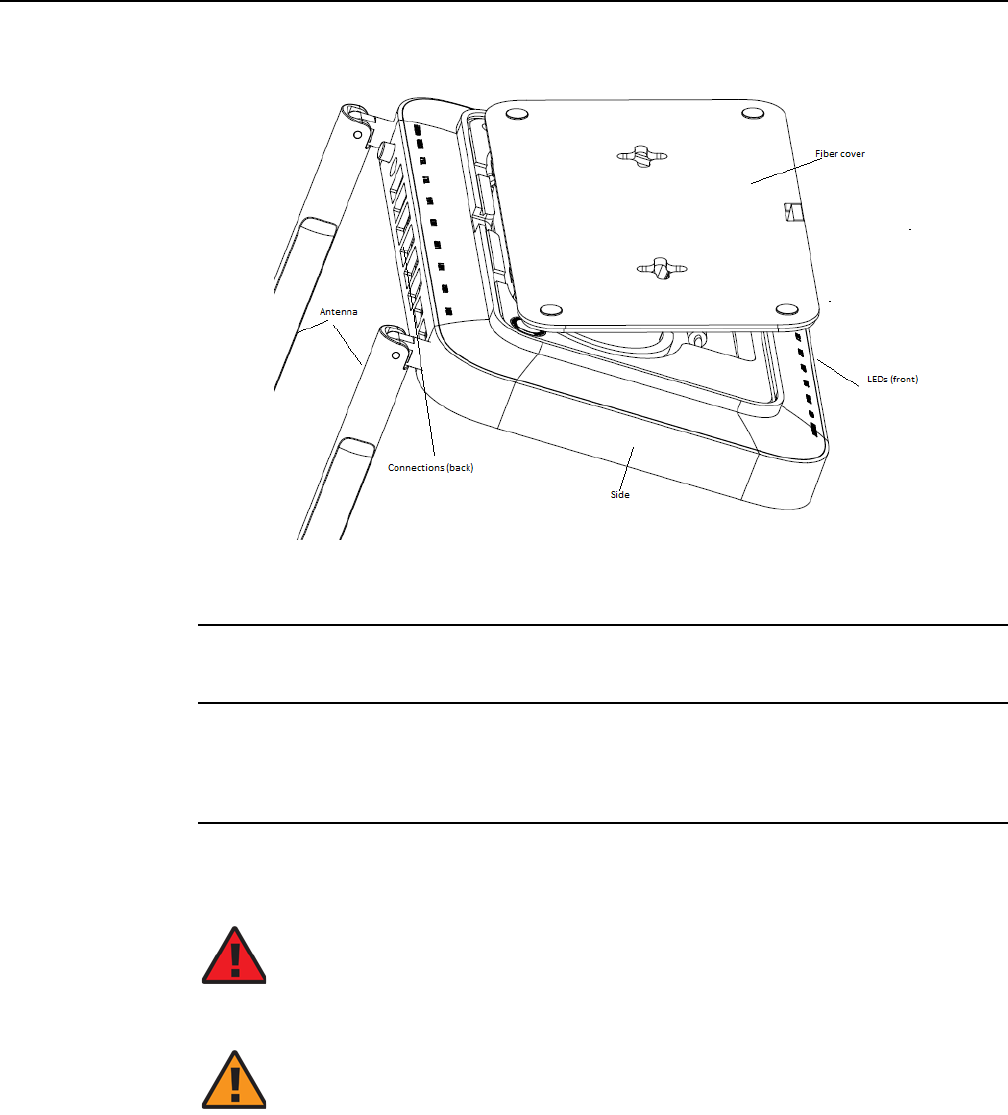
Install a G-240W-F indoor ONT
72
7368 ISAM ONT G-240W-F Product Guide
Edition 01 Issue: 01
Figure 23 G-240W-F indoor ONT with fiber cover open
4Connect the Ethernet cables to the RJ-45 ports; see Figure 21 for the location of the RJ-45
ports.
5Route the POTS cables directly to the RJ-11 ports as per local practices.
The POTS port to the left is labeled 1 for Line 1 while the port on the right is labeled 2 for Line
2, as shown in Figure 21.
6Connect the fiber optic cable with SC/APC adapter into the SC/APC connector on the bottom
of the ONT; see Figure 22 for the location of the SC/APC connector.
Danger — Fiber cables transmit invisible laser light. To avoid eye
damage or blindness, never look directly into fibers, connectors, or
adapters.
Warning — Be careful to maintain a bend radius of no less than 1.5 in.
(3.8 cm) when connecting the fiber optic cable. Too small of a bend radius
in the cable can result in damage to the optic fiber.
DRAFT

7368 ISAM ONT G-240W-F Product Guide Install a G-240W-F indoor ONT
Issue: 01 Edition 01 73
7Install the power supply according to manufacturer specifications.
8Connect the power cable to the power connector.
9Power up the ONT unit by using the power switch.
10 If used, enable the Wi-Fi service.
iLocate the WLAN button on the side of the ONT; see Figure 22 for location of the WLAN
button.
ii Press the WLAN button to change the status of the Wi-Fi service.
11 If used, enable the WPS.
iLocate the WPS button on the side of the ONT; see Figure 22 for location of the WPS
button.
ii Press the WPS button to change the status of the WPS.
12 Verify the ONT LEDs, voltage status, and optical signal levels; see the 7368 Hardware and
Cabling Installation Guide.
13 Activate and test the services; see the 7368 Hardware and Cabling Installation Guide.
14 If used, configure the SLID; see the 7368 ISAM ONT Configuration, Management, and
Troubleshooting Guide.
15 If necessary, reset the ONT.
iLocate the Reset button on the side of the G-240W-F indoor ONT as shown in
Figure 22.
ii Insert the end of a straightened paper clip or other narrow object into the hole in the
Reset button to reset the ONT.
16 STOP. This procedure is complete.
Note — Fiber cable preparation varies depending on the type and size
of the inside or outside plant fiber cable being spliced to the SC/APC
(SC/UPC) fiber optic pigtail cable.
Note — Observe the following:
•Units must be powered by a Listed or CE approved and marked
limited power source power supply with a minimum output rate of
12 V dc, 1.25 A.
DRAFT

Install a G-240W-F indoor ONT
74
7368 ISAM ONT G-240W-F Product Guide
Edition 01 Issue: 01
DRAFT

7368 ISAM ONT G-240W-F Product Guide Replace a G-240W-F indoor ONT
Issue: 01 Edition 01 75
7 Replace a G-240W-F indoor ONT
7.1 Purpose
7.2 General
7.3 Prerequisites
7.4 Recommended tools
7.5 Safety information
7.6 Procedure
7.1 Purpose
This chapter provides the steps to replace G-240W-F indoor ONTs.
7.2 General
The steps listed in this chapter describe mounting and cabling for G-240W-F indoor
ONTs.
7.3 Prerequisites
You need the following items before beginning the installation:
•all required cables
7.4 Recommended tools
You need the following tools for replacing the ONT:
•#2 Phillips screwdriver
•1/4 in. (6 mm) flat blade screwdriver
•wire strippers
•fiber optic splicing tools
•RJ-45 cable plug crimp tool
•voltmeter or multimeter
DRAFT

Replace a G-240W-F indoor ONT
76
7368 ISAM ONT G-240W-F Product Guide
Edition 01 Issue: 01
•optical power meter
•drill and drill bits
7.5 Safety information
Read the following safety information before replacing the unit.
Danger 1 — Hazardous electrical voltages and currents can
cause serious physical harm or death. Always use insulated
tools and follow proper safety precautions when connecting or
disconnecting power circuits.
Danger 2 — Make sure all sources of power are turned off and
have no live voltages present on feed lines or terminals. Use a
voltmeter to measure for voltage before proceeding.
Danger 3 — Always contact the local utility company before
connecting the enclosure to the utilities.
Warning — This equipment is ESD sensitive. Proper ESD
protections should be used when removing the fiber access
cover of the indoor ONT.
Caution — Keep indoor ONTs out of direct sunlight. Prolonged
exposure to direct sunlight can damage the unit.
Note 1 — Observe the local and national laws and regulations
that may be applicable to this installation.
Note 2 — Observe the following:
•The indoor ONT should be installed in accordance with the
applicable requirements of the NEC or CEC. Local
authorities and practices take precedent when there is
conflict between the local standard and the NEC or CEC.
•The indoor ONT must be installed by qualified service
personnel.
•Indoor ONTs must be installed with cables that are suitably
rated and listed for indoor use.
•See the detailed specifications in the G-240W-F unit data
sheet for the ONT temperature ranges for these ONTs.
DRAFT
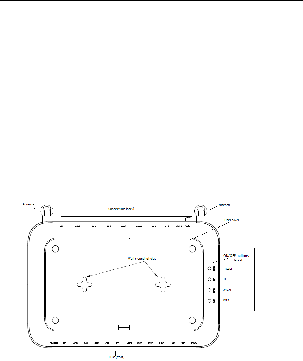
7368 ISAM ONT G-240W-F Product Guide Replace a G-240W-F indoor ONT
Issue: 01 Edition 01 77
7.6 Procedure
Use this procedure to replace a G-240W-F indoor ONT.
1Deactivate the ONT services at the P-OLT.
If you are using the SLID feature, this step is not required. The ONT and the services can
remain in service (IS).
iUse the RTRV-ONT command to verify the ONT status and th associated services.
Record the serial number or the SLID of the ONT displayed in the command output.
Example:
RTRV-ONT::ONT-1-1-1-1-1;
ii If the ONT is in service, place the ONT in OOS state.
Example:
ED-ONT::ONT-1-1-1-1-1;
2If used, disable the Wi-Fi service by pressing the WLAN button; see Figure 24 for the location
of the WLAN button on the side of the ONT.
Figure 24 G-240W-F indoor ONT Reset, LED, WLAN, and WPS buttons (side)
DRAFT
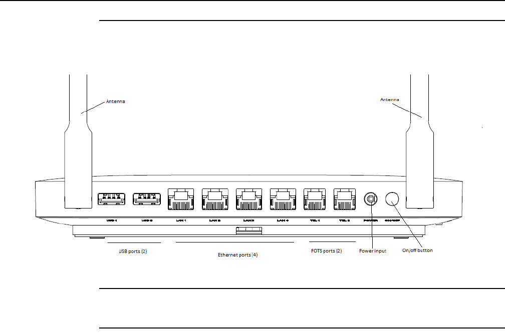
Replace a G-240W-F indoor ONT
78
7368 ISAM ONT G-240W-F Product Guide
Edition 01 Issue: 01
3Power down the unit by using the on/off power switch; see Figure 25 for the location of the
power switch.
Figure 25 G-240W-F indoor ONT connections (back view)
4Disconnect the POTS, Ethernet, and power cables from the ONT; see Figure 25 for the
connector locations on the G-240W-F indoor ONT.
5Disconnect the fiber optic cable; see Figure 26 for the location of the fiber optic port on the
bottom of the ONT..
DRAFT
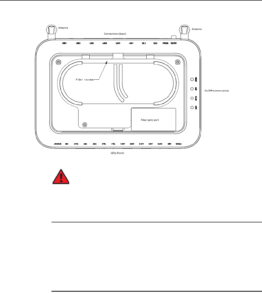
7368 ISAM ONT G-240W-F Product Guide Replace a G-240W-F indoor ONT
Issue: 01 Edition 01 79
Figure 26 G-240W-F indoor ONT fiber optic port (bottom view)
iUnplug the fiber optic cable with SC/APC connector from the fiber optic port on the
bottom of the ONT; see Figure 26 for the location of the fiber optic port.
ii Attach a fiber dust cover to the end of the SC/APC (SC/UPC) connector.
6Replace the ONT with a new unit:
aOn a flat surface, such as a desk, substitute the new ONT for the old ONT on a flat
surface, horizontally resting on its four feet.
bOn a wall.
iSlide the old ONT off of the mounting screws until the ONT is free of the wall.
ii Slide the wall mount holes on the ONT enclosure over the mounting screws until
it is securely seated.
7Connect the Ethernet cables directly to the RJ-45 ports; see Figure 25 for the location of the
RJ-45 ports.
Danger — Fiber cables transmit invisible laser light. To avoid eye
damage or blindness, never look directly into fibers, connectors, or
adapters.
DRAFT
Replace a G-240W-F indoor ONT
80
7368 ISAM ONT G-240W-F Product Guide
Edition 01 Issue: 01
8Connect the POTS cables directly to the RJ-11 ports as per local practices; see Figure 25 for
the location of the RJ-11 ports.
The RJ-11 port to the left is labeled 1 for Line 1 while the port on the right is labeled 2 for Line
2.
9If required, have approved service personnel who are trained to work with optic fiber clean
the fiber optic connection. See the 7368 ISAM ONT Configuration, Management, and
Troubleshooting Guide for more information about fiber optic handling, inspection, and
cleaning.
10 Connect the fiber optic cable with SC/APC adapter into the SC/APC connector on the bottom
of the ONT. Figure 26 shows the location of the SC/APC connector.
11 Install the power supply according to manufacturer specifications.
12 Connect the power cable to the power connector.
13 Power up the unit by using the power switch.
14 If used, enable the Wi-Fi service by pressing the WLAN button on the side of the ONT; see
Figure 24 for the location of the WLAN button.
15 If used, enable the WPS by pressing the WPS button on the side of the ONT; see Figure 24
for the location of the WPS button.
Danger — Fiber cables transmit invisible laser light. To avoid eye
damage or blindness, never look directly into fibers, connectors, or
adapters.
Warning — Be careful to maintain a bend radius of no less than 1.5 in.
(3.8 cm) when connecting the fiber optic cable. Too small of a bend radius
in the cable can result in damage to the optic fiber.
Note — Fiber cable preparation varies depending on the type and size
of the inside or outside plant fiber cable being spliced to the SC/APC fiber
optic pigtail cable.
Note — Observe the following:
•Units must be powered by a Listed or CE approved and marked
limited power source power supply with a minimum output rate of
12 V dc, 1.25 A.
DRAFT

7368 ISAM ONT G-240W-F Product Guide Replace a G-240W-F indoor ONT
Issue: 01 Edition 01 81
16 If used, configure the SLID; see the 7368 ISAM ONT Configuration, Management, and
Troubleshooting Guide for more information.
17 Verify the ONT LEDs, voltage status, and optical signal levels; see the 7368 Hardware and
Cabling Installation Guide.
18 Activate and test the services; see the 7368 Hardware and Cabling Installation Guide.
19 If necessary, reset the ONT.
iLocate the Reset button on the side of the G-240W-F indoor ONT as shown in
Figure 24.
ii Insert the end of a straightened paper clip or other narrow object into the hole in the
Reset button to reset the ONT.
20 STOP. This procedure is complete.
Note — A new SLID or the old SLID may be used with the replacement
ONT. If a new SLID is used, the new SLID must also be programmed at
the P-OLT using TL1 or a network manager. If the old SLID is used, no
changes need to be made at the P-OLT; see the operations and
maintenance documentation for the OLT for more details.
DRAFT

Replace a G-240W-F indoor ONT
82
7368 ISAM ONT G-240W-F Product Guide
Edition 01 Issue: 01
DRAFT

7368 ISAM ONT G-240W-F Product Guide Configure a G-240W-F indoor ONT
Issue: 01 Edition 01 83
8 Configure a G-240W-F indoor ONT
8.1 General
8.2 HGU mode GUI configuration
8.3 SFU mode GUI configuration
8.4 Operator ID
8.1 General
Please refer to the configuration information provided with your OLT for the software
configuration procedure for a G-240W-F ONT.
For HTTP configuration procedures, please refer to the 7368 ISAM ONT
Configuration, Management, and Troubleshooting Guide.
8.2 HGU mode GUI configuration
Use the procedures below to utilize the web-based GUI for the G-240W-F in HGU
mode. This mode is preset at delivery.
A home gateway unit (HGU) is a home networking device, used as a gateway to
connect devices in the home through fiber to the Internet. An HGU provides a variety
of features for the home network including routing and firewall capability. By using
the HGU, users can connect all smart equipment in their home, including personal
computers, set-top boxes, mobile phones, and other consumer electronics devices,
to the Internet.
8.2.1 Login
Use the procedure below to login to the web-based GUI for the G-240W-F.
Procedure 6 Login to web-based GUI
1Open a web browser and enter the IP address of the ONT in the address bar.
The login window appears.
DRAFT
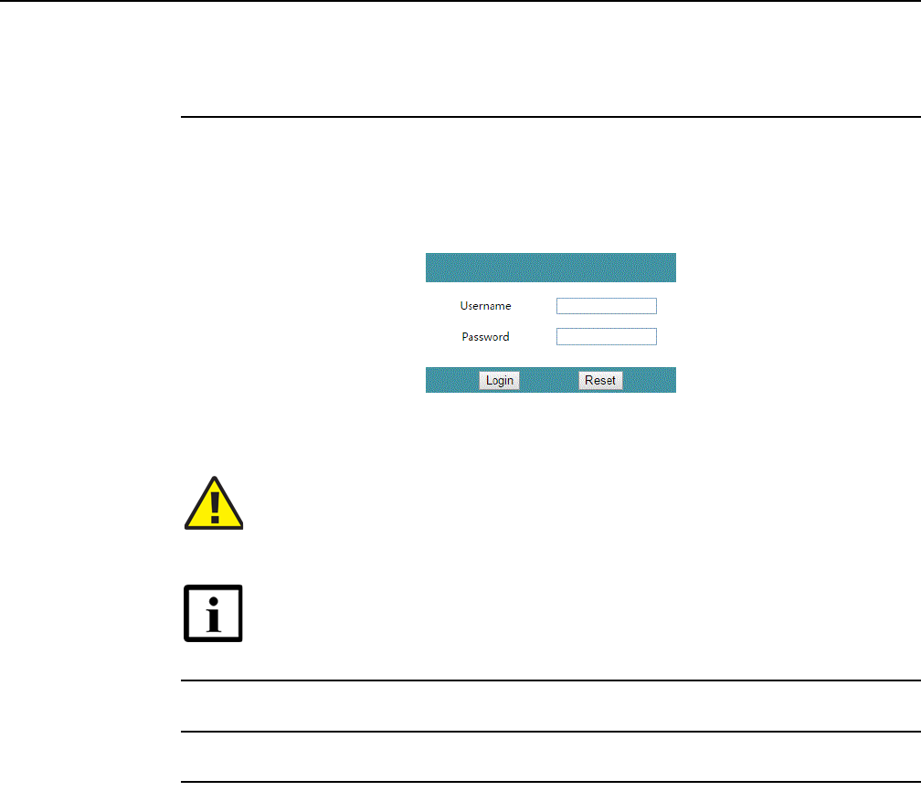
Configure a G-240W-F indoor ONT
84
7368 ISAM ONT G-240W-F Product Guide
Edition 01 Issue: 01
The default gateway IP address is http://192.168.1.254. You can connect to this IP address
using your web browser after connecting your PC to one of Ethernet ports of the ONT. The
static IP address of your PC must be in the same subnet as the ONT.
2Enter your username and password in the Log in window, as shown in Figure 27.
The default user name is userAdmin. The default password is a random number, which is
included in the ONT kit.
Figure 27 Web login window
3Click Login.
4STOP. This procedure is complete.
8.2.2 Device and connection status
G-240W-F ONTs support the retrieval of a variety of device and connection
information, including:
•device information
•LAN status
•WAN status
•WAN status IPv6
•Home networking information
Caution — Pressing the Reset button for less than 10 seconds reboots
the ONT; pressing the Reset button for 10 seconds resets the ONT to the
factory defaults, except for the LOID and SLID.
Note — If you forget the current username and password, press the
reset button for 10 s and the default values for the username and
password will be recovered at startup.
DRAFT
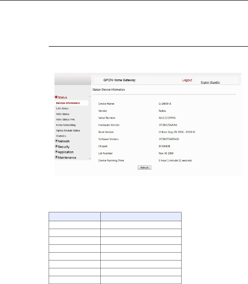
7368 ISAM ONT G-240W-F Product Guide Configure a G-240W-F indoor ONT
Issue: 01 Edition 01 85
•Optics module status
•Voice information
Procedure 7 Device information retrieval
1Select Status > Device Information from the top-level menu in the GPON Home Gateway
window, as shown in Figure 28.
Figure 28 Device Information window
Table 16 describes the fields in the Device Information window.
Table 16 Device Information parameters
Field Description
Device Name Name on the ONT
Vendor Name of the vendor
Serial Number Serial number of the ONT
Hardware version Hardware version of the ONT
Boot version Boot version of the ONT
Software version Software version of the ONT
Chipset Chipset of the ONT
Lot Number Production date of the ONT
(1 of 2)
DRAFT
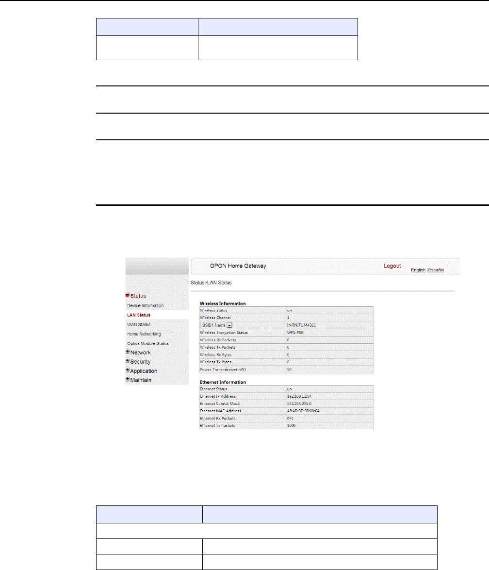
Configure a G-240W-F indoor ONT
86
7368 ISAM ONT G-240W-F Product Guide
Edition 01 Issue: 01
2Click Refresh to update the displayed information.
3STOP. This procedure is complete.
Procedure 8 LAN status retrieval
1Select Status > LAN Status from the top-level menu in the GPON Home Gateway window,
as shown in Figure 29.
Figure 29 LAN status window
Table 17 describes the fields in the LAN status window.
Table 17 LAN status parameters
Device Running Time Amount of time the device has run since
last reset in hours, minutes, and seconds
Field Description
(2 of 2)
Field Description
Wireless Information
Wireless Status Indicates whether the wireless is on or off
Wireless Channel Wireless channel number
(1 of 2)
DRAFT

7368 ISAM ONT G-240W-F Product Guide Configure a G-240W-F indoor ONT
Issue: 01 Edition 01 87
2Click Refresh to update the displayed information.
3STOP. This procedure is complete.
SSID Name Name of each SSID
Wireless Encryption Status Encryption type used on the wireless connection
Wireless Rx Packets Number of packets received on the wireless connection
Wireless Tx Packets Number of packets transmitted on the wireless connection
Wireless Rx Bytes Number of bytes received on the wireless connection
Wireless Tx Bytes Number of bytes transmitted on the wireless connection
Power Transmission (mW) Power of the wireless transmission, in mW
Ethernet Information
Ethernet Status Indicates whether the Ethernet connection is on or off
Ethernet IP Address IP address of the Ethernet connection
Ethernet Subnet Mask Subnet Mask of the Ethernet connection
Ethernet MAC Address MAC address of the Ethernet connection
Ethernet Rx Packets Number of packets received on the Ethernet connection
Ethernet Tx Packets Number of packets transmitted on the Ethernet connection
Ethernet Rx Bytes Number of bytes received on the Ethernet connection
Ethernet Tx Bytes Number of bytes transmitted on the Ethernet connection
Field Description
(2 of 2)
DRAFT
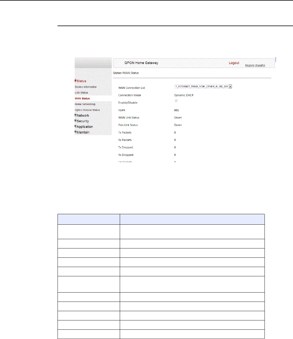
Configure a G-240W-F indoor ONT
88
7368 ISAM ONT G-240W-F Product Guide
Edition 01 Issue: 01
Procedure 9 WAN status retrieval
1Select Status > WAN Status from the top-level menu in the GPON Home Gateway window,
as shown in Figure 30.
Figure 30 WAN status window
Table 18 describes the fields in the WAN status window.
Table 18 WAN status parameters
Field Description
WAN connection list Drop-down menu listing all WAN connections. The connection
shown is the connection for which WAN status will be shown.
Connection Mode Connection mode of the WAN connection
Enable/Disable Select this checkbox to enable the WAN connection
VLAN VLAN ID
WAN Link Status Whether the WAN link is up or down
PPPoE Concentrator Displays the PPPoE Access Concentrator (AC) name
This field applies only if the Connection Mode is set to PPPoE
Pon Link Status Whether the PON link is up or down
Tx Packets Number of packets transmitted on the WAN connection
Rx Packets Number of packets received on the WAN connection
Tx Dropped Number of packets dropped on the transmit WAN connection
Rx Dropped Number of packets dropped on the receive WAN connection
(1 of 2)
DRAFT
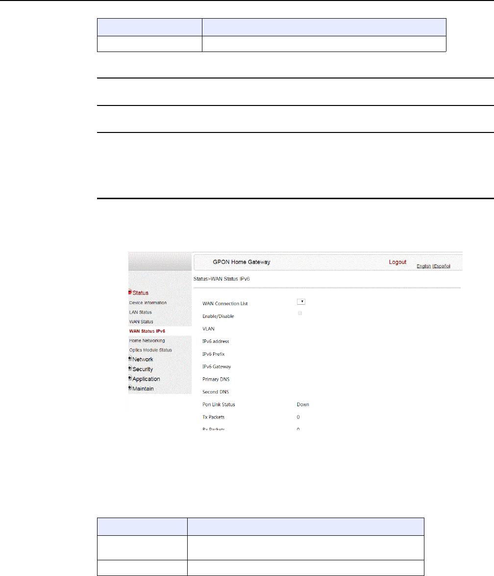
7368 ISAM ONT G-240W-F Product Guide Configure a G-240W-F indoor ONT
Issue: 01 Edition 01 89
2Click Refresh to update the displayed information.
3STOP. This procedure is complete.
Procedure 10 WAN status IPv6 retrieval
1Select Status > WAN Status IPv6 from the top-level menu in the GPON Home Gateway
window, as shown in Figure 31.
Figure 31 WAN status IPv6 window
Table 19 describes the fields in the WAN status IPv6 window.
Table 19 WAN status IPv6 parameters
Err Packets Number of errored packets on the WAN connection
Field Description
(2 of 2)
Field Description
WAN connection list Drop-down menu listing all WAN connections. The connection
shown is the connection for which WAN status will be shown.
Enable/Disable Select this checkbox to enable the WAN connection
(1 of 2)
DRAFT
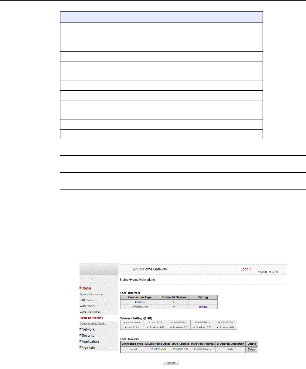
Configure a G-240W-F indoor ONT
90
7368 ISAM ONT G-240W-F Product Guide
Edition 01 Issue: 01
2Click Refresh to update the displayed information.
3STOP. This procedure is complete.
Procedure 11 Home networking information retrieval
1Select Status > Home Networking from the top-level menu in the GPON Home Gateway
window, as shown in Figure 32.
Figure 32 Home networking information window
VLAN VLAN ID
IPv6 Address IPv6 Address that identifies the device and its location
IPv6 Prefix IPv6 prefix
IPv6 Gateway IPv6 gateway address
Primary DNS Primary Domain Name Server
Second DNS Secondary Domain Name Server
Pon Link Status Whether the PON link is up or down
Tx Packets Number of packets transmitted on the WAN connection
Rx Packets Number of packets received on the WAN connection
Tx Dropped Number of packets dropped on the transmit WAN connection
Rx Dropped Number of packets dropped on the receive WAN connection
Err Packets Number of errored packets on the WAN connection
Field Description
(2 of 2)
DRAFT
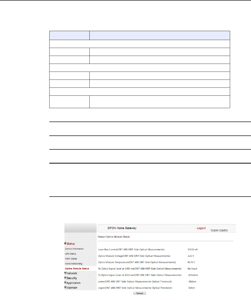
7368 ISAM ONT G-240W-F Product Guide Configure a G-240W-F indoor ONT
Issue: 01 Edition 01 91
Table 20 describes the fields in the Home networking window.
Table 20 Home networking parameters
2Click Delete to delete a particular local device connection.
3Click Refresh to update the displayed information.
4STOP. This procedure is complete.
Procedure 12 Optics module status retrieval
1Select Status > Optics Module Status from the top-level menu in the GPON Home Gateway
window, as shown in Figure 33.
Figure 33 Optics module status window
Field Description
Local Interface
Ethernet Table displays the number of Ethernet connections and their settings
Wireless (2.4G) Table displays the number of wireless connections and their settings
Wireless Settings (2.4G)
Network Name Name of the wireless network
Access Point Hexadecimal address of the wireless access point
Local Devices
Table entry Each entry indicates the connection type, device name, IPv4 address,
hardware address, and IP address allocation of each connected local device.
DRAFT

Configure a G-240W-F indoor ONT
92
7368 ISAM ONT G-240W-F Product Guide
Edition 01 Issue: 01
Table 21 describes the fields in the Optics module status window.
Table 21 Optics module status parameters
2Click Refresh to update the displayed information.
3STOP. This procedure is complete.
Field Description
Laser Bias Current (ONT ANI-ONT-Side Optical
Measurements)
Laser bias current, measured in uA
Optics Module Voltage (ONT ANI-ONT-Side Optical
Measurements)
Optics module voltage, measured in V
Optics Module Temperature (ONT ANI-ONT-Side
Optical Measurements)
Optics module temperature, measured in C
Rx Optics Signal Level at 1490 nm (ONT
ANI-ONT-Side Optical Measurements)
Received optics signal level at 1490 nm, measured
in dBm
Tx Optics Signal Level at 1310 nm (ONT
ANI-ONT-Side Optical Measurements)
Transmitted optics signal level at 1310 nm,
measured in dBm
Lower (ONT ANI-ONT-Side Optical
Measurements-Optical Threshold)
Lower optical threshold, measured in dBm
Upper (ONT ANI-ONT-Side Optical
Measurements-Optical Threshold)
Lower optical threshold, measured in dBm
DRAFT
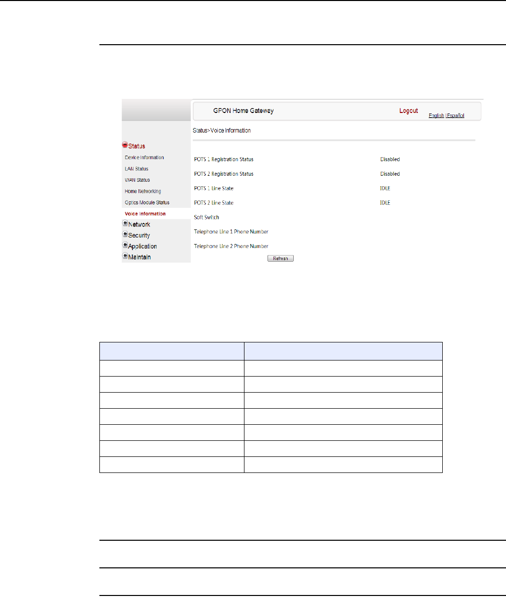
7368 ISAM ONT G-240W-F Product Guide Configure a G-240W-F indoor ONT
Issue: 01 Edition 01 93
Procedure 13 Voice information retrieval
1Select Status > Voice Information from the top-level menu in the GPON Home Gateway
window, as shown in Figure 34.
Figure 34 Voice Information window
Table 22 describes the fields in the Voice Information window.
Table 22 Voice Information parameters
Note
(1) This field is only visible at the adminGPON level; it is not visible at the userAdmin level.
2Click Refresh to update the displayed information.
3STOP. This procedure is complete.
Field Description
POTS 1 Registration Status Status of POTS port 1: registered or unregistered
POTS 2 Registration Status Status of POTS port 2: registered or unregistered
POTS 1 Line State State of POTS line 1: IDLE, Off Hook, or On Hook
POTS 2 Line State State of POTS line 2: IDLE, Off Hook, or On Hook
Softswitch(1) Proxy IP address; blank if the line is not registered
Telephone line 1 phone number(1) Phone number configured for telephone line 1
Telephone line 2 phone number(1) Phone number configured for telephone line 2
DRAFT

Configure a G-240W-F indoor ONT
94
7368 ISAM ONT G-240W-F Product Guide
Edition 01 Issue: 01
8.2.3 Network configuration
G-240W-F ONTs also support network configuration, including:
•LAN
•LAN IPv6
•WAN
•WiFi
•Wireless schedule
•Routing
•DNS
•TR-069
•GRE tunnel
•QoS
•US (upstream) classification
DRAFT
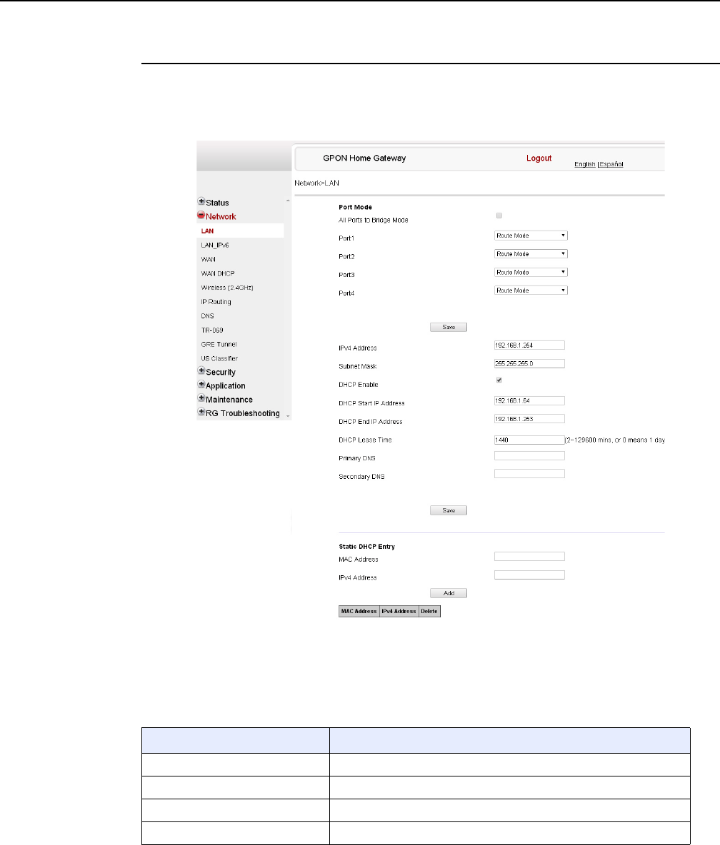
7368 ISAM ONT G-240W-F Product Guide Configure a G-240W-F indoor ONT
Issue: 01 Edition 01 95
Procedure 14 LAN networking configuration
1Select Network > LAN from the top-level menu in the GPON Home Gateway window, as
shown in Figure 35.
Figure 35 LAN network window
Table 23 describes the fields in the LAN network window.
Table 23 LAN network parameters
Field Description
Port Mode: All Port to L2 Mode Select this checkbox to set all ports to L2 mode
Port Mode: Port 1 - 4 Drop-down port mode for each port: Route mode or bridge mode
IPv4 Address IP Address of the ONT
Subnet Mask Subnet mask of the ONT
(1 of 2)
DRAFT

Configure a G-240W-F indoor ONT
96
7368 ISAM ONT G-240W-F Product Guide
Edition 01 Issue: 01
2Select the mode for each port.
3Click Save.
4Enter the DHCP configuration information.
5Click Save.
6Bind a MAC address to the LAN by entering the MAC and IP addresses and then clicking
Add. Repeat for all MAC addresses to be bound.
7STOP. This procedure is complete.
DHCP enable Select this checkbox to enable DHCP
DHCP Start IP Address Starting DHCP IP address
DHCP End IP Address Ending DHCP IP address
DHCP Lease Time DHCP lease time (in min)
Bind MAC Address MAC address to associate to the LAN
Bind IP Address IP address to associate to the bound MAC address
Field Description
(2 of 2)
DRAFT
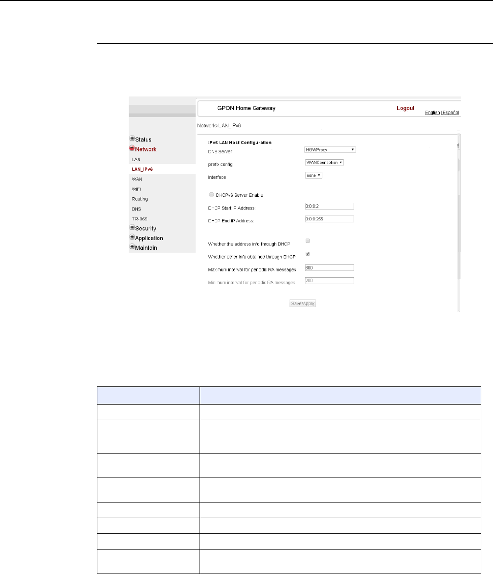
7368 ISAM ONT G-240W-F Product Guide Configure a G-240W-F indoor ONT
Issue: 01 Edition 01 97
Procedure 15 LAN IPv6 networking configuration
1Select Network > LAN_IPv6 from the top-level menu in the GPON Home Gateway window,
as shown in Figure 36.
Figure 36 LAN IPv6 network window
Table 24 describes the fields in the LAN IPv6 network window.
Table 24 LAN IPv6 network parameters
Field Description
DNS Server Choose a DNS server from the drop-down menu.
prefix config Choose a prefix config option from the drop-down menu, either
WANConnection (prefix will be obtained from the WAN) or Static (enables you
to enter the prefix).
prefix This field appears if you selected the “Static” option for the “prefix config” field.
Type a connection.
Interface This field appears if you selected the Wan Connection option for the “prefix
config” field. Choose a WAN connection interface from the drop-down menu.
DHCPv6 Server Enable Select this checkbox to enable DHCP IPv6 server.
DHCP Start IP Address Enter the starting DHCP IP address.
DHCP End IP Address Enter the ending DHCP IP address.
Whether the address info
through DCHP
Select this checkbox to enable address information retrieval through DHCP.
(1 of 2)
DRAFT
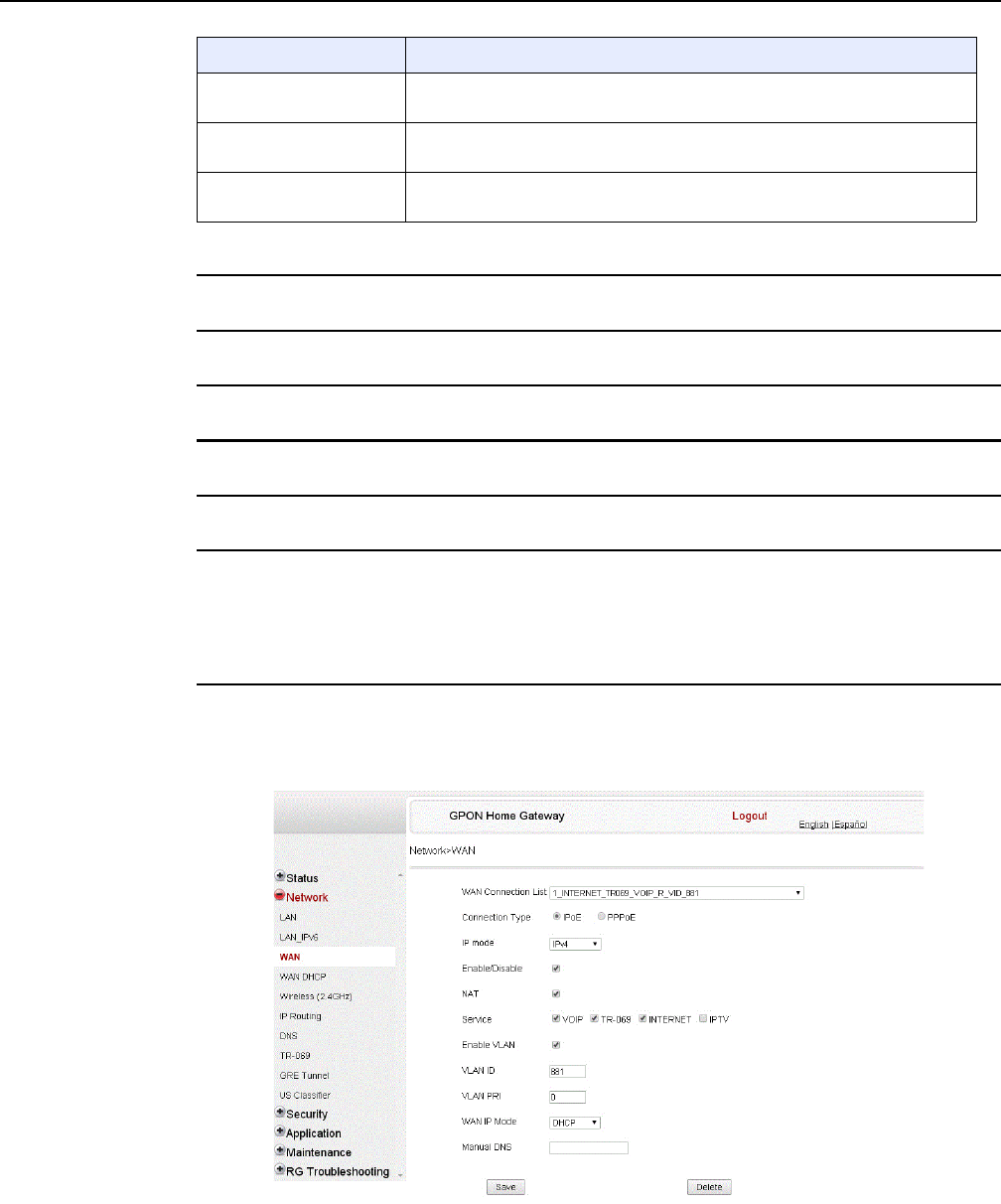
Configure a G-240W-F indoor ONT
98
7368 ISAM ONT G-240W-F Product Guide
Edition 01 Issue: 01
2Choose a DNS server, prefix config, and interface.
3Select or enter the DHCP configuration information.
4Enter the maximum and minimum intervals for RA messages.
5Click Save/Apply.
6STOP. This procedure is complete.
Procedure 16 WAN networking configuration
1Select Network > WAN from the top-level menu in the GPON Home Gateway window, as
shown in Figure 37.
Figure 37 WAN network window
Whether other info
obtained through DHCP
Select this checkbox to enable retrieval of other information through DHCP.
Maximum interval for
periodic RA messages
Enter the maximum interval (in seconds) for periodic Router Advertisement
messages. The interval range is from 4 to 1800.
Minimum interval for
periodic RA messages
Enter the minimum interval (in seconds) for periodic Router Advertisement
messages. The interval range is from 4 to 1800.
Field Description
(2 of 2)
DRAFT

7368 ISAM ONT G-240W-F Product Guide Configure a G-240W-F indoor ONT
Issue: 01 Edition 01 99
Table 25 describes the fields in the WAN network window.
Table 25 WAN network parameters
2Configure a specific WAN connection.
3Click Save.
4STOP. This procedure is complete.
Field Description
WAN Connection List Choose a WAN connection from the drop-down menu to set the connection
parameters
Connection Type Select a connection type: IPoE or PPPoE
IP Mode Choose an IP mode from the drop-down menu: IPv4 or IPv6
Enable/Disable Select this checkbox to enable the WAN connection
NAT Select this checkbox to enable NAT
Service Select the checkboxes to enable service types for this connection
Enable VLAN Select this checkbox to enable VLAN
VLAN ID Enter the VLAN ID
VLAN PRI Enter the VLAN PRI
WAN IP Mode Choose an IP mode from the drop-down menu
Connection Trigger Choose a connection type from the drop-down menu
Username Enter the username
Password Enter the password
Keep Alive Time Enter the Keep Alive Time (from 5 to 60 seconds)
DRAFT
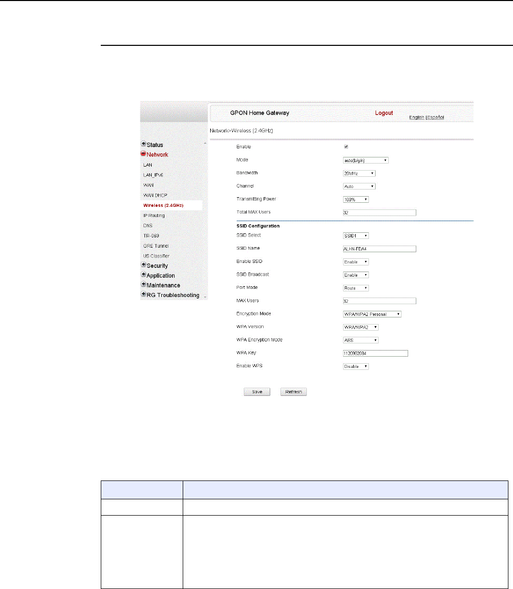
Configure a G-240W-F indoor ONT
100
7368 ISAM ONT G-240W-F Product Guide
Edition 01 Issue: 01
Procedure 17 WiFi networking configuration
1Select Network > WiFi from the top-level menu in the GPON Home Gateway window, as
shown in Figure 38.
Figure 38 WiFi network window
Table 26 describes the fields in the WiFi network window.
Table 26 WiFi network parameters
Field Description
Enable Select this checkbox to enable WiFi
Mode Choose a wi-fi mode from the drop-down menu:
•auto (b/g/n)
•b
•g
•n
•b/g
(1 of 2)
DRAFT

7368 ISAM ONT G-240W-F Product Guide Configure a G-240W-F indoor ONT
Issue: 01 Edition 01 101
Notes
(1) When Encryption Mode is set to “WPA/WPA2 Enterprise”, the following options are no longer available: WPA
version, WPA encryption mode, WPA key, Enable WPS, WPS mode.
(2) When Encryption Mode is set to “WPA/WPA2 Enterprise”, the following options become available: Primary
RADIUS server, port and password; Secondary RADIUS server, port, and password; RADIUS accounting port.
2Configure the WiFi connection.
3If you have enabled and configured WPS, click WPS connect.
Bandwidth Choose a channel from the drop-down menu or choose Auto to have the channel
automatically assigned
Channel Choose a bandwidth option from the drop-down menu
Transmitting Power Choose the percentage transmitting power from the drop-down menu
SSID Select Choose the SSID from the drop-down menu
SSID Name Enter the SSID name
Enable SSID Enable or disable SSID from this drop-down menu
SSID Broadcast Enable or disable SSID broadcast from this drop-down menu
Port Mode Choose a port mode from the drop-down menu:
•Route
•Bridge
Encrypt Mode Choose an encryption mode from the drop-down menu:
•OPEN
•WEP
•WPA/WPA2 Personal
•WPA/WPA2 Enterprise (1)(2)
WPA Version Choose a WPA version from the drop-down menu:
•WPA1
•WPA2
•WPA1/WPA2
WPA Encryption
Mode
Choose a WPA encryption mode from the drop-down menu:
•TKIP
•AES
•TKIP/AES
WPA Key Enter the WPA key
Enable WPS Enable or disable WPS from this drop-down menu
WPS Mode Choose a WPS mode from the drop-down menu:
•PBC
•PIN
PIN Code Number Enter the WPS PIN
Field Description
(2 of 2)
DRAFT
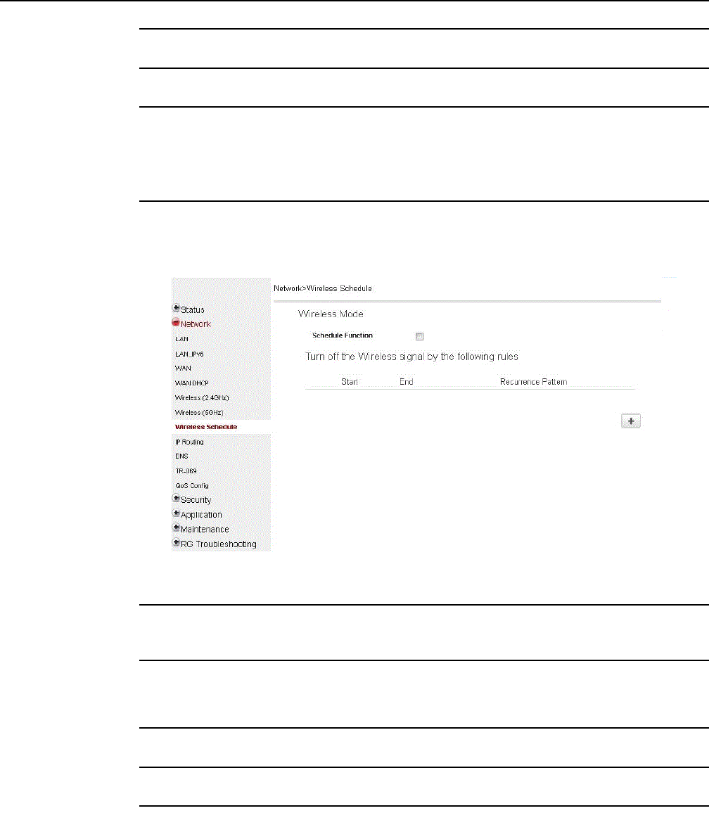
Configure a G-240W-F indoor ONT
102
7368 ISAM ONT G-240W-F Product Guide
Edition 01 Issue: 01
4Click Save.
5STOP. This procedure is complete.
Procedure 18 Wireless scheduling
1Select Network > Wireless Schedule from the top-level menu in the GPON Gateway window,
as shown in Figure 39.
Figure 39 Wireless Schedule window
2Select the Schedule Function checkbox to turn the wireless signal off for the configured
period.
3Click the plus sign (+) to add a scheduling rule.
A separate panel displays for configuring wireless schedule rules.
4Enter a start time and end time for the period in which you want the wireless signal off.
5Choose Everyday or Individual Days from the drop-down menu.
6If you chose Individual Days, select the checkboxes for the desired days.
The Recurrence Pattern shows the rules created to date.
DRAFT
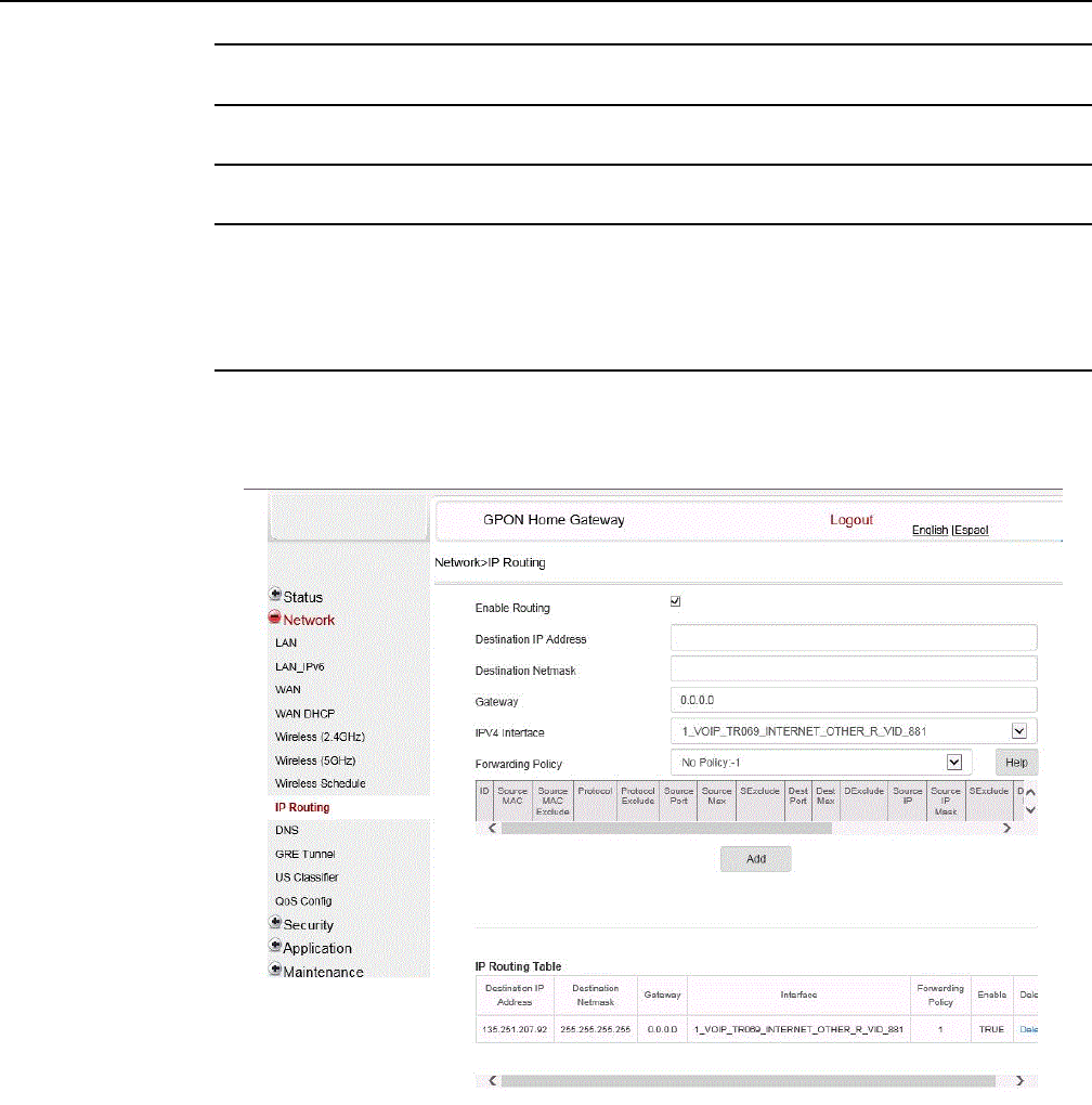
7368 ISAM ONT G-240W-F Product Guide Configure a G-240W-F indoor ONT
Issue: 01 Edition 01 103
7If desired, click the plus sign (+) to add more rules.
8Click Save Changes.
9STOP. This procedure is complete.
Procedure 19 Routing configuration
1Select Network > Routing from the top-level menu in the GPON Home Gateway window, as
shown in Figure 40.
Figure 40 Routing network window
Table 27 describes the fields in the Routing network window.
DRAFT

Configure a G-240W-F indoor ONT
104
7368 ISAM ONT G-240W-F Product Guide
Edition 01 Issue: 01
Table 27 Routing network parameters
2Enter the routing information.
3Click Add.
4STOP. This procedure is complete.
Field Description
Enable Routing Select this checkbox to enable routing
Destination IP Address Enter the destination IP address
Destination Netmask Enter the destination network mask
Gateway Enter the gateway address
IPv4 Interface Choose a WAN connection previously created in the
WAN network window from the drop-down menu
Forwarding Policy Choose a forwarding policy from the drop-down menu
DRAFT
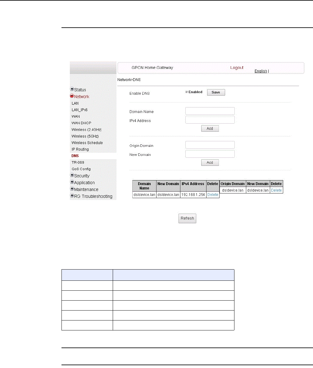
7368 ISAM ONT G-240W-F Product Guide Configure a G-240W-F indoor ONT
Issue: 01 Edition 01 105
Procedure 20 DNS configuration
1Select Network > DNS from the top-level menu in the Home Gateway window, as shown in
Figure 41.
Figure 41 DNS network window
Table 28 describes the fields in the DNS network window.
Table 28 DNS network parameters
2Select the Enabled checkbox and click Save to enable DNS proxy.
3Enter the domain name and IPv4 address and click Add.
Field Description
Enable DNS Select the Enabled checkbox to enable DNS proxy
Domain Name Enter the domain name
IPv4 Address Enter the IPv4 address
OriginalDomain Enter the original domain name
New Domain Enter the new domain name
DRAFT
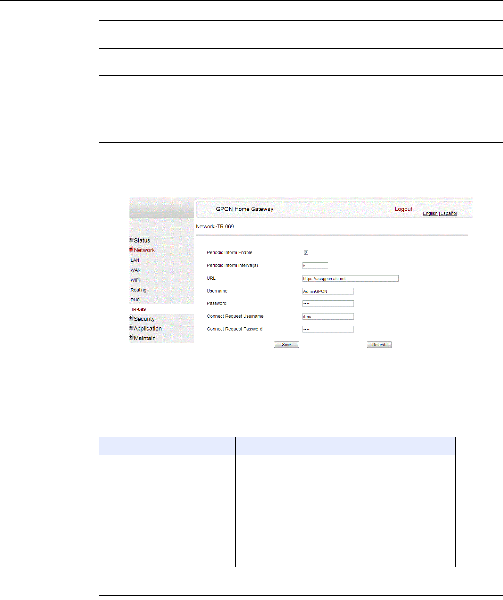
Configure a G-240W-F indoor ONT
106
7368 ISAM ONT G-240W-F Product Guide
Edition 01 Issue: 01
4If required, associate an original domain with a new domain, click Add.
5STOP. This procedure is complete.
Procedure 21 TR-069 configuration
1Select Network > TR-069 from the top-level menu in the GPON Home Gateway window, as
shown in Figure 42.
Figure 42 TR-069 network window
Table 29 describes the fields in the TR-069 network window.
Table 29 TR-069 network parameters
2Configure TR-069 by entering the required information.
Field Description
Periodic Inform Enable Select this checkbox to enable periodic inform updates
Periodic Inform Interval(s) Time between periodic inform updates, in seconds
URL URL of the auto-configuration server
Username Username used to log in to the ONT
Password Password used to log in to the ONT
Connect Request Username Username used to log in to the auto-configuration server
Connect Request Password Password used to log in to the auto-configuration server
DRAFT
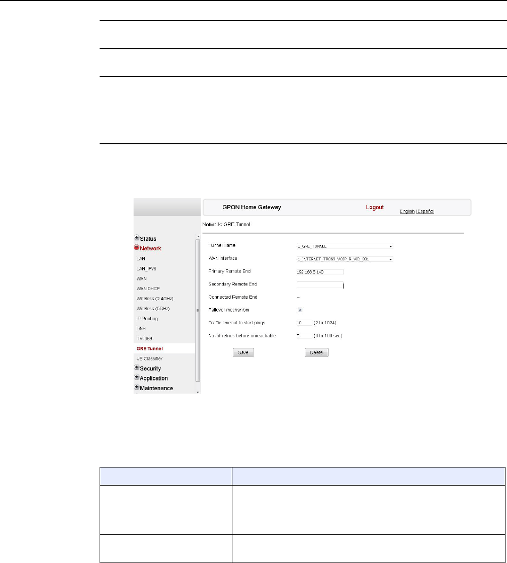
7368 ISAM ONT G-240W-F Product Guide Configure a G-240W-F indoor ONT
Issue: 01 Edition 01 107
3Click Save.
4STOP. This procedure is complete.
Procedure 22 GRE Tunnel configuration
1Select Network > GRE Tunnel from the top-level menu in the GPON Home Gateway window,
as shown in Figure 43.
Figure 43 GRE Tunnel window
Table 30 describes the fields in the GRE Tunnel window.
Table 30 GRE Tunnel parameters
Field Description
Tunnel Name Select Create new GRE Tunnel, or select an existing tunnel from the
drop-down menu.
The tunnel name is automatically assigned by the system.
Up to 3 GRE tunnels are supported.
WAN Interface Select a WAN interface from the drop-down menu.
GRE tunnels can only be created on HSI-enabled WAN interfaces.
(1 of 2)
DRAFT

Configure a G-240W-F indoor ONT
108
7368 ISAM ONT G-240W-F Product Guide
Edition 01 Issue: 01
2Configure the GRE tunnel by entering or selecting the required information.
3Click Save.
4STOP. This procedure is complete.
Procedure 23 QoS configuration
1Select Network > QoS Config from the top-level menu in the Home Gateway window.
Figure 44 shows the window for configuring QoS L2 (Layer 2 packet sizes).
Primary Remote End
Secondary Remote End (optional)
Enter an IP address or FQDN that is unique in the system.
If the primary remote endpoint is down or unreachable, the secondary
remote endpoint becomes active, if configured.
The secondary remote endpoint remains active until it becomes
unreachable, in which case the primary remote endpoint becomes active
again. Revertive mode is not supported.
If both endpoints are unreachable, the GRE tunnel is declared down.
Connected Remote End This field displays the current data traffic path for the GRE tunnel.
Failover mechanism This feature is automatically selected by the system.
Traffic timeout to start pings Enter the traffic timeout in seconds (0 to 100).
No. of retries before unreachable Enter the number of retries before the tunnel is declared down (2 to 1024).
Field Description
(2 of 2)
DRAFT
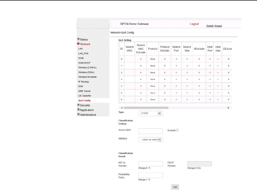
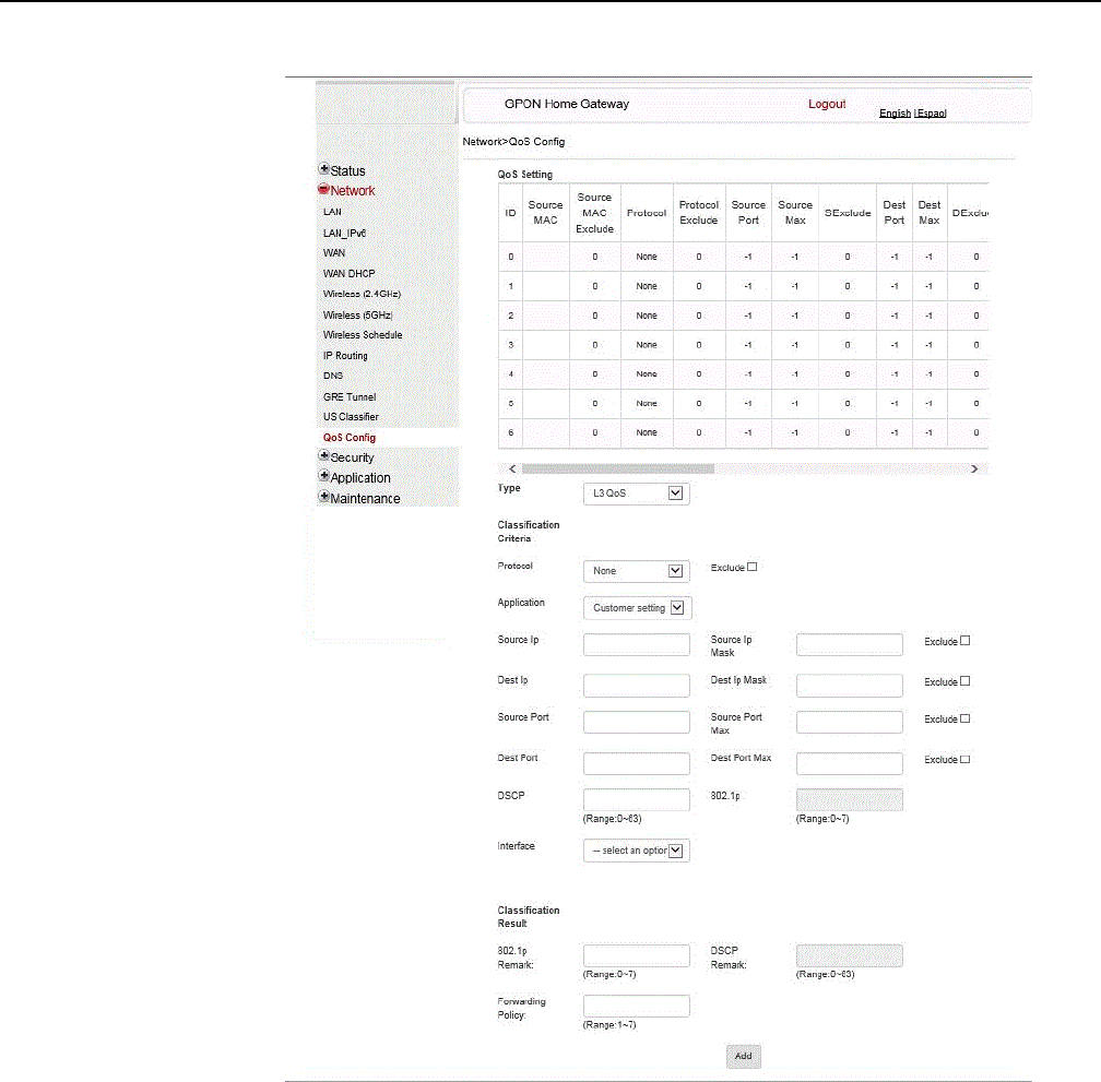

7368 ISAM ONT G-240W-F Product Guide Configure a G-240W-F indoor ONT
Issue: 01 Edition 01 111
Table 31 QoS Config parameters
2Choose a QoS type from the drop-down menu: L2 or L3.
3Configure a QoS policy.
4Click Add to add a QoS policy.
5STOP. This procedure is complete.
Procedure 24 Upstream (US) Classifier configuration
The US Classifier feature is used to create policies, classifiers, and classifier rules for upstream
traffic handling. This feature is available to admin users (super users) only.
A policy defines an action to be performed on a set of LAN or WAN packets. A policy can be
created at any time and then subsequently assigned to one or more classifiers.
A classifier is used to select key fields for which the classifier rules will be written. A classifier can
be created at any time and then subsequently assigned to one or more classifier rules.
Field Description
Type Choose a QoS service layer type from the drop-down menu L2 or L3.
Source MAC Enter the source MAC.
Select the Exclude checkbox to exclude the source MAC
Interface Choose an interface from the drop-down menu
802.1p Mark Enter the value for the 802.1p (range: 0-7)
DSCP Mark Enter the value for the DSCP mark (range: 0-63)
Forwarding Policy Enter the number for the forwarding policy (range: 1-7)
Additional fields for L3
Protocol Choose a protocol from the drop-down menu, or select the Exclude checkbox
Application Choose an application from the drop-down menu
Source IP and
Source IP Mask
Enter the values for the source IP and IP mask, or select the Exclude checkbox
Destination IP and
Destination IP Mask
Enter the values for the destination IP and IP mask, or select the Exclude checkbox
Source Port and
Source Port Max
Enter the values for the source port and port max (highest port number) or select the
Exclude checkbox
Destination Port and
Destination Port Max
Enter the values for the destination port and port max (highest port number), or select
the Exclude checkbox
DRAFT
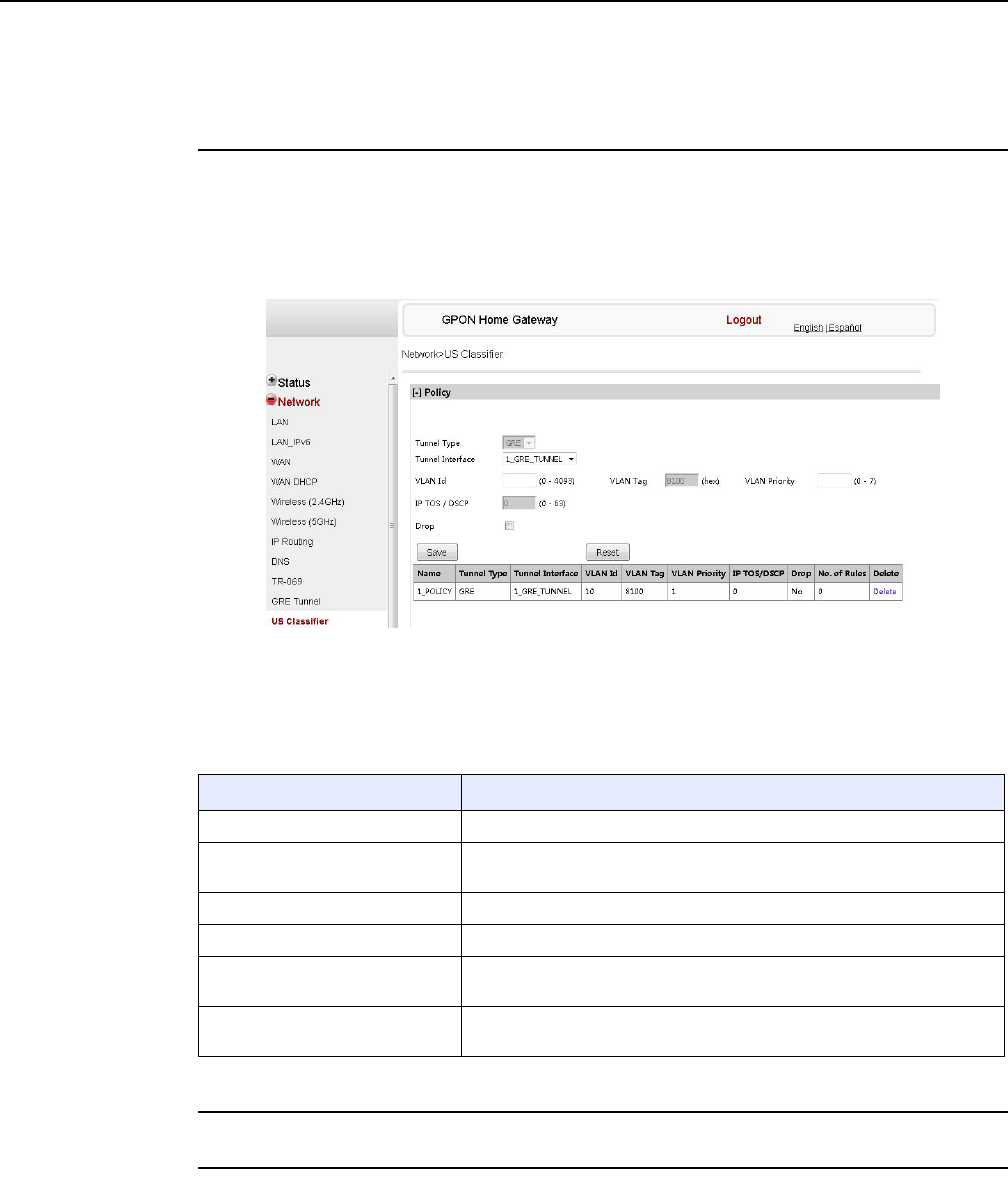
Configure a G-240W-F indoor ONT
112
7368 ISAM ONT G-240W-F Product Guide
Edition 01 Issue: 01
A classifier rule is used to assign actions to a group of packets based on a set of parameters. A
classification rule must be created against a pre-defined classifier.
Up to 16 policies can be created, with up to 8 classifiers and 32 classifier rules.
1Select Network > US Classifier from the top-level menu in the GPON Home Gateway
window, and select the Policy tab, as shown in Figure 46.
All classifier policies are displayed in the policy table in the window.
Figure 46 US Classifier Policy window
Table 32 describes the fields in the US Classifier Policy window.
Table 32 US Classifier Policy parameters
2Select a tunnel interface.
3Enter a VLAN ID and priority level.
Field Description
Tunnel Type The tunnel type is set to GRE and cannot be modified.
Tunnel Interface Select a tunnel interface from the drop-down menu: No Tunnel, GRE
Tunnel, or LAN traffic.
VLAN ID Enter a VLAN ID (0-4094).
VLAN Tag This field is not configurable. The VLAN tag is set to 8100.
VLAN Priority Enter a VLAN priority level (0 to 7). A lower number indicates a higher
priority.
IP TOS/DSCP This field is not configurable. All tunnel packets are generated with a
default DSCP value (usually 0).
DRAFT
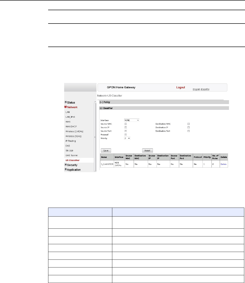
7368 ISAM ONT G-240W-F Product Guide Configure a G-240W-F indoor ONT
Issue: 01 Edition 01 113
4Click Save.
5To delete a policy, click the Delete option for the applicable policy in the policy table.
A policy can only be deleted if it is not associated with any classifier rules.
6Select Network > US Classifier from the top-level menu in the GPON Home Gateway
window, and select the Classifier tab, as shown in Figure 47.
All classifiers are displayed in the classifier table in the window.
Figure 47 US Classifier window
Table 33 describes the fields in the US Classifier window.
Table 33 US Classifier parameters
Field Description
Interface Select an interface from the drop-down menu, for example: None, LAN,
2.4G SSID, 5G SSID.
Source MAC Click to enter a source MAC.
Destination MAC Click to enter a destination MAC.
Source IP Click to enter a source IP.
Destination IP Click to enter a destination IP.
Source Port Click to enter a source port.
Destination Port Click to enter a destination port.
Protocol Click to enter a protocol.
(1 of 2)
DRAFT
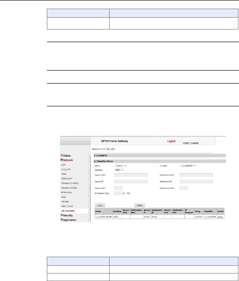
Configure a G-240W-F indoor ONT
114
7368 ISAM ONT G-240W-F Product Guide
Edition 01 Issue: 01
7Configure the US classifier.
At least one field must be selected to create a classifier. A maximum of four fields may be
selected to create a classifier; this includes the interface field.
8Click Save.
9To delete a classifier, click the Delete option for the applicable classifier in the classifier table.
A classifier can only be deleted if it is not associated with any classifier rules.
10 Select the Classifier Rules tab, as shown in Figure 48.
All classifier rules are displayed in the classifier rules table in the window.
Figure 48 US Classifier Rules window
Table 34 describes the fields in the US Classifier Rules window.
Table 34 US Classifier Rules parameters
Priority Select a priority level from 1 to 8. The lower the number, the higher the
priority. No more than 1 classifier can be created with the same priority.
Field Description
Policy Select a policy from the drop-down menu.
Classifier Select a classifier from the drop-down menu.
(1 of 2)
Field Description
(2 of 2)
DRAFT

7368 ISAM ONT G-240W-F Product Guide Configure a G-240W-F indoor ONT
Issue: 01 Edition 01 115
11 Configure the classifier rule.
12 Click Save.
13 To delete a classifier rule, click the Delete option for the applicable classifier rule in the
classifier rules table.
14 STOP. This procedure is complete.
8.2.4 Security configuration
G-240W-F ONT also supports security configuration, including:
•firewall
•MAC filter
•IP filter
•URL filter
•parental control
•DMZ and ALG
•access control
Interface Select an interface from the drop-down menu, for example: None, LAN,
2.4G SSID, 5G SSID.
Source MAC Enter a source MAC.
Destination MAC Enter a destination MAC.
Source IP Enter a source IP.
Destination IP Enter a destination IP.
Source Port Enter a source port.
Destination Port Enter a destination port.
IP Protocol type Enter a value between 0 and 254.
Field Description
(2 of 2)
DRAFT
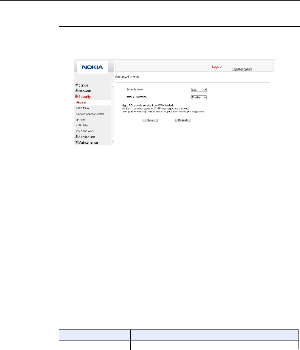
Configure a G-240W-F indoor ONT
116
7368 ISAM ONT G-240W-F Product Guide
Edition 01 Issue: 01
Procedure 25 Firewall configuration
1Select Security > Firewall from the top-level menu in the GPON Home Gateway window, as
shown in Figure 49.
Figure 49 Firewall window
Firewall security applies only to services provided by the ONT. Internet access from the LAN
side is not affected by this firewall.
Three security levels are available: Low, Medium, and High.
At the Low level, pre-routing is supported: port forwarding, DMZ, host application, and host
drop. Also supported are application services: DDNS, DHCP, DNS, H248, IGMP, NTP client,
SSH, Telnet, TFTP, TR-069, and VoIP.
At the Medium level, pre-routing is supported: port forwarding, DMZ, host application, and
host drop. Also supported are application services: DDNS, DHCP, DNS, H248, IGMP, NTP
client, TFTP, TR-069, and VoIP. The following types of ICMP messages are permitted: echo
request and reply, destination unreachable, and TTL exceeded. Other types of ICMP
messages are blocked. DNS proxy is supported from LAN to WAN but not from WAN to LAN.
At the High level, pre-routing and application services are not supported. UDP Port 8000 can
be used to access the services, for example FTP can use 8021 and Telnet can use 8023.
Regular UDP cannot be used. RG access is permitted via the LAN side but not via the WAN
side.
Table 35 describes the fields in the firewall window.
Table 35 Firewall parameters
Field Description
Security level Choose the security level from the drop-down menu: low, medium, or high
(1 of 2)
DRAFT
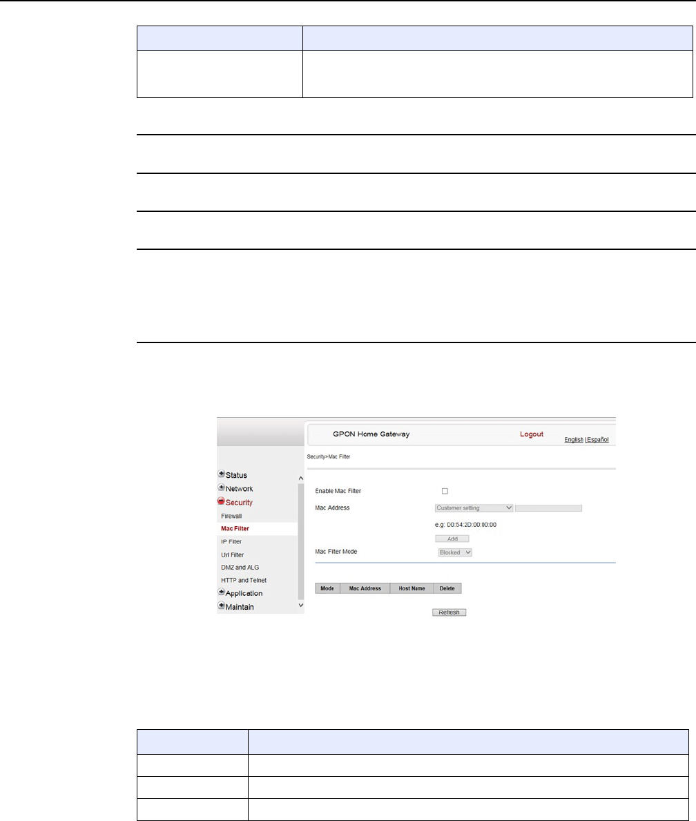
7368 ISAM ONT G-240W-F Product Guide Configure a G-240W-F indoor ONT
Issue: 01 Edition 01 117
2Configure the firewall.
3Click Save.
4STOP. This procedure is complete.
Procedure 26 MAC filter configuration
1Select Security > Mac Filter from the top-level menu in the GPON Home Gateway window,
as shown in Figure 50.
Figure 50 MAC filter window
Table 36 describes the fields in the MAC filter window.
Table 36 MAC filter parameters
Attack Protect
(Protection against DoS or
DDoS attacks)
Choose enable or disable attack protect from the drop-down menu
The default is disable
Field Description
(2 of 2)
Field Description
Enable MAC filter Select this checkbox to enable the MAC filter
Mac Address Select a MAC address from the drop-down menu or enter the address in the text field
Mac Filter Mode Choose the MAC filter mode from this drop-down menu: Blocked or Allowed
DRAFT
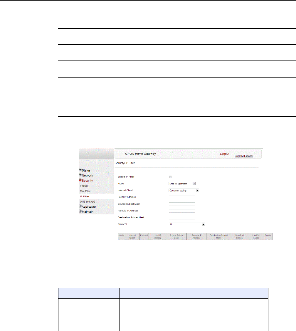
Configure a G-240W-F indoor ONT
118
7368 ISAM ONT G-240W-F Product Guide
Edition 01 Issue: 01
2Click Refresh to update the information.
3Configure a MAC filter.
4Click Add.
5STOP. This procedure is complete.
Procedure 27 IP filter configuration
1Select Security > IP filter from the top-level menu in the GPON Home Gateway window, as
shown in Figure 51.
Figure 51 IP filter window
Table 37 describes the fields in the IP filter window.
Table 37 IP filter parameters
Field Description
Enable IP Filter Select this checkbox to enable an IP filter
Mode Choose an IP filter mode from the drop-down menu:
•Drop for upstream
•Drop for downstream
(1 of 2)
DRAFT
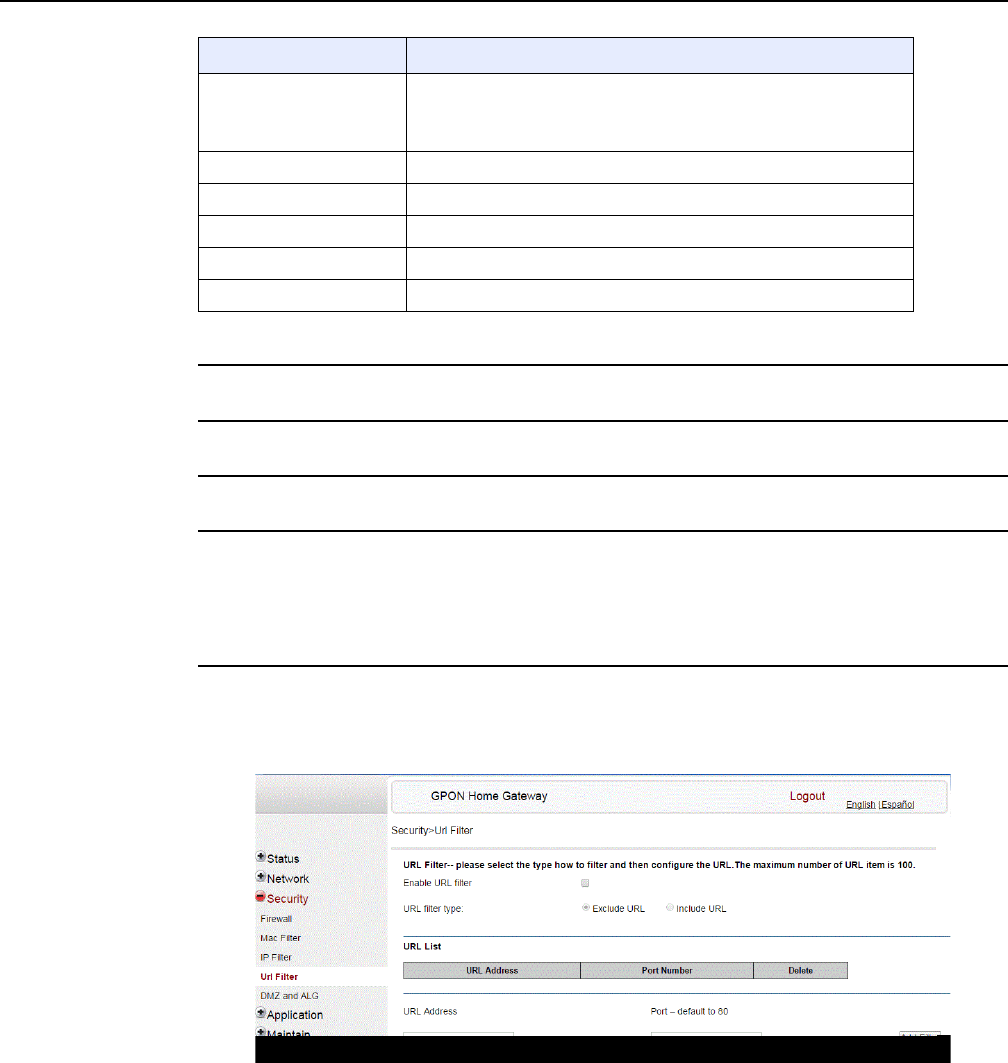
7368 ISAM ONT G-240W-F Product Guide Configure a G-240W-F indoor ONT
Issue: 01 Edition 01 119
2Configure the IP filter.
3Click Add.
4STOP. This procedure is complete.
Procedure 28 URL filter configuration
1Select Security > URL Filter from the top-level menu in the GPON Home Gateway window,
as shown in Figure 52.
Figure 52 URL Filter window
Table 38 describes the fields in the URL Filter window.
Internal Client Choose an internal client from the drop-down menu:
•Customer setting - uses the IP address input below
•IP - uses the connecting devices' IP to the ONT
Local IP Address Local IP address
Source Subnet Mask Source subnet mask
Remote IP Address Remote IP address
Destination Subnet Mask Destination subnet mask
Protocol Choose an application protocol or all from the drop-down menu
Field Description
(2 of 2)
DRAFT
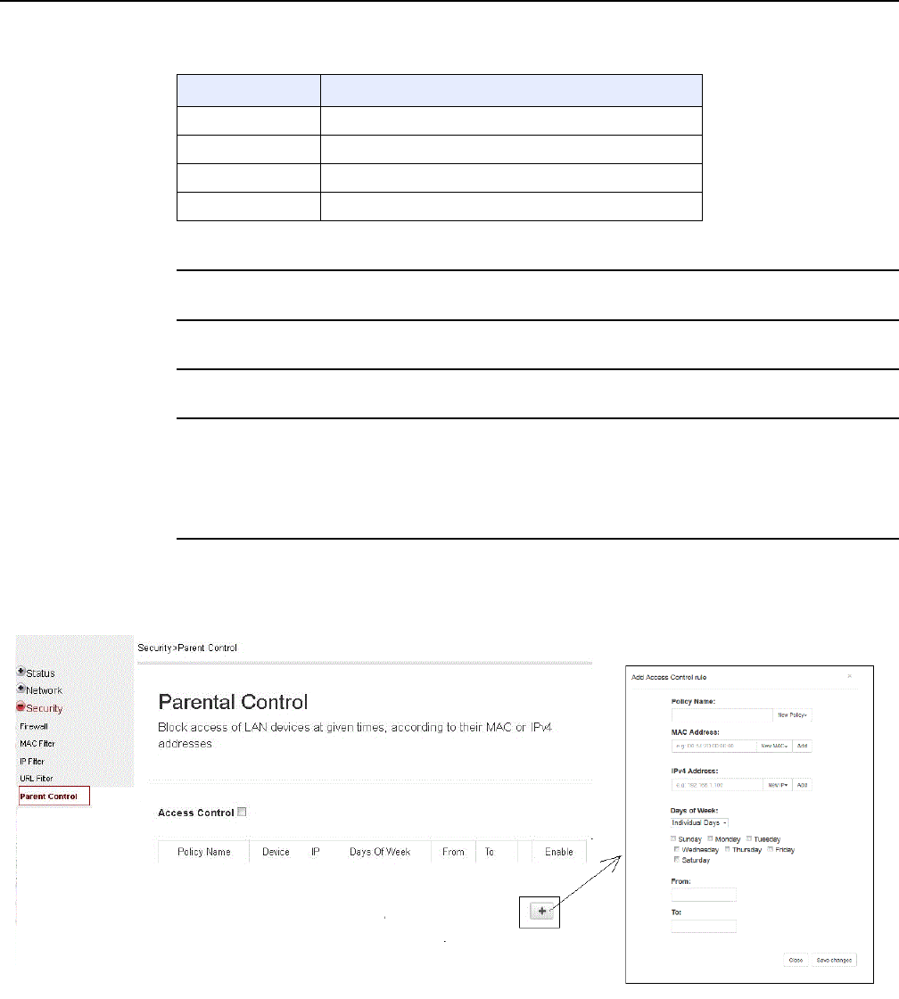
Configure a G-240W-F indoor ONT
120
7368 ISAM ONT G-240W-F Product Guide
Edition 01 Issue: 01
Table 38 URL Filter parameters
2Configure the URL Filter.
3Click Add Filter.
4STOP. This procedure is complete.
Procedure 29 Parental control
1Select Security > Parent Control from the top-level menu in the GPON Gateway window, as
shown in Figure 53.
Figure 53 Parental Control window
Table 39 describes the fields in the Parental Control window.
Field Description
Enable URL filter Select the checkbox to enable the URL filter
URL filter type Select the checkbox for Exclude URL or Include URL
URL Address Type the URL address
Port Number Type the port number; the default is 80
DRAFT

7368 ISAM ONT G-240W-F Product Guide Configure a G-240W-F indoor ONT
Issue: 01 Edition 01 121
Table 39 Parental control parameters
2Select the Access Control checkbox.
3Click the plus sign (+) to add a policy.
A separate panel displays for configuring the policy name, IP address of the device, and
dates and times for the policy.
4Configure the parental control policy.
5Click Enable to activate the policy.
6STOP. This procedure is complete.
Field Description
Policy Name Enter a name for the parental control policy or choose a policy from the list
MAC Address Enter the MAC address or choose a MAC address from the list
IPv4 Address Enter the IPv4 address for the device or choose an IPv4 address from the list
Days of the week Choose Every Day, or Individual Days and select the checkboxes for the days of the week
for which the policy applies
From/To Enter the times for the policy to be in effect
DRAFT
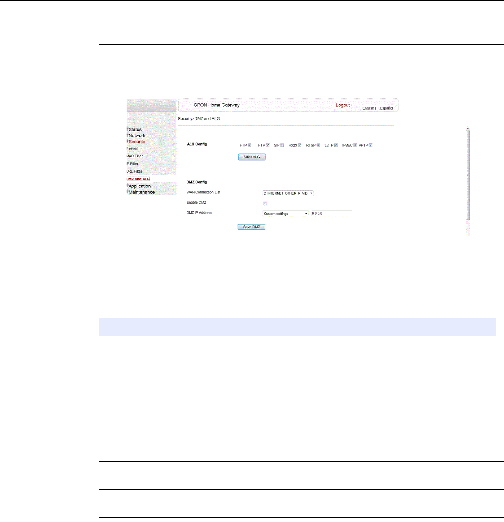
Configure a G-240W-F indoor ONT
122
7368 ISAM ONT G-240W-F Product Guide
Edition 01 Issue: 01
Procedure 30 DMZ and ALG configuration
1Select Security > DMZ and ALG from the top-level menu in the GPON Home Gateway
window, as shown in Figure 54.
Figure 54 DMZ and ALG window
Table 40 describes the fields in the DMZ and ALG window.
Table 40 DMZ and ALG parameters
2Configure ALG.
3Click Save ALG.
4Configure DMZ.
Field Description
ALG Config Select the checkboxes to enable the protocols to be supported by the ALG: FTP,
TFTP, SIP, H323, RTSP, L2TP, IPSEC, PPTP
DMZ Config
WAN Connection List Choose a WAN connection from the drop-down menu
Enable DMZ Select this checkbox to enable DMZ on the chosen WAN connection
DMZ IP Address Choose Customer Setting and enter the DMZ IP address or choose the IP address
of a connected device from the drop-down menu
DRAFT
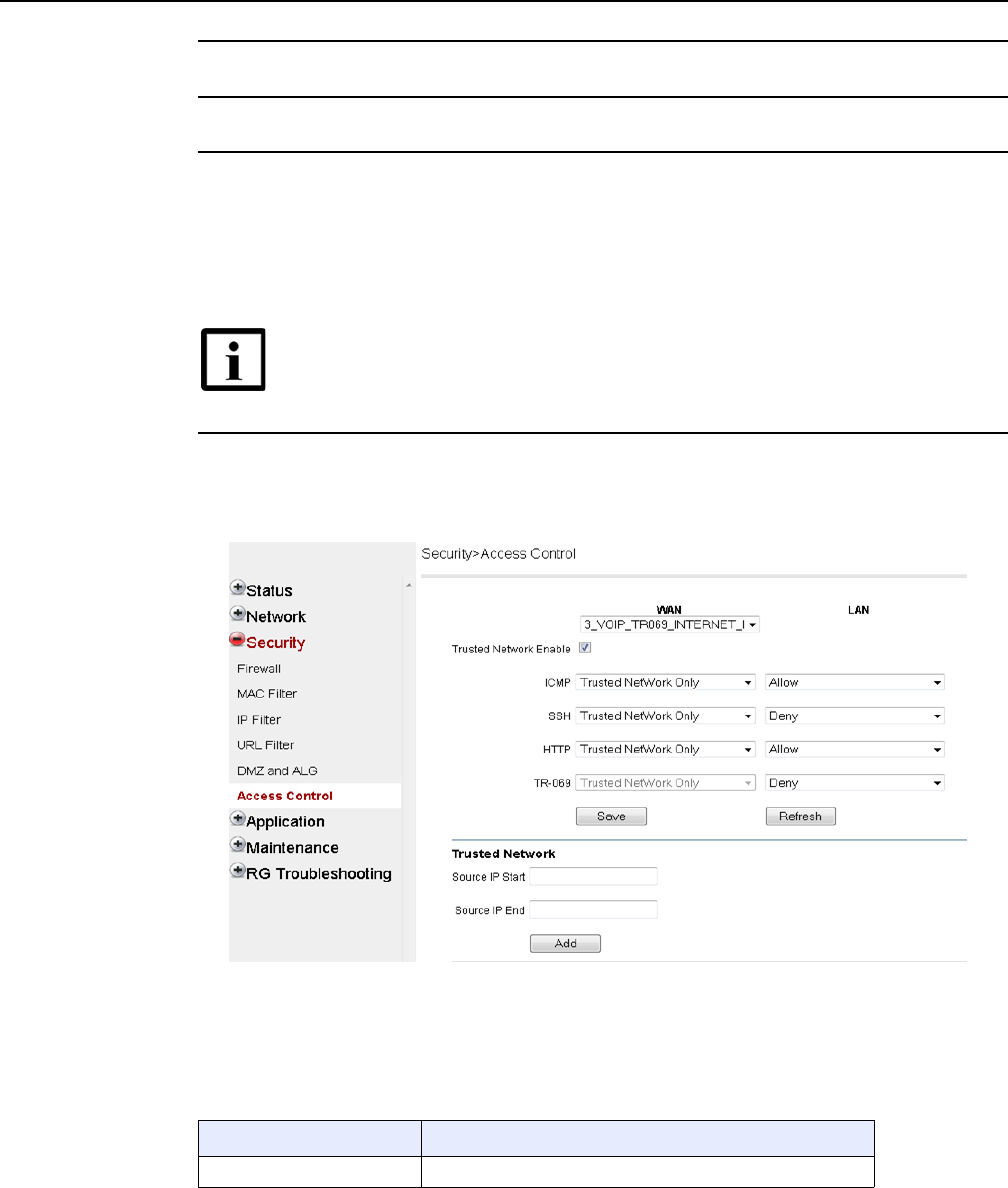
7368 ISAM ONT G-240W-F Product Guide Configure a G-240W-F indoor ONT
Issue: 01 Edition 01 123
5Click Save DMZ.
6STOP. This procedure is complete.
Procedure 31 Access control configuration
This procedure describes how to configure the access control level (ACL).
1Select Security > Access Control from the top-level menu in the GPON Home Gateway
window, as shown in Figure 55.
Figure 55 Access Control window
Table 41 describes the fields in the Access Control window.
Table 41 Access control parameters
Note 1 — ACL takes precedence over the firewall policy.
Note 2 — The trusted network object will be shared for all WAN
connections; it is not applied individually to a WAN connection.
Field Description
WAN Choose a connection from the drop-down menu
(1 of 2)
DRAFT

Configure a G-240W-F indoor ONT
124
7368 ISAM ONT G-240W-F Product Guide
Edition 01 Issue: 01
2Select a WAN connection from the drop-down menu.
3Click to enable or disable Trusted Network.
4Select an access control level for each of the four protocols: ICMP, SSH, HTTP, and TR-069
for both the WAN and the LAN side.
5Click Save.
6Optionally, add one or more subnet trusted networks.
The maximum number of entries is 32.
You can also use the Source IP fields to delete a previously created entry for a subnet trusted
network.
7STOP. This procedure is complete.
8.2.5 Application configuration
G-240W-F ONT also supports application configuration, including:
•port forwarding
•port triggering
•DDNS
•NTP
•USB storage
•UPnP and DLNA
Trusted Network Enable Click to enable or disable
ICMP, SSH, HTTP, TR-069 Select an access control level for each protocol:
WAN side: Allow, Deny, or Trusted Network Only
LAN side: Allow or Deny
Source IP Start Enter a start IP address for the new subnet trusted network
Source IP End Enter an end IP address for the new subnet trusted network
Field Description
(2 of 2)
DRAFT
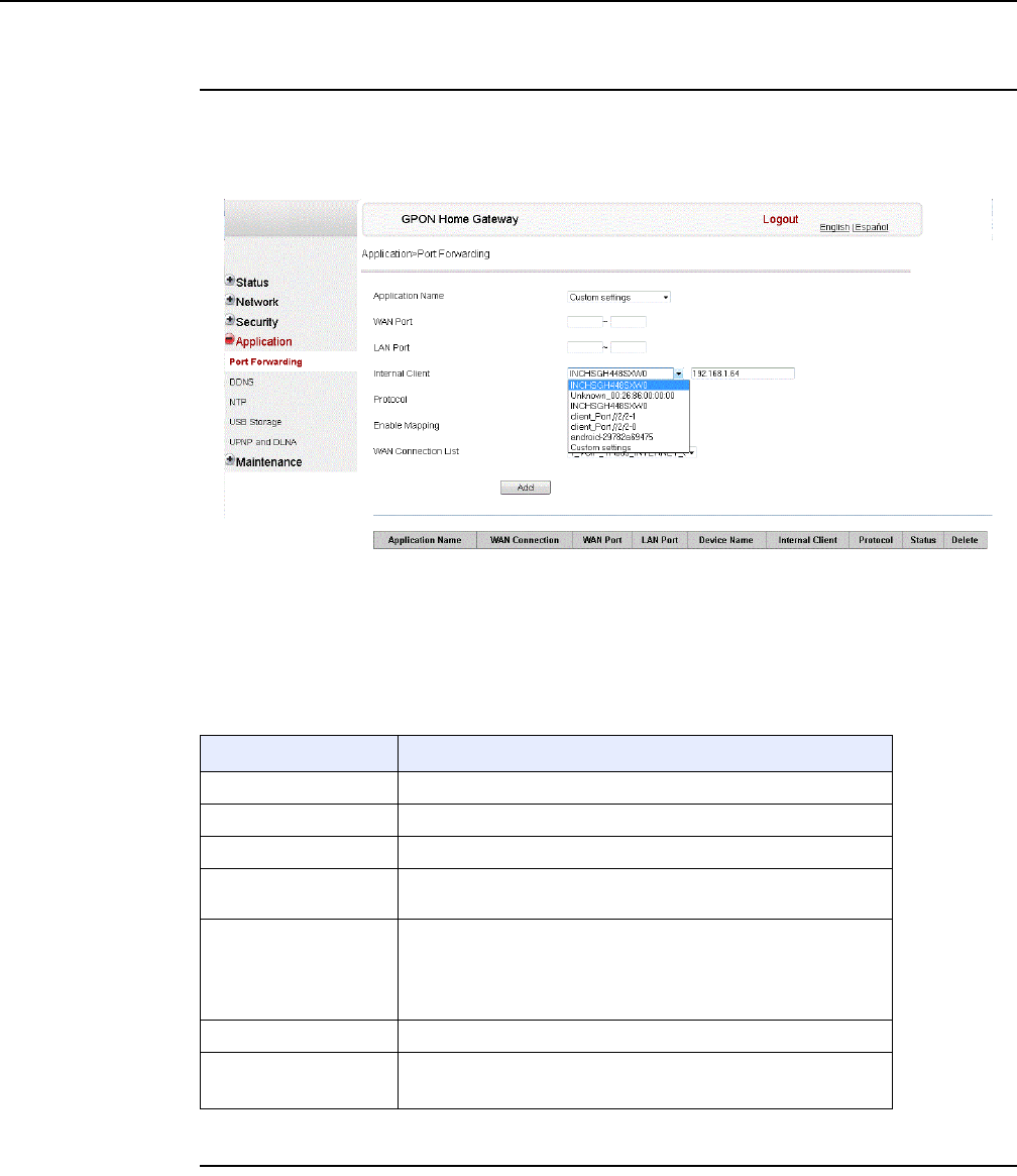
7368 ISAM ONT G-240W-F Product Guide Configure a G-240W-F indoor ONT
Issue: 01 Edition 01 125
Procedure 32 Port forwarding configuration
1Select Application > Port forwarding from the top-level menu in the GPON Home Gateway
window, as shown in Figure 56.
Figure 56 Port forwarding window
Table 42 describes the fields in the port forwarding window.
Table 42 Port forwarding parameters
2Configure port forwarding.
Field Description
APPName Choose an application name from the drop-down menu
WAN Port WAN port range
LAN Port LAN port range
Internal Client Choose a connected device from the drop-down menu and enter
the associated IP address
Protocol Choose the port forwarding protocol from the drop-down menu:
•TCP
•UDP
•TCP/UDP
Enable Mapping Select this checkbox to enable mapping
WAN Connection List Choose a WAN connection from the drop-down menu
Note: only active devices are shown on this menu
DRAFT
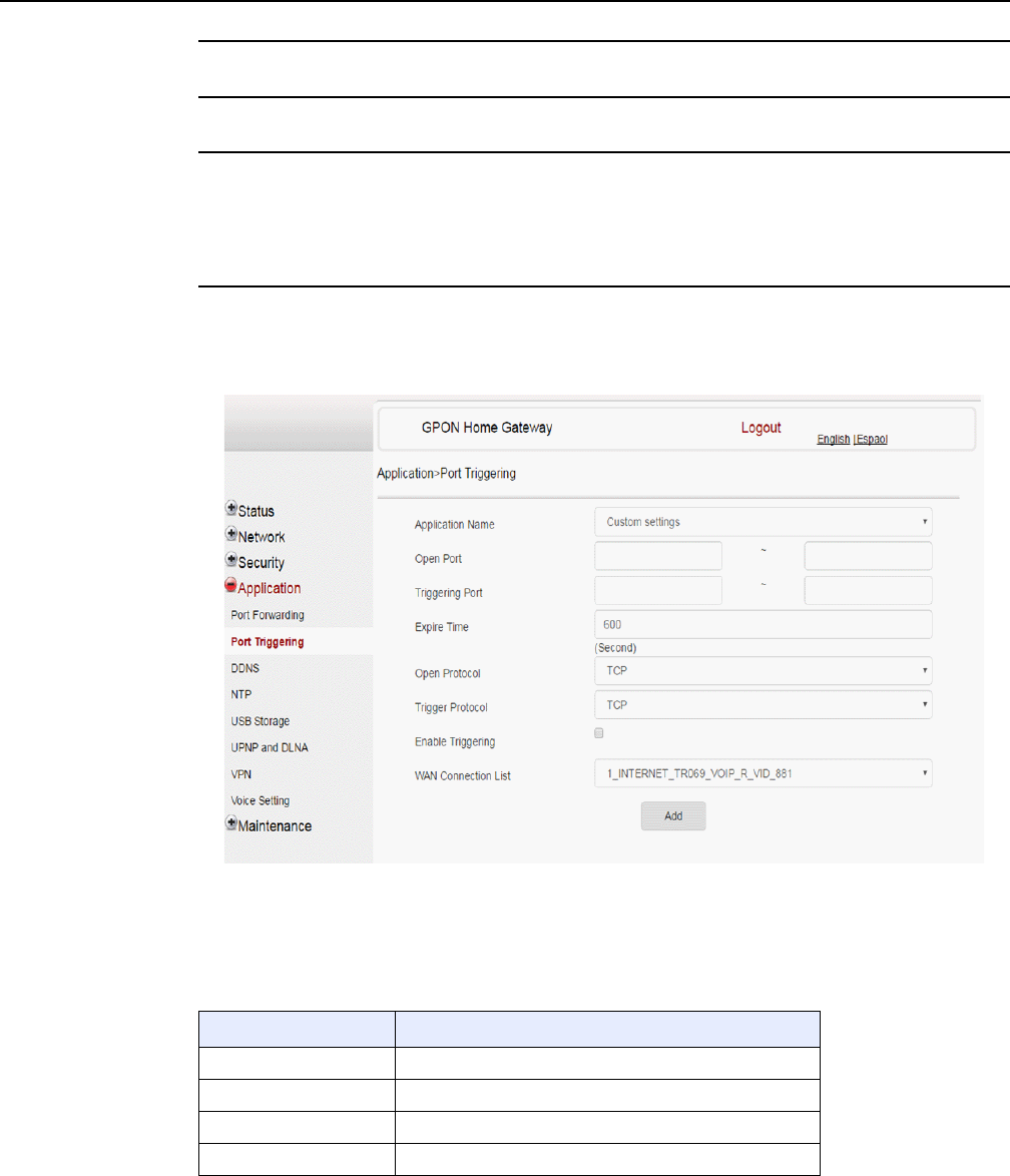
Configure a G-240W-F indoor ONT
126
7368 ISAM ONT G-240W-F Product Guide
Edition 01 Issue: 01
3Click Add.
4STOP. This procedure is complete.
Procedure 33 Port triggering
1Select Application > Port Triggering from the top-level menu in the GPON Gateway window,
as shown in Figure 57.
Figure 57 Port Triggering window
Table 43 describes the fields in the Port Triggering window.
Table 43 Port triggering parameters
Field Description
Application Name Choose an application name from the drop-down menu
Open Port Enter the open port range
Triggering Port Enter the triggering port range
Expire Time Enter the expiration time in seconds
(1 of 2)
DRAFT
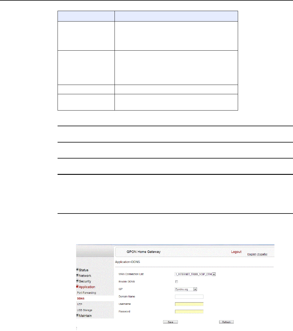
7368 ISAM ONT G-240W-F Product Guide Configure a G-240W-F indoor ONT
Issue: 01 Edition 01 127
2Configure port triggering.
3Click Add.
4STOP. This procedure is complete.
Procedure 34 DDNS configuration
1Select Application > DDNS from the top-level menu in the GPON Home Gateway window, as
shown in Figure 58.
Figure 58 DDNS window
Table 44 describes the fields in the DDNS window.
Open Protocol Choose the open port protocol from the drop-down menu:
•TCP
•UDP
•TCP/UDP
Trigger Protocol Choose the triggering port protocol from the drop-down
menu:
•TCP
•UDP
•TCP/UDP
Enable Triggering Select this checkbox to enable port triggering
WAN Connection List Choose a WAN connection from the drop-down menu
Note: only active devices are shown on this menu
Field Description
(2 of 2)
DRAFT
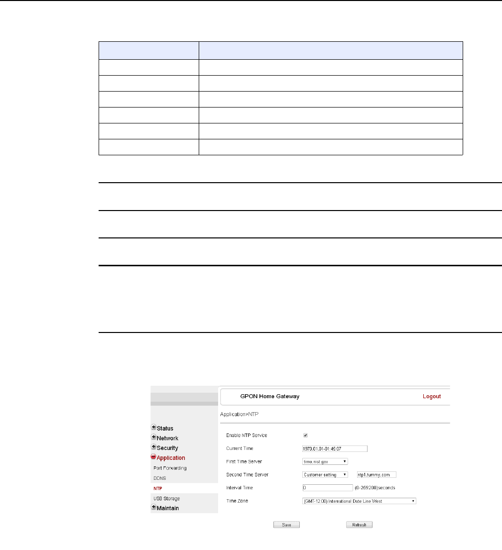
Configure a G-240W-F indoor ONT
128
7368 ISAM ONT G-240W-F Product Guide
Edition 01 Issue: 01
Table 44 DDNS parameters
2Configure DDNS.
3Click Save.
4STOP. This procedure is complete.
Procedure 35 NTP configuration
1Select Application > NTP from the top-level menu in the GPON Home Gateway window, as
shown in Figure 59.
Figure 59 NTP window
Table 45 describes the fields in the NTP window.
Field Description
WAN Connection List Choose a WAN connection from the drop-down menu
Enable DDNS Select this checkbox to enable DDNS on the chosen WAN connection
ISP Choose an ISP from the drop-down menu.
Domain Name Domain name
Username Username
Password Password
DRAFT
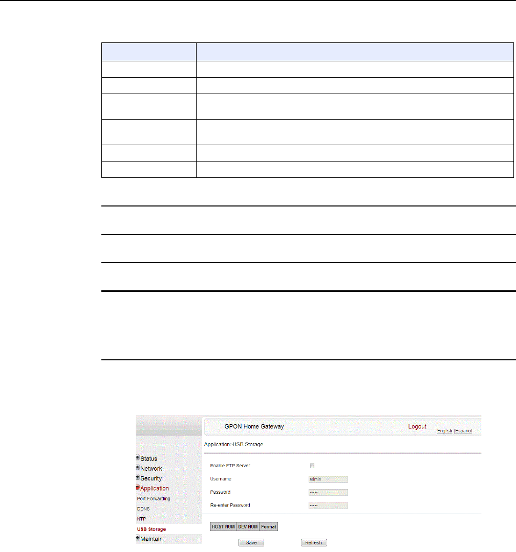
7368 ISAM ONT G-240W-F Product Guide Configure a G-240W-F indoor ONT
Issue: 01 Edition 01 129
Table 45 NTP parameters
2Configure NTP.
3Click Save.
4STOP. This procedure is complete.
Procedure 36 USB storage configuration
1Select Application > USB storage from the top-level menu in the GPON Home Gateway
window, as shown in Figure 60.
Figure 60 USB storage window
Table 46 describes the fields in the USB storage window.
Field Description
Enable NTP Service Select this checkbox to enable NTP service
Current Time Enter the current local date and time
First Time Server Choose a time server from the drop-down menu or choose Customer setting and
enter the address of the time server.
Second Time Server Choose a time server from the drop-down menu or choose Customer setting and
enter the address of the time server.
Interval Time Interval at which to get the time from the time server, in seconds
Time Zone Choose the local time zone from the drop-down menu
DRAFT
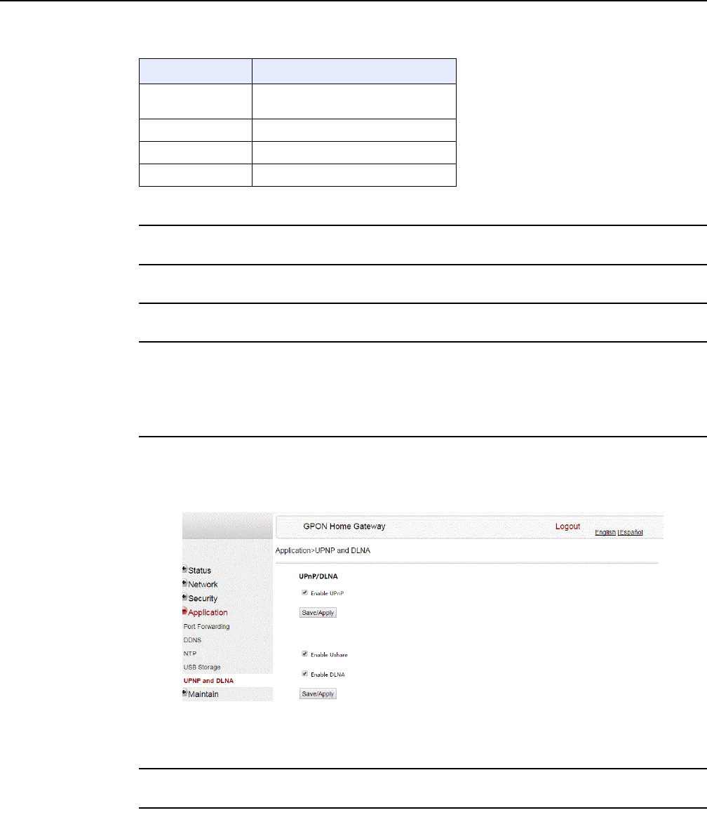
Configure a G-240W-F indoor ONT
130
7368 ISAM ONT G-240W-F Product Guide
Edition 01 Issue: 01
Table 46 USB storage parameters
2Configure USB storage.
3Click Save.
4STOP. This procedure is complete.
Procedure 37 UPnP and DLNA configuration
1Select Application > UPnP and DLNA from the top-level menu in the GPON Home Gateway
window, as shown in Figure 61.
Figure 61 UPnP and DLNA window
2Select the Enable UPnP checkbox to enable UPnP.
3Click Save/Apply.
Field Description
Enable FTP server Select this checkbox to enable using
an FTP server for data storage
Username Username for FTP server
Password Password for FTP server
Re-enter Password Password for FTP server
DRAFT

7368 ISAM ONT G-240W-F Product Guide Configure a G-240W-F indoor ONT
Issue: 01 Edition 01 131
4Select the Enable Ushare checkbox to enable Ushare (the UPnP/DLNA media server).
5Select the Enable DLNA checkbox to enable DLNA.
6Click Save/Apply.
7STOP. This procedure is complete.
8.2.6 Maintenance
G-240W-F ONT also supports maintenance tasks, including:
•change password
•configure LOID
•configure SLID
•manage device
•backup and restore
•upgrade firmware
•reboot device
•restore factory defaults
•diagnose WAN connections
•log
•diagnose PPPoE connectivity
DRAFT
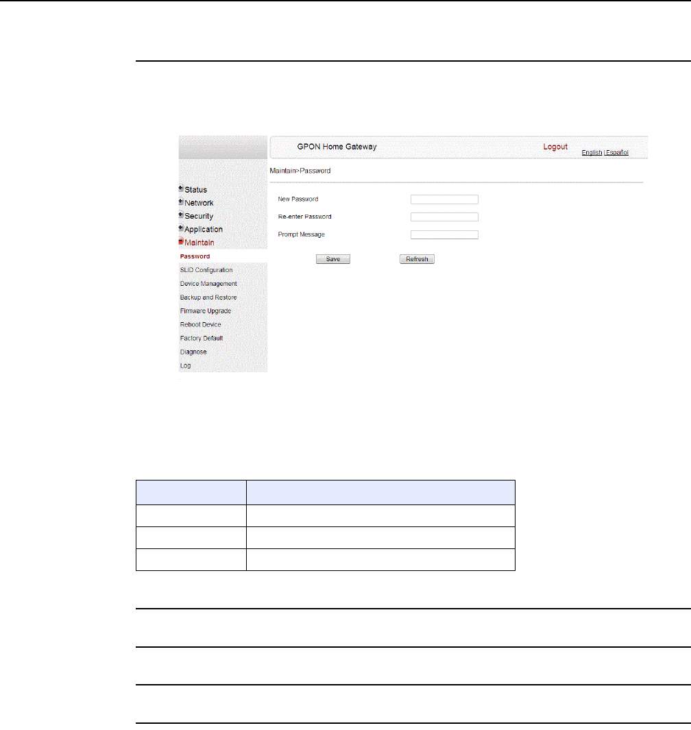
Configure a G-240W-F indoor ONT
132
7368 ISAM ONT G-240W-F Product Guide
Edition 01 Issue: 01
Procedure 38 Password configuration
1Select Maintain > Password from the top-level menu in the GPON Home Gateway window,
as shown in Figure 62.
Figure 62 Password window
Table 47 describes the fields in the password window.
Table 47 Password parameters
2Configure the new password.
3Click Save.
4STOP. This procedure is complete.
Field Description
New Password New password
Re-enter password Password must match password entered above
Prompt message Password prompt message
DRAFT
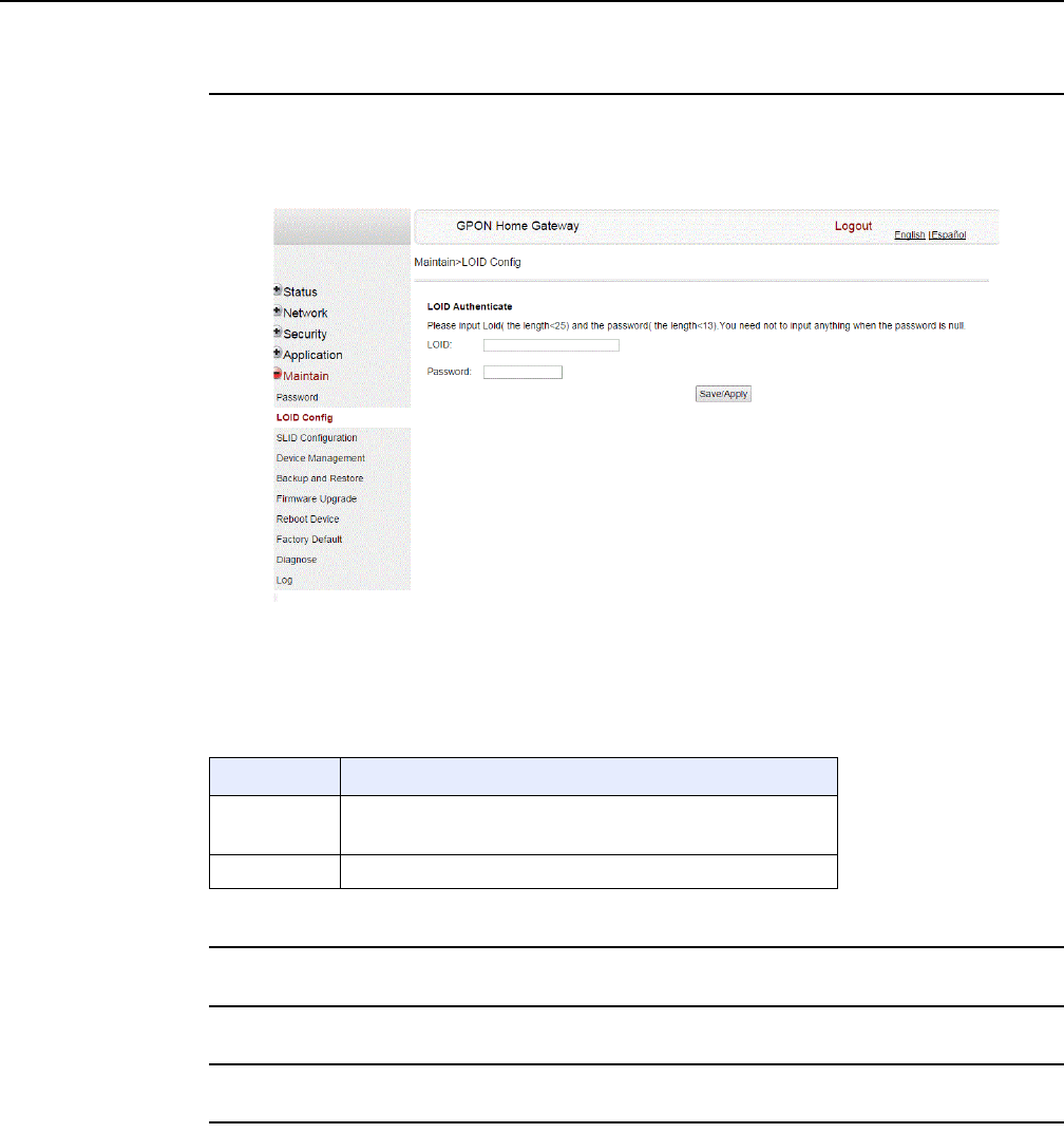
7368 ISAM ONT G-240W-F Product Guide Configure a G-240W-F indoor ONT
Issue: 01 Edition 01 133
Procedure 39 LOID configuration
1Select Maintain > LOID Config from the top-level menu in the GPON Home Gateway window,
as shown in Figure 63.
Figure 63 LOID Config window
Table 48 describes the fields in the LOID configuration window.
Table 48 LOID configuration parameters
2Configure the LOID.
3Click Save/Apply.
4STOP. This procedure is complete.
Field Description
LOID Type the LOID; the maximum number of characters is 24
If the password is null, this field may be left blank
Password Type the password; the maximum number of characters is 12
DRAFT
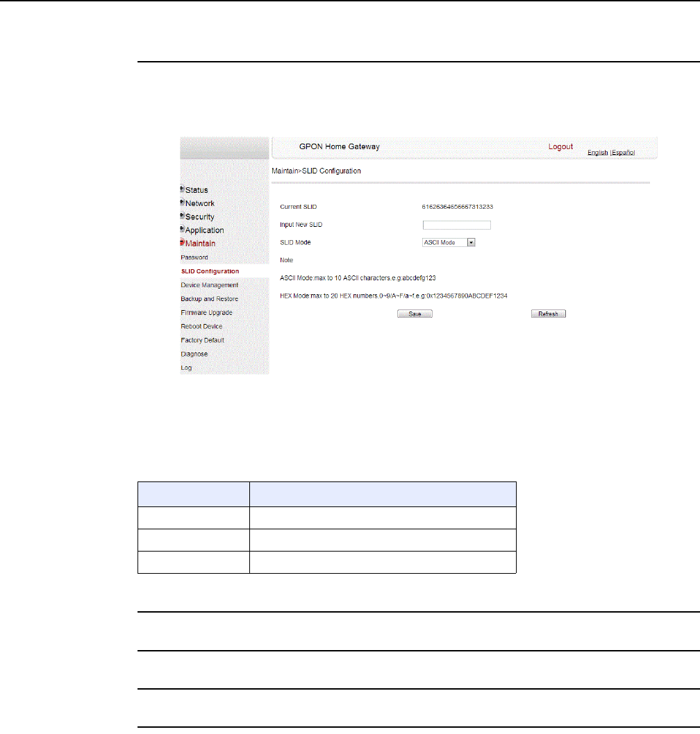
Configure a G-240W-F indoor ONT
134
7368 ISAM ONT G-240W-F Product Guide
Edition 01 Issue: 01
Procedure 40 SLID configuration
1Select Maintain > SLID Configuration from the top-level menu in the GPON Home Gateway
window, as shown in Figure 64.
Figure 64 SLID configuration window
Table 49 describes the fields in the SLID configuration window.
Table 49 SLID configuration parameters
2Configure the new SLID.
3Click Save.
4STOP. This procedure is complete.
Field Description
Current SLID Displays current SLID
Input new SLID Enter new SLID
SLID Mode Choose a SLID mode from the drop-down menu.
DRAFT
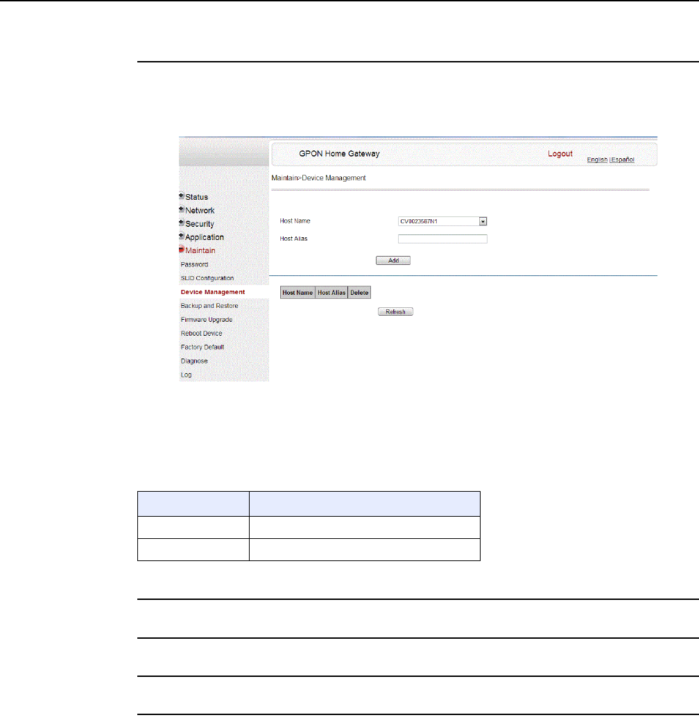
7368 ISAM ONT G-240W-F Product Guide Configure a G-240W-F indoor ONT
Issue: 01 Edition 01 135
Procedure 41 Device management
1Select Maintain > Device Management from the top-level menu in the GPON Home Gateway
window, as shown in Figure 65.
Figure 65 Device management window
Table 50 describes the fields in the Device management window.
Table 50 Device management parameters
2Configure an alias for a specific host.
3Click Add.
4STOP. This procedure is complete.
Field Description
Host name Choose a host from the drop-down menu
Alias Enter an alias for the chosen host
DRAFT
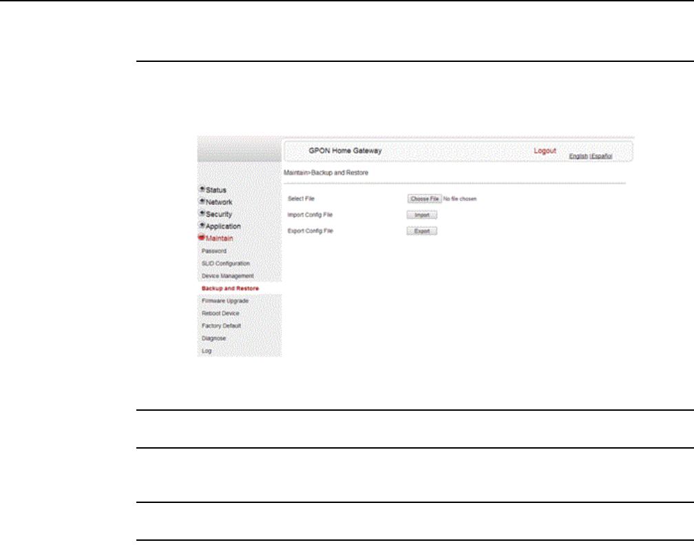
Configure a G-240W-F indoor ONT
136
7368 ISAM ONT G-240W-F Product Guide
Edition 01 Issue: 01
Procedure 42 Backup and restore
1Select Maintain > Backup and Restore from the top-level menu in the GPON Home Gateway
window, as shown in Figure 66.
Figure 66 Backup and Restore window
2Click Select File and choose the backup file.
3Click Import Config File to restore the ONT to the saved backup or click Export Config File to
export the current ONT configuration to the backup file.
4STOP. This procedure is complete.
DRAFT
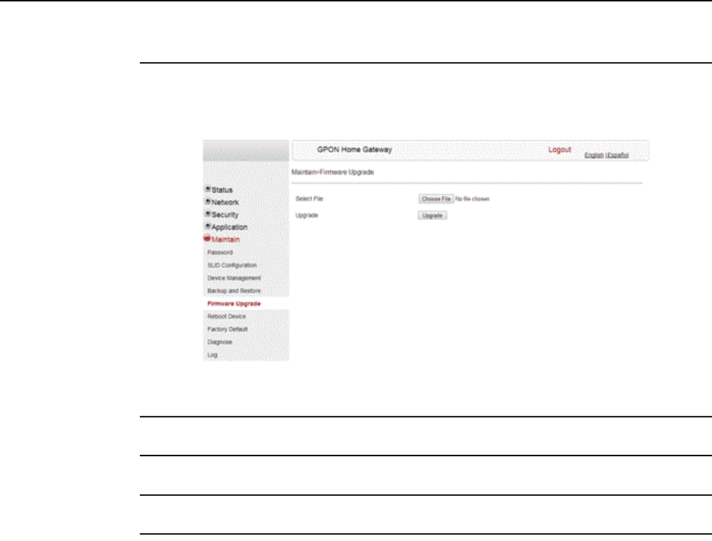
7368 ISAM ONT G-240W-F Product Guide Configure a G-240W-F indoor ONT
Issue: 01 Edition 01 137
Procedure 43 Upgrade firmware
1Select Maintain > Firmware Upgrade from the top-level menu in the GPON Home Gateway
window, as shown in Figure 67.
Figure 67 Firmware upgrade window
2Click Select File and choose the firmware file.
3Click Upgrade to upgrade the firmware.
4STOP. This procedure is complete.
DRAFT
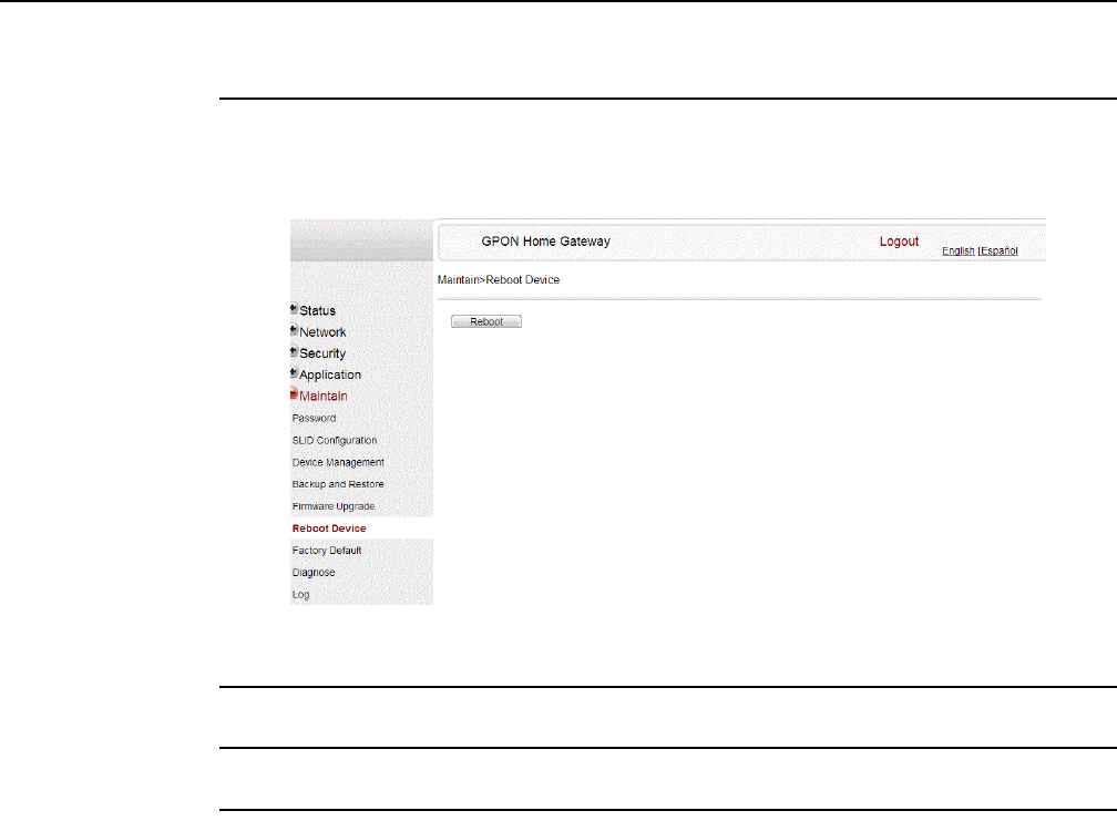
Configure a G-240W-F indoor ONT
138
7368 ISAM ONT G-240W-F Product Guide
Edition 01 Issue: 01
Procedure 44 Reboot ONT
1Select Maintain > Reboot Device from the top-level menu in the GPON Home Gateway
window, as shown in Figure 68.
Figure 68 Reboot window
2Click Reboot to reboot the ONT.
3STOP. This procedure is complete.
DRAFT
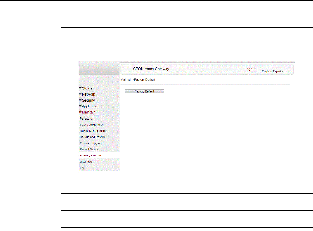
7368 ISAM ONT G-240W-F Product Guide Configure a G-240W-F indoor ONT
Issue: 01 Edition 01 139
Procedure 45 Restore factory defaults
1Select Maintain > Factory Default from the top-level menu in the GPON Home Gateway
window, as shown in Figure 69.
Figure 69 Factory default window
2Click Factory Default to reset the ONT to its factory default settings.
3STOP. This procedure is complete.
DRAFT
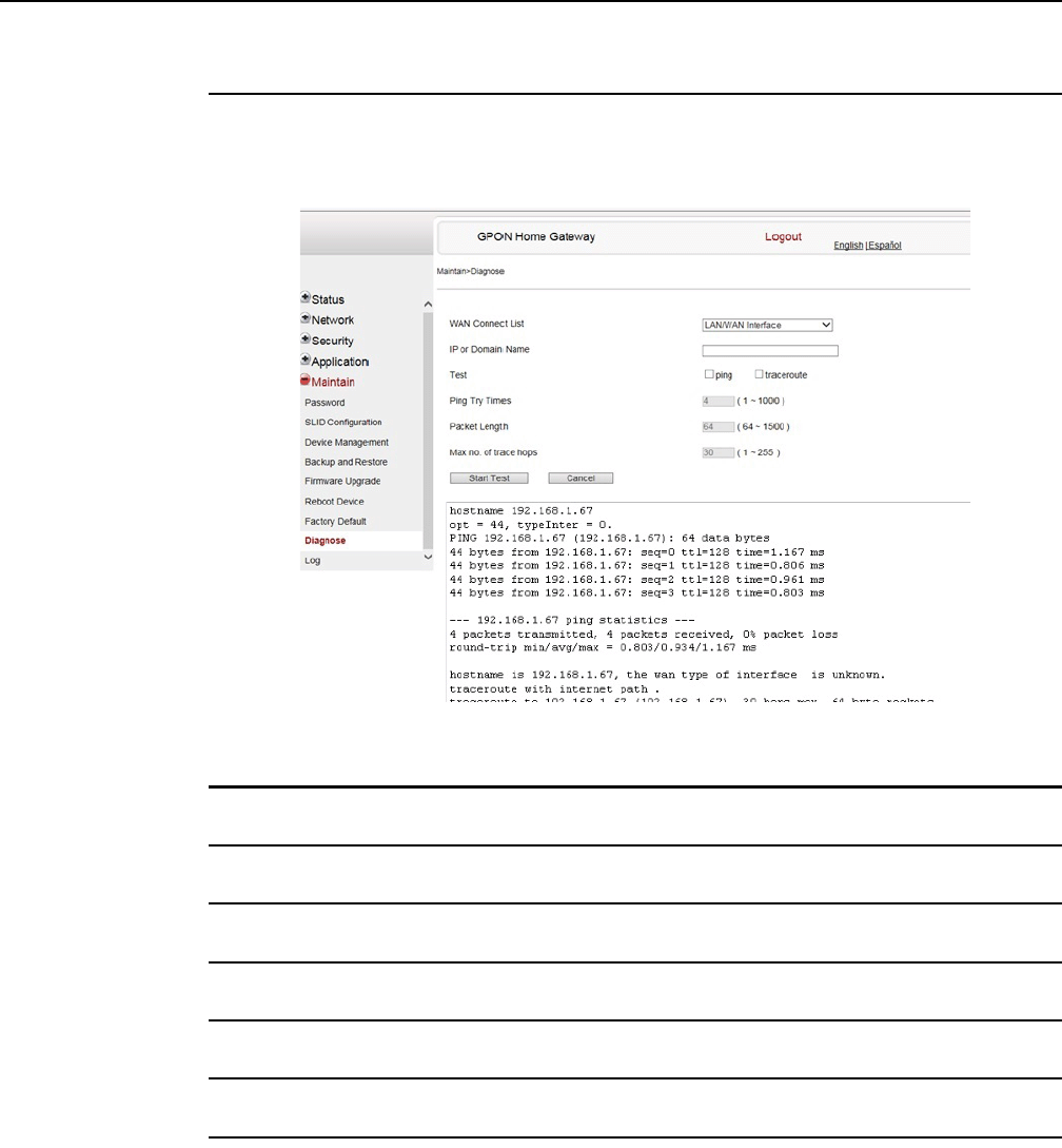
Configure a G-240W-F indoor ONT
140
7368 ISAM ONT G-240W-F Product Guide
Edition 01 Issue: 01
Procedure 46 Diagnose WAN connections
1Select Maintain > Diagnose from the top-level menu in the GPON Home Gateway window,
as shown in Figure 70.
Figure 70 Diagnose window
2Choose a WAN connection to diagnose from the drop-down menu.
3Enter the IP address or domain name.
4Select the test type: ping, traceroute, or both.
5Enter the number of ping attempts to perform (1 - 1000); the default is 4.
6Enter a ping packet length (64-1024); the default is 64.
7Enter the maximum number of trace hops (1-255); the default is 30.
8Click Start Test. Results will be displayed at the bottom of the window.
DRAFT
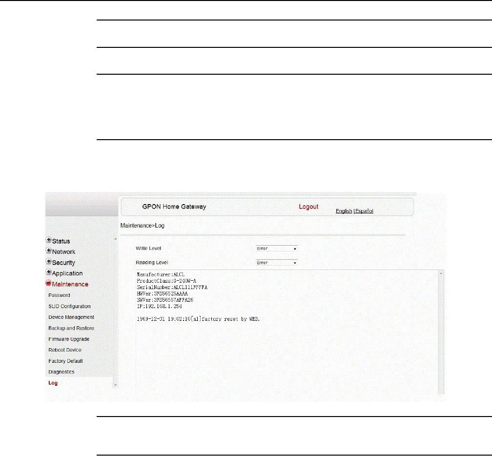
7368 ISAM ONT G-240W-F Product Guide Configure a G-240W-F indoor ONT
Issue: 01 Edition 01 141
9Click Cancel to cancel the test.
10 STOP. This procedure is complete.
Procedure 47 View log files
1Select Maintain > Log from the top-level menu in the GPON Home Gateway window, as
shown in Figure 71.
Figure 71 Log window
2Choose a write level from the drop-down menu to determine which types of events are
recorded in the log file:
3Choose a reading level from the drop-down menu to determine which types of events to
display from the log file:
•Emergency
•Alert
•Critical
•Error
•Warning
•Notice
•Informational
•Debug
DRAFT
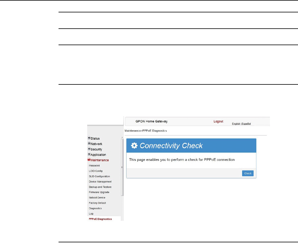
Configure a G-240W-F indoor ONT
142
7368 ISAM ONT G-240W-F Product Guide
Edition 01 Issue: 01
4The log file is displayed at the bottom of the window.
5STOP. This procedure is complete.
Procedure 48 Diagnose PPPoE connections
1Select Maintain > PPPoE Diagnostics from the top-level menu in the GPON Home Gateway
window, as shown in Figure 72.
Figure 72 PPPoE Diagnostics window
2Click Check to view the results for the PPPoE diagnostics, as shown in Figure 73.
DRAFT
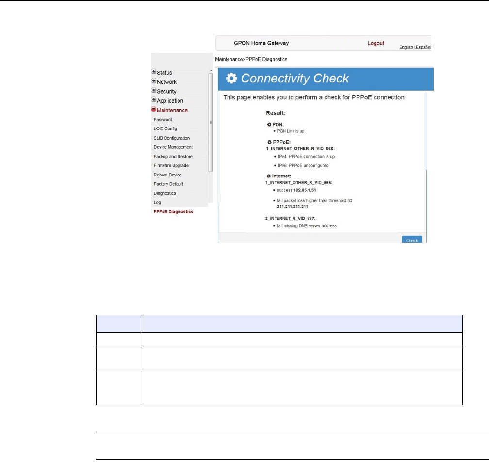
7368 ISAM ONT G-240W-F Product Guide Configure a G-240W-F indoor ONT
Issue: 01 Edition 01 143
Figure 73 PPPoE diagnostics results
Table 51 describes the fields on the PPPoE diagnostics results window.
Table 51 PPPoE diagnostics results parameters
3STOP. This procedure is complete.
8.2.7 RG troubleshooting counters
The Troubleshooting Counters feature enables service providers and end users to
monitor the performance of their broadband connection.
Tests are run to retrieve upstream and downstream throughput, latency, and DNS
response time. The Troubleshooting Counters window also displays upstream and
downstream packet loss and Internet status.
Field Description
PON Reports whether the PON link is up or down
PPPoE Reports whether the PPPoE IPv4 or IPv6 connection is up, connecting, down, not
configured, or not found
Internet For each Internet connection, reports whether the connection succeeded, failed (missing
DNS address), or was not found; also reports failures due to packet loss higher than the
threshold of 30
DRAFT
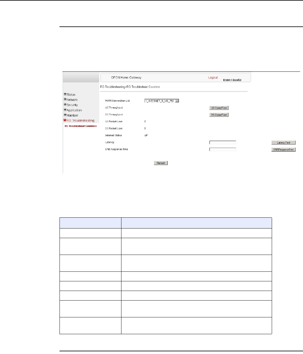
Configure a G-240W-F indoor ONT
144
7368 ISAM ONT G-240W-F Product Guide
Edition 01 Issue: 01
Procedure 49 Retrieve Residential Gateway (RG) troubleshooting counters
1Select RG Troubleshooting Counters from the left menu in the GPON Home Gateway
window.
The RG Troubleshooting Counters window appears; see Figure 74.
Figure 74 RG Troubleshooting Counters window
Table 52 describes the fields in the RG Troubleshooting Counters window.
Table 52 RG Troubleshooting Counters parameters
2Configure the test times if desired.
Field Description
WAN Connection List Select a WAN connection from the list
US Throughput Click US Speed Test to specify the time for the upstream test
The default is weekly, performed at idle to a public server
DS Throughput Click DS Speed Test to specify the time for the downstream test
The default is weekly, performed at idle to a public server
US Packet Loss The number of upstream packages lost
DS Packet Loss The number of downstream packages lost
Internet Status Whether the broadband connections is active (UP) or not (DOWN)
Latency Click Latency Test to specify the time for the test
The default is weekly, performed at idle to a public server
DNS Response Time Click DNS Response Test to specify the time for the test
The default is weekly, performed at idle to a public server
DRAFT

7368 ISAM ONT G-240W-F Product Guide Configure a G-240W-F indoor ONT
Issue: 01 Edition 01 145
3Click Refresh to update the data.
4STOP. This procedure is complete.
8.3 SFU mode GUI configuration
Use the procedures below to utilize the web-based GUI for the G-240W-F in SFU
mode. This mode is preset at delivery.
SFU customer premise devices are designed for single indoor residential
applications. These ONTs address the demand for bandwidth intensive services,
such as high definition television (HDTV), video-on-demand (VOD) and online
games. The ONT can be configured to seamlessly deliver voice-over-IP and high
speed Internet access via a single fiber optic connection to the home.
8.3.1 Login
Use the procedure below to login to the web-based GUI for the G-240W-F.
Procedure 50 Login to web-based GUI
1Open a web browser and enter the IP address of the ONT in the address bar.
The login window appears.
The default gateway IP address is http://192.168.1.254. You can connect to this IP address
using your web browser after connecting your PC to one of Ethernet ports of the ONT. The
static IP address of your PC must be in the same subnet as the ONT.
2Enter your username and password in the Log in window, as shown in Figure 75.
The default username is adminadmin. The default password is ALC#FGU.
DRAFT
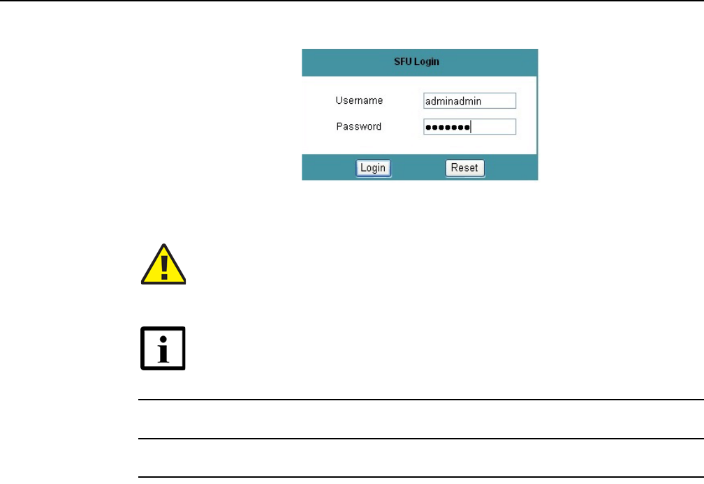
Configure a G-240W-F indoor ONT
146
7368 ISAM ONT G-240W-F Product Guide
Edition 01 Issue: 01
Figure 75 Web login window
3Click Login.
4STOP. This procedure is complete.
8.3.2 Device and connection status
G-240W-F ONTs support the retrieval of a variety of device information.
Caution — Pressing the Reset button for less than 10 seconds reboots
the ONT; pressing the Reset button for 10 seconds resets the ONT to the
factory defaults, except for the LOID and SLID.
Note — If you forget the current username and password, press the
reset button for 10 s and the default values for the username and
password will be recovered at startup.
DRAFT
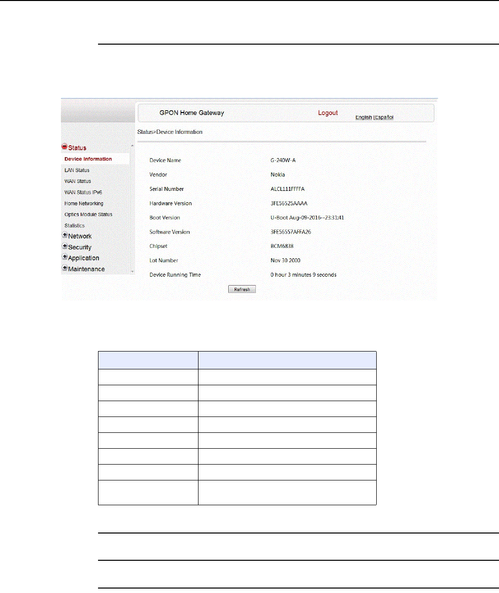
7368 ISAM ONT G-240W-F Product Guide Configure a G-240W-F indoor ONT
Issue: 01 Edition 01 147
Procedure 51 Device information retrieval
1Select Status > Device Information from the top-level menu in the GPON Home Gateway
window, as shown in Figure 76.
Figure 76 Device Information window
Table 53 describes the fields in the Device Information window.
Table 53 Device Information parameters
2Click Refresh to update the displayed information.
3STOP. This procedure is complete.
Field Description
Device Name Name on the ONT
Vendor Name of the vendor
Serial Number Serial number of the ONT
Hardware version Hardware version of the ONT
Boot version Boot version of the ONT
Software version Software version of the ONT
Chipset Chipset of the ONT
Device Running Time Amount of time the device has run since last
reset in hours, minutes, and seconds
DRAFT
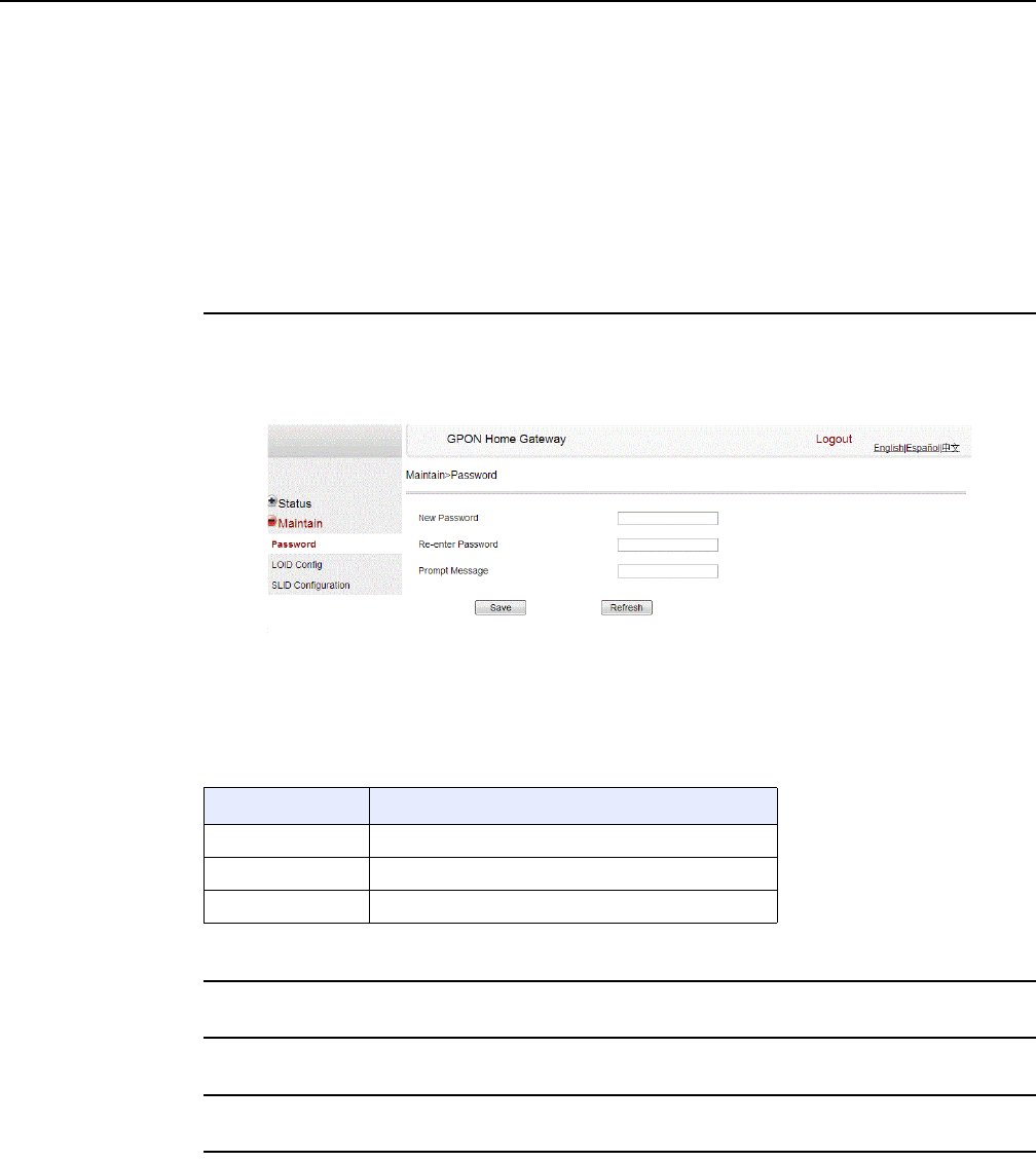
Configure a G-240W-F indoor ONT
148
7368 ISAM ONT G-240W-F Product Guide
Edition 01 Issue: 01
8.3.3 Maintenance
G-240W-F ONT also supports maintenance tasks, including:
•password change
•LOID configuration
•SLID configuration
Procedure 52 Password configuration
1Select Maintain > Password from the top-level menu in the GPON Home Gateway window,
as shown in Figure 77.
Figure 77 Password window
Table 54 describes the fields in the password window.
Table 54 Password parameters
2Configure the new password.
3Click Save.
4STOP. This procedure is complete.
Field Description
New Password New password
Re-enter password Password must match password entered above
Prompt message Password prompt message
DRAFT
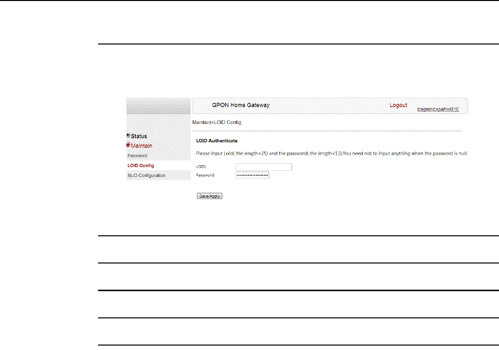
7368 ISAM ONT G-240W-F Product Guide Configure a G-240W-F indoor ONT
Issue: 01 Edition 01 149
Procedure 53 LOID configuration
1Select Maintain > LOID Config from the top-level menu in the GPON Home Gateway window,
as shown in Figure 78.
Figure 78 LOID configuration window
2Enter the LOID.
3Enter the password, if applicable.
4Click Save/Apply.
5STOP. This procedure is complete.
DRAFT
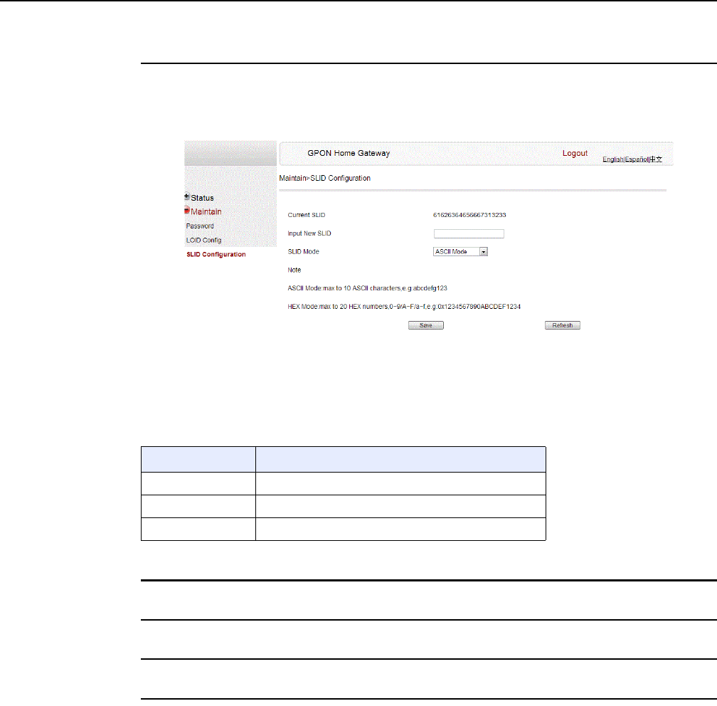
Configure a G-240W-F indoor ONT
150
7368 ISAM ONT G-240W-F Product Guide
Edition 01 Issue: 01
Procedure 54 SLID configuration
1Select Maintain > SLID Configuration from the top-level menu in the GPON Home Gateway
window, as shown in Figure 79.
Figure 79 SLID configuration window
Table 55 describes the fields in the SLID configuration window.
Table 55 SLID configuration parameters
2Configure the new SLID.
3Click Save.
4STOP. This procedure is complete.
8.4 Operator ID
Use the procedure below to modify the operator ID for the G-240W-F.
Field Description
Current SLID Displays current SLID
Input new SLID Enter new SLID
SLID Mode Choose a SLID mode from the drop-down menu.
DRAFT

7368 ISAM ONT G-240W-F Product Guide Configure a G-240W-F indoor ONT
Issue: 01 Edition 01 151
Procedure 55 Modifying the operator ID
1Register the ONT with the OLT.
2Check the original OPID.
3Update the OntConfig.xml file by adding-the following content:
<OperatorObject version=”1.0”>
<OperatorID=”XXXX”>
</OperatorObject>
where: xxxx is the correct operator ID, for example ALCL for HGU mode, or XXXX for SFU mode.
4Use a TFTP client tool to transfer the OntConfi.xml file to the OLT’s ONT directory and
change the filename to the software version number, for example, 3FE123456789.xml.
5Use a TL1 command to configure ONUSWCRTL:
ENT-ONTSWCTRL::1::::HWVER=hwver,VARNT=,PLNDSWVER=UNPLANNED,
PLNDSWVERCONF=UNPLANNED,DLDSWVER=swver;
where:
hwver is the EQPTVERNUM, for example EQPTVERNUM=3FE54945ABAA.
swver is the software version number used as the filename in step 2, for example 3FE123456789.xml.
6Download the .xml file to update the operator ID:
ED-ONT::ONT-1/1/3/1/19::::DLSW=AUTO;
7Restart the ONT, then connect to the LAN and access the web-based GUI to check the
operator ID default setting.
8Use a TL1 command to disable further downloads:
ED-ONT::ONT-1/1/3/1/19::::DLSW=DISABLED;
9STOP. This procedure is complete.
DRAFT

Configure a G-240W-F indoor ONT
152
7368 ISAM ONT G-240W-F Product Guide
Edition 01 Issue: 01
DRAFT

7368 ISAM ONT G-240W-F Product Guide ONT configuration file over OMCI
Issue: 01 Edition 01 153
9 ONT configuration file over OMCI
9.1 Purpose
9.2 Supported configuration file types
9.3 ONT configuration file over OMCI
9.1 Purpose
This procedure describes how to use configuration files over OMCI to configure
ONTs. Some advantages include:
•flexibility to change the ONT default behavior by downloading configuration file
•flexibility to update a deployed ONT by downloading updated parameters
•ability to securely download any configuration file to an ONT
•ability to avoid using embedded configuration files in ONT software
9.2 Supported configuration file types
Table 56 describes the configuration file types that are supported from 7368 ISAM
ONT R05.02.00 and later.
Note — This feature is supported for use with the 7360 ISAM
FX and the 7342 ISAM FTTU.
DRAFT

ONT configuration file over OMCI
154
7368 ISAM ONT G-240W-F Product Guide
Edition 01 Issue: 01
Table 56 Supported configuration files
File Index Description Details Supported ONTs/DPU
PRE ONT
pre-configuration file
The XML-based PRECONFIG file controls the working
mechanics of the ONT for various services. The
default behavior of different ONTs may vary based on
the factory settings.
The pre-configuration file includes the factory default
value for the residential gateway.
Note: the pre-configuration file does not work with SFU
ONTs; therefore, this feature applies only to
Residential Gateway ONTs.
The pre-configuration file can be used as is, but Nokia
provides its customers with the flexibility to customize
the pre-configuration file.
This pre-configuration file enables operators to change
the default behavior by downloading a customized
pre-configuration based on customer inputs.
This PRE XML file includes a custom OPERID.
The Nokia defined index for the PRECONFIG file is:
"PRE"
HGU ONTs:
G-240G-C,G-240W-F,
G-240W-B, G-240W-C
I-240W-A
CFG ONT configuration
delta file
The XML-based CFG file updates the configurable
parameters (the PRE settings) in the existing PRE file
of a deployed ONT, where required.
This configuration file enables operators to change the
deployed behavior by downloading customized
updates in the CFG file.
This file is used only to modify the parameters in the
PRE file; it is not used for service provisioning.
No OPERID is required, because the update is based
on the OPERID used for the PRE file.
The Nokia defined index for the PRECONFIG DELTA
file is: "CFG"
XML Voice XML file The Voice XML file provides an alternate method for
securely downloading voice parameters from the OLT,
rather than using FTP (OMCIv1/OMCIv2) or HTTPS
(TR-069). Downloading this file makes the applicable
changes in the voice parameters.
This file enables operators to change the voice
behavior by downloading the updated voice XML file.
Nokia recommends using this procedure, rather than
embedded voice XML files.
The Nokia defined index for the Voice XML file is:
"XML"
(1 of 2)
DRAFT

7368 ISAM ONT G-240W-F Product Guide ONT configuration file over OMCI
Issue: 01 Edition 01 155
9.2.1 Filename conventions
Nokia provides the raw configuration files, which must be saved by the operator in a
TAR file to be uploaded. TAR file names must be unique.
The filenames of the raw configuration files may not adhere to the naming
conventions outlined below. In this case, the files must be renamed to adhere to the
naming conventions before the operator generates the TAR file. Filenames are not
case-sensitive.
ABCXXXXVER
where
ABC is the file index type (PRE, CFG, XML, GFT)
XXXX is the operator ID
For PRE and CFG, a valid operator ID is required
For XML and GFT, any characters may be used
VER is the file version (from 001 to 999)
Note: you cannot update the configuration using two files with the same name.
9.3 ONT configuration file over OMCI
Use this procedure to configure ONTs using configuration files via OMCI.
GFT G.fast-related
configuration file
This text-based json script file controls the default
behavior of the G.Fast ONT.
This file includes the provisioning parameters of the
G.fast transports layer; it does not include VLAN or
QoS provisioning.
While the ONT functions well with the default values;
they can optionally be customized.
While default values can work in VDSL mode, a
download file is required for the device to function as a
G.fast ONT.
The Nokia defined index for the G.fast file is: "GFT"
HGU ONTs:
G-240G-C,G-240W-F,
G-240W-B, G-240W-C
I-240W-A
File Index Description Details Supported ONTs/DPU
(2 of 2)
Warning — Executing the following procedure will trigger the
ONT to reboot, which will impact ongoing services.
DRAFT

ONT configuration file over OMCI
156
7368 ISAM ONT G-240W-F Product Guide
Edition 01 Issue: 01
Procedure 56 Configuring an ONT using a configuration file via OMCI
1Generate the TAR file to be uploaded to the OLT.
Using the raw configuration file(s) provided by Nokia, generate the TAR file as follows:
iOn a Linux platform, rename the raw configuration file to adhere to the naming
convention, as described in section 9.2.
ii Tar the ABCXXXXVER raw configuration file:
tar -cf ABCXXXXVER.tar ABCXXXXVER
Where
ABCXXXXVER
Is the name of the file created in step i.
This creates two files: ABCXXXXVER and ABCXXXXVER.tar.
iii Rename ABCXXXXVER to ABCXXXXVER.org
iv Remove the “.tar” extension from ABCXXXXVER.tar file.
2Upload the ABCXXXXVER TAR file to the /ONT/ directory in the OLT.
A maximum of 250 files can be kept in the OLT file system.
3Using OLT commands, download the TAR file to the ONT.
For OLT commands, refer to the 7360 ISAM FX CLI Command Guide for 100_320Gbps FD
NT and FX NT, or the 7342 ISAM FTTU Operation and Maintenance Using TL1 and CLI.
Please note:
•pri-cfgfile-pland/dnload or sec-cfgfile-pland/dnload can be 1 to 14
characters.
•pri-cfgfile-pland and pri-cfgfile-dnload should be the same name.
Examples
Note: X can be 1 or 2 unless specified:
iIf pland-cfgfileX= Disabled and dnload-cfgfileX= Disabled ,
no file will be downloaded to the ONT.
ii If pland-cfgfileX=FILENAME1 and dnload-cfgfileX= Disabled ,
FILENAME1 will be downloaded and FILENAME1 will be made active. An ONT reboot
is required.
iii If pland-cfgfileX=Disabled and dnload-cfgfileX= FILENAME2
DRAFT

7368 ISAM ONT G-240W-F Product Guide ONT configuration file over OMCI
Issue: 01 Edition 01 157
FILENAME2 will be downloaded and FILENAME2 will be made passive. An ONT reboot
is not required.
iv If pland-cfgfileX=FILENAME3 and dnload-cfgfileX= FILENAME 4, the OLT
reports an error because the filenames are not the same.
vConfigure equipment interface … pland-cfgfile1=XMLXXXXXX1 and
dnload-cfgfile1 XMLXXXXXX1
Configure equipment interface … pland-cfgfile2=XMLXXXXXX2 and
dnload-cfgfile2 XMLXXXXXX2
Although the OLT permits the above two steps without reporting an error, Nokia does
not recommend executing them, because the ONT may exhibit unexpected behavior.
vi If pland-cfgfileX=Auto and dnload-cfgfileX= Auto
The OLT will download the XML file from "sw-ctr-list" (configure equipment ont
sw-ctrl)
4STOP. This procedure is complete.
The ONT will distribute the configuration files to the different services based on the active
indication from the OLT and on the Nokia defined index.
The ONT automatically reboots to apply the configuration files. After the ONT reboots and reports
the active version, the OLT completes the file download procedure.
Operators must check the committed file from the OLT to verify whether the corresponding file has
been applied. If an error occurs, contact Nokia for support.
DRAFT

ONT configuration file over OMCI
158
7368 ISAM ONT G-240W-F Product Guide
Edition 01 Issue: 01
DRAFT


FCC
Rcgulations
白
lisd
肝
ice
comp
1i国
withpa
此
15
of
the
FCC
Rul~.
Opemtion
is
subject
to
由
efoUo
飞,
v
in
g
two
con
ditioll!l: (1)
Th
is d
e\
'ice
ma
川
.
10t
cause
h
3.n1由
j
interfer
enc
e.
andο)
由
is
dev
ice
mll
st
acc
叩
t
3.
ny
interference
receiv
时
.
includillg
inte
江
ference
th3t
may
ca
u
se
undesired operatioll
1\
0τTI
:
This
equ
ipme.nr
has
b~.n
tested
and
found 10 comply with
the
limits for
é\
Cla
岱
D
digi
tal
dc'
飞咀
e
.
purSllant to part
15
nC
山
c
F
r.r:
Rul
出
Th<:."ωlim
iL
'i
an;
Ù
出
I
g
商巳
J
1.
0 prnviùe
rCß~
(J
nllhl
c pr
【
1
l.c
cL
J(
ln
况且
撞
inst
hH.
π
nf
Ll
l
intcrfcr
c
n
ιc
ma
rc
si
ù
i.:
nütl
l i
Il$
l
tlllaLÌuD
,
Thi:>叫
uipmcnt
g
i..
ncralc~.
u
:)cs
a
ml
c
an
nulialc ra
ùi
o f
rr.
:qU
l.:
DCY
cncrgy
lin
J
,>
f n
Ql
in~li
:1l
kù
an
i.l
US
i:ld
in
ucωrùanc;:
wi
由由<:
lßslru
l,:
tlons.
rn
均
CUU:H::
hurmful
int
也
r
.fi旨
在
~nCd
lO
faù
io
I,;
omm
咀
ic
u
Li
o
n
s
,
Hοw<:v
~r
.
th~r
t::
is
no
guara
nt
ee
that
int
回
erence
will
l1
0t
OCC~l
r
in
3.
?3.
rtic
ul
ar
ul
stJ
ll
Jtio
ll
.
Ifthis
明
uipment
d
。因
C
<l1.l
se
h
<l
nntul
in
te
rf
eren
ce
to
rad
io
or
t
el
e\-
<ision
r
ec
酬
1
0
阻>
which can
be
de
te
nn
ined
by
tuming
the
叫
u
ipment
o
ff
an
d
on
, the user is
enCO
ll
li1
ged
to
t
巧'
to
co
rrect t
he
interference
by
o
ne
or
more
oft
he following
me
as
ur
e,
s
-
R 山
l
TH
':
ηL
nr
rc
h
>l:
al
i.:
t.
h
i.:
rc
t.:川、.'
1n
g
抱
ntcn
n
抽
.y
ncrC&
::I
C rhc
~cpllr8tion
hm
认
c
c
n
t
hc
equipmcnt
and
r
,国
C
l
vc
r
巳
01111
配
t
rhe
eq
llipment
i11to
an
omJet
on
a c
ir
cuit
dift
'e
rell
t
丘咀
1
that
ro
\\'hich
the
receiver
is
connected
-C
O
!l5
u
1t
由
e
dealer
or
nn
expe.rienced
radio:'
TV
technÎcÎs
Jl
for h
elp
口
h
,
"吕出Ilr
m(
叫
ifi
t.:
ati
o n
:-l
nnL
l!
xp
ri.!. ...
'l
ly
appmνcù
hy
lh
>
manufacLun.
:r
cllu
ld
Vllid
Lh
c
uscr
、
a
uth
ori
t.
y
t.1l
opc
r
ll.
t
i.!
th
c
、飞
U
l
pmcnt
FCC
RF
Radiatioll
Exposure
Statement
Thi
s
呵
llipment
compl
ie
s
\,
'ith
ν
巳巳且
.
1-'
radiarion
阻
p
osure
li
Dl
irs
se
t.
fo
rth
fo
r
<l.
n
un
controlled e.mironme
ll
t.
This devi
ce
and
it
s
ante
.n
na
ml
lst not
be
co~lo('.a
t
e.d
or
op
盯
'
an
n
g
m
con
Ju
nctlon
飞气
l
ith
any
other anrenna
or
transmitter
"
To
comply
with
r:
rx:
Rf
e
又
posure
co
mp
1i
ance
r
equ
ir
emen
饵.
t
hi::;
grant
i::;
叩
plicah
l
e
10
on
ly Mohile Configura
ti
ons. The
II.
nt
c:
nn
剧lJ
~OO
ror
lhi~
tr
ll.
n
!t
m
in
叮
mu
业
hc
in
!tlH
llcu
10
pmviu
\C也吨,,,由
on
ùi
想l<"巳巳
o
f
川
10
剧
t
20
cm
rrom
驰lI
p
t:啊
m
sa
n
ù
mU5t
not
bð
co-locntçd 0
1'
oþðrating
in
conju
且由
onW1
由
any
0
由-e1'
antennil
or
tr
nnsmitter
,"