Nokia Networks R240-V01 FHSS ODU and IDU User Manual NRWR guide v4
Nokia Networks Inc FHSS ODU and IDU NRWR guide v4
Contents
- 1. Users Manual
- 2. User Installation
- 3. End User Manual
- 4. Professional installation
Professional installation

WRTS38591.01, version 1.0
April, 2001
Nokia RoofTop™ Wireless Router
(R240/ R240A) Hardware
Installation Guide

COPYRIGHT
© 2000 Nokia Corporation. All rights reserved.
Rights reserved under the copyright laws of the United States.
RESTRICTED RIGHTS LEGEND
Use, duplication, or disclosure by the Government is subject to restrictions as set forth in subparagraph (c)(1)(ii) of the Rights in
Technical Data and Computer Software clause at DFARS 252.227-7013.
IMPORTANT NOTE TO USERS
This device has been certified as an intentional radiator (transmitter) which requires that it is installed and/or moved by
a trained professional.
TRADEMARKS
Nokia is a registered trademark of Nokia Corporation. Nokia RoofTop™ is a registered trademark of Nokia Networks.
Other products mentioned in this document are trademarks or registered trademarks of their respective holders.
COMPLIANCE STATEMENTS
This hardware complies with the standards listed in this section.
Compliance in the United States
Emission Standards
UNINTENTIONAL EMISSIONS: FCC Part 15 CLASS B
INTENTIONAL EMISSIONS: FCC Part 15, Section 15.247
This equipment has been tested and found to comply with the limits for a Class B digital device, pursuant to Part 15 of the FCC
rules. These limits are designed to provide reasonable protection against harmful interference in a residential installation. This
equipment generates, uses, and can radiate radio frequency energy and, if not installed and used in accordance with the instruc-
tions, may cause harmful interference to radio communications. However, there is no guarantee that interference will not occur
in a particular installation. If this equipment does cause harmful interference to radio or television reception which can be deter-
mined by turning the equipment off and on, the user is encouraged to try and correct the interference by one or more of the fol-
lowing measures:
—Reorient or locate the receiving antenna.
—Increase the separation between the equipment and receiver.
—Connect the equipment into an outlet on a circuit different from that to which the receiver is connected.
—Consult the dealer or an experienced radio/TV technician for help.
Any modifications made to the unit, unless expressly approved by Nokia could void the user’s authority to operate the equip-
ment.

FCC Rules and Regulations - Part 68
This equipment complies with Part 68 of the FCC Rules. The FCC Part 68 Label is located on the rear panel of the Network/
Power Unit. This label contains, among other information, the FCC Registration Number and Ringer Equivalency Number (REN)
for this equipment. You must, upon request, provide this information to your telephone company. The REN is useful to determine
the quantity of devices you may connect to your telephone line and still have all those devices ring when your telephone number
is called. In most but not all areas, the sum of the RENs of all devices connected to one line should not exceed five (5.0). To be
certain of the number of devices you may connect to your line, as determined by the REN, you should contact your local tele-
phone company to determine the maximum REN for your calling area.
Connection to the telephone network should be made by using standard modular telephone jacks, type RJ11. The plug and/or
jacks used must comply with FCC Part 68 rules. If your telephone equipment causes harm to the telephone network, the
telephone company may discontinue your service temporarily. If possible, they will notify you in advance, but if advance notice is
not practical, you will be notified as soon as possible. You will be informed of your right to file a complaint with the FCC.
Your telephone company may make changes in its facilities, equipment, operations or procedures that could affect the proper
functioning of your equipment, If they do, you will be notified' in advance to give you an opportunity to maintain uninterrupted
telephone service.
This equipment may not be used on coin service provided by the telephone company. Connection to party lines is subject to
tariffs.
If trouble is experienced with this unit, for repair or warranty information, please contact customer service at the address and
phone listed below. If the equipment is causing harm to the network, the telephone company may request that you disconnect
the equipment until the problem is resolved.
DO NOT DISASSEMBLE THIS EQUIPMENT. It does not contain any user serviceable components.
Compliance in Canada
Canadian compliance (Industry Canada) When tested with at least one intended host: This digital apparatus does not exceed
the Class B limits for radio noise emissions from digital apparatus set out in the interference-causing equipment entitled "Digital
Apparatus", ICES-003 of the Canadian Department of Communications.
Cet appareil numérique respecte les limites bruits radioélectriques applicables aux appareils numériques de Class B prescrites
dans la norme sur le matériel brouilleur: "Appareils Numériques", NMB-003 édictée par le Ministre Canadien des Communica-
tions.
Notice: The Industry Canada (IC) label identifies certified equipment. This certification means that the equipment meets tele-
communications network protective, operational and safety requirements as prescribed in the appropriate Terminal Equipment
Technical document(s). The department does not guarantee the equipment will operate to the user's satisfaction.
Before installing this equipment, users should ensure that it is permissible to be connected to the facilities of the local telecom-
munications company. The equipment must also be installed using an acceptable method of connection. The customer should
be aware that compliance with the above conditions may not prevent degradation of service in some situations.
Repairs to certified equipment should be coordinated by a representative designated by the supplier. Any repairs or alterations

made by a user to this equipment, or equipment malfunctions, may give the telephone communications company cause to
request the user to disconnect the equipment.
The installer should ensure that the electrical ground connections of the power utility, telephone lines and internal metallic water
pipe system, if present, are connected together. This precaution may be particularly important in rural areas.
Caution: Users should not attempt to make such connections themselves, but should contact the appropriate electric inspection
authority, or electrician, as appropriate.
Notice: The Ringer Equivalent Number (REN) assigned to each terminal device provides an indication of the maximum number
of terminals allowed to be connected to a telephone interface. The termination on an interface may consist of any combination of
devices subject only to the requirement that the sum of the Ringer Equivalence Numbers of all the devices does not exeed 5.
REN: See the equipment for REN information.

DISCLAIMER:
TO THE INSTALLER: THE INSTRUCTIONS PROVIDED IN THIS GUIDE ARE PROVIDED “AS IS” WITHOUT WARRANTY OF
ANY KIND EXPRESSED OR IMPLIED. NOKIA MAKES NO REPRESENTATIONS OR WARRANTIES, EXPRESSED OR
IMPLIED, INCLUDING BUT NOT LIMITED TO THE WARRANTIES OF MERCHANTABILITY OR FITNESS FOR A PARTICU-
LAR PURPOSE OR INFRINGEMENT, INCLUDING ANY THIRD PARTY PATENTS, COPYRIGHTS, TRADEMARKS OR
OTHER RIGHTS. THERE IS NO WARRANTY BY NOKIA THAT THE INSTRUCTIONS CONTAINED IN THE GUIDE WILL
MEET YOUR REQUIREMENTS. THERE IS NO WARRANTY BY NOKIA THAT THE INSTRUCTIONS AND STATEMENTS
CONTAINED IN THE GUIDE OR ITS CONTENT ARE TRUE, ACCURATE OR COMPLETE.
LIMITATION OF LIABILITY: TO THE MAXIMUM EXTENT PERMITTED BY APPLICABLE LAW, IN NO EVENT SHALL NOKIA,
ITS EMPLOYEES OR AFFILIATES BE LIABLE FOR ANY LOST PROFITS, REVENUE, SALES, DATA, OR COSTS OF PRO-
CUREMENT OF SUBSTITUTE GOODS OR SERVICES, PROPERTY DAMAGE, PERSONAL INJURY, INTERRUPTION OF
BUSINESS, LOSS OF BUSINESS INFORMATION OR FOR ANY SPECIAL, DIRECT, INDIRECT, INCIDENTAL, ECONOMIC,
COVER, PUNITIVE, SPECIAL OR CONSEQUENTIAL DAMAGES HOWEVER CAUSED, AND WHETHER ARISING UNDER
CONTRACT, TORT, NEGLIGENCE, OR OTHER THEORY OF LIABILITY ARISING OUT OF THE USE OF OR INABILITY TO
USE THE GUIDE, EVEN IF NOKIA OR AFFILIATES ARE ADVISED OF THE POSSIBILITY OF SUCH DAMAGES.


Contents
CHAPTER 1 About this document . . . . . . . . . . . . . . . . . . . . . . . . . . . 1
1.1 Introduction . . . . . . . . . . . . . . . . . . . . . . . . . . . . . 1
1.1.1 Components of the Wireless Router. . . . . . . . . . . 2
1.1.2 Overview of the installation . . . . . . . . . . . . . . . . . 2
CHAPTER 2 Safety issues . . . . . . . . . . . . . . . . . . . . . . . . . . . . . . . . . . . . 5
2.1 Introduction . . . . . . . . . . . . . . . . . . . . . . . . . . . . . 5
2.1.1 Hazard warnings. . . . . . . . . . . . . . . . . . . . . . . . . . 6
CHAPTER 3 Site survey . . . . . . . . . . . . . . . . . . . . . . . . . . . . . . . . . . . . . . 7
3.1 Introduction . . . . . . . . . . . . . . . . . . . . . . . . . . . . . 7
3.2 Determining the RF links to other sites. . . . . . . . 8
3.3 Surveying potential sites . . . . . . . . . . . . . . . . . . . 9
3.3.1 Line of sight analysis . . . . . . . . . . . . . . . . . . . . . . 9
3.4 Selecting the antenna type . . . . . . . . . . . . . . . . . 11
3.4.1 Omnidirectional antennas. . . . . . . . . . . . . . . . . . 11
3.4.2 Directional antennas . . . . . . . . . . . . . . . . . . . . . . 11
CHAPTER 4 Planning the installation . . . . . . . . . . . . . . . . . . . . . . 13
4.1 Introduction . . . . . . . . . . . . . . . . . . . . . . . . . . . . 13
4.2 Planning . . . . . . . . . . . . . . . . . . . . . . . . . . . . . . . 14
4.2.1 Gathering the tools . . . . . . . . . . . . . . . . . . . . . . . 14
4.2.2 Finding a location for the router. . . . . . . . . . . . . 14
4.2.3 Finding a location for the NPU . . . . . . . . . . . . . 15
4.2.4 Planning the cable routing . . . . . . . . . . . . . . . . . 15
4.2.5 Finding a location for the grounding . . . . . . . . . 15
CHAPTER 5 Installing the outdoor components . . . . . . . . . . . 17
5.1 Introduction . . . . . . . . . . . . . . . . . . . . . . . . . . . . 17
5.1.1 Components to be installed . . . . . . . . . . . . . . . . 18

Contents
5.2 Installing the wireless router with an integral
antenna . . . . . . . . . . . . . . . . . . . . . . . . . . . . . . . 19
5.3 Installing the directional antenna. . . . . . . . . . . . 26
5.4 Grounding the router . . . . . . . . . . . . . . . . . . . . . 32
CHAPTER 6 Installing the indoor components . . . . . . . . . . . . 34
6.1 Introduction . . . . . . . . . . . . . . . . . . . . . . . . . . . . 34
6.1.1 The Network/ Power Unit (NPU). . . . . . . . . . . . 35
6.2 Connecting the multiwire cable. . . . . . . . . . . . . 36
6.3 Identifying LED status. . . . . . . . . . . . . . . . . . . . 41
6.4 Connecting to the computer. . . . . . . . . . . . . . . . 44
6.4.1 Direct personal computer connection. . . . . . . . . 44
6.4.2 Phoneline networking connection . . . . . . . . . . . 45
6.4.3 Network connection . . . . . . . . . . . . . . . . . . . . . . 48
CHAPTER 7 Configuring the PC . . . . . . . . . . . . . . . . . . . . . . . . . . . 50
7.1 Introduction . . . . . . . . . . . . . . . . . . . . . . . . . . . . 50
7.1.1 Configuring the personal computer . . . . . . . . . . 51
CHAPTER 8 Post installation testing . . . . . . . . . . . . . . . . . . . . . . . 52
8.1 Introduction . . . . . . . . . . . . . . . . . . . . . . . . . . . . 52
8.1.1 Testing . . . . . . . . . . . . . . . . . . . . . . . . . . . . . . . . 53
APPENDIX A Cables . . . . . . . . . . . . . . . . . . . . . . . . . . . . . . . . . . . . . . . . . 54
APPENDIX B Technical specifications . . . . . . . . . . . . . . . . . . . . . 56
APPENDIX C Regulatory safety requirements . . . . . . . . . . . . . 60

Nokia RoofTop™ Wireless Router Installation Guide 1
CHAPTER 1 About this document
1.1 Introduction
This document explains the procedures necessary to install the Nokia
Rooftop Wireless Router. It also covers important information about the
router, from selecting its installation site to connecting it to the computer.
This chapter gives you an overview of the installation process.
2 Nokia RoofTop™ Wireless Router Installation Guide
1.1.1 Components of the Wireless Router
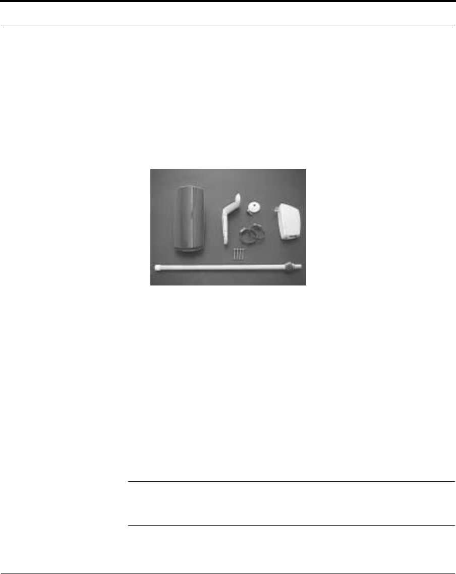
The Nokia Rooftop Wireless Router consists of the following
components:
•a router with integral antenna
•router mounting hardware
•a Network/Power Unit (NPU)
•a multiwire cable which is necessary for connection between the
router and the NPU. The cable is not included in the package because
its length must be specified. Nokia provides numerous lengths of
cable.
1.1.2 Overview of the installation
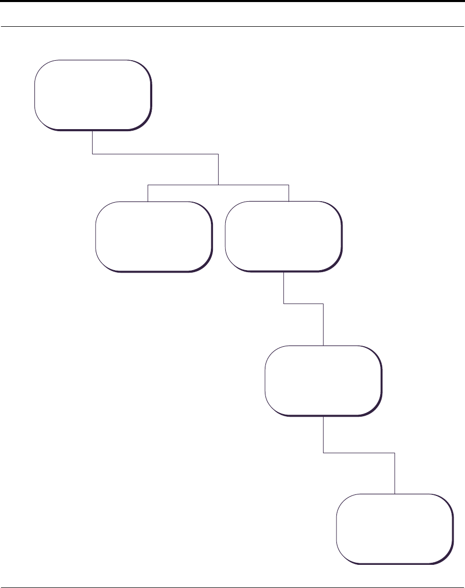
The following flowchart shows an overview of the tasks you will
complete during installation. Follow the chart sequence and the
instructions provided in the chapters to complete the installation.
NOTE: The Nokia RoofTop Wireless Router has to be preconfigured by
an Internet Service Provider prior to installation. If the router has not been
preconfigured, it will not work properly.
Nokia RoofTop™ Wireless Router Installation Guide 3
Introduction
P l a n n i n g
- s i t e s e l e c t i o n
- r o u t e r l o c a t i o n
- c a b l i n g
- r o u t e r p r e p a r a t i o n
- r o u t e r a t t a c h m e n t
- c a b l e r o u t i n g
I n s t a l l i n g o u t d o o r
c o m p o n e n t s
- N P U c o n n e c t i o n
- c o m p u t e r c o n n e c t i o n
I n s t a l l i n g i n d o o r
c o m p o n e n t s
- I P a d d r e s s a s s i g n m e n t
C o n f i g u r i n g
p e r s o n a l c o m p u t e r
T e s t i n g
- L E D c h e c k
- I n t e r n e t a c c e s s c h e c k

4 Nokia RoofTop™ Wireless Router Installation Guide

Nokia RoofTop™ Wireless Router Installation Guide 5
CHAPTER 2 Safety issues
2.1 Introduction
When installing the Nokia Wireless Router, it is important that the unit is
not installed where it could be damaged by the environment or pose a
hazard to the user. Be aware of the safety regulations described in this
chapter.
This chapter lists safety considerations you should understand before you
move on to installation.

6 Nokia RoofTop™ Wireless Router Installation Guide
2.1.1 Hazard warnings
•Environment - The Network/Power Unit (NPU) is an electrical
device. Place it away from all heat sources such as radiators, heat
registers, stoves, amplifiers and other heat producing appliances. It
should also be kept out of cold, dusty, wet, or high humidity areas.
• Fire or electric shock - Keep the NPU away from moisture or water-
related environments such as sinks, bathtubs, laundry areas, spas,
swimming pools, or wet basements. Take care not to spill any liquid
on the unit.
• Installation - Outdoor antennas and their supporting masts, wires,
and cables are electrical conductors. Use extreme caution when
installing antennas in areas with overhead power lines. Contact with
high-voltage electrical wires can cause serious injury or death.
• Medical devices - If you have a pacemaker do not go close to the
router on the roof. If you have any discomfort, switch off the router
immediately.
• Lightning - Routers are elevated metal objects and they attract
lightning and are subject to voltage surges and built-up static charges.
Make sure the router and antenna are attached to a grounding wire to
to provide a safe path to the ground.
•Interference - The router can cause electrical interference. Do not
install the router near medical equipment or in a hospital or medical
environment without first ensuring that there will be no interference
with such equipment.
• Co-located antennas - Up to six sector antennas or three omni-
directional antennas may be co-located provided that they are
permanently mounted on a rooftop or antenna tower where access to
the general public is restricted. In order to comply with FCC RF
safety regulations, antennas shall be placed at least 1 meter (3 feet)
apart. The warning sticker provided with the equipment has to be
attached on the co-located devices.
• RF Exposure - The system shall be permanently mounted on a
rooftop or antenna tower. To comply with FCC RF safety
requirements , always disconnect power from the wireless router
whenever working within 20cm of the antenna. When the RF adapter
is used, only Nokia approved antennas may be used.

Nokia RoofTop™ Wireless Router Installation Guide 7
CHAPTER 3 Site survey
3.1 Introduction
The goals of a site survey are to determine the feasibility of RF links at
each site and to determine the antenna and cable requirements. While a
survey is performed by the Internet Service Provider (ISP) prior to
installation, it is helpful to understand how a site and antenna are selected.
This chapter discusses issues that are considered while choosing a site and
type of antenna.

8 Nokia RoofTop™ Wireless Router Installation Guide
3.2 Determining the RF links to other sites
The feasibility of an RF link can be estimated based on:
•Distances between potential sites
•Line of sight for RF paths
•Antenna RF gains
•Cable and connector losses
If the site has good links to other sites, it can be used as a forwarding
system for other wireless routers in the network. If the router can link to
one other router, it will be able to access the internet, but it will be unable
to forward signals to other wireless routers. If it can link to more than one
router, it can share many more signals in many directions. Nokia
recommends that each router has three hops or less to the AirHead.
Determine the RF path between the antenna at the site and the antennas at
other, adjacent sites. For a directional link with a single antenna, there is
only one RF path. For an omnidirectional antenna, determine all RF
paths. The RF path can be determined by knowing the relative bearing
from the current site to adjacent sites.

Nokia RoofTop™ Wireless Router Installation Guide 9
Surveying potential sites
3.3 Surveying potential sites
Wherever possible, find a site that is unobstructed for some distance. This
ensures maximum connectivity and allows the system to forward
“packets” of information for existing and future needs.
3.3.1 Line of sight analysis
In order for the Nokia Wireless Router network to operate correctly, there
must be line of sight paths for each link.
Determine that there is a visual line of sight and a radio line of sight
between the router to be installed and its neighboring routers.
It is recommended that each router has a line of sight to at least 2 other
routers to enable several options to route internet traffic to the AirHead.
Visual line of sight
Visual line of sight exists when an imaginary straight line can be drawn
between two antennas without passing through any physical obstructions.
Verifying visual line of sight is the first step in planning the Nokia
Wireless Router System installation. Observation points must be high
enough to allow the viewer to see over ground based obstructions.
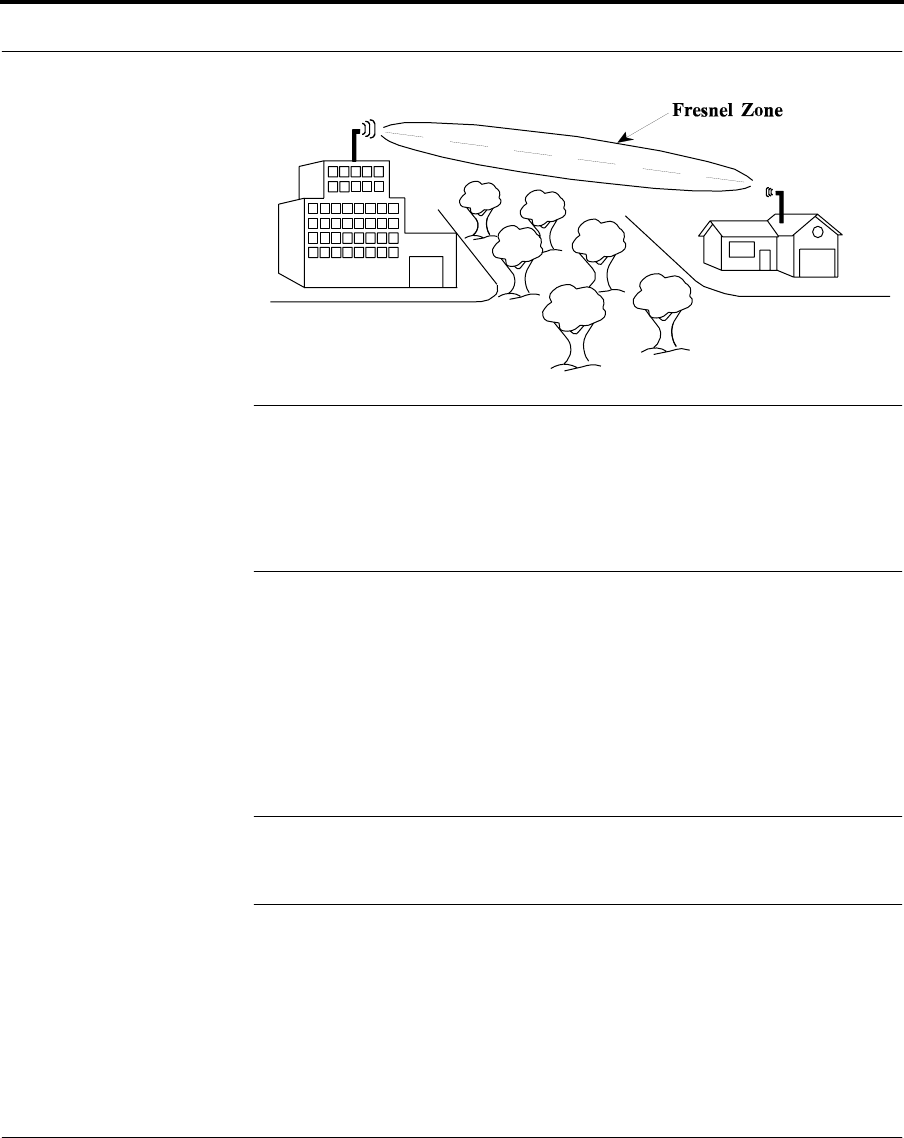
Radio line of sight
A radio wave is not like a laser with a narrow, pointed beam. RF waves
fan out from a single source and are diffracted or absorbed by objects that
are near the visual line of sight. This area is called the Fresnel Zone. Clear
radio line of sight exists when there are no physical obstructions in the
Fresnel Zone. It is therefore essential that there is a clear radio path by
raising the antenna as high as possible and away from objects near the
radio path.
10 Nokia RoofTop™ Wireless Router Installation Guide
NOTE: An example of the Fresnel Zone dimensions is, for a one quarter
mile link, the Fresnel Zone is approximately 71/2 feet above and below
the line of site. Therefore the height of the antenna must clear the Fresnel
Zone. For very short distances, wooden structures and non metallic
objects have little effect on the RF signal. For long distance paths, there
should be no obstacles close to the RF path.
To determine line of sight
1. Access the rooftop using a safe ladder, either tied or held by another
surveyor.
2. Scan the other rooftops in the location. Ensure line of sight ensuring
that other routers can be seen from the selected vantage point.
NOTE: The router being installed may be the first in the area. If this is the
case, ensure that the other rooftops in the area can be seen from the
selected vantage point.
3. If it is not possible to see other routers/rooftops, it may be necessary
to install the router on an adjoining tall structure, or to install a mast.
Nokia RoofTop™ Wireless Router Installation Guide 11
Selecting the antenna type
3.4 Selecting the antenna type
The Nokia Rooftop Wireless Router is supplied with an omnidirectional
antenna. For very specific cases, however, it may be necessary to use a
directional antenna. The following explanations describe the two types of
antenna and the special circumstances in which the directional antenna
may be used.
3.4.1 Omnidirectional antennas
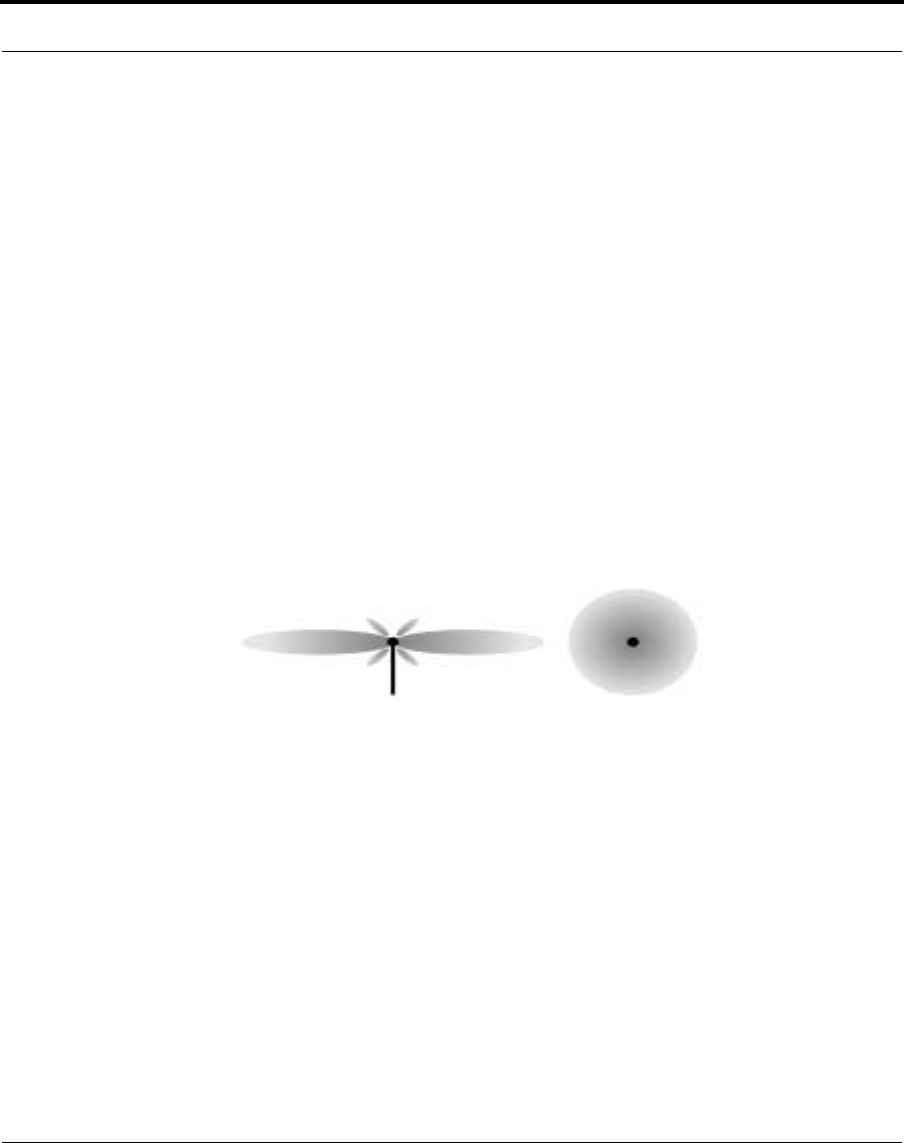
Omnidirectional antennas radiate their RF pattern spherically, providing
coverage in all directions. These are best suited for multipoint links and
are used at all forwarding sites.
Omnidirectional antennas are the preferred solution to most installations.
Omnidirectional Antenna - RF Radiation Pattern
3.4.2 Directional antennas
Directional antennas focus the RF beam in narrow patterns in one
direction and provide communication over greater distances than
omnidirectional antennas, but they are limited in the areas they cover.
Directional antennas are useful for long distance or point-to-point
contacts, but prevent future growth of the network, by preventing the
wireless router from repeating signals to other units. They should be used
only when an omnidirectional antenna will not work.
Top ViewSide View

12 Nokia RoofTop™ Wireless Router Installation Guide
Directional antennas - radiation pattern side view
In Nokia Wireless Router Networks, use a directional antenna only if:
•There are numerous obstructions in the area
•The nearest router is a considerable distance away
•The router is in a location where it does not need to route traffic for
other subscribers and itself requires a maximum link distance to the
neighboring router.
•There are more than two AirHeads co-located at one site

Nokia RoofTop™ Wireless Router Installation Guide 13
CHAPTER 4 Planning the installation
4.1 Introduction
Before you begin the installation, spend some time planning the
process.You need to consider your outdoor environment and your indoor
computer space. This chapter offers suggestions for your planning.

14 Nokia RoofTop™ Wireless Router Installation Guide
4.2 Planning
Consider the following things in your planning:
•Make sure you have the necessary tools.
•Find a safe location for the router, away from power lines and near a
ground.
•Find a safe and optimal location for the NPU, either near the
computer if you are connecting to only one system, or in an out-of-
the-way place if you are connecting several systems.
•Plan the cable routing to minimize the length of cable and
environmental problems. (See chapter 2, “Safety issues” for more
information).
•Find a location for the grounding.
•Review the rest of this guide.
•Ensure that co-located antennas will be placed at least 1 meter (3 feet)
apart.
4.2.1 Gathering the tools
You will find a list of tools in Appendix D. In addition you will need
either a RJ-11 phone cable (if HomePNA is used), patch cable or Ethernet
cross-over cable.
4.2.2 Finding a location for the router
When looking for the location of the router, consider the following things:
•Use an existing structure on the top of the house, for example, a
chimney, vent, or television antenna.
•Use a mounting pole only if there is no other existing high point.
•Wherever you position the router, place it as high as you can. In all
cases, be sure the router is higher than the roof line.

Nokia RoofTop™ Wireless Router Installation Guide 15
Planning
4.2.3 Finding a location for the NPU
The Network/ Power Unit is plugged into a grounded AC outlet. When
locating the AC outlet consider the following:
•Try to find a place in close proximity to the place where the multiwire
cable enters the house.
4.2.4 Planning the cable routing
The multiwire cable runs from the outside of the house to the inside so be
aware that outside weather plays a factor. The maximum length of the
multiwire cable that Nokia provides is 150ft. In any case the cable should
be routed so that the length of the cable is minimized.
•Where possible, route the cable inside wall or roof spaces. Try to
avoid drilling holes through the wall.
•Avoid air ducts, water, and gas pipes.
•Where wires have to be routed outside the building, make sure they
are supported with cable clips at 18 to 24 inch intervals.
•Seal any drill holes in the wall using silicone sealant.
•If HomePNA is used, the cable can enter the house anywhere, where
it is close to a phone jack. This will allow you to shorten the distance
you have to route the cable. HomePNA uses the existing phone lines
in the house, so when considering the entrance of the cable or the
location of the NPU, you only need to make sure that they are close to
a phone jack.
4.2.5 Finding a location for the grounding
Test the existing grounding at the property.
•Try to find an electrical ground close to the cable entrance.

16 Nokia RoofTop™ Wireless Router Installation Guide

Nokia RoofTop™ Wireless Router Installation Guide 17
CHAPTER 5 Installing the outdoor components
5.1 Introduction
The first step in the wireless router installation is setting up, placing, and
grounding the router. If you have not already reviewed the information in
chapter 2, “Safety issues” and chapter 4, “Planning the installation”, it is a
good idea to do so.
This chapter provides step-by-step instructions for assembling the router
with an integral antenna and a router with a directional antenna. It also
describes how to ground them.
NOTE: The sequence of steps presented below shows one way of doing
the installation. The actual sequence in which the installation is done may
vary in each installation.

Nokia RoofTop™ Wireless Router Installation Guide 18
Introduction
5.1.1 Components to be installed
The Outdoor portion of the Nokia RoofTop Wireless Router system
includes:
•a wireless router with integral (omnidirectional) antenna
•a grounding kit for router (if required)
•router mounting hardware
•a shielded multiwire cable. Nokia provides several different lengths
of cable with D-Connectors already installed to the end of the cable.
5.1.1.1 Components for the non-integral antenna
If you are installing a router system with a non-integral (directional)
antenna, you need:
•a sector antenna kit, Nokia code WRTT38587.00
Nokia RoofTop™ Wireless Router Installation Guide 19
Installing the wireless router with an integral antenna
5.2 Installing the wireless router with an integral
antenna
There are two basic steps to installing the outdoor components:
•constructing the mounting and
•assembling the router and antenna.
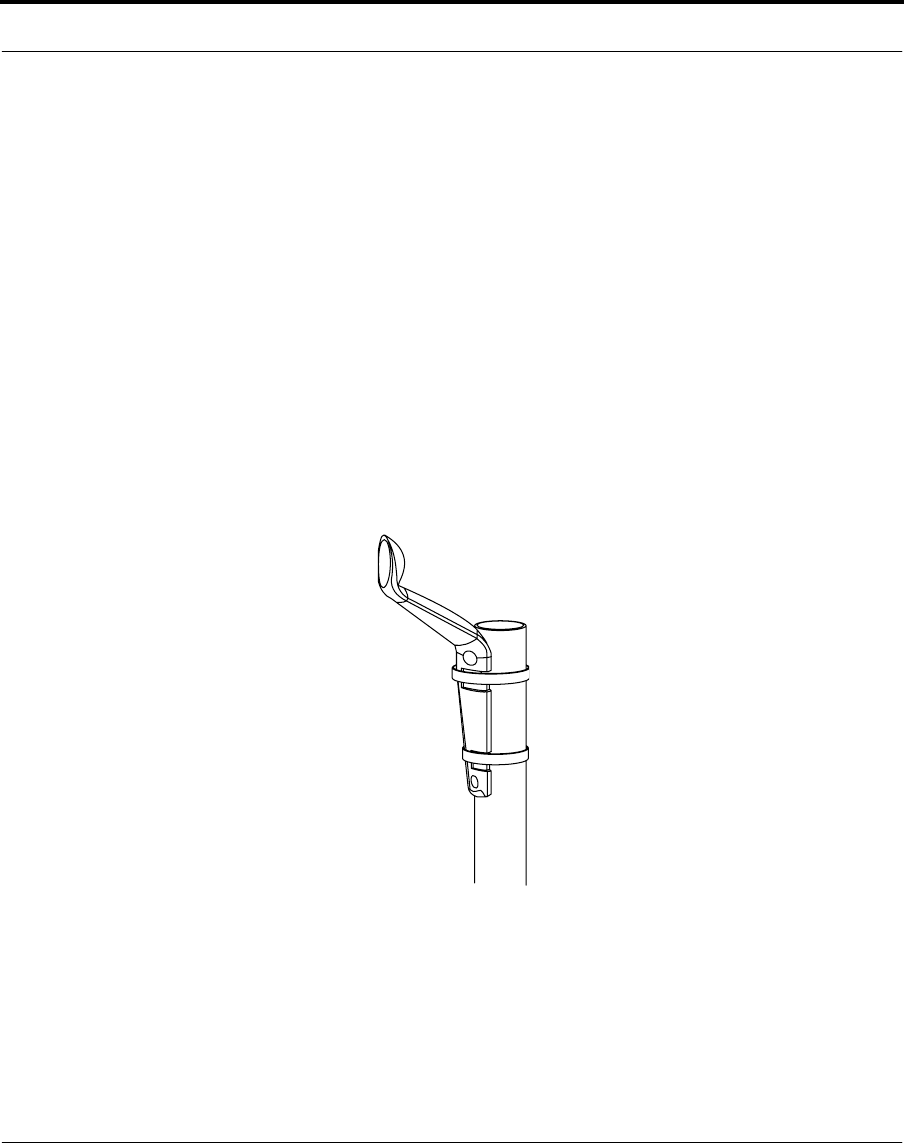
To construct the mounting:
1. Mount the wireless router bracket to the mounting point (it can be a
pole, chimney, vent pipe, etc.), ensuring that the bracket is fixed
securely.
Router bracket fixed to mast

Nokia RoofTop™ Wireless Router Installation Guide 20
Installing the wireless router with an integral antenna
To assemble the router and integral antenna:
The wireless router is packaged with its cover on. To be able to mount it
and to connect the D-connector, you need to remove the cover. To remove
the cover, place your fingers inside the router where the D-connector
connection is located. You can feel the latch that is holding the cover.
Release the latch and lift up the cover.
Now you can go on to assembling the router and antenna.
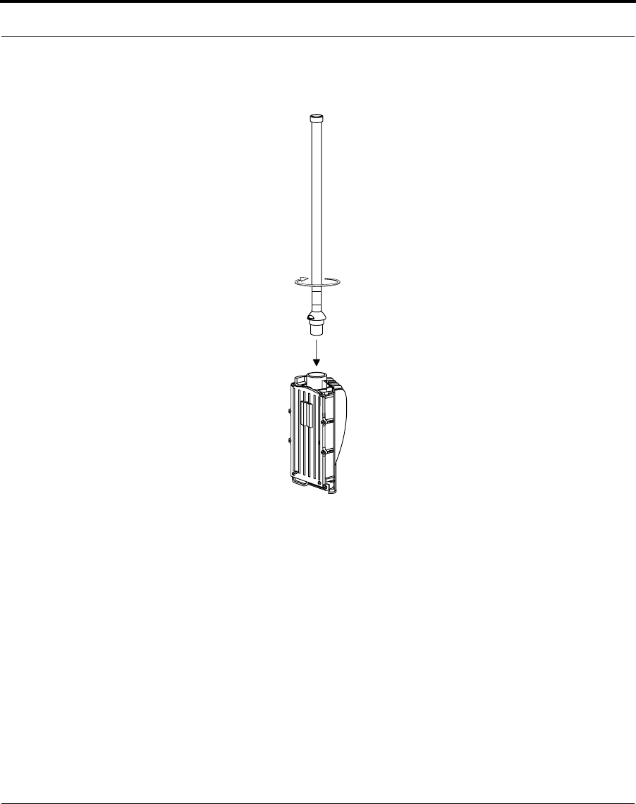
1. First apply silicone lubricant on the threads of the antenna to keep it
from getting jammed. The recommended lubricant is: Dry Lubricant
PRF Tefsol.
•Spray silicone on a rag.
•Wipe the threads of the antenna with the rag.
NOTE: Do not spray silicone directly on the threads. Only a thin coating
of silicone on the threads is needed and spraying them directly would
result in too much silicone on the threads.
2. Attach the omnidirectional antenna by screwing it into the top of the
wireless router.
Nokia RoofTop™ Wireless Router Installation Guide 21
Installing the wireless router with an integral antenna
Ensure secure connection by hand-tightening metal-to-metal. The
tightening torque should not exceed 13 ft./lb. (18Nm).
Attach the omni-directional antenna
Nokia RoofTop™ Wireless Router Installation Guide 22
Installing the wireless router with an integral antenna
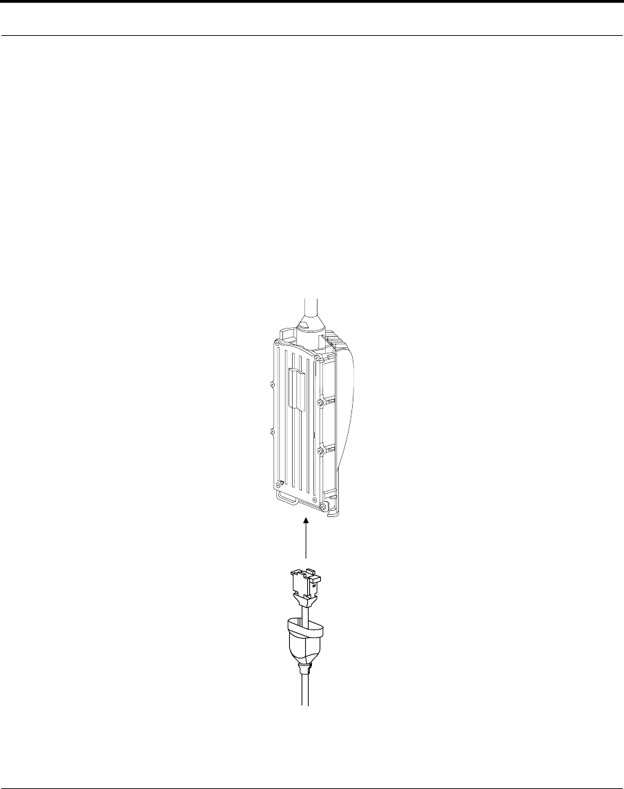
3. Plug the D-connector into the bottom of the wireless router. Guide the
connector very carefully onto the pins on the router. Using too much
force may damage the pins.
Before attaching the D-connector, make sure that the cover of the
wireless router is off. Attach the cover only after you have secured all
the connections on the router.
4. Tighten the two screws on the sides of the connector and slide the
rubber sleeve over the connections to keep them dry.
Be careful not to overtighten the screws as you can damage the router
case.
Attach multiwire connection
Nokia RoofTop™ Wireless Router Installation Guide 23
Installing the wireless router with an integral antenna
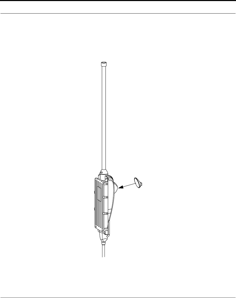
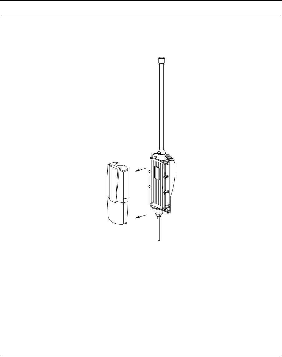
5. Attach the bolt and washer to the back of the router.
Do not tighten the bolt at this time as some flexibility is required to
attach the router to the mast mounting bracket.
Attach mounting bolt to router
Nokia RoofTop™ Wireless Router Installation Guide 24
Installing the wireless router with an integral antenna
6. Attach the front panel to the wireless router.
Attach front panel to wireless router
If you need to remove the wireless router cover after the D-connector is
already installed, pull it open by holding tightly onto the top of the cover.
Nokia RoofTop™ Wireless Router Installation Guide 25
Installing the wireless router with an integral antenna
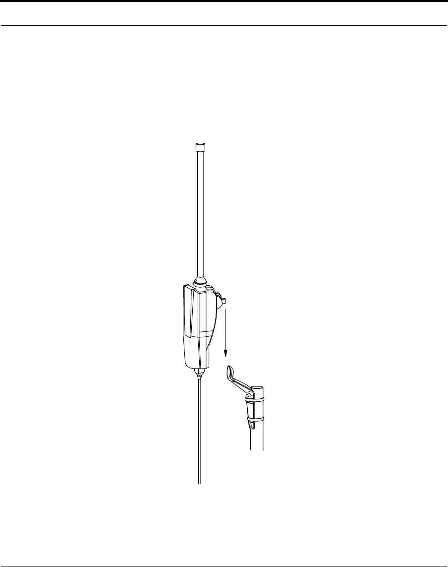
7. Attach the router to the mounting bracket.
Make sure the router is mounted vertical on the mount, using a level
as necessary, and tighten the bolt in the back of the router to torque of
9 ft./lb. (12 Nm). Be careful not to overtighten the bolt, you could
crack the plastic washer.
Slide the router mount onto the mast bracket
Nokia RoofTop™ Wireless Router Installation Guide 26
Installing the wireless router with an integral antenna
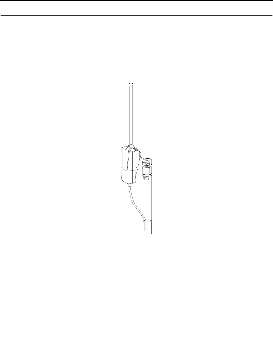
8. Using cable ties or adhesive tape, secure the multiwire cable to the
mast.
Take care to avoid placing strain on the connectors when securing the
cable to the mast. Use ties or tape about every two feet down the
length of the mast.
Secure the cable and ground wire
Nokia RoofTop™ Wireless Router Installation Guide 27
Installing the directional antenna
5.3 Installing the directional antenna
Assembling the directional antenna is slightly different from the integral
antenna. You use an RF cable between the antenna and the router. In
addition you need an RF cable adaptor which fits on top of the router and
connects the cable to the router. When you finish, the assembly looks like
this.
Installed router with directional antenna
To mount the antenna:
1. Attach the antenna to the mounting on the rooftop using the mounting
clamp. Tighten the nuts to fasten the antenna securely.
Nokia RoofTop™ Wireless Router Installation Guide 28
Installing the directional antenna
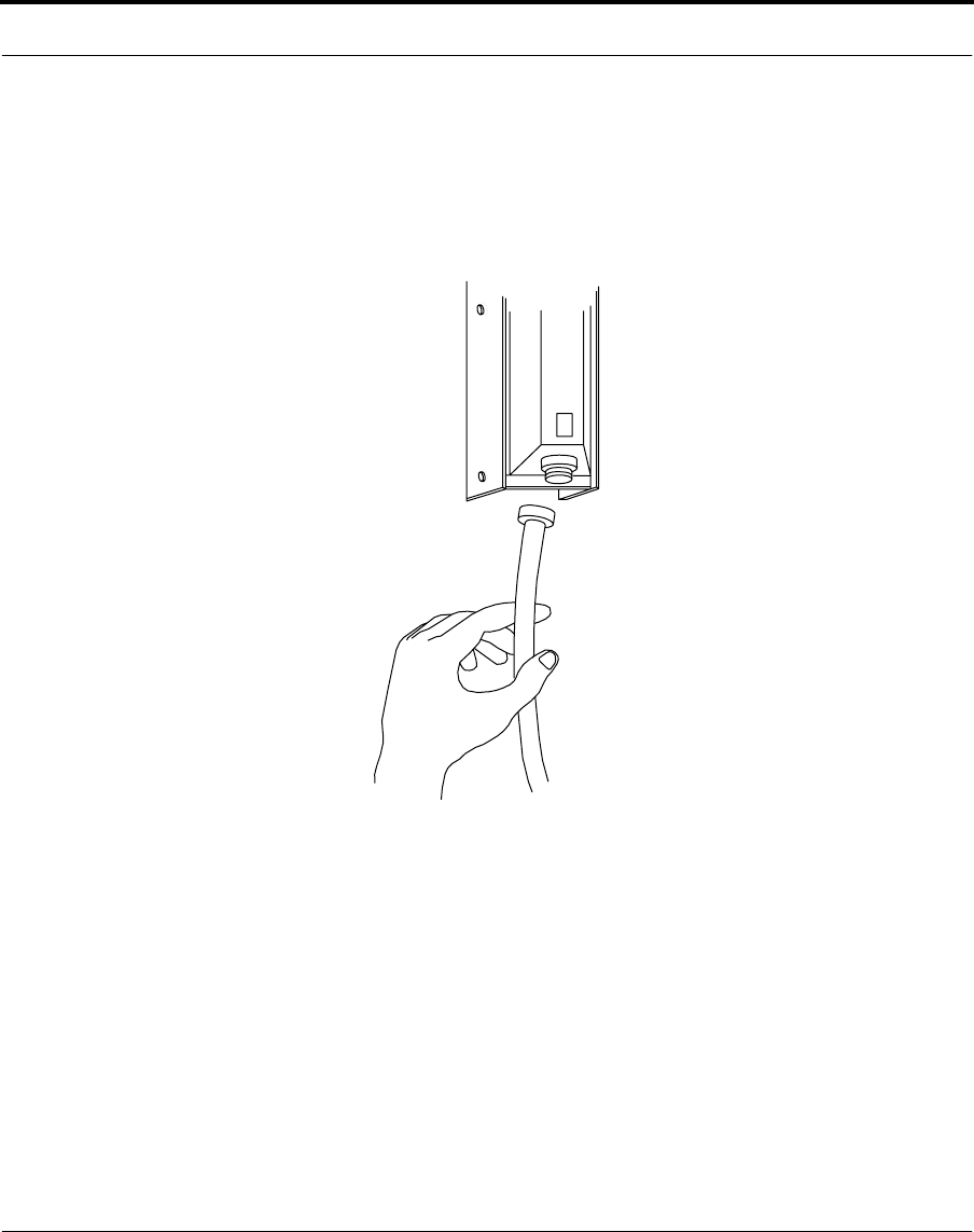
To assemble the antenna and router:
1. Connect an RF cable to the directional antenna ensuring that the
connections are properly tight, but do not overtighten.
Connect the wireless router to the directional antenna with the
jumper cable
2. Apply silicone lubricant on the threads of the RF cable adapter to
keep it from getting jammed. The recommended lubricant is: Dry
Lubricant PRF Tefsol.
•Spray a small amount of lubricant on the threads of the RF cable
adapter. Make sure not to spray any lubricant inside the
connector.
•Keep the RF cable adapter upside down for a few seconds until
the lubricant has dried up.
Nokia RoofTop™ Wireless Router Installation Guide 29
Installing the directional antenna
3. Attach the other end of the RF cable to the RF cable adaptor on the
top of the router.
This completes the connection between the antenna and the router.
Make sure the connections are tight but not overly so.
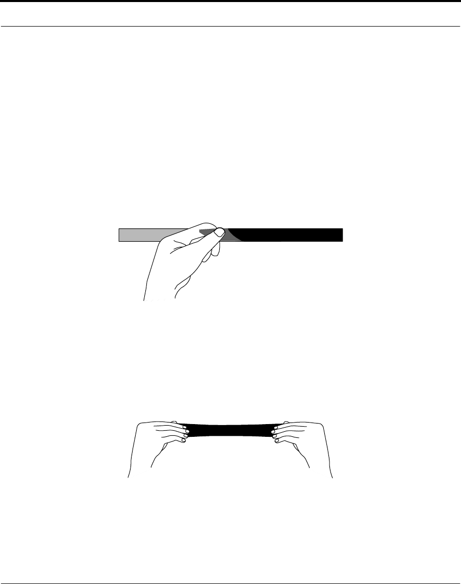
To weatherproof the antenna connection:
1. Cut an 8” strip of weatherproofing tape and remove the plastic
backing from the tape.
Remove plastic backing from the tape
2. Stretch the tape and apply the tape in the direction of the connector
thread to ensure that the connector does not come loose during the
weatherproofing process.
Stretching tape
Nokia RoofTop™ Wireless Router Installation Guide 30
Installing the directional antenna
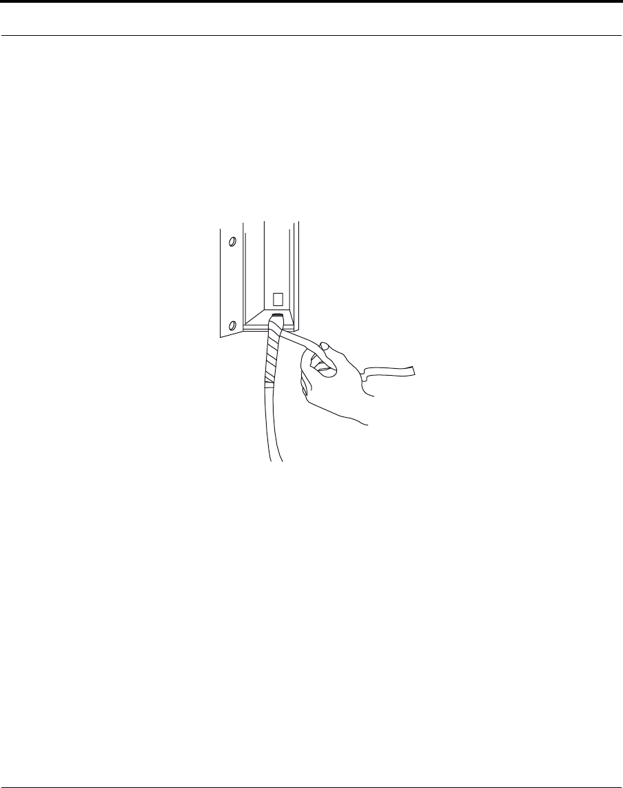
3. Apply the tape tightly in a counter clockwise direction starting at least
2 inches from the connector.
Move along the cable towards the connector so the tape covers the
bottom of the antenna and the top of the connector without gaps and
with a layer of overlapping.
Covering the directional antenna connection with weatherproof tape
Nokia RoofTop™ Wireless Router Installation Guide 31
Installing the directional antenna
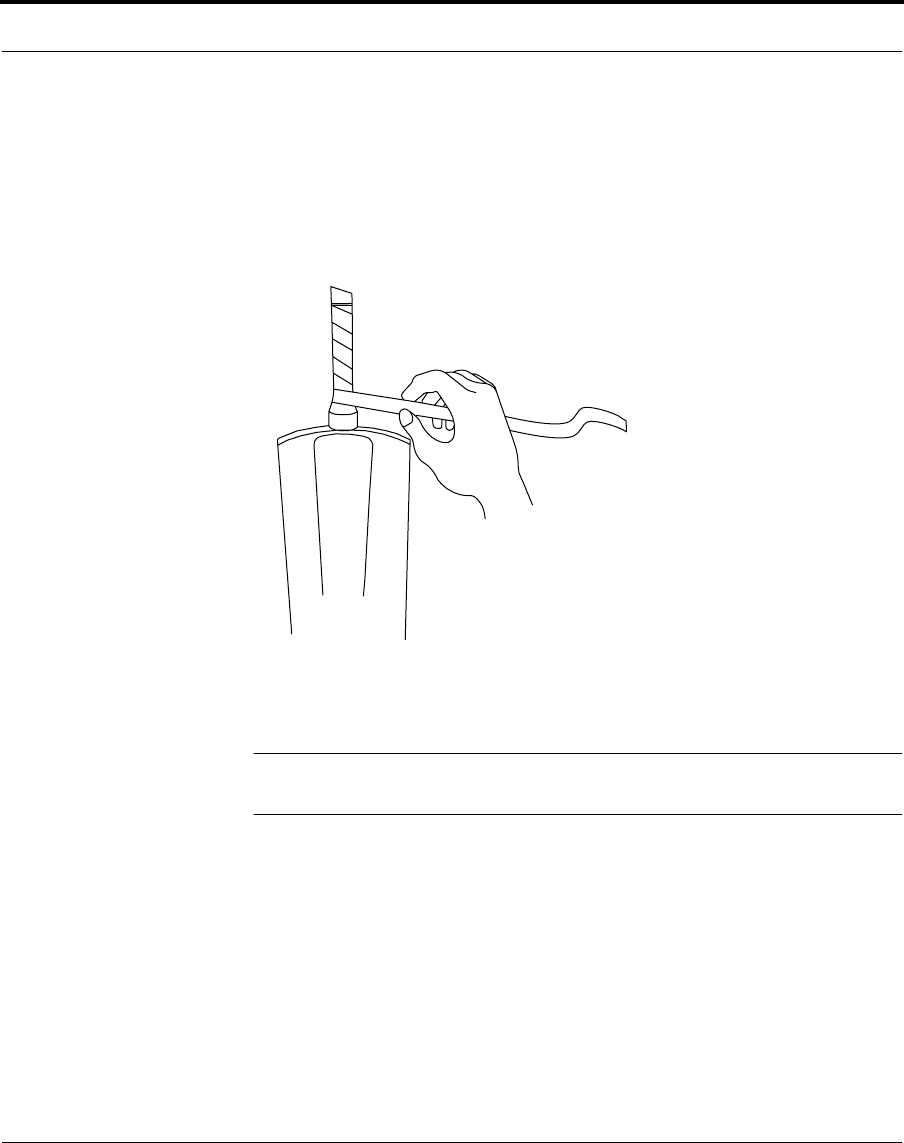
To weatherproof the router connection:
1. Apply tape tightly starting at least 2 inches from the connector.
Move along the cable toward the connector so that it covers the
connection completely.
Covering the Router connection with weatherproof tape
NOTE: Take care when weatherproofing RF connectors. Do not stress or
bend the cable during the weatherproofing process.
Nokia RoofTop™ Wireless Router Installation Guide 32
Installing the directional antenna
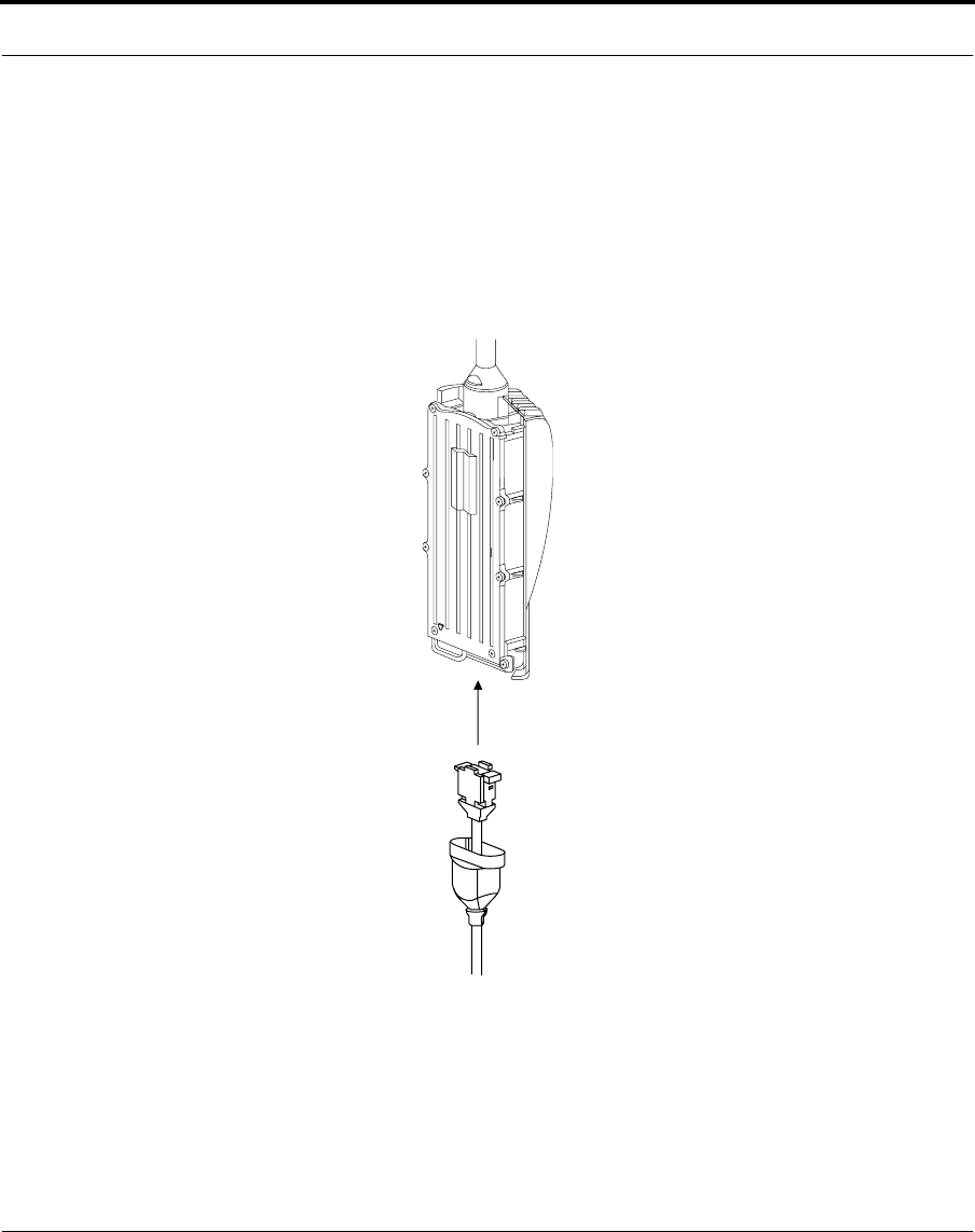
2. Plug the D-connector into the bottom of the wireless router. Guide the
connector very carefully onto the pins on the router. Using too much
force may damage the pins.
Before attaching the D-connector, make sure that the cover of the
wireless router is off. Attach the cover only after you have secured all
the connections on the router.
Attaching D-connector to router
3. Assemble the router with the front cover.
Refer to the instructions in the previous section, “Installing the wireless
router with an integral antenna” for mounting the router.
Nokia RoofTop™ Wireless Router Installation Guide 33
Grounding the router
5.4 Grounding the router
Because antennas are elevated metal objects with connections to ground,
they attract lightning.
The Nokia RoofTop Wireless Router has a grounding lug in it. A ground
wire can be attached to it to provide an appropriate and safe path to
ground for the lightning. Additional grounding is only required if the
existing grounding system within the property is insufficient for router
grounding purposes.
Section 810 of the National Electrical Code ANSINFPA No 70-1984
provides information about proper grounding of the mast and supporting
structure, grounding of the lead-in wire to an antenna discharge unit,
connection to grounding electrodes and requirements for the grounding
electrode.
To ground the router:
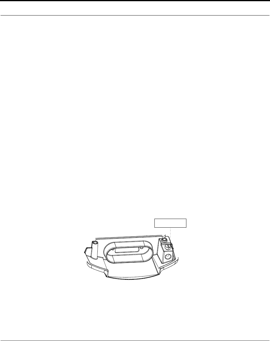
1. Connect a ground wire to the grounding lug at the bottom of the
router. The picture below shows the location of the grounding lug at
the bottom of the wireless router.
2. Run the ground wire from the router to the appropriate electrical
ground.
G r o u n d l u g
Nokia RoofTop™ Wireless Router Installation Guide 34
Grounding the router
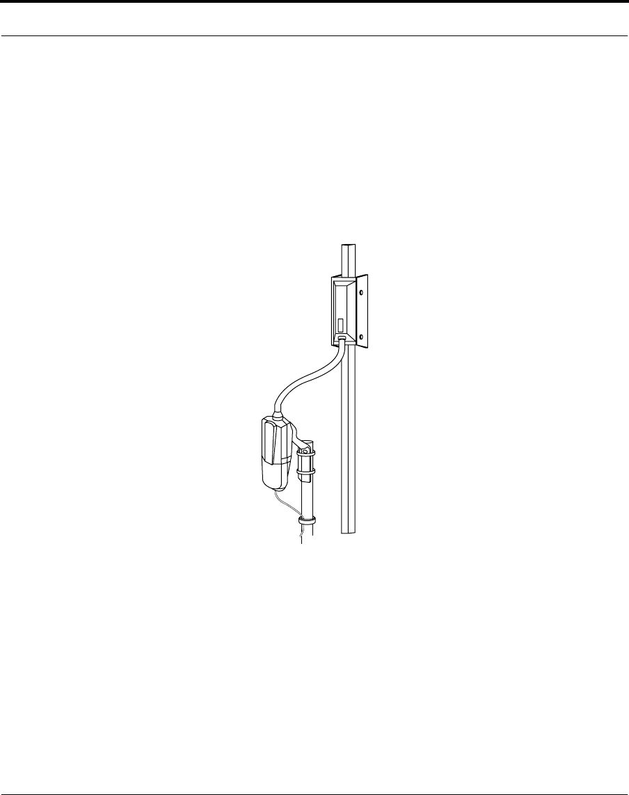
If a grounding kit is required:
Attach the grounding kit to the multiwire cable according to the
instructions that come with the kit before running the multiwire cable into
the house.
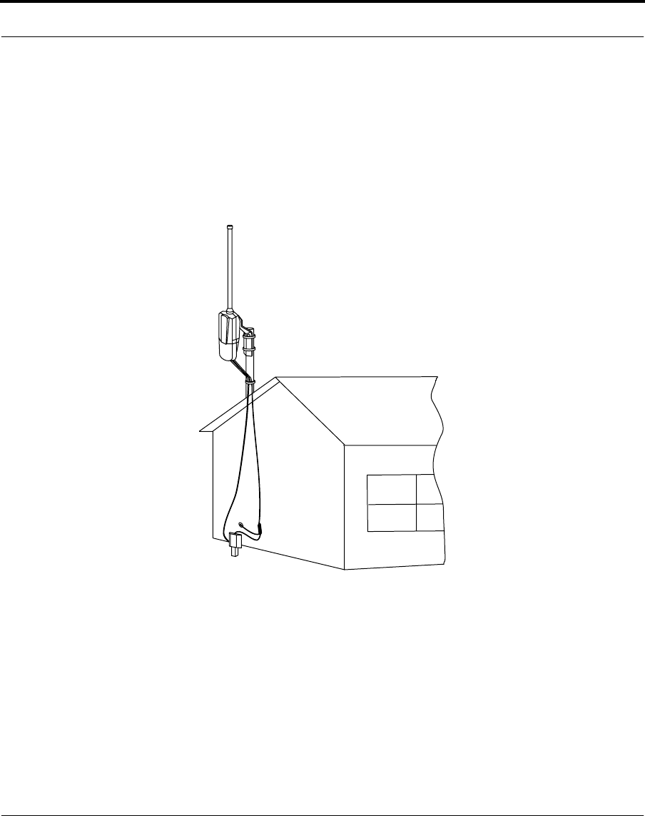
Illustration of complete installation (integral antenna)

Nokia RoofTop™ Wireless Router Installation Guide 34
CHAPTER 6 Installing the indoor components
6.1 Introduction
The second step in the wireless router installation is connecting the router
to the Network/Power Unit (NPU) and setting up the connection to the
computer.
35 Nokia RoofTop™ Wireless Router Installation Guide
6.1.1 The Network/ Power Unit (NPU)
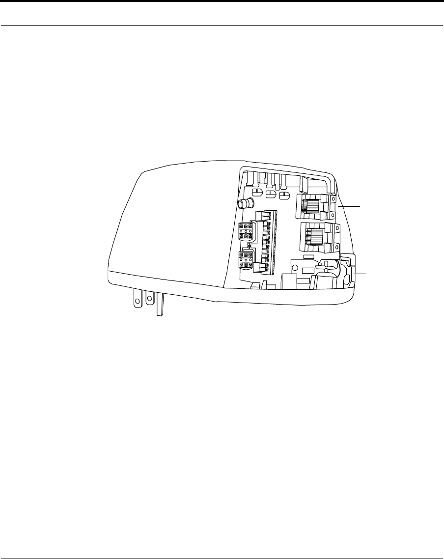
The NPU provides three cable connections.
•HomePNA 2.0 interface, a standard phone jack connection (RJ-11)
•Ethernet interface, a standard 10/100 BaseT Ethernet jack (RJ-45)
•Router outdoor unit connection, a multiwire cable connection
Three cable connections in the NPU
Ethernet (RJ 45)
Home PNA (RJ 11)
multiwire cable
Nokia RoofTop™ Wireless Router Installation Guide 36
Connecting the multiwire cable
6.2 Connecting the multiwire cable
To enable the NPU’s operation you must connect the multiwire cable
wires to pin connections inside the NPU.
To prepare the NPU:
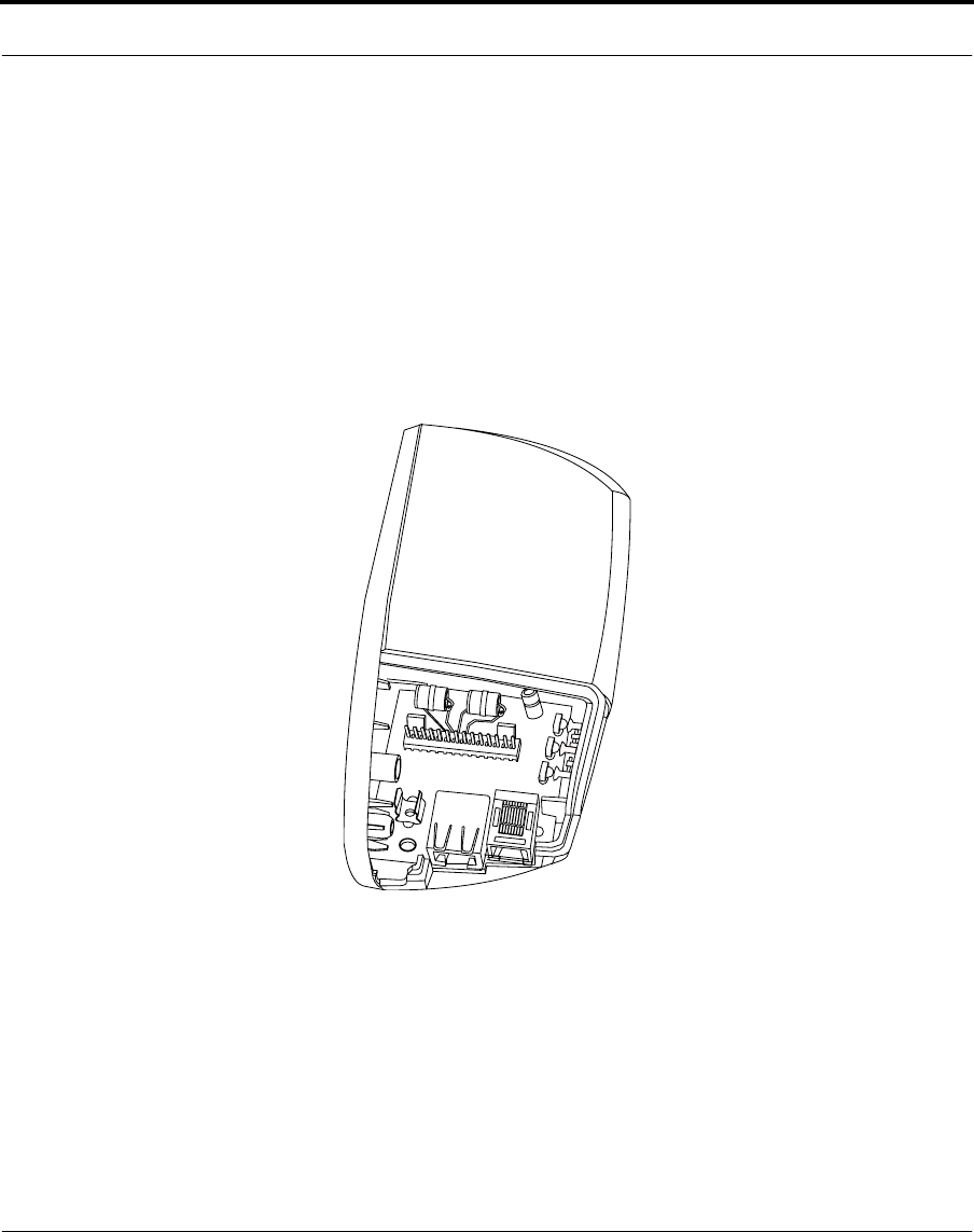
1. Remove the Network/Power Unit from its packaging.
Inside view of the NPU
2. Holding the multiwire cable, trim back the insulation about 2.5
inches. Make sure not to cut the metal braid and the foil. Slide the
insulation off (see picture below).
3. Cut the metal braid, foil and plastic coating about half an inch above
the insulation and carefully peel it off (see picture below).
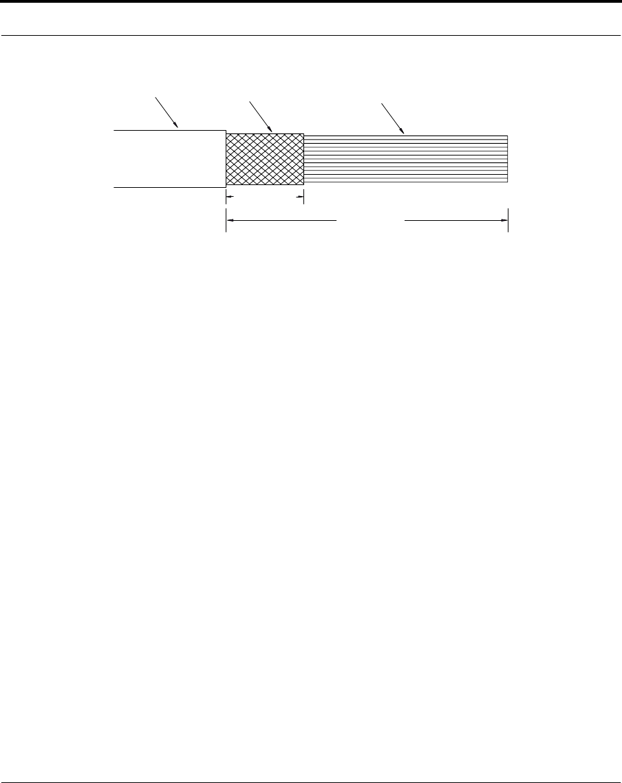
37 Nokia RoofTop™ Wireless Router Installation Guide
4. Separate the pairs of wires from one another keeping each pair
twisted together.
5. Separate the two wires in the brown and white pair and cut the brown
wire off. It is not used by the NPU.
6. Before starting to punch down the wires, hold the multiwire cable
over the NPU to measure at which point each wire should be punched
down. The metal braid should fit into the ground clip. You can trim
off excess wire after you have punched down all the wires.
I n s u l a t i o n M e t a l b r a i d W i r e s
0 . 5 i n c h
2 . 5 i n c h e s
Nokia RoofTop™ Wireless Router Installation Guide 38
Connecting the multiwire cable
To connect the wires and install the NPU:
NOTE: Do not push the pin connector down onto the pins inside the NPU
before all the wires have been punched down.
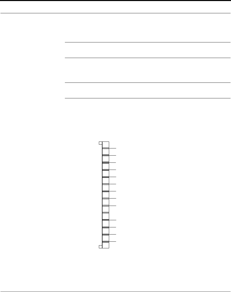
1. Connect the wires into the pin connector slots according to the
following chart.
NOTE: To punch down the wires, use the Molex punchdown tool (see Appendix
C for details). Standard punc-down tools are too small for the NPU.
The numbering in the below diagram only indicates the order of pins in
the NPU.
N o t e : T h e b r o w n w i r e i s n o t c o n n e c t e d a n d i s c u t o f
f
N P U W i r i n g
8
7
6
5
4
3
2
1
9
1 0
1 1
1 2
1 3
1 4
E T -
E R -
E R +
L D A
L D B
L D C
P N A +
P N A -
E T +
G N D
DC-
DC-
DC+
DC+
W h i t e / o r a n g e
O r a n g e
G r a y
W h i t e / g r a y
W h i t e / b r o w n
G r e e n
W h i t e / g r e e n
W h i t e / b l u e
B l u e
B l u e
R e d / b l u e
O r a n g e
R e d / o r a n g e
39 Nokia RoofTop™ Wireless Router Installation Guide
2. Keep the pairs twisted until the wires need to be separated for pin
connection.
This ensures a more consistent signal through the cable.
NOTE: It is especially important to keep the pairs with the blue wire
twisted together. Because there are two blue wires in the cable, you might
get them mixed up unless you keep them twisted with their pair up until
you punch them down into the connector.
3. Secure the wires tightly into the pin connector using either a punch
down tool or the integrated tool on the side of the NPU cover (see
picture below).
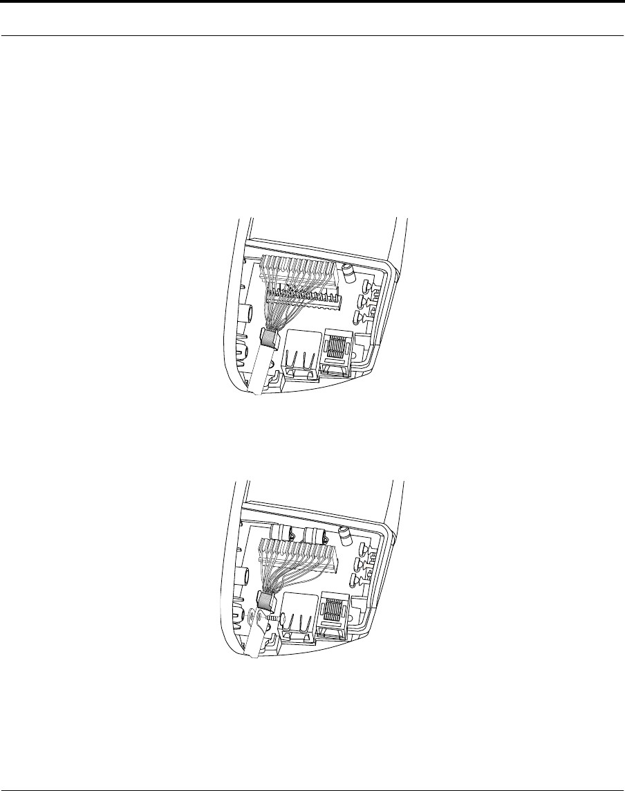
Nokia RoofTop™ Wireless Router Installation Guide 40
Connecting the multiwire cable
Using the NPU integrated punch down tool to connect the wires
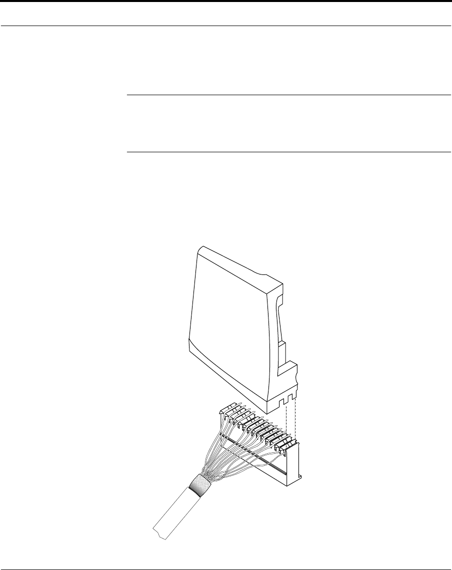
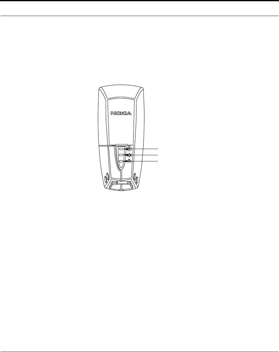
4. When all wires are connected securely, push the pin connector down
onto the pins inside the NPU (see picture below).
5. Place the part of the cable with the metal braid into the ground clip
(see picture below)
.
6. Connect the strain relief clamp in the NPU with the screw. This
prevents the multiwire cable from being pulled out.
7. Fit the NPU cover onto the NPU and attach it with the screw. Make
sure you use the correct size screwdriver (Pz1 or Ph1). Also press the
screwdriver hard enough to avoid damaging the screwhead. Do not
overtighten the screw.

41 Nokia RoofTop™ Wireless Router Installation Guide
8. Plug the NPU into the wall AC outlet. The LEDs on the unit should
flash three times to indicate that the NPU is connected to the router.
Nokia RoofTop™ Wireless Router Installation Guide 42
Identifying LED status
6.3 Identifying LED status
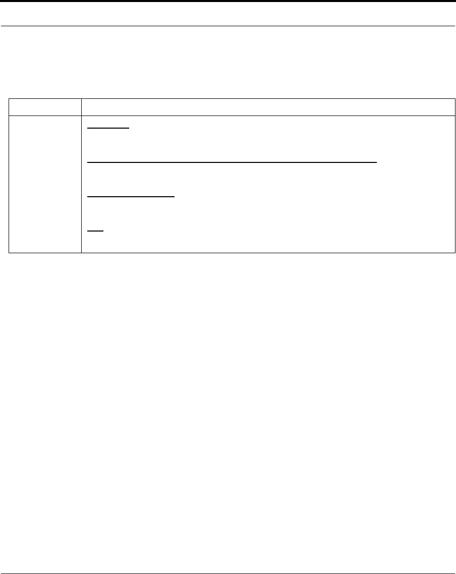
Each of the three LEDs on the face of the NPU serves a specific purpose
and can assume different states.
LEDs on face of Network/Power Unit
After the installation is finished, ideally the LEDs should indicate the
following:
•Anchor and network LED solid “ON”
You can also leave the LEDs in the following two states:
•Anchor and network LED “slow flashing” (the light flashes appr.
three times in five seconds) or
•Network LED “fast flashing” (the light flashes appr. six times in five
seconds). This state is not recommended and you should leave the
installation at this state only if absolutely necessary.
You should never leave the installation, if the Anchor LED is “fast
flashing”. If this is the case and you are not able to fix it, contact the
internet service provider.
P o w e r / L A
N
A n c h o r
N e t w o r k
43 Nokia RoofTop™ Wireless Router Installation Guide
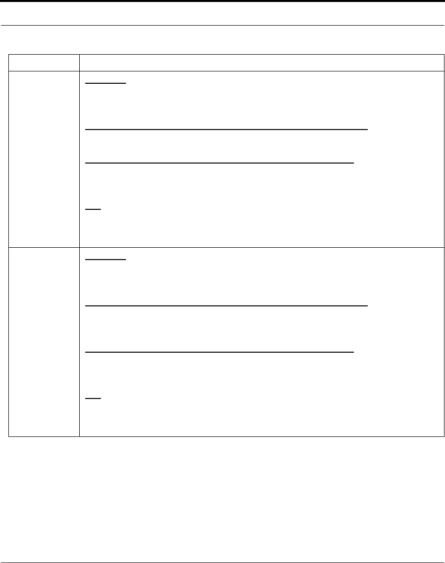
The following charts indicate the status of information flow for each LED
in each state.
LED Description
Power/ LAN Solid On
Power on
Slow Flash (the light flashes appr. three times in five seconds)
Waiting for the router to complete its startup cycle
Intermittent Flash
Flashes when transmitting or receiving wireless network packets
Off
Not receiving power, or the router is not functioning
Nokia RoofTop™ Wireless Router Installation Guide 44
Identifying LED status
Anchor Solid On
The data speed is 2Mb in at least one link and the AirHead is 3 or fewer hops
away from the router
Slow Flash (the light flashes appr. three times in five seconds)
The data speed is 1Mb and the AirHead is 3 or fewer hops away from the router
Fast Flash (the light flashes appr. six times in five seconds)
The unit is more than 3 hops away from the Airhead or there is no path to the Air
Head
Off
The Router has no neighbors and no connection to the AirHead
Network Solid On
There are at least 2 independent neighbors and at least one 2Mbps path to the Air-
Head. Also the path to the AirHead is 3 or fewer hops away
Slow Flash (the light flashes appr. three times in five seconds)
There are at least 2 independent neighbors and at least one 1Mbps path to the Air-
Head. Also the path to the AirHead is 3 or fewer hops away
Fast Flash (the light flashes appr. six times in five seconds)
There is at least 1 neighbor and a 2 Mbps path to the AirHead. Also the path to the
AirHead is 3 or fewer hops away
Off
None of the above
LED Description
45 Nokia RoofTop™ Wireless Router Installation Guide
6.4 Connecting to the computer
There are three ways to connect the wireless router to the computer
system.
•Direct Personal Computer Connection, using 10/100 Base-T
Ethernet crossover cable.
•Phoneline Networking Connection.
•Network Hub Connection, using 10/100 Base-T Ethernet
interface
The router automatically activates the Ethernet or HomePNA, depending
upon which connector is used. If a cable is connected to both connectors,
the Ethernet port is activated.
6.4.1 Direct personal computer connection
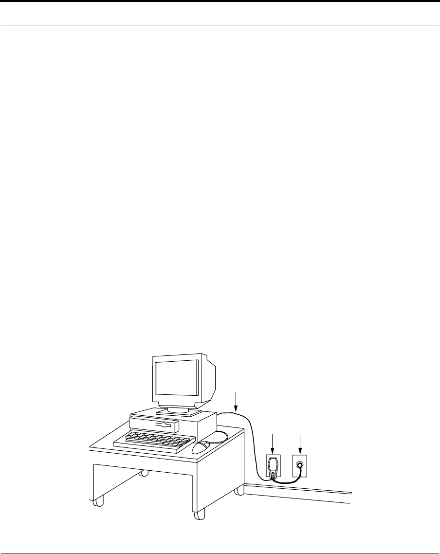
Connect an Ethernet crossover cable between the Network/Power Unit
and the personal computer Ethernet connection. Use an RJ-45 connector
at the NPU end, and the appropriate connector at the personal computer
end and connect the cables as shown below.
m u l t i w i r e
c a b l e
N P U
E t h e r n e t
Nokia RoofTop™ Wireless Router Installation Guide 46
Connecting to the computer
Attach NPU to computer through Ethernet cable
Use one crossover cable whenever a network hub is not being used.
NOTE: Changing the Ethernet configuration from a LAN connection to a
direct PC connection requires changing from a standard Ethernet cable to
a crossover cable.
6.4.2 Phoneline networking connection
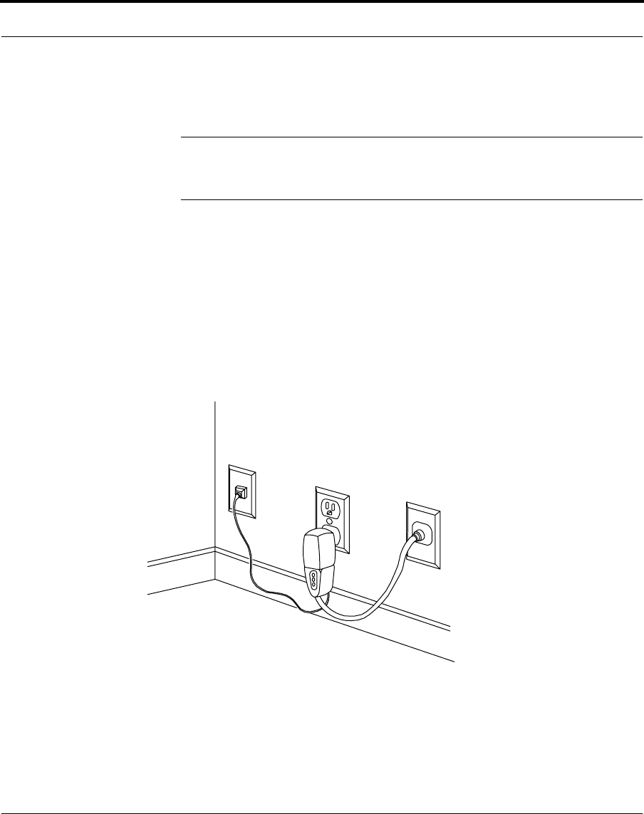
Connect a phone cable between the NPU’s phoneline networking
connection and the RJ-11 phone jack on the wall. You can make this
connection in any room, the most likely being near the place where the
multiwire cable enters the home.
Connect the NPU to the phone jack and multiwire cable
T o p h o n e l i n e
T o R o u t e
r

47 Nokia RoofTop™ Wireless Router Installation Guide
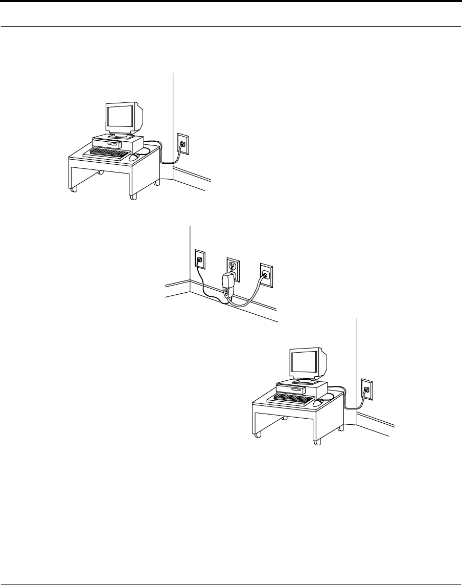
Once the NPU has been connected to a phone jack in the house, you can
connect PC's to the phoneline network through phoneline networking
adapters.
The phoneline networking adapters come in three varieties:
•USB adapter
•PCI card
•Ethernet/Phoneline networking gateway (if the computer already has
an Ethernet card)
PCI cards are used in desktop PC's and USB adapters can be used for
either desktop or portable PC's. Once these adapters have been installed in
or connected to a PC, the adapter must be connected to a RJ-11 phone
jack. Ensure that both the NPU and the phoneline networking adapters are
connected to the same phoneline in the house. Refer to the installation
manuals of phoneline networking adapters for more details.
Nokia RoofTop™ Wireless Router Installation Guide 48
Connecting to the computer
Attach multiple computers to phone jacks
R J 1 1 t o p h o n e l i n e
T o R o u t e r
49 Nokia RoofTop™ Wireless Router Installation Guide
6.4.3 Network connection
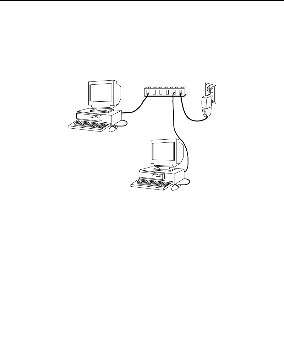
Use a standard Ethernet Cable with an RJ-45 connector at the wireless
router and the appropriate connector at the LAN Ethernet connection.
Attach computers and NPU to network hub

Nokia RoofTop™ Wireless Router Installation Guide 50
CHAPTER 7 Configuring the PC
7.1 Introduction
After the router installation is complete, the PC needs to be configured for
use with the Nokia Rooftop Wireless Router system. Anyone may do this
but it requires a good knowledge of the computer. The ISP provides all
the required information prior to installation.
This chapter gives brief instructions for configuring the PC with
Windows.

51 Nokia RoofTop™ Wireless Router Installation Guide
7.1.1 Configuring the personal computer
These instructions presume a knowledge of IP addresses.
1. Check that the PC has a network interface card (either HomePNA or
Ethernet).
If the PC does not have an interface card, install it.
2. Define the TCP/IP Properties.
In the IP Address field, either select the “Obtain IP Address
Automatically” or enter the IP Address and Subnet Mask in
accordance with information provided by the ISP.
3. In the Default Gateway field, enter the IP address of the default
gateway, provided by the ISP.

Nokia RoofTop™ Wireless Router Installation Guide 52
CHAPTER 8 Post installation testing
8.1 Introduction
After the router and NPU installation and PC configuration procedures
have been accomplished, you’ll want to test the system.
This chapter gives instructions for performing a few simple tests.

53 Nokia RoofTop™ Wireless Router Installation Guide
8.1.1 Testing
Ensure that the router functions correctly by carrying out the following
few steps.
To check out the system:
1. Ensure that the NPU is inserted properly into the AC outlet. The
LEDs flash three times to indicate that the router is functioning
correctly.
2. Turn on the PC. Wait for 3-5 minutes to allow the router to anchor to
the network.
3. Check the LEDs to indicate an active internet connection.
4. Open the web-browser and browse a few Internet pages to ensure that
the system downloads web sites.
NOTE: AOL customers will need to use dial-up connections for the AOL
browser to perform correctly. The router supports only Netscape and
Internet Explorer browsers.
5. Perform baseline testing according to the ISP’s instructions and note
the results. It is very important to know the download speeds of the
router.
6. Where there are problems with download or speed of connection,
check the installation first. If this does not solve the problem, then
contact the ISP.

Nokia RoofTop™ Wireless Router Installation Guide 54
APPENDIX A Cables
Ethernet crossover cable
The wiring for an Ethernet Crossover cable for 10Base-T is as follows:
RJ45 Plug
Pin 1 (Tx+) to Pin 3 (Rx+)
Pin 2 (Tx-) to Pin 6 (Rx-)
Pin 3 (Rx+) to Pin 1 (Tx+)
Pin 6 (Rx-) to Pin 2 (Tx-)

55 Nokia RoofTop™ Wireless Router Installation Guide

Nokia RoofTop™ Wireless Router Installation Guide 56
APPENDIX B Technical specifications
This appendix describes technical specifications for Nokia RoofTop™
Wireless Router Models R240 & 240A Outdoor-Mounted Unit.
Specifications
Data Capacity per Cell 12 Mbps
(6x2 Mbps per channel)
AirHeads per Cell
Routers per Cell
Routers per AirHead
Up to 6
Up to 240
Up to 40
Antenna Type (typical) 8 dBi Omnidirectional (integrated)
Maximum Link Range (typical)*
1 Mbps Data Rate
2 Mbps Data Rate
1.75 Miles
0.50 Miles
Radio/ Modem Specifications
Frequency Band (GHz)
Radio Type
Modulation
2.4000 - 2.4835
Frequency Hopping
Spread Spectrum
2 and 4 level GF SK

57 Nokia RoofTop™ Wireless Router Installation Guide
Transmit Power (typical)
Receiver Sensitivity(10-5 BER)
1Mbps Data Rate
2 Mbps Data Rate
12 dBm - 27.5 dBm (Dynamically adjusts in
1dB steps)
- 82 dBm (typical)
-72 dBm (typical)
Interfaces and Connectors
Ethernet
Phoneline Networking
RF
10/100 Base -TX, autosensing, RJ-45
Home PNA 2.0/ 1.0, RJ-11
N-Female (optional)
Router Environment
Operational Temperature
Relative Humidity
- 40o C to 55o C (-40o to 131o F)
100%
Weight
Router 3.3 lbs (including antenna and mount)
Dimensions
Router 4"W x 23/8"D x 81/4"H
NPU 13/4"W x 23/4"D x 51/2"H
Antenna (8dBi) 211/2"H x 3/4" Diameter
Power Consumption 16 Watts @ 120 VAC
Electrical Current Draw 100-120VAC 420mA, max AC current
21V / 1A, max DC current consumption during
normal operation
External Power Supply NA
Management Nokia Wireless Router Manager, SNMP MIB II,
Telnet
Maximum length of multiwire cable 150ft

Nokia RoofTop™ Wireless Router Installation Guide 58
* Refer to "Planning a Nokia RoofTop Wireless Network"
Internet Protocols IP, TCP, UDP, ICMP, RIPv1, RIPv2, SNMP,
TFTP, IGMP, ARP, Proxy-ARP, Telnet, DHCP
Relay, DHCP Server, NAT.
Agency Compliance FCC Class B, FCC CFR 47 Part 15, FCC Part 68
ICES-003, RSS-210, CS-03

59 Nokia RoofTop™ Wireless Router Installation Guide

Nokia RoofTop™ Wireless Router Installation Guide 62
APPENDIX C Tool requirements
Tools list
There follows a list of tools required for the correct installation of the
Nokia Wireless Router System.
Nokia shall not endorse, recommend or warrant the third party products
listed below or be under any liability whatsoever for any loss, damage,
injury or expense caused by them.
Tool Description Quantity required To be provided by
50 feet extension Cord - 15Amps 1 Installer
Flashlight 1 Installer
1/4" Socket set 14 piece 1 Installer
3/8" Socket set 14 piece 1 Installer
Metric combination wrench set 8mm to 19mm 1 Installer

63 Nokia RoofTop™ Wireless Router Installation Guide
Adjustable wrench 8" 1 Installer
Ratcheting screwdriver with bits (PFS 5400) 1 Installer
Screwdriver 5/16" x 6" 1 Installer
Screwdriver 1/4" x 1.5" 1 Installer
Screwdriver 1/4" x 4" 1 Installer
Screwdriver 3/16" x 4" 1 Installer
Screwdriver 3/8" x 8" 1 Installer
Screwdriver #1 CG 1 Installer
Screwdriver #2 CG 1 Installer
Screwdriver #3 CG 1 Installer
Diagonal cutters - large and small 1 Installer
Channel locks 10" 1 Installer
Cable cutter 8" 1 Installer
Utility Knife 1 Installer
Claw hammer 16oz (fiberglass) 1 Installer
Tape measure 26’ (english/ metric) 1 Installer
Utility pliers 10" 1 Installer
Safety glasses - clear 1 Installer
Leather work gloves 1 Installer
Tool box 1 Installer
Multimeter 1 Installer
Heat gun 1 Installer
Wrist strap ESD 1 Installer
Rubber mallet 2lbs 1 Installer
Power screwdriver and bit set 1 Installer
Power drills - corded and cordless 1 Installer
Drill bit set 1 Installer
Cable snake 1 Installer
Molex punchdown tool, ordering number 11-
02-0016 for connector type 7720
1 Installer
Tool Description Quantity required To be provided by

Nokia RoofTop™ Wireless Router Installation Guide 64
RJ-45 Connector crimp tool 1 Installer
Cordless hand vacuum 1 Installer
Keyhole saw 1 Installer
Stud finder 1 Installer
Small wire strippers 1 Installer
Large wire strippers 1 Installer
Scissors 1 Installer
Small needlenose pliers 1 Installer
Tool Description Quantity required To be provided by

65 Nokia RoofTop™ Wireless Router Installation Guide

Nokia RoofTop™ Wireless Router Installation Guide 66
APPENDIX D D-connector specifications
Nokia provides different lenghts of multiwire cable with the D-connector
installed. Should you need to connect the multiwire cable to the D-
connector for testing or other purposes, the diagram below tells you how
to connect the wires.When connecting the wires, keep the pairs twisted
until the wires need to be separated for pin connection.This ensures a
more consistent signal through the cable.
E T +
D 1
b l u e
D 1 5 - c o n n e c t o r
S i g n a l n a m e s
D 2
D 3
D 4
D 5
D 6
D 7
D 8
D 9
D 1 0
D 1 1
D 1 2
D 1 3
D 1 4
D 1 5
w h i t e / b l u e
o r a n g e
w h i t e / o r a n g e
w h i t e / b r o w n
n o t c o n n e c t e d
o r a n g e
r e d / o r a n g e
green
w h i t e / g r e e n
g r e y
w h i t e / g r e y
n o t c o n n e c t e d
b l u e
r e d / b l u e
E T -
E R +
E R -
L D A
D C +
D C +
P N A +
P N A -
L D C
L D B
D C -
D C -

67 Nokia RoofTop™ Wireless Router Installation Guide
