Nokia Solutions and Networks FZCWI2A1 Wireless Access Point User Manual 10 23
Nokia Solutions and Networks, OY Wireless Access Point 10 23
Contents
- 1. User Manual Regulatory Information_10.23.pdf
- 2. User Manual_10.23.pdf
- 3. User Manual - Regulatory Information_11.15.pdf
User Manual_10.23.pdf
Package Contents
• Access point
• Bracket
• Logo sticker
• Quick Installation Guide
Tools Required
• Marker
• Measuring tape
• Screws
• Screw driver
• Hammer
• Network cables
• POE power or DC power adapter
1. Before unpacking the carton, ensure that the packaging is intact, not damaged or soaked.
2. Unpack the carton and check if all the items listed in the package contents are included.
3. Tools are not supplied with the WI2A-AC200i box.
NOTE
This Quick Installation Guide Nokia Wi-Fi Access Point WI2A-AC200i provides basic
information and step-by-step installation instructions. Following these steps will
enable you to properly install the WI2A-AC200i at your site.
Thank you for buying a Nokia Wi-Fi Access Point WI2A-AC200i.
Nokia Wi-Fi Access Point WI2A-AC200i
Pre-requisites
• Please read all the notes and safety statements in this guide before beginning the installation process.
• The WI2A-AC200i is designed for an indoor environment (e.g. temperature range of 0°C to 40°C, non-condensing).
• Allow 10 cm of space around the access point to ensure proper cooling.
• Install the WI2A-AC200i away from heat sources, water/wet surfaces, and strong magnetic field sources or electrical appliances
(ex: microwave ovens).
• Using an incorrect power adapter may permanently damage the product.
•
Legal Notices
The information contained herein is subject to change without notice. The only warranties for Nokia products and services are set
forth in the express warranty statements accompanying such products and services. Nothing herein should be construed as
constituting an additional warranty. Nokia Solutions and Networks shall not be liable for technical or editorial errors or omissions
contained herein.
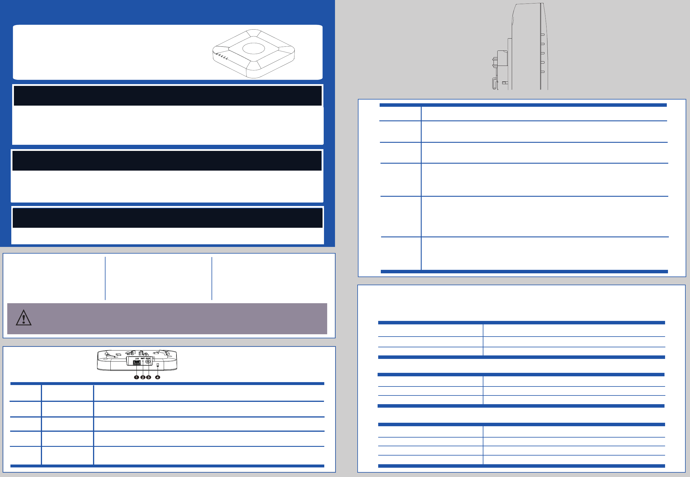
12 3 4
Product Overview
Off - LAN Connection Not Detected
Red - LAN Connection Detected
Red blinking - AP IP address Discovery process
Green - AP IP address obtained (DHCP or Static but not factory default)
Green blinking - LAN Activity after IP address has been obtained
2.4 GHz
ETH
5 GHz
Off - LAN Connection Not Detected or AP IP Address not available
Red - AP IP address available but Controller IP is being discovered or Invalid Controller IP
Red blinking - Controller IP Available and Connection in Progress
Green -Connected to Controller and in steady state
Green blinking - Connected to Controller and Configuration in Progress
Amber blinking - Connected to Controller and Software Download in Progress
PWR
CTRL
ETH
2.4G
5G
LAN PORT
Reset button
Power port
Security Lock Slot4
Used to reboot or restore WI2A-AC200i. Press and release the button to reboot WI2A-AC200i.
Press and hold the button for 10 seconds to restore factory settings.
Port for Ethernet cable to connect the WI2A-AC200i to LAN and POE (if available).
Description
Name
Number
3
2
1
Specification Summary
Weight
Nokia WI2A-
AC200i physical specification
Nokia WI2A-AC200i electrical specification
Nokia WI2A-AC200i environmental specification
The following table describes the physical, electrical and environmental specifications.
Item Description
Dimensions
150mm x 150mm x 30mm (without bracket)
400g
Item Description
Power input
+12V/1A
≤12W
Power consumption
Item Description
Working temperature 0°C ~ +40°C
5% to 95% non-condensing
Operating humidity
IP20
Dustproof and Waterproof
• Regulatory Information
Port to connect a DC power supply unit if POE is unavailable.
Slot for security lock and cable for theft protection.
PWR
CTRL
Off - No SSID Configured on 2.4 GHz
Green - 2.4 GHz SSID Configured and Broadcasting
Red – AP is locked by Controller
Off - No SSID Configured on 5 GHz
Green - 5 GHz SSID Configured and Broadcasting
Red – AP is locked by Controller
LED
Color – Indication
Off - No Power to AP
Red - Board Power On
Red blinking - Loading Software
Green - Software Loaded
Red blinking for more than 5 minutes - Failure to load Software properly (if LED control is working)
Accessories Needed
Label material and adhesive have been designed to last the lifetime of the product when installed in accordance with Nokia
installation guidelines.
© Nokia Solutions and Networks 2015.
Label Statements
Hardware Operation
NOTE
Ensure that Nokia WI2A-AC200i is securely installed. Poor installation may cause the device to fall and be damaged.
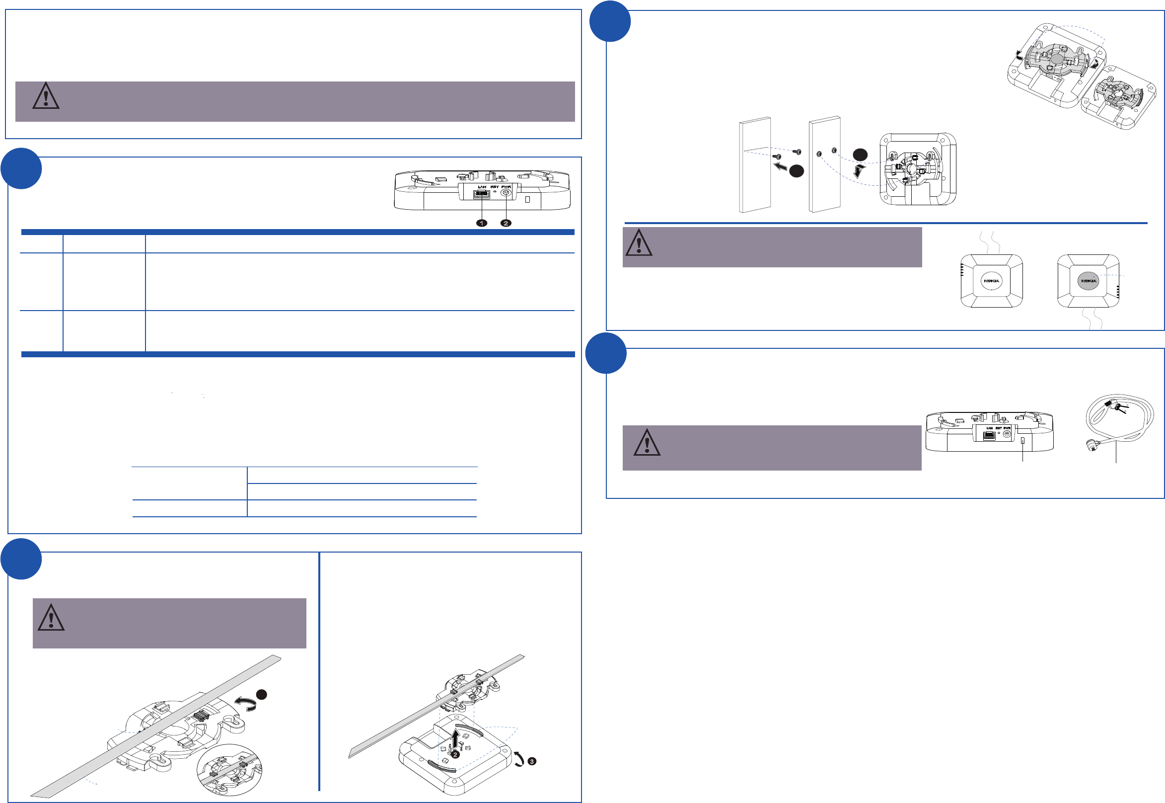
There is a security lock slot with an anti-theft design provided on the WI2A-AC200i.
1. Fasten the security lock cable to an immovable object.
2. Insert the security lock cable into the security lock slot of the WI2A-AC200i and then lock it.
Installing the security lock
The box does not include a security lock cable. It needs
to be purchased separately.
3
Voltage range: 37V~ 57V
PD: 12.95W, support
Category-5
Enhanced
100m cable
12 V DC nominal, +/- 5%
PoE
DC Power Adapter
Item Name Description
1
2
1
The following figure illustrates the interface and cable connections of the WI2A-AC200i:
Connecting cables
• Category-5 Enhanced Ethernet cable is recommended.
• Ensure that the WI2A-AC200i is connected to the LAN using a correct Ethernet cable.
• The WI2A-AC200i might fail to power up or work if non-standard Ethernet cable is used.
Ethernet cable
DC Power adapter
•
A DC power adapter is required only if a PoE power supply is not available.
1. Align the securing hook of WI2A-AC200i with the bracket.
2. To firmly fasten the WI2A-AC200i to the bracket, rotate the
bracket in the clockwise direction
(as shown in the figure on the right) until it completely locks into the WI2A-AC200i.
3. Drive two screws in the wall with a distance of 79mm between them.
4. Align the bracket hole with the screws, and then pull the bracket down over the screws until it is
tightly fastened.
Recommended wall mounting for the WI2A-AC200i is with the cables run upward.
If the cables are run downward, the Nokia Logo sticker can be placed on the
WI2A-AC200i to display an upright Nokia logo.
Cabling options are shown in the figure to the right.
Scenario 2: Wall mounting
12
The WI2A-AC200i requires either PoE or DC power supply to operate.
To use the PoE power supply:
Connect the WI2A-AC200i to the PoE power supply (such as PoE injector or PoE switch) using an Ethernet cable.
To use the DC power supply:
Connect the WI2A-AC200i to the DC power supply.
Use only PoE and DC power supplies that meet these specifications:
Securing
Hook
3
2
T-rail
Bracket Clips1
Bracket Clips2
Scenario 1: Ceiling mounting
1. Choose a pair of bracket clips to firmly mount the bracket with
the T-rails.
2. Align the securing hook of the WI2A-AC200i with the
secured bracket.
3. To firmly fasten the WI2A-AC200i with the bracket, rotate
the WI2A-AC200i in
the anti-clockwise
direction.
1
The bracket provides two pairs of clips. Select the correct
pair based on the T-rail width. The following figure
illustrates the bracket clips.
NOTE
2
Securing Hook
7
9
m
m
3
4
Upward
Downward
Logo sticker
Security lock slot Security lock cable
NOTE
2
NOTE
Placing of Nokia Logo sticker while wall mounting
The Nokia® WI2A-AC200i can be ceiling or wall mounted. Ceiling mounting is recommended.
Please read the safety instructions before working with the product.
•
To connect the WI2A-AC200i to a DC power source and prevent damage, use the power adapter specified
for the WI2A-AC200i.