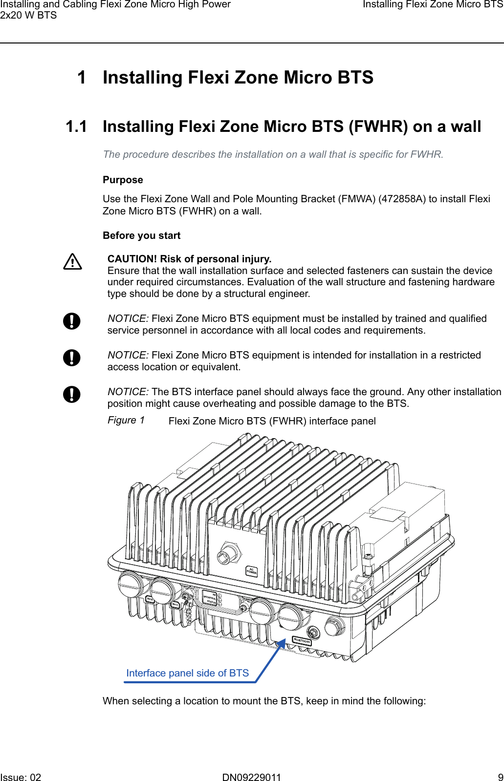
Nokia Solutions and Networks FZMFWHR01 Flexi Zone Micro BTS User Manual

Nokia Solutions and Networks, OY Flexi Zone Micro BTS

User Manual

Installing and Cabling FlexiZone Micro High Power 2x20W BTS DN09229011Issue 02Approval Date yyyy-mm-dd NokiaNetworks
The information in this document applies solely to the hardware/software product (“Product”) specifiedherein,andonlyasspecifiedherein.ThisdocumentisintendedforusebyNokiaSolutionsandNetworks'customers(“You”)only,anditmaynotbeusedexceptforthepurposesdefinedintheagreementbetweenYouandNokiaSolutionsandNetworks(“Agreement”) under which this document is distributed. No part of this document may be used, copied,reproduced, modified or transmitted in any form or means without the prior written permission of NokiaSolutions and Networks. If you have not entered into an Agreement applicable to the Product, or if thatAgreementhasexpiredorhasbeenterminated,YoumaynotusethisdocumentinanymannerandYouareobligedtoreturnittoNokiaSolutionsandNetworksanddestroyordeleteanycopiesthereof.The document has been prepared to be used by professional and properly trained personnel, and Youassumefullresponsibilitywhenusingit.NokiaSolutionsandNetworkswelcomeYourcommentsaspartoftheprocessofcontinuousdevelopmentandimprovementofthedocumentation.This document and its contents are provided as a convenience to You. Any information or statementsconcerningthesuitability,capacity,fitness forpurposeorperformanceoftheProduct are givensolelyonan“asis”and“asavailable”basisinthisdocument,andNokiaSolutionsandNetworksreservestherighttochangeanysuchinformationandstatementswithoutnotice.NokiaSolutionsandNetworkshasmadeallreasonableeffortstoensurethatthecontentofthisdocumentisadequateandfreeofmaterialerrorsandomissions, and Nokia Solutions and Networks will correct errors that You identify in this document. But,NokiaSolutionsandNetworks'totalliabilityforanyerrorsinthedocumentisstrictlylimitedtothecorrectionofsucherror(s).NokiaSolutionsandNetworksdoesnotwarrantthattheuseofthesoftwareintheProductwillbeuninterruptedorerror-free.NOWARRANTYOFANY KIND,EITHER EXPRESS ORIMPLIED, INCLUDINGBUT NOTLIMITEDTOANY WARRANTY OF AVAILABILITY, ACCURACY, RELIABILITY, TITLE, NON-INFRINGEMENT,MERCHANTABILITY OR FITNESS FOR A PARTICULAR PURPOSE, IS MADE IN RELATION TO THECONTENT OF THIS DOCUMENT. IN NO EVENT WILL NOKIA SOLUTIONS AND NETWORKS BELIABLE FOR ANY DAMAGES, INCLUDING BUT NOT LIMITED TO SPECIAL, DIRECT, INDIRECT,INCIDENTAL OR CONSEQUENTIAL OR ANY LOSSES, SUCH AS BUT NOT LIMITED TO LOSS OFPROFIT, REVENUE, BUSINESS INTERRUPTION, BUSINESS OPPORTUNITY OR DATA THAT MAYARISEFROMTHEUSEOFTHISDOCUMENTORTHEINFORMATIONINIT,EVENINTHECASEOFERRORSINOROMISSIONSFROMTHISDOCUMENTORITSCONTENT.ThisdocumentisNokiaSolutionsandNetworks’proprietaryandconfidentialinformation,whichmaynotbedistributed or disclosed to any third parties without the prior written consent of Nokia Solutions andNetworks.Nokiais a registered trademarkof Nokia Corporation. Otherproduct names mentioned inthis documentmaybetrademarksoftheirrespectiveowners,andtheyarementionedforidentificationpurposesonly.Copyright©2016NokiaSolutionsandNetworks.Allrightsreserved.fImportant Notice on Product SafetyThisproductmaypresentsafetyrisksduetolaser,electricity,heat,andothersourcesofdanger.Only trained and qualified personnel may install, operate, maintain or otherwise handle thisproductandonlyafterhavingcarefullyreadthesafetyinformationapplicabletothisproduct.The safety information is provided in the Safety Information section in the “Legal, Safety andEnvironmentalInformation”partofthisdocumentordocumentationset.Nokia Solutions and Networks is continually striving to reduce the adverse environmental effects of itsproductsandservices.Wewouldliketoencourageyouasourcustomersanduserstojoinusinworkingtowardsacleaner,saferenvironment.Pleaserecycleproductpackagingandfollowtherecommendationsforpoweruseandproperdisposalofourproductsandtheircomponents.IfyoushouldhavequestionsregardingourEnvironmentalPolicyoranyoftheenvironmentalservicesweoffer,pleasecontactusatNokiaSolutionsandNetworksforanyadditionalinformation.InstallingandCablingFlexiZoneMicroHighPower2x20WBTS2 DN09229011 Issue:02
Table of ContentsThisdocumenthas67pages Summaryofchanges..................................................................... 8 1 InstallingFlexiZoneMicroBTS..................................................... 91.1 InstallingFlexiZoneMicroBTS(FWHR)onawall........................ 91.2 InstallingFlexiZoneMicroBTS(FWHR)onaverticalpole......... 171.3 InstallingFlexiZoneMicroBTS(FWHR)onahorizontalpole.....24 2 CablingFlexiZoneMicroBTS..................................................... 322.1 Cablingthecopperinterface........................................................ 342.2 Cablingtheopticalinterface.........................................................372.3 FlexiZoneMicroBTS(FWHR)interfaces....................................41 3 Installingantennas....................................................................... 433.1 Installingomnidirectionalantennas.............................................. 433.2 Installingthird-partyantennas...................................................... 433.3 ConsiderationsforremotelyconnectingRFantennas................. 443.4 InstallingBluetoothantenna.........................................................453.4.1 Bluetoothantenna........................................................................ 453.5 InstallingGPSantenna................................................................ 463.5.1 GPSantenna(FAWD).................................................................. 46 4 RequirementsforGPSantennainstallation................................. 484.1 Introduction.................................................................................. 484.1.1 Scope........................................................................................... 484.1.2 TheGlobalPositioningSystem.................................................... 484.1.2.1 Satelliteconstellation................................................................... 484.1.2.2 GPSRFcarrier.............................................................................494.2 Generalantennapositioningrequirements.................................. 494.2.1 Requiredantennavisibility........................................................... 504.2.2 Antennaplacementoptimization.................................................. 504.2.3 Lightningprotection......................................................................514.2.4 Antennablockage........................................................................ 514.2.5 RFinterference............................................................................ 514.3 IntegratedGPSantennaoperation.............................................. 524.4 Remotelypositionedantennaoperation.......................................534.4.1 ActiveGPSantenna.....................................................................544.4.1.1 Antennaelement.......................................................................... 544.4.1.2 Low-noiseamplifier(LNA)/Pre-selectorfilter..............................544.4.1.3 OverallGPSantennaRFrequirements....................................... 544.4.2 RFcabling.................................................................................... 554.4.3 Lightningarrestor......................................................................... 554.4.4 GPSantennasystemRFrequirements....................................... 564.4.4.1 Antennasystemgain....................................................................56InstallingandCablingFlexiZoneMicroHighPower2x20WBTSIssue:02 DN09229011 3
4.4.4.2 Antennasystemnoisefigure........................................................574.4.4.3 GPSmountingbrackets............................................................... 58 5 ContentsofFlexiZoneMicroBTSdelivery..................................59 6 FlexiZoneMicroBTSinstallationtoolsandequipment............... 60 7 SafetyforPublicandWorkers......................................................617.1 Installingbasestationstoensurepublicsafety............................617.2 Installingbasestationstoensureinstallersafety.........................61 8 FlexiZoneMicroBTS(FWHR)UnitedStatesFCCPart15compliance................................................................................... 63 9 FlexiZoneMicroBTS(FWHR)IndustryCanadaICRSS-GENcompliance................................................................................... 64 10 FlexiZoneMicroBluetoothModularApproval............................. 66 11 EURoHSstatement.....................................................................67InstallingandCablingFlexiZoneMicroHighPower2x20WBTS4 DN09229011 Issue:02
List of FiguresFigure1 FlexiZoneMicroBTS(FWHR)interfacepanel.................................... 9Figure2 FlexiZoneMicroBTSclearances.......................................................11Figure3 Disassemblingthemountingbracket..................................................12Figure4 Fixingtheinterfacebracket................................................................ 12Figure5 Staticmountingbracketkeyholes.......................................................13Figure6 Drillingtheholes................................................................................. 13Figure7 Installingthestaticmountingbracketonthewall............................... 14Figure8 Rubberpluglocation...........................................................................15Figure9 Correctbracketalignment.................................................................. 16Figure10 InstallingtheBTSonawall................................................................ 16Figure11 FlexiZoneMicroBTS(FWHR)interfacepanel.................................. 17Figure12 FlexiZoneMicroBTSclearances.......................................................19Figure13 Disassemblingthemountingbracket..................................................20Figure14 Fixingtheinterfacebracket................................................................ 20Figure15 Threadingthestrainingstraps............................................................ 21Figure16 Installingtheinstallationplatetothepole...........................................21Figure17 Rubberpluglocation...........................................................................22Figure18 Correctbracketalignment.................................................................. 23Figure19 InstallingtheBTSonaverticalpole................................................... 23Figure20 FlexiZoneMicroBTS(FWHR)interfacepanel.................................. 24Figure21 FlexiZoneMicroBTSclearances.......................................................26Figure22 Disassemblingthemountingbracket..................................................27Figure23 Fixingtheinterfacebracket................................................................ 28Figure24 Threadingthestrainingstraps............................................................ 28Figure25 Installingthestaticmountingbracketonthepole...............................29Figure26 Rubberpluglocation...........................................................................30Figure27 Correctbracketalignment.................................................................. 31Figure28 InstallingtheBTSonahorizontalpole............................................... 31Figure29 Powercablealignment....................................................................... 33Figure30 CompletecablingoftheFlexiZoneMicroBTS.................................. 34Figure31 Removingtheseal..............................................................................35Figure32 Preparingthecoppercable................................................................ 35Figure33 Connectingthecoppercable..............................................................36Figure34 FasteningthegrommettotheBTS.....................................................36Figure35 Pushingthegrommetintothegrommethousing................................37Figure36 Fasteningthenuttothegrommethousing......................................... 37Figure37 Removingtheseal..............................................................................38Figure38 Preparingtheopticalcable................................................................. 38InstallingandCablingFlexiZoneMicroHighPower2x20WBTSIssue:02 DN09229011 5
Figure39 Connectingtheopticalcable.............................................................. 39Figure40 Fasteningthefiberextendertube.......................................................39Figure41 Fasteningthegrommethousingintothefiberextendertube............. 40Figure42 Pushingthegrommetintothegrommethousing................................40Figure43 Fasteningthenuttothegrommethousing......................................... 41Figure44 FlexiZoneMicroBTS(FWHR)interfaces-bottomview....................42Figure45 FlexiZoneMicroBTS(FWHR)interfaces-topview..........................42Figure46 Bluetoothantenna.............................................................................. 46Figure47 FAWD................................................................................................. 47Figure48 FAWDlabel.........................................................................................47Figure49 CellsiteGPSsatellitevisibility............................................................49Figure50 MaximizingGPSantennavisibility......................................................50Figure51 GPSantennaplacementconsiderations............................................ 51Figure52 MaximumGPSreceiverinterferencepowerlevelvs.frequency........ 52Figure53 TypicalRFGPSantennaconfigurationdiagram................................ 53Figure54 RemoteRFGPSantennaconfigurationdiagram............................... 54Figure55 GPSantennalossbudget/noisefigurecalculation........................... 58InstallingandCablingFlexiZoneMicroHighPower2x20WBTS6 DN09229011 Issue:02
List of TablesTable1 Releasescoveredbythedocument..................................................... 8Table2 FlexiZoneMicroBTS(FWHR)maintenanceclearances...................10Table3 FlexiZoneMicroBTS(FWHR)maintenanceclearances...................18Table4 FlexiZoneMicroBTS(FWHR)maintenanceclearances...................25Table5 FlexiZoneMicroBTS(FWHR)interfaces.......................................... 41Table6 PropertiesoftheBluetoothantenna................................................... 45Table7 PropertiesofGPSantenna(FAWD)(472932A)................................. 46Table8 RecommendedGPSantennaspecifications...................................... 54Table9 Antennacablelossandbendradiusdata.......................................... 55Table10 FlexiZoneMicroBTSdeliverycontents............................................. 59Table11 FMWAFlexiZoneWallandPoleMountingBracket(472858A)deliverycontents.............................................................................................. 59Table12 Installationtools..................................................................................60Table13 RequiredComplianceBoundaries(CB)byband...............................61InstallingandCablingFlexiZoneMicroHighPower2x20WBTSIssue:02 DN09229011 7
Summary of changesChangesbetweendocumentissuesarecumulative.Therefore,thelatestdocumentissuecontainsallchangesmadetopreviousissues.ThisdocumentiscommonforallTDD-LTEreleases.YoumayfindhereinformationaboutsolutionsthatarenotavailableorsupportedinaspecificSWreleaseorRAT.ForfeaturessupportedinyourSWrelease,seerespectivefeaturedocumentationchapterinthesystemlibrary.Table1 ReleasescoveredbythedocumentProduct ReleaseTDLTE TD-LTE15A,TD-LTE16ThisdocumentcontainsinstructionsthatarespecificforFlexiZoneMicroBTS(FWHR).Changes between issues 01 (2015-12-22) and 02 (yyyy-mm-dd)Thefollowingsectionshavebeenadded:•Installingbasestationstoensureinstallersafety•FlexiZoneMicroBTS(FWHR)UnitedStatesFCCPart15compliance•FlexiZoneMicroBTS(FWHR)IndustryCanadaICRSS-GENcompliance•FlexiZoneMicroBluetoothModularApproval•EURoHSstatementIssue 01Thisisthefirstissueofthedocument.Summaryofchanges InstallingandCablingFlexiZoneMicroHighPower2x20WBTS8 DN09229011 Issue:02 
1  Installing Flexi Zone Micro BTS1.1  Installing Flexi Zone Micro BTS (FWHR) on a wallTheproceduredescribestheinstallationonawallthatisspecificforFWHR.PurposeUsetheFlexiZoneWallandPoleMountingBracket(FMWA)(472858A)toinstallFlexiZoneMicroBTS(FWHR)onawall.Before you startfCAUTION! Risk of personal injury.Ensurethatthewallinstallationsurfaceandselectedfastenerscansustainthedeviceunderrequiredcircumstances.Evaluationofthewallstructureandfasteninghardwaretypeshouldbedonebyastructuralengineer.wNOTICE:FlexiZoneMicroBTSequipmentmustbeinstalledbytrainedandqualifiedservicepersonnelinaccordancewithalllocalcodesandrequirements.wNOTICE:FlexiZoneMicroBTSequipmentisintendedforinstallationinarestrictedaccesslocationorequivalent.wNOTICE:TheBTSinterfacepanelshouldalwaysfacetheground.AnyotherinstallationpositionmightcauseoverheatingandpossibledamagetotheBTS.Figure1 FlexiZoneMicroBTS(FWHR)interfacepanelRFBACKHAULSTATUSBHCBHBACPOWERBLUETOOTHInterfacepanelsideofBTSWhenselectingalocationtomounttheBTS,keepinmindthefollowing:InstallingandCablingFlexiZoneMicroHighPower2x20WBTSInstallingFlexiZoneMicroBTSIssue:02 DN09229011 9 
•AvoidmountingtheBTSsuchthattheantennasareblockedbyotherstructuressuchaswalls.Adirectlineofsighttotheareatobecoveredwillprovidethebestperformance.•Keepothermetallicmountingfeaturesasfarawayfromallantennasaspossible.•KeepcablesroutedandsecuredawayfromtheLTEandBluetoothantennas.•RemotelylocatingtheBluetoothantennaisnotallowed.•Sinceonlyremotelyconnectedantennasaresupported,externallightningsurgeprotectionmustbeadded.Formoreinformationonremotelymountingantennas,seesectionInstallingantennas.Ifsideclearanceislessthanscrewdriverlength,thegroundingcableneedstobepre-installed.TheminimumandrecommendedmaintenanceclearancesareshowninTable2:FlexiZoneMicroBTS(FWHR)maintenanceclearances.Table2 FlexiZoneMicroBTS(FWHR)maintenanceclearancesBTS side Minimum clearances Recommended clearancesFront 50mm(1.97in) 500mm(19.68in)Rear 35mm(1.38in)(1) 35mm(1.38in)(1)Top 100mm(3.94in) Heightoftheunit+10mm(0.39in)Bottom 100mm(3.94in) 300mm(11.81in)Left 10mm(0.39in)(2) 10mm(0.39in)(2)Right 10mm(0.39in) 10/110mm(0.39/4.33in)(3)(1)Forwallandpoleinstallations.(2)Forhorizontalpoleinstallationstheclearancemustbeatleast20mm(0.78in).(3)Dependsonthescrewdriverlength.InstallingFlexiZoneMicroBTS InstallingandCablingFlexiZoneMicroHighPower2x20WBTS10 DN09229011 Issue:02 
Figure2 FlexiZoneMicroBTSclearancesRightFrontRearBottomTopLeftProcedure1 Disassemble the mounting bracket.Themountingbracketconsistsoftwoelements:theinterfacebracketandstaticbracket.Loosenthetwothumbscrews(M6),slideuptheinterfacebracketandputasidethestaticbracket.Notethatthumbscrews(M6)areintegralpartsoftheinterfacebracket.InstallingandCablingFlexiZoneMicroHighPower2x20WBTSInstallingFlexiZoneMicroBTSIssue:02 DN09229011 11 
Figure3 DisassemblingthemountingbracketInterfacebracketStaticbracket2 Fix the interface bracket to the Flexi Zone Micro BTS using two M6 cap screwsand washers included with the mounting bracket.Tightenthescrewsto5.1Nm(3.8ft-lb).Figure4 FixingtheinterfacebracketInstallingFlexiZoneMicroBTS InstallingandCablingFlexiZoneMicroHighPower2x20WBTS12 DN09229011 Issue:02 
3 Mark the mounting screw locations on the wall and drill the holes for thescrews.tTip:  Usethestaticmountingbracketkeyholesasatemplate.Figure5 StaticmountingbracketkeyholesKeyholesfordrilltemplateFigure6 Drillingtheholes115(4.53in.)mm4 Fix the mounting bolts to the wall, and install the static mounting bracket onthe wall.ThestaticmountingbracketkeyholesaredesignedtosuitM6screws.Checkthatthebracketislevel.InstallingandCablingFlexiZoneMicroHighPower2x20WBTSInstallingFlexiZoneMicroBTSIssue:02 DN09229011 13 
Figure7 InstallingthestaticmountingbracketonthewallInstallingFlexiZoneMicroBTS InstallingandCablingFlexiZoneMicroHighPower2x20WBTS14 DN09229011 Issue:02 
5 Tighten the bracket’s fastener according to the manufacturer’s instructions.6 Install the BTS to the static mounting bracket.wNOTICE:Ifyoulifttheunitwitharope,useanM6sizeeyeboltwithaM6x1.0thread.TheeyeboltshouldbefixedtothetopoftheBTS,inplaceoftherubberplug.TheeyeboltshouldberemovedandreplacedwiththerubberplugafterinstallingtheBTS.Theeyeboltisnotpartofthedeliveryandmustbeorderedseparately.Figure8 RubberpluglocationRubberpluga) PositiontheBTSwiththeinterfacebracketaligneddirectlyabovethestaticmountingbracket.b) SlidedowntheBTSuntilitisfullylocatedandseatedontothestaticbracket.c) Handstartthethumbscrews(M6)tosecureBTStostaticbracket.d) TorqueallM6screwsto5.1Nm(3.8ft-lb).InstallingandCablingFlexiZoneMicroHighPower2x20WBTSInstallingFlexiZoneMicroBTSIssue:02 DN09229011 15 
gNote:  Beforetighteningthescrewsmakesurethat:•thestaticmountingbracketissecurelycaptivatedintheinterfacebracket'sslot.•tabsontheinterfacebracketarecaptivatedbythebacksurfaceofthestaticmountingbracket.Figure9 CorrectbracketalignmentTabsoninterfacebracketTabonstaticbracketSlotininterfacebracketFigure10 InstallingtheBTSonawallInstallingFlexiZoneMicroBTS InstallingandCablingFlexiZoneMicroHighPower2x20WBTS16 DN09229011 Issue:02 
1.2  Installing Flexi Zone Micro BTS (FWHR) on avertical poleTheproceduredescribestheinstallationonaverticalpolethatisspecificforFWHR.PurposeUsetheFlexiZoneWallandPoleMountingBracket(FMWA)(472858A)andbandstrapstoinstallFlexiZoneMicroBTSonapole.Thebandstrapsdependonthechosenpolediameter.Thewidthofthebandstrapsshouldbelessthan¾"toproperlyfitintotheslotsofthemountingbracket.Before you startfCAUTION! Risk of personal injury.Ensurethattheselectedbandstrapscansustainthedeviceunderrequiredcircumstances.TheselectedbandstrapsshouldberatedforoutdooruseandbecapableofsecuringtheBTSweight.Acertifiedstructuralengineershouldinspectandapprovethemountingpoleandhardwarepriortoinstallation.wNOTICE:FlexiZoneMicroBTSequipmentmustbeinstalledbytrainedandqualifiedservicepersonnelinaccordancewithalllocalcodesandrequirements.wNOTICE:FlexiZoneMicroBTSequipmentisintendedforinstallationinarestrictedaccesslocationorequivalent.wNOTICE:TheBTSinterfacepanelshouldalwaysfacetheground.AnyotherinstallationpositionmightcauseoverheatingandpossibledamagetotheBTS.Figure11 FlexiZoneMicroBTS(FWHR)interfacepanelRFBACKHAULSTATUSBHCBHBACPOWERBLUETOOTHInterfacepanelsideofBTSInstallingandCablingFlexiZoneMicroHighPower2x20WBTSInstallingFlexiZoneMicroBTSIssue:02 DN09229011 17 
gNote:  Thebandstrapsarenotpartofthedeliveryandmustbeorderedseparately.WhenselectingalocationtomounttheBTS,keepinmindthefollowing:•AvoidmountingtheBTSsuchthattheantennasareblockedbyotherstructuressuchaswalls.Adirectlineofsighttotheareatobecoveredwillprovidethebestperformance.•Keepothermetallicmountingfeaturesasfarawayfromallantennasaspossible.•KeepcablesroutedandsecuredawayfromtheLTEandBluetoothantennas.•RemotelylocatingtheBluetoothantennaisnotallowed.•Sinceonlyremotelyconnectedantennasaresupported,externallightningsurgeprotectionmustbeadded.Formoreinformationonremotelymountingantennas,seesectionInstallingantennas.Ifsideclearanceislessthanscrewdriverlength,thegroundingcableneedstobepre-installed.TheminimumandrecommendedmaintenanceclearancesareshowninTable2:FlexiZoneMicroBTS(FWHR)maintenanceclearances.Table3 FlexiZoneMicroBTS(FWHR)maintenanceclearancesBTS side Minimum clearances Recommended clearancesFront 50mm(1.97in) 500mm(19.68in)Rear 35mm(1.38in)(1) 35mm(1.38in)(1)Top 100mm(3.94in) Heightoftheunit+10mm(0.39in)Bottom 100mm(3.94in) 300mm(11.81in)Left 10mm(0.39in)(2) 10mm(0.39in)(2)Right 10mm(0.39in) 10/110mm(0.39/4.33in)(3)(1)Forwallandpoleinstallations.(2)Forhorizontalpoleinstallationstheclearancemustbeatleast20mm(0.78in).(3)Dependsonthescrewdriverlength.InstallingFlexiZoneMicroBTS InstallingandCablingFlexiZoneMicroHighPower2x20WBTS18 DN09229011 Issue:02 
Figure12 FlexiZoneMicroBTSclearancesRightFrontRearBottomTopLeftProcedure1 Disassemble the mounting bracket.Themountingbracketconsistsoftwoelements:theinterfacebracketandstaticbracket.Loosenthetwothumbscrews(M6),slideuptheinterfacebracketandputasidethestaticbracket.Notethatthumbscrews(M6)areintegralpartsoftheinterfacebracket.InstallingandCablingFlexiZoneMicroHighPower2x20WBTSInstallingFlexiZoneMicroBTSIssue:02 DN09229011 19 
Figure13 DisassemblingthemountingbracketInterfacebracketStaticbracket2 Fix the interface bracket to the Flexi Zone Micro BTS using two M6 cap screwsand washers included with the mounting bracket.Tightenthescrewsto5.1Nm(3.8ft-lb).Figure14 FixingtheinterfacebracketInstallingFlexiZoneMicroBTS InstallingandCablingFlexiZoneMicroHighPower2x20WBTS20 DN09229011 Issue:02 
3 Thread the straining straps to the static mounting bracket.Figure15 Threadingthestrainingstraps4 Install the static mounting bracket to the pole with the straining straps.gNote:  Thestrapsshouldbetightenedandsecuredaccordingtothestrapmanufacturer’sinstructionsandthebracketshouldbesecureandimmovable.Figure16 InstallingtheinstallationplatetothepoleInstallingandCablingFlexiZoneMicroHighPower2x20WBTSInstallingFlexiZoneMicroBTSIssue:02 DN09229011 21 
5 Tighten the straining straps around the pole.6 Install the BTS to the static mounting bracket.wNOTICE:Ifyoulifttheunitwitharope,useanM6sizeeyeboltwithaM6x1.0thread.TheeyeboltshouldbefixedtothetopoftheBTS,inplaceoftherubberplug.TheeyeboltshouldberemovedandreplacedwiththerubberplugafterinstallingtheBTS.Theeyeboltisnotpartofthedeliveryandmustbeorderedseparately.Figure17 RubberpluglocationRubberpluga) PositiontheBTSwiththeinterfacebracketaligneddirectlyabovethestaticmountingbracket.b) SlidedowntheBTSuntilitisfullylocatedandseatedontothestaticbracket.c) Handstartthethumbscrews(M6)tosecuretheBTStothestaticbracket.d) TorqueallM6screwsto5.1Nm(3.8ft-lb).InstallingFlexiZoneMicroBTS InstallingandCablingFlexiZoneMicroHighPower2x20WBTS22 DN09229011 Issue:02 
gNote:  Beforetighteningthescrewsmakesurethat:•thestaticmountingbracketissecurelycaptivatedintheslotintheinterfacebracket.•tabsontheinterfacebracketarecaptivatedbythebacksurfaceofthestaticmountingbracket.Figure18 CorrectbracketalignmentTabsoninterfacebracketTabonstaticbracketSlotininterfacebracketFigure19 InstallingtheBTSonaverticalpoleInstallingandCablingFlexiZoneMicroHighPower2x20WBTSInstallingFlexiZoneMicroBTSIssue:02 DN09229011 23 
1.3  Installing Flexi Zone Micro BTS (FWHR) on ahorizontal poleTheproceduredescribestheinstallationonahorizontalpolethatisspecificforFWHR.PurposeUsetheFlexiZoneWallandPoleMountingBracket(FMWA)(472858A)andbandstrapstoinstallFlexiZoneMicroBTSonapole.Thebandstrapsdependonthechosenpolediameter.Thewidthofthebandstrapsshouldbelessthan¾"toproperlyfitintotheslotsofthemountingbracket.Before you startfCAUTION! Risk of personal injury.Ensurethattheselectedbandstrapscansustainthedeviceunderrequiredcircumstances.TheselectedbandstrapsshouldberatedforoutdooruseandbecapableofsecuringtheBTSweight.Acertifiedstructuralengineershouldinspectandapprovethemountingpoleandhardwarepriortoinstallation.wNOTICE:FlexiZoneMicroBTSequipmentmustbeinstalledbytrainedandqualifiedservicepersonnelinaccordancewithalllocalcodesandrequirements.wNOTICE:FlexiZoneMicroBTSequipmentisintendedforinstallationinarestrictedaccesslocationorequivalent.wNOTICE:TheBTSinterfacepanelshouldalwaysfacetheground.AnyotherinstallationpositionmightcauseoverheatingandpossibledamagetotheBTS.Figure20 FlexiZoneMicroBTS(FWHR)interfacepanelRFBACKHAULSTATUSBHCBHBACPOWERBLUETOOTHInterfacepanelsideofBTSInstallingFlexiZoneMicroBTS InstallingandCablingFlexiZoneMicroHighPower2x20WBTS24 DN09229011 Issue:02 
gNote:  Thebandstrapsarenotpartofthedeliveryandmustbeorderedseparately.WhenselectingalocationtomounttheBTS,keepinmindthefollowing:•AvoidmountingtheBTSsuchthattheantennasareblockedbyotherstructuressuchaswalls.Adirectlineofsighttotheareatobecoveredwillprovidethebestperformance.•Keepothermetallicmountingfeaturesasfarawayfromallantennasaspossible.•KeepcablesroutedandsecuredawayfromtheLTEandBluetoothantennas.•RemotelylocatingtheBluetoothantennaisnotallowed.•Sinceonlyremotelyconnectedantennasaresupported,externallightningsurgeprotectionmustbeadded.Formoreinformationonremotelymountingantennas,seesectionInstallingantennas.Ifsideclearanceislessthanscrewdriverlength,thegroundingcableneedstobepre-installed.TheminimumandrecommendedmaintenanceclearancesareshowninTable2:FlexiZoneMicroBTS(FWHR)maintenanceclearances.Table4 FlexiZoneMicroBTS(FWHR)maintenanceclearancesBTS side Minimum clearances Recommended clearancesFront 50mm(1.97in) 500mm(19.68in)Rear 35mm(1.38in)(1) 35mm(1.38in)(1)Top 100mm(3.94in) Heightoftheunit+10mm(0.39in)Bottom 100mm(3.94in) 300mm(11.81in)Left 10mm(0.39in)(2) 10mm(0.39in)(2)Right 10mm(0.39in) 10/110mm(0.39/4.33in)(3)(1)Forwallandpoleinstallations.(2)Forhorizontalpoleinstallationstheclearancemustbeatleast20mm(0.78in).(3)Dependsonthescrewdriverlength.InstallingandCablingFlexiZoneMicroHighPower2x20WBTSInstallingFlexiZoneMicroBTSIssue:02 DN09229011 25 
Figure21 FlexiZoneMicroBTSclearancesRightFrontRearBottomTopLeftProcedure1 Disassemble the mounting bracket.Themountingbracketconsistsoftwoelements:theinterfacebracketandstaticbracket.Loosenthetwothumbscrews(M6),slideuptheinterfacebracketandputasidethestaticbracket.Notethatthumbscrews(M6)areintegralpartsoftheinterfacebracket.InstallingFlexiZoneMicroBTS InstallingandCablingFlexiZoneMicroHighPower2x20WBTS26 DN09229011 Issue:02 
Figure22 DisassemblingthemountingbracketInterfacebracketStaticbracket2 Fix the interface bracket to the Flexi Zone Micro BTS using two M6 cap screwsand washers included with the mounting bracket.Tightenthescrewsto5.1Nm(3.8ft-lb).InstallingandCablingFlexiZoneMicroHighPower2x20WBTSInstallingFlexiZoneMicroBTSIssue:02 DN09229011 27 
Figure23 Fixingtheinterfacebracket3 Thread the straining straps to the static mounting bracket.Figure24 ThreadingthestrainingstrapsInstallingFlexiZoneMicroBTS InstallingandCablingFlexiZoneMicroHighPower2x20WBTS28 DN09229011 Issue:02 
4 Install the static mounting bracket on the pole with the straining straps.gNote:  Thestrapsshouldbetightenedandsecuredaccordingtothestrapmanufacturer’sinstructionsandthebracketshouldbesecureandimmovable.Figure25 InstallingthestaticmountingbracketonthepoleInstallingandCablingFlexiZoneMicroHighPower2x20WBTSInstallingFlexiZoneMicroBTSIssue:02 DN09229011 29 

Navigation menu