Nokia Solutions and Networks FZMFWHR01 Flexi Zone Micro BTS User Manual
Nokia Solutions and Networks, OY Flexi Zone Micro BTS
User Manual

Installing and Cabling Flexi
Zone Micro High Power 2x20
W BTS
DN09229011
Issue 02
Approval Date yyyy-mm-dd
NokiaNetworks

The information in this document applies solely to the hardware/software product (“Product”) specified
herein,andonlyasspecifiedherein.
ThisdocumentisintendedforusebyNokiaSolutionsandNetworks'customers(“You”)only,anditmaynot
beusedexceptforthepurposesdefinedintheagreementbetweenYouandNokiaSolutionsandNetworks
(“Agreement”) under which this document is distributed. No part of this document may be used, copied,
reproduced, modified or transmitted in any form or means without the prior written permission of Nokia
Solutions and Networks. If you have not entered into an Agreement applicable to the Product, or if that
Agreementhasexpiredorhasbeenterminated,YoumaynotusethisdocumentinanymannerandYou
areobligedtoreturnittoNokiaSolutionsandNetworksanddestroyordeleteanycopiesthereof.
The document has been prepared to be used by professional and properly trained personnel, and You
assumefullresponsibilitywhenusingit.NokiaSolutionsandNetworkswelcomeYourcommentsaspartof
theprocessofcontinuousdevelopmentandimprovementofthedocumentation.
This document and its contents are provided as a convenience to You. Any information or statements
concerningthesuitability,capacity,fitness forpurposeorperformanceoftheProduct are givensolelyon
an“asis”and“asavailable”basisinthisdocument,andNokiaSolutionsandNetworksreservestheright
tochangeanysuchinformationandstatementswithoutnotice.NokiaSolutionsandNetworkshasmadeall
reasonableeffortstoensurethatthecontentofthisdocumentisadequateandfreeofmaterialerrorsand
omissions, and Nokia Solutions and Networks will correct errors that You identify in this document. But,
NokiaSolutionsandNetworks'totalliabilityforanyerrorsinthedocumentisstrictlylimitedtothecorrection
ofsucherror(s).NokiaSolutionsandNetworksdoesnotwarrantthattheuseofthesoftwareintheProduct
willbeuninterruptedorerror-free.
NOWARRANTYOFANY KIND,EITHER EXPRESS ORIMPLIED, INCLUDINGBUT NOTLIMITEDTO
ANY WARRANTY OF AVAILABILITY, ACCURACY, RELIABILITY, TITLE, NON-INFRINGEMENT,
MERCHANTABILITY OR FITNESS FOR A PARTICULAR PURPOSE, IS MADE IN RELATION TO THE
CONTENT OF THIS DOCUMENT. IN NO EVENT WILL NOKIA SOLUTIONS AND NETWORKS BE
LIABLE FOR ANY DAMAGES, INCLUDING BUT NOT LIMITED TO SPECIAL, DIRECT, INDIRECT,
INCIDENTAL OR CONSEQUENTIAL OR ANY LOSSES, SUCH AS BUT NOT LIMITED TO LOSS OF
PROFIT, REVENUE, BUSINESS INTERRUPTION, BUSINESS OPPORTUNITY OR DATA THAT MAY
ARISEFROMTHEUSEOFTHISDOCUMENTORTHEINFORMATIONINIT,EVENINTHECASEOF
ERRORSINOROMISSIONSFROMTHISDOCUMENTORITSCONTENT.
ThisdocumentisNokiaSolutionsandNetworks’proprietaryandconfidentialinformation,whichmaynotbe
distributed or disclosed to any third parties without the prior written consent of Nokia Solutions and
Networks.
Nokiais a registered trademarkof Nokia Corporation. Otherproduct names mentioned inthis document
maybetrademarksoftheirrespectiveowners,andtheyarementionedforidentificationpurposesonly.
Copyright©2016NokiaSolutionsandNetworks.Allrightsreserved.
fImportant Notice on Product Safety
Thisproductmaypresentsafetyrisksduetolaser,electricity,heat,andothersourcesofdanger.
Only trained and qualified personnel may install, operate, maintain or otherwise handle this
productandonlyafterhavingcarefullyreadthesafetyinformationapplicabletothisproduct.
The safety information is provided in the Safety Information section in the “Legal, Safety and
EnvironmentalInformation”partofthisdocumentordocumentationset.
Nokia Solutions and Networks is continually striving to reduce the adverse environmental effects of its
productsandservices.Wewouldliketoencourageyouasourcustomersanduserstojoinusinworking
towardsacleaner,saferenvironment.Pleaserecycleproductpackagingandfollowtherecommendations
forpoweruseandproperdisposalofourproductsandtheircomponents.
IfyoushouldhavequestionsregardingourEnvironmentalPolicyoranyoftheenvironmentalserviceswe
offer,pleasecontactusatNokiaSolutionsandNetworksforanyadditionalinformation.
InstallingandCablingFlexiZoneMicroHighPower2x20WBTS
2 DN09229011 Issue:02

Table of Contents
Thisdocumenthas67pages
Summaryofchanges..................................................................... 8
1 InstallingFlexiZoneMicroBTS..................................................... 9
1.1 InstallingFlexiZoneMicroBTS(FWHR)onawall........................ 9
1.2 InstallingFlexiZoneMicroBTS(FWHR)onaverticalpole......... 17
1.3 InstallingFlexiZoneMicroBTS(FWHR)onahorizontalpole.....24
2 CablingFlexiZoneMicroBTS..................................................... 32
2.1 Cablingthecopperinterface........................................................ 34
2.2 Cablingtheopticalinterface.........................................................37
2.3 FlexiZoneMicroBTS(FWHR)interfaces....................................41
3 Installingantennas....................................................................... 43
3.1 Installingomnidirectionalantennas.............................................. 43
3.2 Installingthird-partyantennas...................................................... 43
3.3 ConsiderationsforremotelyconnectingRFantennas................. 44
3.4 InstallingBluetoothantenna.........................................................45
3.4.1 Bluetoothantenna........................................................................ 45
3.5 InstallingGPSantenna................................................................ 46
3.5.1 GPSantenna(FAWD).................................................................. 46
4 RequirementsforGPSantennainstallation................................. 48
4.1 Introduction.................................................................................. 48
4.1.1 Scope........................................................................................... 48
4.1.2 TheGlobalPositioningSystem.................................................... 48
4.1.2.1 Satelliteconstellation................................................................... 48
4.1.2.2 GPSRFcarrier.............................................................................49
4.2 Generalantennapositioningrequirements.................................. 49
4.2.1 Requiredantennavisibility........................................................... 50
4.2.2 Antennaplacementoptimization.................................................. 50
4.2.3 Lightningprotection......................................................................51
4.2.4 Antennablockage........................................................................ 51
4.2.5 RFinterference............................................................................ 51
4.3 IntegratedGPSantennaoperation.............................................. 52
4.4 Remotelypositionedantennaoperation.......................................53
4.4.1 ActiveGPSantenna.....................................................................54
4.4.1.1 Antennaelement.......................................................................... 54
4.4.1.2 Low-noiseamplifier(LNA)/Pre-selectorfilter..............................54
4.4.1.3 OverallGPSantennaRFrequirements....................................... 54
4.4.2 RFcabling.................................................................................... 55
4.4.3 Lightningarrestor......................................................................... 55
4.4.4 GPSantennasystemRFrequirements....................................... 56
4.4.4.1 Antennasystemgain....................................................................56
InstallingandCablingFlexiZoneMicroHighPower2x20WBTS
Issue:02 DN09229011 3

4.4.4.2 Antennasystemnoisefigure........................................................57
4.4.4.3 GPSmountingbrackets............................................................... 58
5 ContentsofFlexiZoneMicroBTSdelivery..................................59
6 FlexiZoneMicroBTSinstallationtoolsandequipment............... 60
7 SafetyforPublicandWorkers......................................................61
7.1 Installingbasestationstoensurepublicsafety............................61
7.2 Installingbasestationstoensureinstallersafety.........................61
8 FlexiZoneMicroBTS(FWHR)UnitedStatesFCCPart15
compliance................................................................................... 63
9 FlexiZoneMicroBTS(FWHR)IndustryCanadaICRSS-GEN
compliance................................................................................... 64
10 FlexiZoneMicroBluetoothModularApproval............................. 66
11 EURoHSstatement.....................................................................67
InstallingandCablingFlexiZoneMicroHighPower2x20WBTS
4 DN09229011 Issue:02

List of Figures
Figure1 FlexiZoneMicroBTS(FWHR)interfacepanel.................................... 9
Figure2 FlexiZoneMicroBTSclearances.......................................................11
Figure3 Disassemblingthemountingbracket..................................................12
Figure4 Fixingtheinterfacebracket................................................................ 12
Figure5 Staticmountingbracketkeyholes.......................................................13
Figure6 Drillingtheholes................................................................................. 13
Figure7 Installingthestaticmountingbracketonthewall............................... 14
Figure8 Rubberpluglocation...........................................................................15
Figure9 Correctbracketalignment.................................................................. 16
Figure10 InstallingtheBTSonawall................................................................ 16
Figure11 FlexiZoneMicroBTS(FWHR)interfacepanel.................................. 17
Figure12 FlexiZoneMicroBTSclearances.......................................................19
Figure13 Disassemblingthemountingbracket..................................................20
Figure14 Fixingtheinterfacebracket................................................................ 20
Figure15 Threadingthestrainingstraps............................................................ 21
Figure16 Installingtheinstallationplatetothepole...........................................21
Figure17 Rubberpluglocation...........................................................................22
Figure18 Correctbracketalignment.................................................................. 23
Figure19 InstallingtheBTSonaverticalpole................................................... 23
Figure20 FlexiZoneMicroBTS(FWHR)interfacepanel.................................. 24
Figure21 FlexiZoneMicroBTSclearances.......................................................26
Figure22 Disassemblingthemountingbracket..................................................27
Figure23 Fixingtheinterfacebracket................................................................ 28
Figure24 Threadingthestrainingstraps............................................................ 28
Figure25 Installingthestaticmountingbracketonthepole...............................29
Figure26 Rubberpluglocation...........................................................................30
Figure27 Correctbracketalignment.................................................................. 31
Figure28 InstallingtheBTSonahorizontalpole............................................... 31
Figure29 Powercablealignment....................................................................... 33
Figure30 CompletecablingoftheFlexiZoneMicroBTS.................................. 34
Figure31 Removingtheseal..............................................................................35
Figure32 Preparingthecoppercable................................................................ 35
Figure33 Connectingthecoppercable..............................................................36
Figure34 FasteningthegrommettotheBTS.....................................................36
Figure35 Pushingthegrommetintothegrommethousing................................37
Figure36 Fasteningthenuttothegrommethousing......................................... 37
Figure37 Removingtheseal..............................................................................38
Figure38 Preparingtheopticalcable................................................................. 38
InstallingandCablingFlexiZoneMicroHighPower2x20WBTS
Issue:02 DN09229011 5

Figure39 Connectingtheopticalcable.............................................................. 39
Figure40 Fasteningthefiberextendertube.......................................................39
Figure41 Fasteningthegrommethousingintothefiberextendertube............. 40
Figure42 Pushingthegrommetintothegrommethousing................................40
Figure43 Fasteningthenuttothegrommethousing......................................... 41
Figure44 FlexiZoneMicroBTS(FWHR)interfaces-bottomview....................42
Figure45 FlexiZoneMicroBTS(FWHR)interfaces-topview..........................42
Figure46 Bluetoothantenna.............................................................................. 46
Figure47 FAWD................................................................................................. 47
Figure48 FAWDlabel.........................................................................................47
Figure49 CellsiteGPSsatellitevisibility............................................................49
Figure50 MaximizingGPSantennavisibility......................................................50
Figure51 GPSantennaplacementconsiderations............................................ 51
Figure52 MaximumGPSreceiverinterferencepowerlevelvs.frequency........ 52
Figure53 TypicalRFGPSantennaconfigurationdiagram................................ 53
Figure54 RemoteRFGPSantennaconfigurationdiagram............................... 54
Figure55 GPSantennalossbudget/noisefigurecalculation........................... 58
InstallingandCablingFlexiZoneMicroHighPower2x20WBTS
6 DN09229011 Issue:02

List of Tables
Table1 Releasescoveredbythedocument..................................................... 8
Table2 FlexiZoneMicroBTS(FWHR)maintenanceclearances...................10
Table3 FlexiZoneMicroBTS(FWHR)maintenanceclearances...................18
Table4 FlexiZoneMicroBTS(FWHR)maintenanceclearances...................25
Table5 FlexiZoneMicroBTS(FWHR)interfaces.......................................... 41
Table6 PropertiesoftheBluetoothantenna................................................... 45
Table7 PropertiesofGPSantenna(FAWD)(472932A)................................. 46
Table8 RecommendedGPSantennaspecifications...................................... 54
Table9 Antennacablelossandbendradiusdata.......................................... 55
Table10 FlexiZoneMicroBTSdeliverycontents............................................. 59
Table11 FMWAFlexiZoneWallandPoleMountingBracket(472858A)delivery
contents.............................................................................................. 59
Table12 Installationtools..................................................................................60
Table13 RequiredComplianceBoundaries(CB)byband...............................61
InstallingandCablingFlexiZoneMicroHighPower2x20WBTS
Issue:02 DN09229011 7
Summary of changes
Changesbetweendocumentissuesarecumulative.Therefore,thelatestdocument
issuecontainsallchangesmadetopreviousissues.
ThisdocumentiscommonforallTDD-LTEreleases.Youmayfindhereinformation
aboutsolutionsthatarenotavailableorsupportedinaspecificSWreleaseorRAT.For
featuressupportedinyourSWrelease,seerespectivefeaturedocumentationchapterin
thesystemlibrary.
Table1 Releasescoveredbythedocument
Product Release
TDLTE TD-LTE15A,TD-LTE16
ThisdocumentcontainsinstructionsthatarespecificforFlexiZoneMicroBTS(FWHR).
Changes between issues 01 (2015-12-22) and 02 (yyyy-mm-dd)
Thefollowingsectionshavebeenadded:
•Installingbasestationstoensureinstallersafety
•FlexiZoneMicroBTS(FWHR)UnitedStatesFCCPart15compliance
•FlexiZoneMicroBTS(FWHR)IndustryCanadaICRSS-GENcompliance
•FlexiZoneMicroBluetoothModularApproval
•EURoHSstatement
Issue 01
Thisisthefirstissueofthedocument.
Summaryofchanges InstallingandCablingFlexiZoneMicroHighPower
2x20WBTS
8 DN09229011 Issue:02
1 Installing Flexi Zone Micro BTS
1.1 Installing Flexi Zone Micro BTS (FWHR) on a wall
TheproceduredescribestheinstallationonawallthatisspecificforFWHR.
Purpose
UsetheFlexiZoneWallandPoleMountingBracket(FMWA)(472858A)toinstallFlexi
ZoneMicroBTS(FWHR)onawall.
Before you start
fCAUTION! Risk of personal injury.
Ensurethatthewallinstallationsurfaceandselectedfastenerscansustainthedevice
underrequiredcircumstances.Evaluationofthewallstructureandfasteninghardware
typeshouldbedonebyastructuralengineer.
wNOTICE:FlexiZoneMicroBTSequipmentmustbeinstalledbytrainedandqualified
servicepersonnelinaccordancewithalllocalcodesandrequirements.
wNOTICE:FlexiZoneMicroBTSequipmentisintendedforinstallationinarestricted
accesslocationorequivalent.
wNOTICE:TheBTSinterfacepanelshouldalwaysfacetheground.Anyotherinstallation
positionmightcauseoverheatingandpossibledamagetotheBTS.
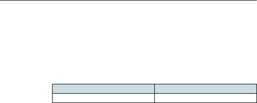
Figure1 FlexiZoneMicroBTS(FWHR)interfacepanel
RF
BACKHAUL
STATUS
BHC
BHB
AC
POWER
BLUETOOTH
InterfacepanelsideofBTS
WhenselectingalocationtomounttheBTS,keepinmindthefollowing:
InstallingandCablingFlexiZoneMicroHighPower
2x20WBTS
InstallingFlexiZoneMicroBTS
Issue:02 DN09229011 9

•AvoidmountingtheBTSsuchthattheantennasareblockedbyotherstructuressuch
aswalls.Adirectlineofsighttotheareatobecoveredwillprovidethebest
performance.
•Keepothermetallicmountingfeaturesasfarawayfromallantennasaspossible.
•KeepcablesroutedandsecuredawayfromtheLTEandBluetoothantennas.
•RemotelylocatingtheBluetoothantennaisnotallowed.
•Sinceonlyremotelyconnectedantennasaresupported,externallightningsurge
protectionmustbeadded.Formoreinformationonremotelymountingantennas,see
sectionInstallingantennas.
Ifsideclearanceislessthanscrewdriverlength,thegroundingcableneedstobepre-
installed.TheminimumandrecommendedmaintenanceclearancesareshowninTable
2:FlexiZoneMicroBTS(FWHR)maintenanceclearances.
Table2 FlexiZoneMicroBTS(FWHR)maintenanceclearances
BTS side Minimum clearances Recommended clearances
Front 50mm(1.97in) 500mm(19.68in)
Rear 35mm(1.38in)(1) 35mm(1.38in)(1)
Top 100mm(3.94in) Heightoftheunit+10mm
(0.39in)
Bottom 100mm(3.94in) 300mm(11.81in)
Left 10mm(0.39in)(2) 10mm(0.39in)(2)
Right 10mm(0.39in) 10/110mm(0.39/4.33in)(3)
(1)Forwallandpoleinstallations.
(2)Forhorizontalpoleinstallationstheclearancemustbeatleast20mm(0.78in).
(3)Dependsonthescrewdriverlength.
InstallingFlexiZoneMicroBTS InstallingandCablingFlexiZoneMicroHighPower
2x20WBTS
10 DN09229011 Issue:02

Figure2 FlexiZoneMicroBTSclearances
Right
Front
Rear
Bottom
Top
Left
Procedure
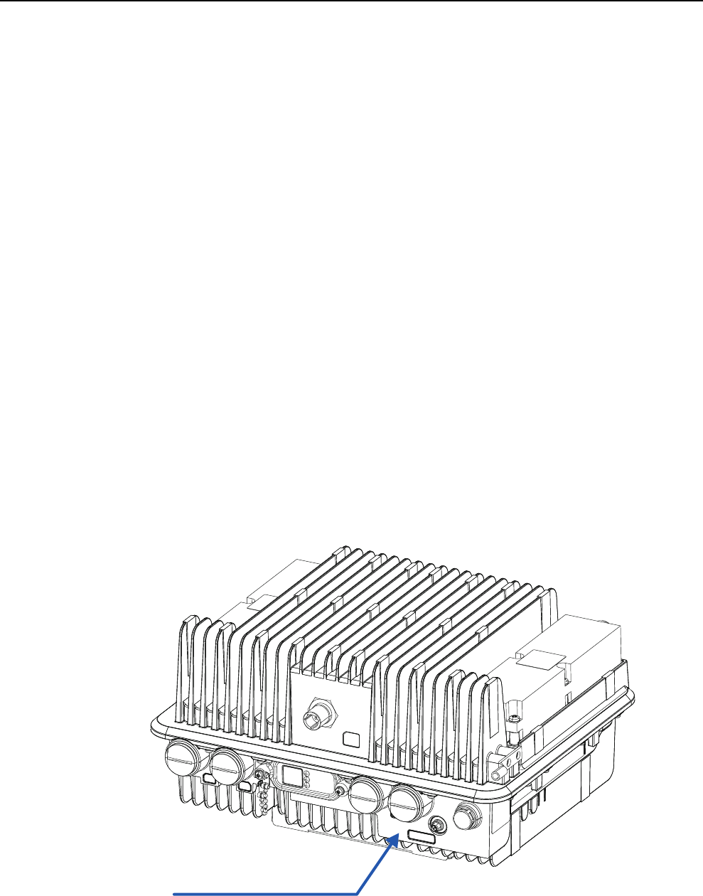
1 Disassemble the mounting bracket.
Themountingbracketconsistsoftwoelements:theinterfacebracketandstatic
bracket.Loosenthetwothumbscrews(M6),slideuptheinterfacebracketandput
asidethestaticbracket.Notethatthumbscrews(M6)areintegralpartsofthe
interfacebracket.
InstallingandCablingFlexiZoneMicroHighPower
2x20WBTS
InstallingFlexiZoneMicroBTS
Issue:02 DN09229011 11
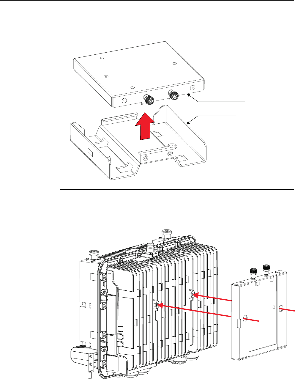
Figure3 Disassemblingthemountingbracket
Interfacebracket
Staticbracket
2 Fix the interface bracket to the Flexi Zone Micro BTS using two M6 cap screws
and washers included with the mounting bracket.
Tightenthescrewsto5.1Nm(3.8ft-lb).
Figure4 Fixingtheinterfacebracket
InstallingFlexiZoneMicroBTS InstallingandCablingFlexiZoneMicroHighPower
2x20WBTS
12 DN09229011 Issue:02
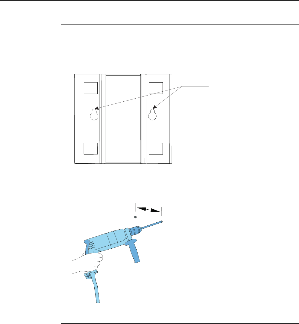
3 Mark the mounting screw locations on the wall and drill the holes for the
screws.
tTip: Usethestaticmountingbracketkeyholesasatemplate.
Figure5 Staticmountingbracketkeyholes
Keyholesfor
drilltemplate
Figure6 Drillingtheholes
115
(4.53in.)
mm
4 Fix the mounting bolts to the wall, and install the static mounting bracket on
the wall.
ThestaticmountingbracketkeyholesaredesignedtosuitM6screws.
Checkthatthebracketislevel.
InstallingandCablingFlexiZoneMicroHighPower
2x20WBTS
InstallingFlexiZoneMicroBTS
Issue:02 DN09229011 13
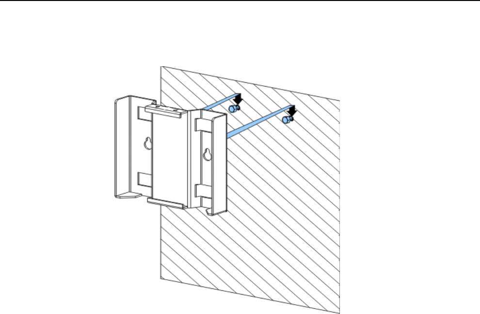
Figure7 Installingthestaticmountingbracketonthewall
InstallingFlexiZoneMicroBTS InstallingandCablingFlexiZoneMicroHighPower
2x20WBTS
14 DN09229011 Issue:02
5 Tighten the bracket’s fastener according to the manufacturer’s instructions.
6 Install the BTS to the static mounting bracket.
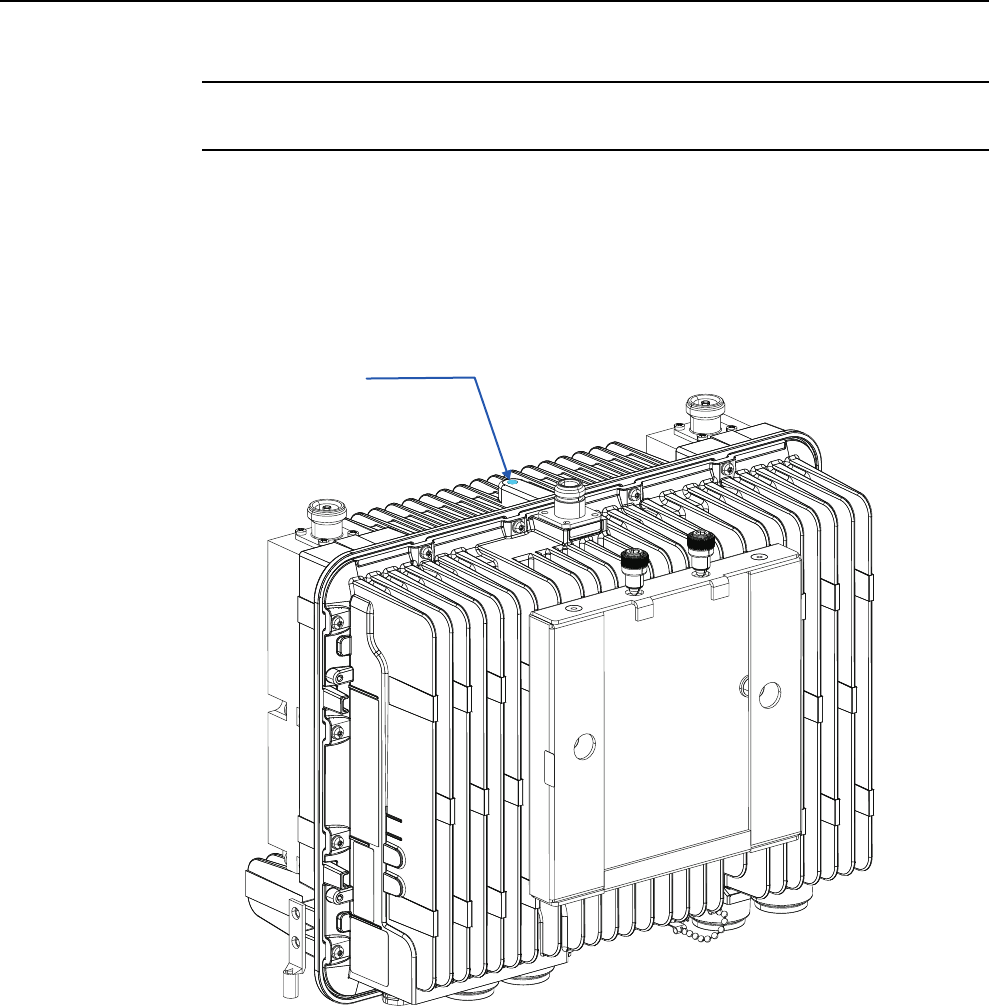
wNOTICE:Ifyoulifttheunitwitharope,useanM6sizeeyeboltwithaM6x1.0thread.
TheeyeboltshouldbefixedtothetopoftheBTS,inplaceoftherubberplug.The
eyeboltshouldberemovedandreplacedwiththerubberplugafterinstallingtheBTS.
Theeyeboltisnotpartofthedeliveryandmustbeorderedseparately.
Figure8 Rubberpluglocation
Rubberplug
a) PositiontheBTSwiththeinterfacebracketaligneddirectlyabovethestatic
mountingbracket.
b) SlidedowntheBTSuntilitisfullylocatedandseatedontothestaticbracket.
c) Handstartthethumbscrews(M6)tosecureBTStostaticbracket.
d) TorqueallM6screwsto5.1Nm(3.8ft-lb).
InstallingandCablingFlexiZoneMicroHighPower
2x20WBTS
InstallingFlexiZoneMicroBTS
Issue:02 DN09229011 15
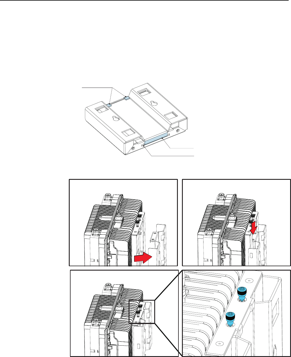
gNote: Beforetighteningthescrewsmakesurethat:
•thestaticmountingbracketissecurelycaptivatedintheinterfacebracket'sslot.
•tabsontheinterfacebracketarecaptivatedbythebacksurfaceofthestatic
mountingbracket.
Figure9 Correctbracketalignment
Tabson
interfacebracket
Tabon
staticbracket
Slotininterfacebracket
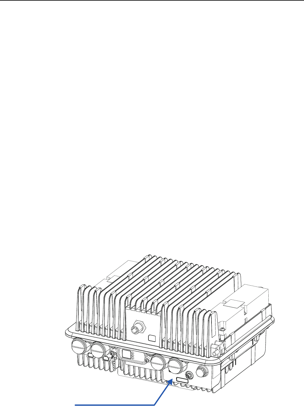
Figure10 InstallingtheBTSonawall
InstallingFlexiZoneMicroBTS InstallingandCablingFlexiZoneMicroHighPower
2x20WBTS
16 DN09229011 Issue:02
1.2 Installing Flexi Zone Micro BTS (FWHR) on a
vertical pole
TheproceduredescribestheinstallationonaverticalpolethatisspecificforFWHR.
Purpose
UsetheFlexiZoneWallandPoleMountingBracket(FMWA)(472858A)andbandstraps
toinstallFlexiZoneMicroBTSonapole.Thebandstrapsdependonthechosenpole
diameter.Thewidthofthebandstrapsshouldbelessthan¾"toproperlyfitintotheslots
ofthemountingbracket.
Before you start
fCAUTION! Risk of personal injury.
Ensurethattheselectedbandstrapscansustainthedeviceunderrequired
circumstances.
Theselectedbandstrapsshouldberatedforoutdooruseandbecapableofsecuring
theBTSweight.Acertifiedstructuralengineershouldinspectandapprovethe
mountingpoleandhardwarepriortoinstallation.
wNOTICE:FlexiZoneMicroBTSequipmentmustbeinstalledbytrainedandqualified
servicepersonnelinaccordancewithalllocalcodesandrequirements.
wNOTICE:FlexiZoneMicroBTSequipmentisintendedforinstallationinarestricted
accesslocationorequivalent.
wNOTICE:TheBTSinterfacepanelshouldalwaysfacetheground.Anyotherinstallation
positionmightcauseoverheatingandpossibledamagetotheBTS.
Figure11 FlexiZoneMicroBTS(FWHR)interfacepanel
RF
BACKHAUL
STATUS
BHC
BHB
AC
POWER
BLUETOOTH
InterfacepanelsideofBTS
InstallingandCablingFlexiZoneMicroHighPower
2x20WBTS
InstallingFlexiZoneMicroBTS
Issue:02 DN09229011 17

gNote: Thebandstrapsarenotpartofthedeliveryandmustbeorderedseparately.
WhenselectingalocationtomounttheBTS,keepinmindthefollowing:
•AvoidmountingtheBTSsuchthattheantennasareblockedbyotherstructuressuch
aswalls.Adirectlineofsighttotheareatobecoveredwillprovidethebest
performance.
•Keepothermetallicmountingfeaturesasfarawayfromallantennasaspossible.
•KeepcablesroutedandsecuredawayfromtheLTEandBluetoothantennas.
•RemotelylocatingtheBluetoothantennaisnotallowed.
•Sinceonlyremotelyconnectedantennasaresupported,externallightningsurge
protectionmustbeadded.Formoreinformationonremotelymountingantennas,see
sectionInstallingantennas.
Ifsideclearanceislessthanscrewdriverlength,thegroundingcableneedstobepre-
installed.TheminimumandrecommendedmaintenanceclearancesareshowninTable
2:FlexiZoneMicroBTS(FWHR)maintenanceclearances.
Table3 FlexiZoneMicroBTS(FWHR)maintenanceclearances
BTS side Minimum clearances Recommended clearances
Front 50mm(1.97in) 500mm(19.68in)
Rear 35mm(1.38in)(1) 35mm(1.38in)(1)
Top 100mm(3.94in) Heightoftheunit+10mm
(0.39in)
Bottom 100mm(3.94in) 300mm(11.81in)
Left 10mm(0.39in)(2) 10mm(0.39in)(2)
Right 10mm(0.39in) 10/110mm(0.39/4.33in)(3)
(1)Forwallandpoleinstallations.
(2)Forhorizontalpoleinstallationstheclearancemustbeatleast20mm(0.78in).
(3)Dependsonthescrewdriverlength.
InstallingFlexiZoneMicroBTS InstallingandCablingFlexiZoneMicroHighPower
2x20WBTS
18 DN09229011 Issue:02
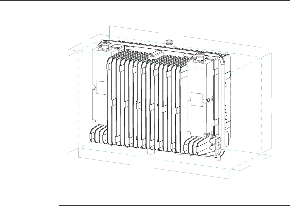
Figure12 FlexiZoneMicroBTSclearances
Right
Front
Rear
Bottom
Top
Left
Procedure
1 Disassemble the mounting bracket.
Themountingbracketconsistsoftwoelements:theinterfacebracketandstatic
bracket.Loosenthetwothumbscrews(M6),slideuptheinterfacebracketandput
asidethestaticbracket.Notethatthumbscrews(M6)areintegralpartsofthe
interfacebracket.
InstallingandCablingFlexiZoneMicroHighPower
2x20WBTS
InstallingFlexiZoneMicroBTS
Issue:02 DN09229011 19

Figure13 Disassemblingthemountingbracket
Interfacebracket
Staticbracket
2 Fix the interface bracket to the Flexi Zone Micro BTS using two M6 cap screws
and washers included with the mounting bracket.
Tightenthescrewsto5.1Nm(3.8ft-lb).
Figure14 Fixingtheinterfacebracket
InstallingFlexiZoneMicroBTS InstallingandCablingFlexiZoneMicroHighPower
2x20WBTS
20 DN09229011 Issue:02
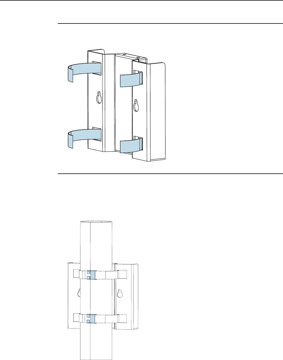
3 Thread the straining straps to the static mounting bracket.
Figure15 Threadingthestrainingstraps
4 Install the static mounting bracket to the pole with the straining straps.
gNote: Thestrapsshouldbetightenedandsecuredaccordingtothestrap
manufacturer’sinstructionsandthebracketshouldbesecureandimmovable.
Figure16 Installingtheinstallationplatetothepole
InstallingandCablingFlexiZoneMicroHighPower
2x20WBTS
InstallingFlexiZoneMicroBTS
Issue:02 DN09229011 21

5 Tighten the straining straps around the pole.
6 Install the BTS to the static mounting bracket.
wNOTICE:Ifyoulifttheunitwitharope,useanM6sizeeyeboltwithaM6x1.0thread.
TheeyeboltshouldbefixedtothetopoftheBTS,inplaceoftherubberplug.The
eyeboltshouldberemovedandreplacedwiththerubberplugafterinstallingtheBTS.
Theeyeboltisnotpartofthedeliveryandmustbeorderedseparately.
Figure17 Rubberpluglocation
Rubberplug
a) PositiontheBTSwiththeinterfacebracketaligneddirectlyabovethestatic
mountingbracket.
b) SlidedowntheBTSuntilitisfullylocatedandseatedontothestaticbracket.
c) Handstartthethumbscrews(M6)tosecuretheBTStothestaticbracket.
d) TorqueallM6screwsto5.1Nm(3.8ft-lb).
InstallingFlexiZoneMicroBTS InstallingandCablingFlexiZoneMicroHighPower
2x20WBTS
22 DN09229011 Issue:02

gNote: Beforetighteningthescrewsmakesurethat:
•thestaticmountingbracketissecurelycaptivatedintheslotintheinterfacebracket.
•tabsontheinterfacebracketarecaptivatedbythebacksurfaceofthestatic
mountingbracket.
Figure18 Correctbracketalignment
Tabson
interfacebracket
Tabon
staticbracket
Slotininterfacebracket
Figure19 InstallingtheBTSonaverticalpole
InstallingandCablingFlexiZoneMicroHighPower
2x20WBTS
InstallingFlexiZoneMicroBTS
Issue:02 DN09229011 23

1.3 Installing Flexi Zone Micro BTS (FWHR) on a
horizontal pole
TheproceduredescribestheinstallationonahorizontalpolethatisspecificforFWHR.
Purpose
UsetheFlexiZoneWallandPoleMountingBracket(FMWA)(472858A)andbandstraps
toinstallFlexiZoneMicroBTSonapole.Thebandstrapsdependonthechosenpole
diameter.Thewidthofthebandstrapsshouldbelessthan¾"toproperlyfitintotheslots
ofthemountingbracket.
Before you start
fCAUTION! Risk of personal injury.
Ensurethattheselectedbandstrapscansustainthedeviceunderrequired
circumstances.
Theselectedbandstrapsshouldberatedforoutdooruseandbecapableofsecuring
theBTSweight.Acertifiedstructuralengineershouldinspectandapprovethe
mountingpoleandhardwarepriortoinstallation.
wNOTICE:FlexiZoneMicroBTSequipmentmustbeinstalledbytrainedandqualified
servicepersonnelinaccordancewithalllocalcodesandrequirements.
wNOTICE:FlexiZoneMicroBTSequipmentisintendedforinstallationinarestricted
accesslocationorequivalent.
wNOTICE:TheBTSinterfacepanelshouldalwaysfacetheground.Anyotherinstallation
positionmightcauseoverheatingandpossibledamagetotheBTS.
Figure20 FlexiZoneMicroBTS(FWHR)interfacepanel
RF
BACKHAUL
STATUS
BHC
BHB
AC
POWER
BLUETOOTH
InterfacepanelsideofBTS
InstallingFlexiZoneMicroBTS InstallingandCablingFlexiZoneMicroHighPower
2x20WBTS
24 DN09229011 Issue:02

gNote: Thebandstrapsarenotpartofthedeliveryandmustbeorderedseparately.
WhenselectingalocationtomounttheBTS,keepinmindthefollowing:
•AvoidmountingtheBTSsuchthattheantennasareblockedbyotherstructuressuch
aswalls.Adirectlineofsighttotheareatobecoveredwillprovidethebest
performance.
•Keepothermetallicmountingfeaturesasfarawayfromallantennasaspossible.
•KeepcablesroutedandsecuredawayfromtheLTEandBluetoothantennas.
•RemotelylocatingtheBluetoothantennaisnotallowed.
•Sinceonlyremotelyconnectedantennasaresupported,externallightningsurge
protectionmustbeadded.Formoreinformationonremotelymountingantennas,see
sectionInstallingantennas.
Ifsideclearanceislessthanscrewdriverlength,thegroundingcableneedstobepre-
installed.TheminimumandrecommendedmaintenanceclearancesareshowninTable
2:FlexiZoneMicroBTS(FWHR)maintenanceclearances.
Table4 FlexiZoneMicroBTS(FWHR)maintenanceclearances
BTS side Minimum clearances Recommended clearances
Front 50mm(1.97in) 500mm(19.68in)
Rear 35mm(1.38in)(1) 35mm(1.38in)(1)
Top 100mm(3.94in) Heightoftheunit+10mm
(0.39in)
Bottom 100mm(3.94in) 300mm(11.81in)
Left 10mm(0.39in)(2) 10mm(0.39in)(2)
Right 10mm(0.39in) 10/110mm(0.39/4.33in)(3)
(1)Forwallandpoleinstallations.
(2)Forhorizontalpoleinstallationstheclearancemustbeatleast20mm(0.78in).
(3)Dependsonthescrewdriverlength.
InstallingandCablingFlexiZoneMicroHighPower
2x20WBTS
InstallingFlexiZoneMicroBTS
Issue:02 DN09229011 25
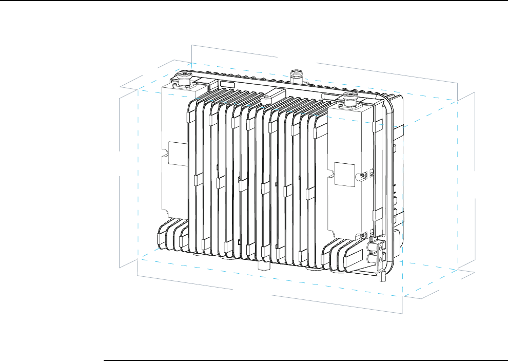
Figure21 FlexiZoneMicroBTSclearances
Right
Front
Rear
Bottom
Top
Left
Procedure
1 Disassemble the mounting bracket.
Themountingbracketconsistsoftwoelements:theinterfacebracketandstatic
bracket.Loosenthetwothumbscrews(M6),slideuptheinterfacebracketandput
asidethestaticbracket.Notethatthumbscrews(M6)areintegralpartsofthe
interfacebracket.
InstallingFlexiZoneMicroBTS InstallingandCablingFlexiZoneMicroHighPower
2x20WBTS
26 DN09229011 Issue:02
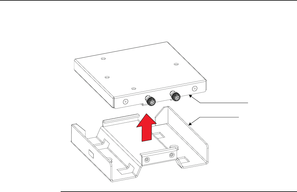
Figure22 Disassemblingthemountingbracket
Interfacebracket
Staticbracket
2 Fix the interface bracket to the Flexi Zone Micro BTS using two M6 cap screws
and washers included with the mounting bracket.
Tightenthescrewsto5.1Nm(3.8ft-lb).
InstallingandCablingFlexiZoneMicroHighPower
2x20WBTS
InstallingFlexiZoneMicroBTS
Issue:02 DN09229011 27
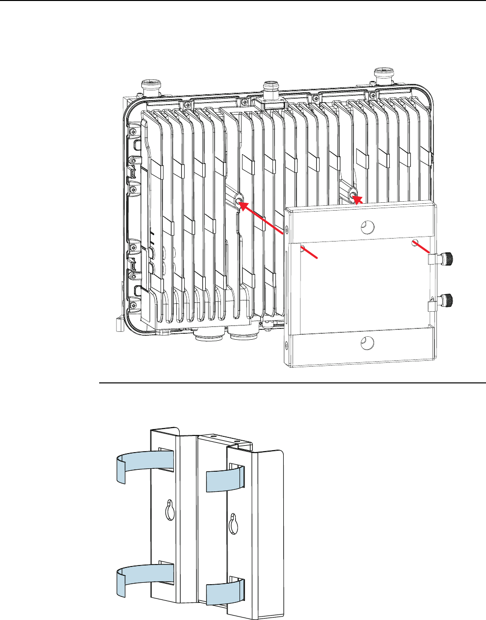
Figure23 Fixingtheinterfacebracket
3 Thread the straining straps to the static mounting bracket.
Figure24 Threadingthestrainingstraps
InstallingFlexiZoneMicroBTS InstallingandCablingFlexiZoneMicroHighPower
2x20WBTS
28 DN09229011 Issue:02
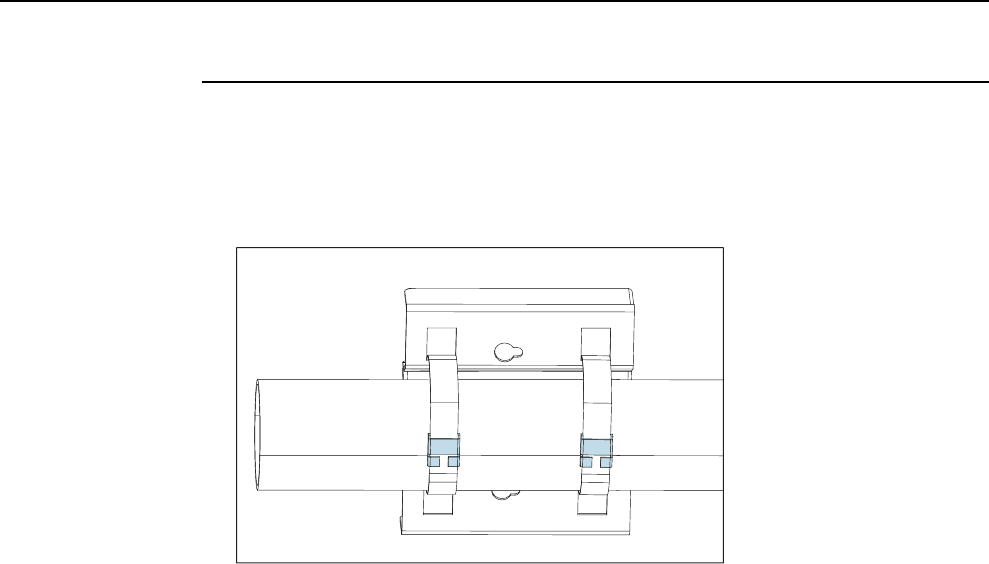
4 Install the static mounting bracket on the pole with the straining straps.
gNote: Thestrapsshouldbetightenedandsecuredaccordingtothestrap
manufacturer’sinstructionsandthebracketshouldbesecureandimmovable.
Figure25 Installingthestaticmountingbracketonthepole
InstallingandCablingFlexiZoneMicroHighPower
2x20WBTS
InstallingFlexiZoneMicroBTS
Issue:02 DN09229011 29