Nokia Solutions and Networks HVTP-01 PCS Micro Base Station User Manual dn9913471x1x2xen
Nokia Solutions and Networks PCS Micro Base Station dn9913471x1x2xen
Contents
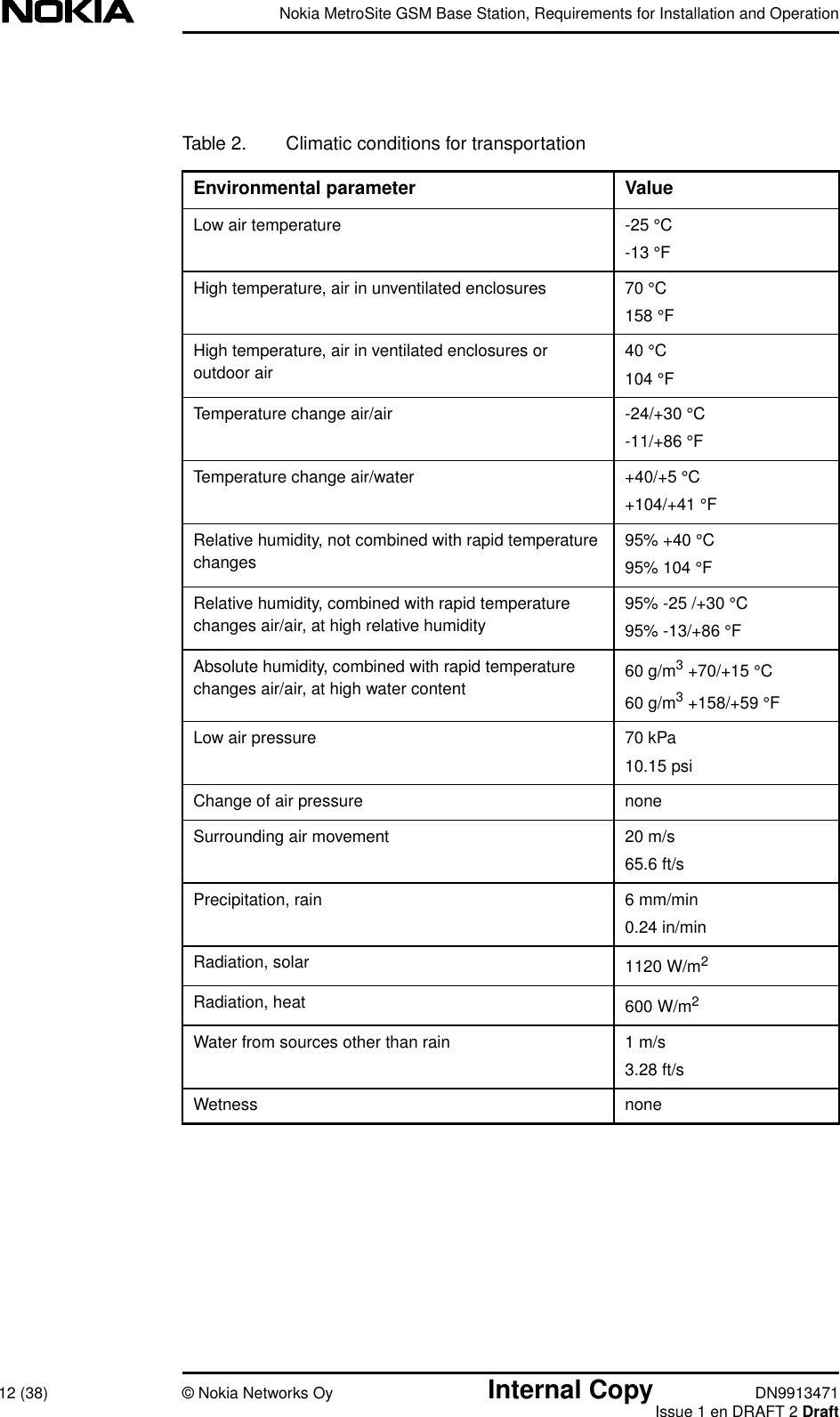
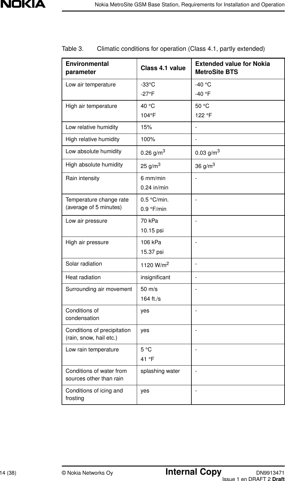
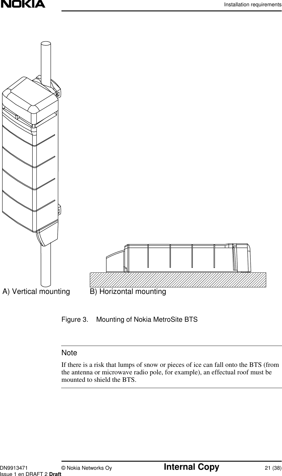
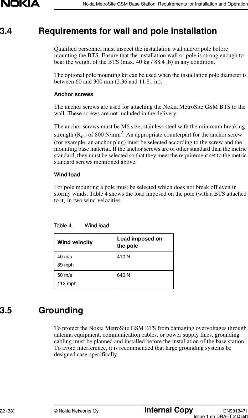
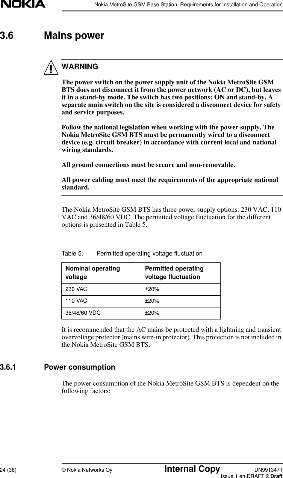
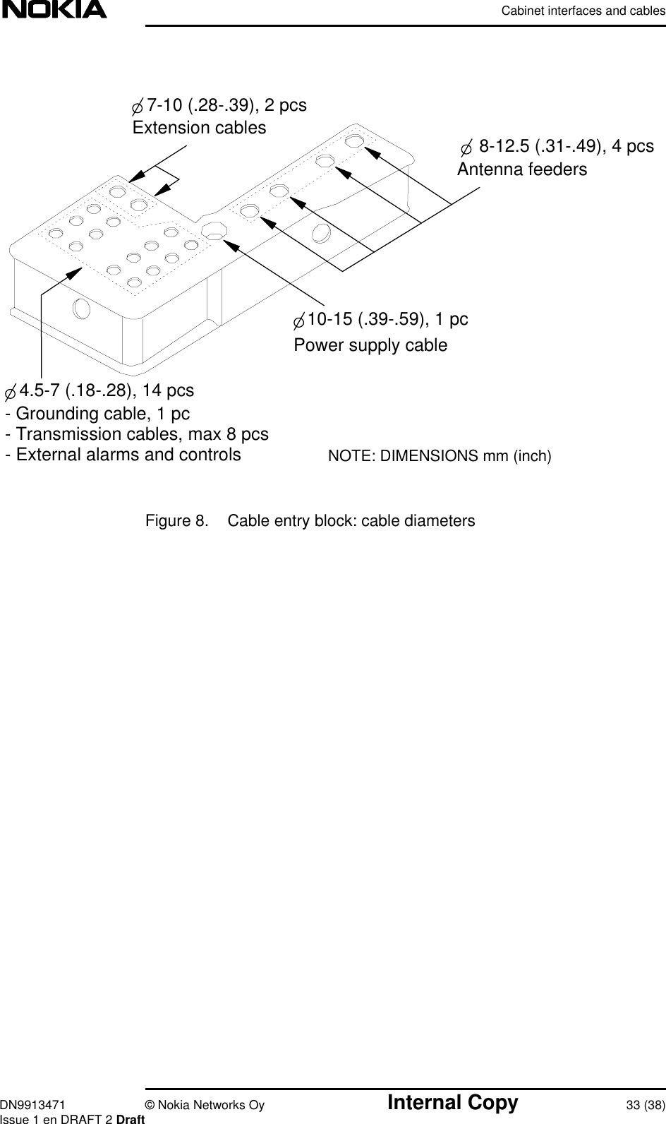
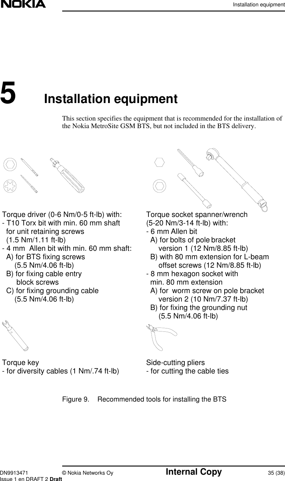
- 1. install and operation manual
- 2. USERSMANUAL AMENDMENT
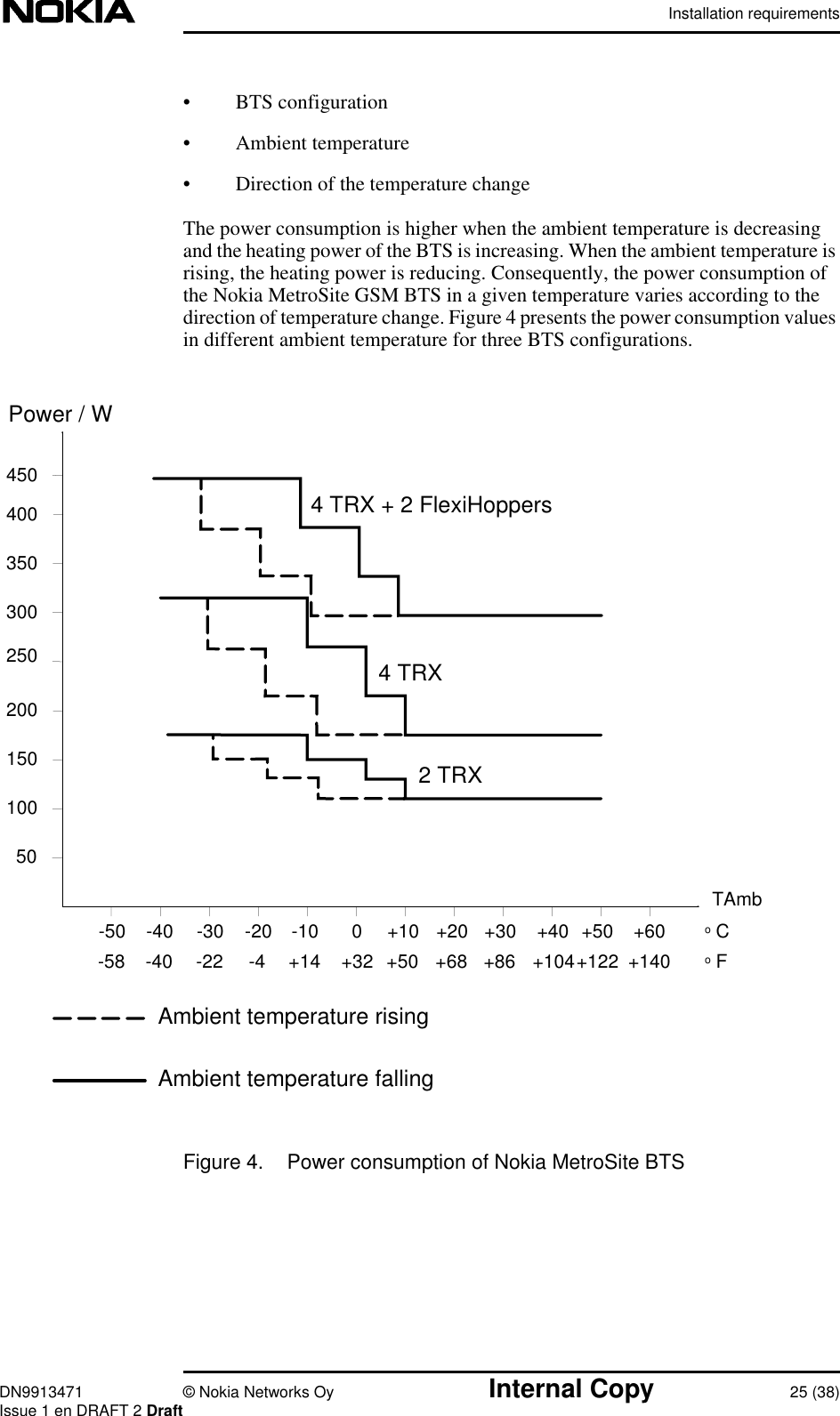
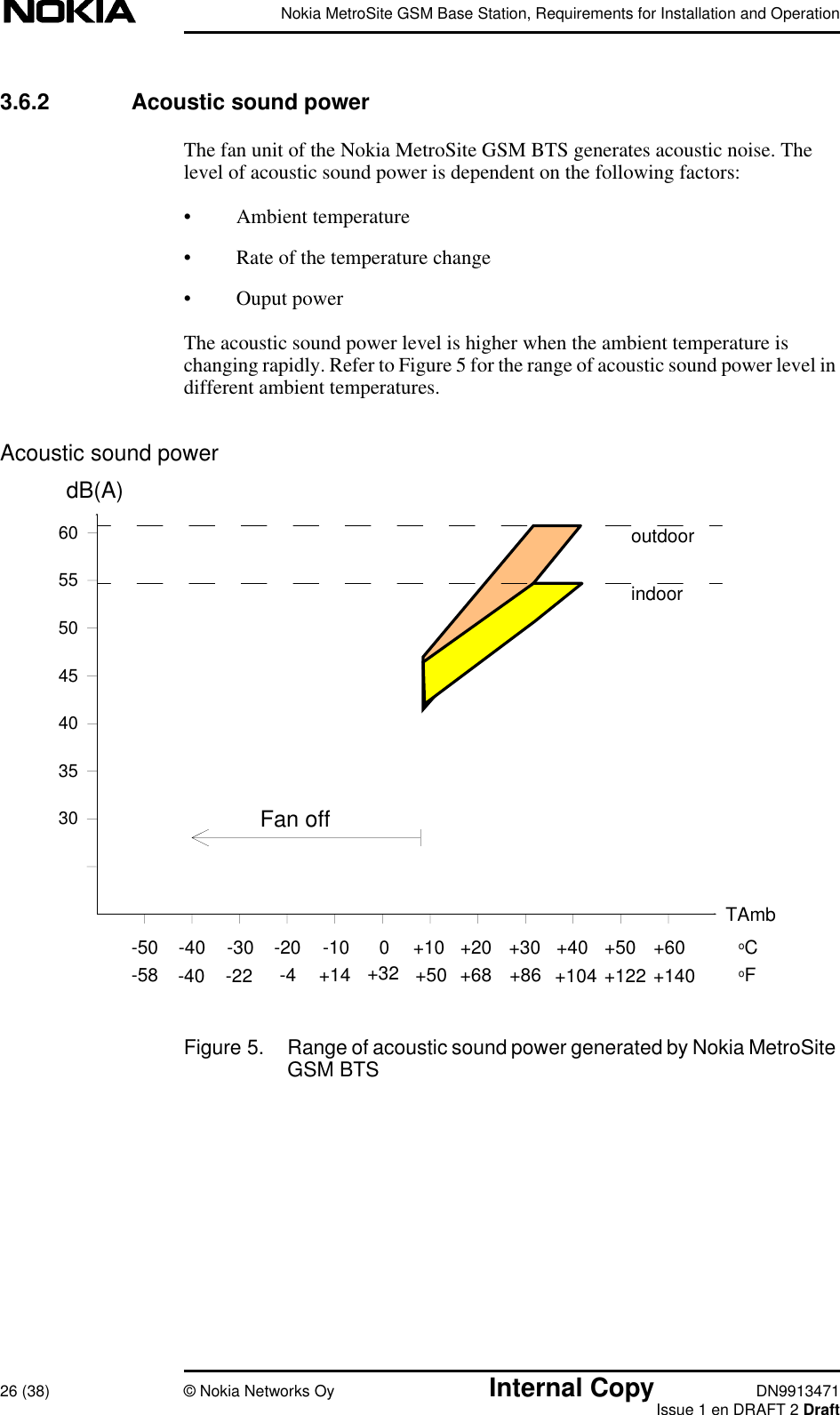
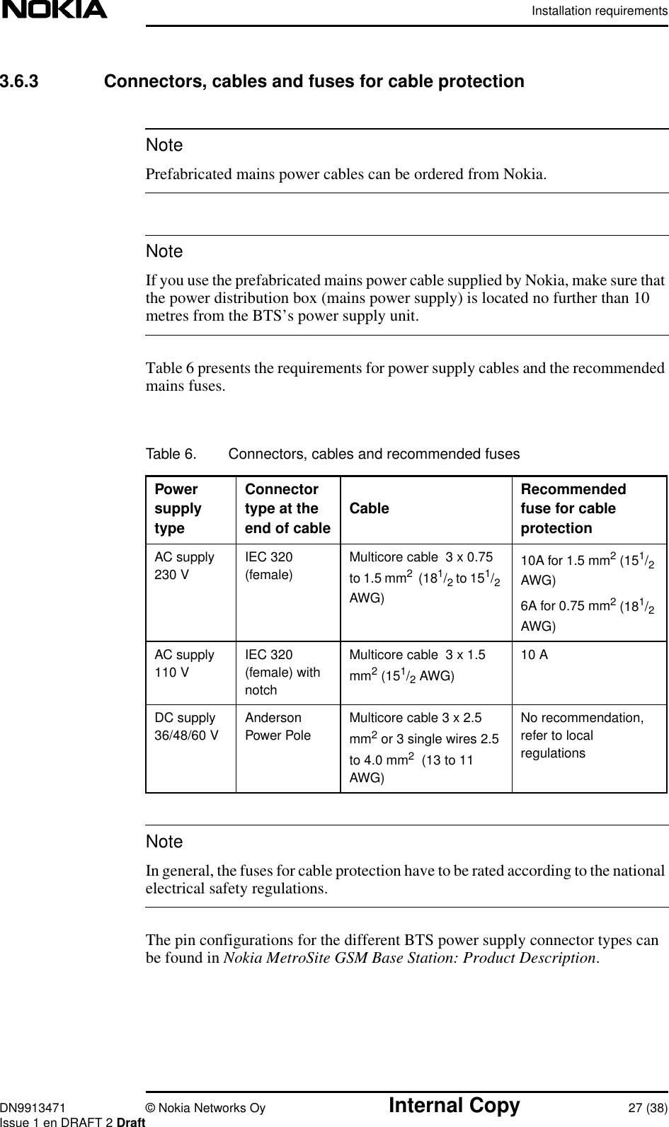
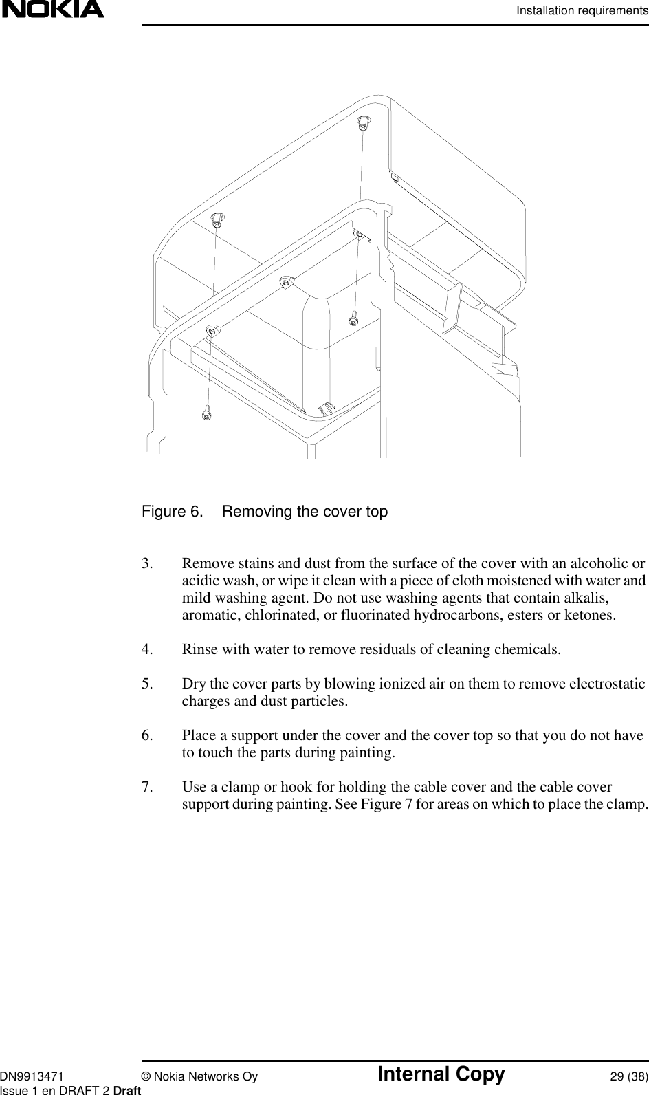
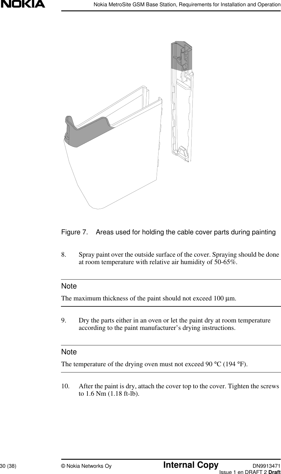
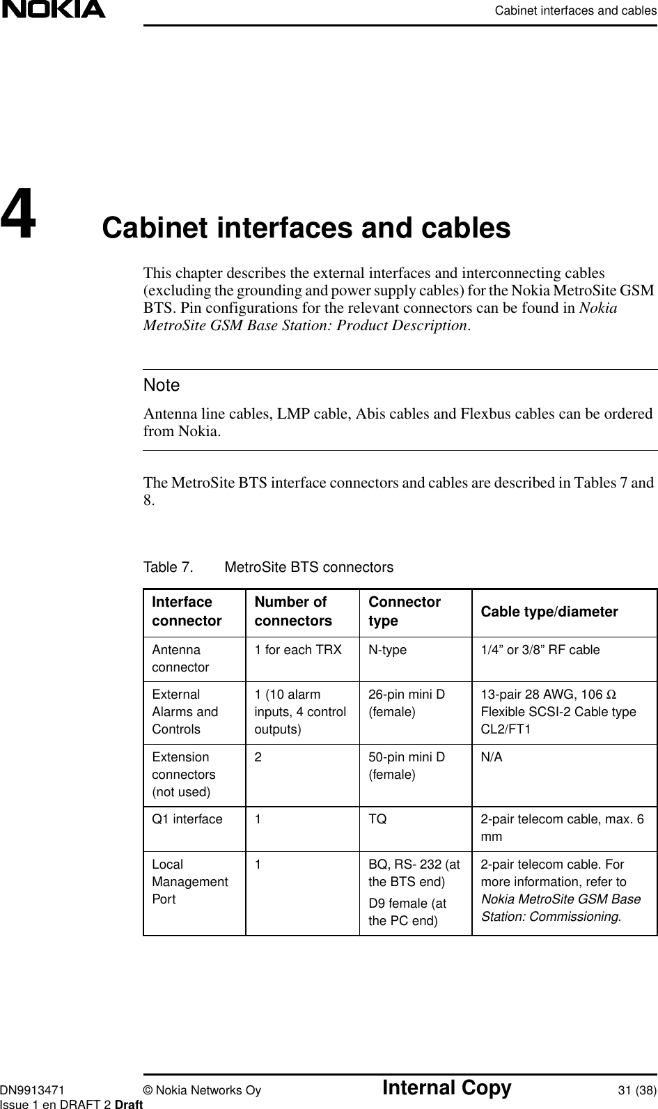
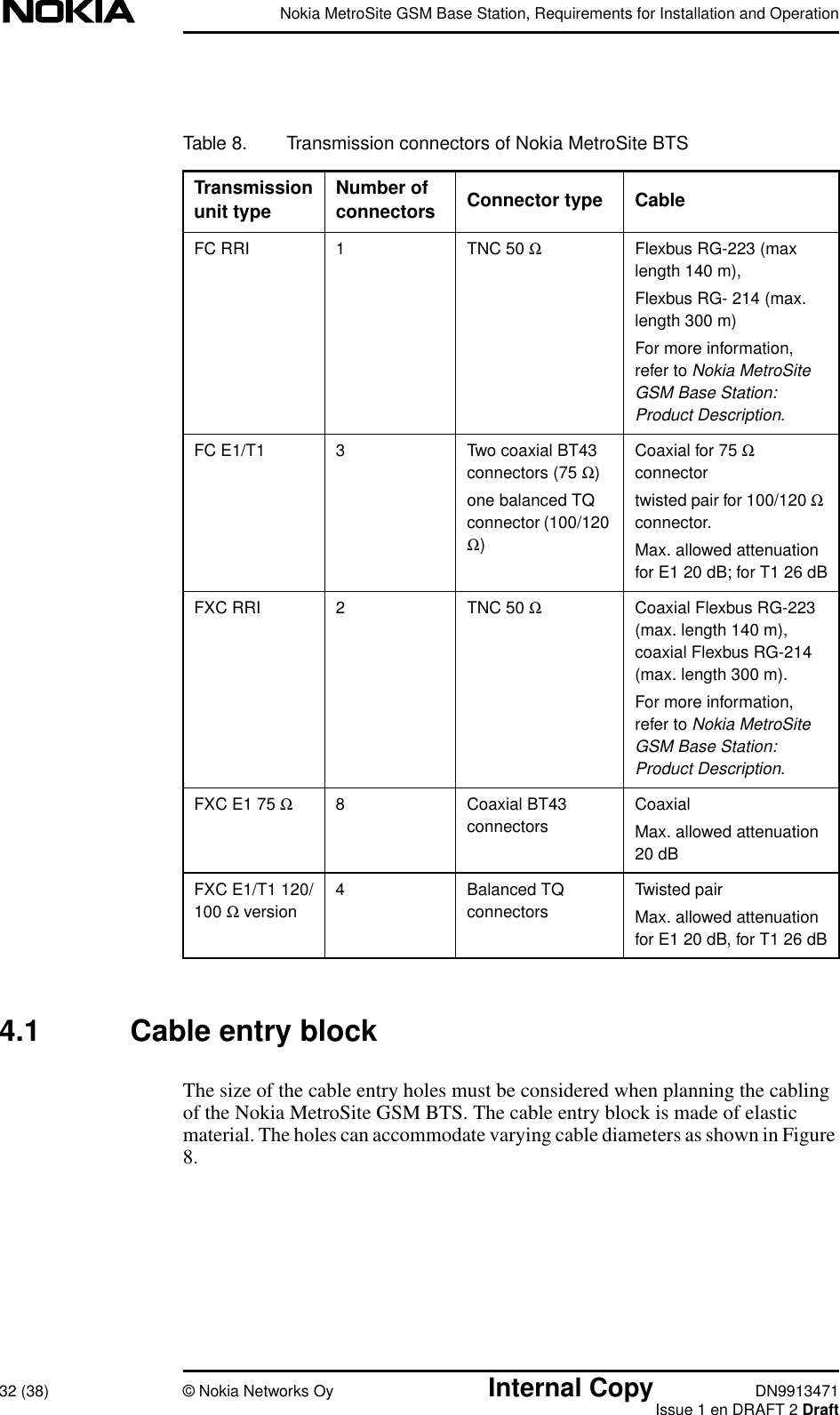
install and operation manual