Nokia Solutions and Networks HVTP-01 PCS Micro Base Station User Manual dn9913471x1x2xen
Nokia Solutions and Networks PCS Micro Base Station dn9913471x1x2xen
Contents
- 1. install and operation manual
- 2. USERSMANUAL AMENDMENT
install and operation manual
DN9913471 © Nokia Networks Oy Internal Copy 1 (38)
Issue 1 en DRAFT 2 Draft
Nokia MetroSite GSM Base
Station, Requirements for
Installation and Operation
Nokia MetroSite GSM Base Station, Requirements for Installation and Operation
2 (38) © Nokia Networks Oy Internal Copy DN9913471
Issue 1 en DRAFT 2 Draft
The information in this document is subject to change without notice and describes only the
product defined in the introduction of this documentation. This document is intended for the
use of Nokia Networks' customers only for the purposes of the agreement under which the
document is submitted, and no part of it may be reproduced or transmitted in any form or
means without the prior written permission of Nokia Networks. The document has been
prepared to be used by professional and properly trained personnel, and the customer
assumes full responsibility when using it. Nokia Networks welcomes customer comments as
part of the process of continuous development and improvement of the documentation.
The information or statements given in this document concerning the suitability, capacity, or
performance of the mentioned hardware or software products cannot be considered binding
but shall be defined in the agreement made between Nokia Networks and the customer.
However, Nokia Networks has made all reasonable efforts to ensure that the instructions
contained in the document are adequate and free of material errors and omissions. Nokia
Networks will, if necessary, explain issues which may not be covered by the document.
Nokia Networks' liability for any errors in the document is limited to the documentary correction
of errors. Nokia Networks WILL NOT BE RESPONSIBLE IN ANY EVENT FOR ERRORS IN
THIS DOCUMENT OR FOR ANY DAMAGES, INCIDENTAL OR CONSEQUENTIAL
(INCLUDING MONETARY LOSSES), that might arise from the use of this document or the
information in it.
This document and the product it describes are considered protected by copyright according to
the applicable laws.
NOKIA logo is a registered trademark of Nokia Corporation.
Other product names mentioned in this document may be trademarks of their respective
companies, and they are mentioned for identification purposes only.
Copyright © Nokia Networks Oy 2000. All rights reserved.
As stated in the Declaration of Conformity, this product complies with protection requirements
of the Council Directive 89/336/EEC relating to electromagnetic compatibility, when installed
using EMC-protected installation practices and practices stated in our User Manuals.

DN9913471 © Nokia Networks Oy Internal Copy 3 (38)
Issue 1 en DRAFT 2 Draft
Contents
Contents 3
1 About this document 7
2 Environment 9
2.1 Storage 9
2.1.1 International standard for storage 9
2.1.2 Climatic conditions for storage 9
2.1.3 Mechanical conditions for storage 10
2.2 Transportation 11
2.2.1 International standard for transportation 11
2.2.2 Climatic conditions for transportation 11
2.2.3 Mechanical conditions for transportation 13
2.3 Operation 13
2.3.1 International standard for operation 13
2.3.2 Climatic conditions for operation 13
2.3.3 Mechanical conditions for operation 15
2.3.4 Ingress protection 15
2.3.5 Acoustic noise 15
2.3.6 EMC shielding 15
2.3.7 Safety 15
3 Installation requirements 17
3.1 Checking the site 17
3.2 Space requirements 17
3.2.1 Nokia MetroSite BTS dimensions and weight 18
3.2.2 Clearances around BTS 18
3.3 Mounting locations and positions 20
3.4 Requirements for wall and pole installation 22
3.5 Grounding 22
3.6 Mains power 24
3.6.1 Power consumption 24
3.6.2 Acoustic sound power 26
3.6.3 Connectors, cables and fuses for cable protection 27
3.7 Painting the BTS cover 28
4 Cabinet interfaces and cables 31
4.1 Cable entry block 32
5 Installation equipment 35
Index 37

Nokia MetroSite GSM Base Station, Requirements for Installation and Operation
4 (38) © Nokia Networks Oy Internal Copy DN9913471
Issue 1 en DRAFT 2 Draft
DN9913471 © Nokia Networks Oy Internal Copy 5 (38)
Issue 1 en DRAFT 2 Draft
Summary of changes
Version 1, 12th November 1999.
Pilot 3 (Version 1.2), 6th April 2000:
• Added GSM to title and to body text
• Added CE marking
• Changed acoustic noise to 61dB in Chapters 2.3.5, 3.6.2 and Figure 5
• Increased cabinet length to 870mm in Figures 1 and 2.

Nokia MetroSite GSM Base Station, Requirements for Installation and Operation
6 (38) © Nokia Networks Oy Internal Copy DN9913471
Issue 1 en DRAFT 2 Draft

About this document
DN9913471 © Nokia Networks Oy Internal Copy 7 (38)
Issue 1 en DRAFT 2 Draft
1About this document
This document introduces the requirements set by the Nokia MetroSite GSM
Base Station (BTS) for successful installation and operation. Use this document
as the source for the following information needed in the planning of installation:
• Specification on the environmental conditions during transportation,
storage and operation
• Space requirements and other site-related installation matters
• Site grounding and power supply to the BTS
• Interface connections
• Installation tools
Read also Nokia MetroSite GSM Base Station: Warnings and Cautions in
conjunction with this document.
Nokia MetroSite GSM Base Station, Requirements for Installation and Operation
8 (38) © Nokia Networks Oy Internal Copy DN9913471
Issue 1 en DRAFT 2 Draft
Environment
DN9913471 © Nokia Networks Oy Internal Copy 9 (38)
Issue 1 en DRAFT 2 Draft
Caution
2Environment
This chapter defines the classes of environmental conditions and their severities
to which the Nokia MetroSite GSM BTS can be exposed. The information is
organised in the following parts:
• Conditions for Storage
• Conditions for Transportation
• Conditions for Operation
2.1 Storage
This section defines the environmental conditions which the Nokia MetroSite
GSM BTS can be exposed to during storage.
The Nokia MetroSite GSM BTS must be stored in its original package before the
installation.
2.1.1 International standard for storage
According to the ETS 300 019-1-1:1992, the class for Nokia MetroSite BTS is
Class 1.2: weather-protected, partly temperature-controlled storage locations.
2.1.2 Climatic conditions for storage
The climatic conditions during the storage of the Nokia MetroSite GSM BTS are
presented in Table 1 (according to ETS 300 019-1-1:1992).
Nokia MetroSite GSM Base Station, Requirements for Installation and Operation
10 (38) © Nokia Networks Oy Internal Copy DN9913471
Issue 1 en DRAFT 2 Draft
2.1.3 Mechanical conditions for storage
The Nokia MetroSite GSM BTS complies with ETS 300 019-1-1:1992 class 1.2.
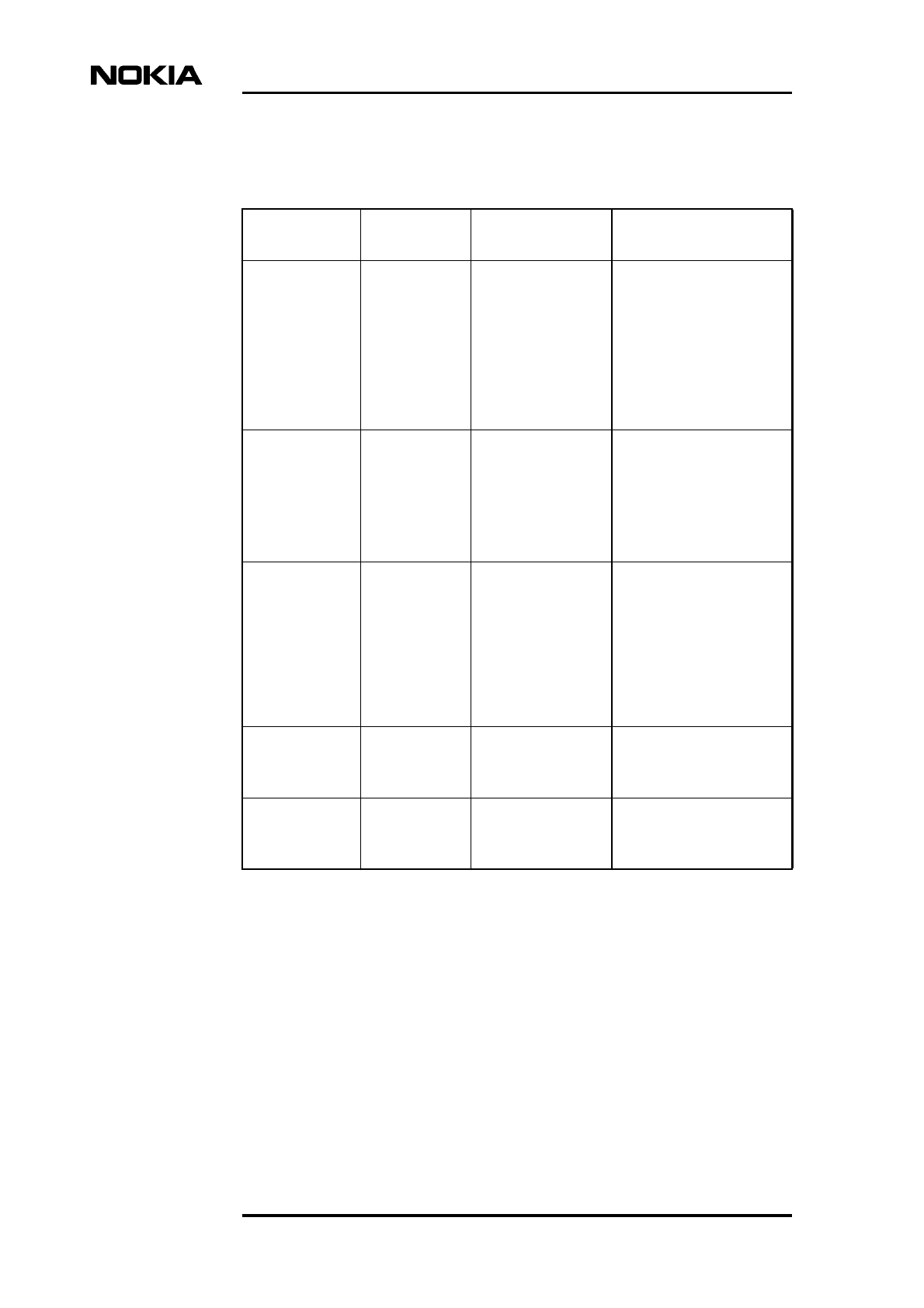
Table 1. Climatic conditions for storage
Environmental parameter Value
Low air temperature - 25 °C
- 13 °F
High air temperature 55 °C
131 °F
Low relative humidity 10%
High relative humidity 100%
Low absolute humidity 0.5 g/m3
High absolute humidity 29 g/m3
Rain intensity none
Temperature change rate (average of 5
minutes)
0.5 °C/min
0.9 °F/min
Low air pressure 70 kPa
10.15 psi
High air pressure 106 kPa
15.37 psi
Solar radiation 1120 W/m2
Surrounding air movement 30 m/s
98 ft/s
Conditions of condensation yes
Conditions of precipitation (rain, snow, hail,
etc.)
yes
Low rain temperature none
Conditions of water from sources other than
rain
dripping water
Conditions of icing and frosting yes
Environment
DN9913471 © Nokia Networks Oy Internal Copy 11 (38)
Issue 1 en DRAFT 2 Draft
Caution
Note
Note
2.2 Transportation
This section defines the environmental conditions which the Nokia MetroSite
GSM BTS can be exposed to during transportation.
The Nokia MetroSiteGSM BTS must be transported in its original package before
the installation.
The Nokia MetroSite GSM BTS is delivered to the customer with the ordered
plug-in units preinstalled.
2.2.1 International standard for transportation
According to ETS 300 019-1-2:1992, the class for the Nokia MetroSite GSM
BTS equipment is Class 2.2. This class applies to those cases of transportation
where special care has been taken, e.g. with respect to low temperature and
handling.
The typical transportation time is considered to be 30 days or less. When the total
transportation time exceeds 30 days, additional storage or packaging precautions
must be considered.
2.2.2 Climatic conditions for transportation
The climatic conditions during the transportation are presented in Table 2
(according to ETS 300 019-1-2:1992).
Nokia MetroSite GSM Base Station, Requirements for Installation and Operation
12 (38) © Nokia Networks Oy Internal Copy DN9913471
Issue 1 en DRAFT 2 Draft
Table 2. Climatic conditions for transportation
Environmental parameter Value
Low air temperature -25 °C
-13 °F
High temperature, air in unventilated enclosures 70 °C
158 °F
High temperature, air in ventilated enclosures or
outdoor air
40 °C
104 °F
Temperature change air/air -24/+30 °C
-11/+86 °F
Temperature change air/water +40/+5 °C
+104/+41 °F
Relative humidity, not combined with rapid temperature
changes
95% +40 °C
95% 104 °F
Relative humidity, combined with rapid temperature
changes air/air, at high relative humidity
95% -25 /+30 °C
95% -13/+86 °F
Absolute humidity, combined with rapid temperature
changes air/air, at high water content 60 g/m3 +70/+15 °C
60 g/m3 +158/+59 °F
Low air pressure 70 kPa
10.15 psi
Change of air pressure none
Surrounding air movement 20 m/s
65.6 ft/s
Precipitation, rain 6 mm/min
0.24 in/min
Radiation, solar 1120 W/m2
Radiation, heat 600 W/m2
Water from sources other than rain 1 m/s
3.28 ft/s
Wetness none
Environment
DN9913471 © Nokia Networks Oy Internal Copy 13 (38)
Issue 1 en DRAFT 2 Draft
Note
2.2.3 Mechanical conditions for transportation
For mechanical conditions during transportation, the Nokia MetroSite GSM BTS
complies with ETS 300 019 1-2:1992 class 2.2.
2.3 Operation
This section defines the environmental conditions during the operation of the
Nokia MetroSite GSM BTS at locations which are not protected from direct
weather influences.
When surveying the prospective sites, consider the values presented in this
section.
Operating conditions are defined as stationary: the equipment is mounted on a
structure, or on a mounting device, or it is permanently placed at a certain site.
The Nokia MetroSite GSM BTS is not intended for portable use.
2.3.1 International standard for operation
According to ETS 300 019-1-4:1992, the class for the Nokia MetroSite BGSM
TS equipment is class 4.1.
2.3.2 Climatic conditions for operation
For climatic conditions during operation, the Nokia MetroSite GSM BTS
complies generally with class 4.1 as presented in Table 3. However, for the
temperature and humidity values, the table presents extended operational climatic
conditions, which differ from class 4.1. The weather shielding of the Nokia
MetroSite GSM BTS is valid when the BTS is mounted in the recommended
positions.
Nokia MetroSite GSM Base Station, Requirements for Installation and Operation
14 (38) © Nokia Networks Oy Internal Copy DN9913471
Issue 1 en DRAFT 2 Draft
Table 3. Climatic conditions for operation (Class 4.1, partly extended)
Environmental
parameter Class 4.1 value Extended value for Nokia
MetroSite BTS
Low air temperature -33°C
-27°F
-40 °C
-40 °F
High air temperature 40 °C
104°F
50 °C
122 °F
Low relative humidity 15% -
High relative humidity 100% -
Low absolute humidity 0.26 g/m30.03 g/m3
High absolute humidity 25 g/m336 g/m3
Rain intensity 6 mm/min
0.24 in/min
-
Temperature change rate
(average of 5 minutes)
0.5 °C/min.
0.9 °F/min
-
Low air pressure 70 kPa
10.15 psi
-
High air pressure 106 kPa
15.37 psi
-
Solar radiation 1120 W/m2-
Heat radiation insignificant -
Surrounding air movement 50 m/s
164 ft./s
-
Conditions of
condensation
yes -
Conditions of precipitation
(rain, snow, hail etc.)
yes -
Low rain temperature 5 °C
41 °F
-
Conditions of water from
sources other than rain
splashing water -
Conditions of icing and
frosting
yes -

Environment
DN9913471 © Nokia Networks Oy Internal Copy 15 (38)
Issue 1 en DRAFT 2 Draft
2.3.3 Mechanical conditions for operation
For mechanical conditions during operation, the Nokia MetroSite GSM BTS
complies with ETS 300 019-1-4:1992 class 4.1.
2.3.4 Ingress protection
The electronic components inside the units of the Nokia MetroSite GSM BTS are
protected against the ingress of rain, snow and dust to the minumum level of IP55
of European standard EN 60529, and level 3R of UL standard 50.
2.3.5 Acoustic noise
The maximum acoustic noise generated by the Nokia MetroSite GSM BTS is 61
dB (A) in an outdoor environment and 55 dB (A) for an indoor environment. The
acoustic noise is measured according to ISO 3744. The noise is sound power.
2.3.6 EMC shielding
The chassis and the units of the Nokia MetroSite GSM BTS together provide the
EMC shielding. The EMC shielding complies to the requirements set by the
following standards:
• GSM 11.21
• ETS 300, 342-3
• FCC part 15, class B
• FCC part 24
For more specific information refer to Nokia MetroSite GSM Base Station:
Product Description.
2.3.7 Safety
The cabinet fulfills the relevant safety requirements: EN 60215, EN 60950 and
UL 1950.
For more specific information refer to Nokia MetroSite GSM Base Station:
Product Description.

Nokia MetroSite GSM Base Station, Requirements for Installation and Operation
16 (38) © Nokia Networks Oy Internal Copy DN9913471
Issue 1 en DRAFT 2 Draft

Installation requirements
DN9913471 © Nokia Networks Oy Internal Copy 17 (38)
Issue 1 en DRAFT 2 Draft
3Installation requirements
This chapter specifies the preparatory requirements for the installation of the
Nokia MetroSite GSM BTS.
3.1 Checking the site
The cabinet installation phase requires that the site be properly surveyed and
prepared, and that all required external services are correctly installed. The site
survey must identify any special requirements for the installation.
The site must meet the following requirements before the installation can be
started:
1. The site is accessible and safe for working.
2. The safety distance calculations as presented in Nokia MetroSite GSM
Base Station: Warnings and Cautions have been made and taken into
account.
3. When radio link transmission is used, the line-of-sight to the far end radios
has been ensured.
4. External connections for the cabinet are available: site grounding point,
mains power (AC or DC according to the site) with appropriate disconnect
device, and transmission connection point.
5. All required documentation is available, for example, site-specific
installation instructions.
6. The correct BTS delivery has been brought to the site.
3.2 Space requirements
The Nokia MetroSite GSM BTS can be mounted on a wall or pole. This section
presents general issues that must be considered when choosing the installation
space.
Nokia MetroSite GSM Base Station, Requirements for Installation and Operation
18 (38) © Nokia Networks Oy Internal Copy DN9913471
Issue 1 en DRAFT 2 Draft
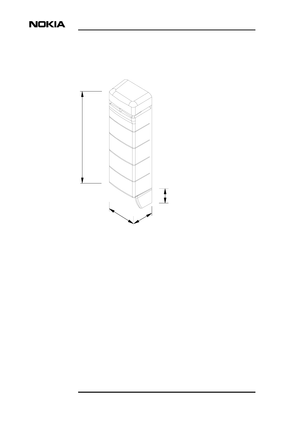
3.2.1 Nokia MetroSite BTS dimensions and weight
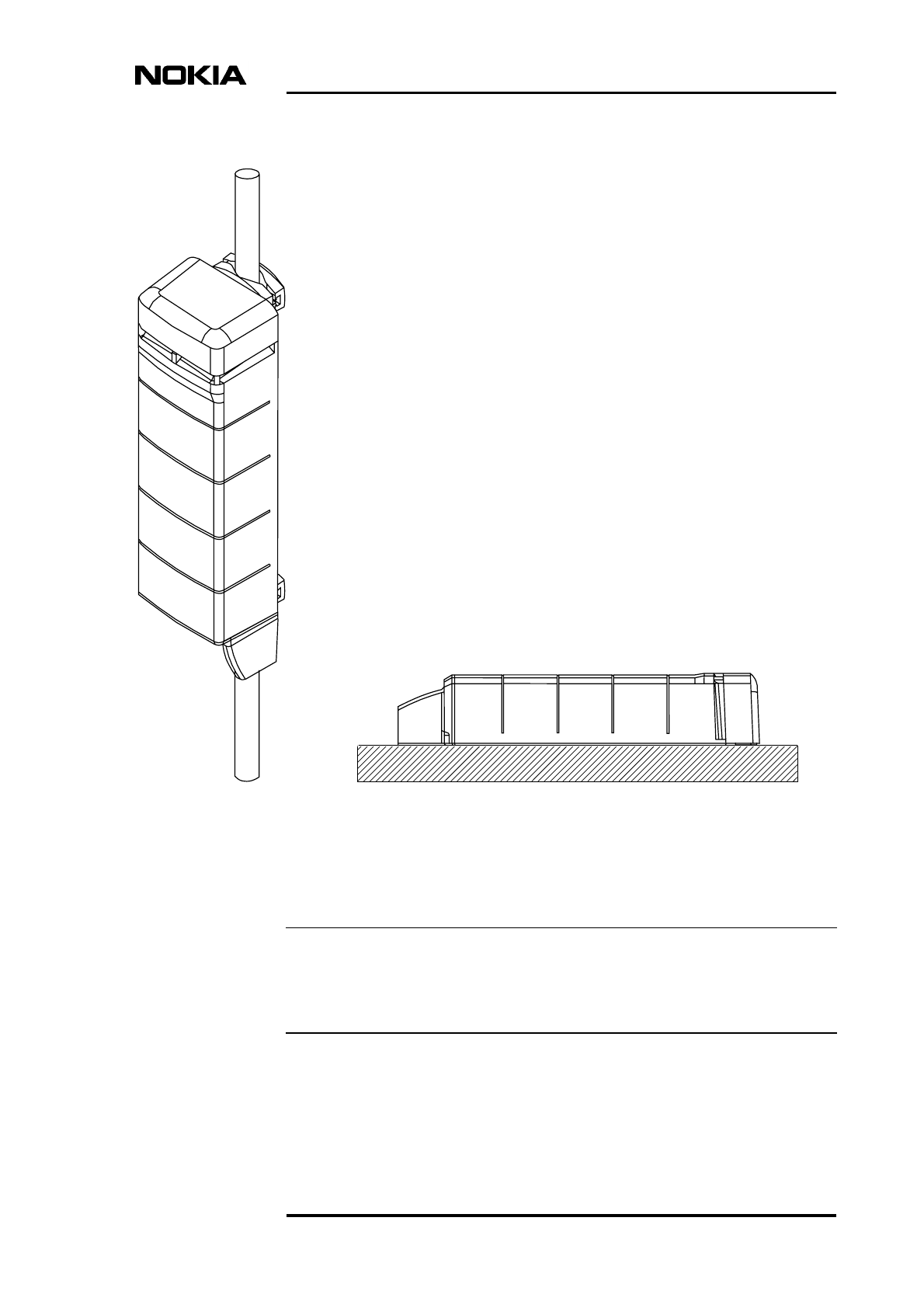
Figure 1 presents the dimensions of the Nokia MetroSite GSM BTS.
Figure 1. Dimensions of Nokia MetroSite BTS cabinet
The Nokia MetroSite GSM BTS with four TRXs weighs approximately 40 kg
(88.4 lb). The mounting rack weighs approximately 2 kg (4.4 lb). The dimensions
and weights of the plug-in units can be found in Nokia MetroSite GSM Base
Station: Product Description.
3.2.2 Clearances around BTS
The required clearances around the Nokia MetroSite GSM BTS are shown in
Figure 2.
310 mm 215 mm
114 mm
870 mm
(34.25 in)
(4.49 in)
(12.20 in) (8.46 in)
Installation requirements
DN9913471 © Nokia Networks Oy Internal Copy 19 (38)
Issue 1 en DRAFT 2 Draft
Figure 2. Clearances around Nokia MetroSite BTS
The packing cardboard provides a template for defining the clearances around the
BTS and for marking the drilling holes needed for wall mounting. Use the
template for defining how much space is required:
Top view
Front view
Min
50
(2.0)
260
(10.2)
245 (9.65)
310 (12.2)
100 (3.94)
480
(18.9)
300 (11.9)
260
(10.2)
260
(10.2)
235
(9.3)
100 (3.94) 100 (3.94)
235
(9.3)
235
(9.3)
300 (11.9) 300 (11.9)
N
O
TE: DIMEN
S
I
O
N
S
mm
(
inch
)
870mm (34,25 in)
1270mm (50 in)
DN9977591
Nokia MetroSite GSM Base Station, Requirements for Installation and Operation
20 (38) © Nokia Networks Oy Internal Copy DN9913471
Issue 1 en DRAFT 2 Draft
Note
• For removing units on the right-hand side of the BTS
• For removing the cover above the BTS
• For hanging the cover on the left-hand side of the BTS
• For cables and for cooling under the BTS
In order to hang the cover on the side of the cabinet during installation and
maintenance, a clearance of 250 mm (10 in) is required. This space can be
dispensed with, if the cover can be placed safely elsewhere (for example, on the
floor). In this case, only a clearance of 50 mm (2 in) is required.
Refer to wall mounting instructions in Nokia MetroSite GSM Base Station:
Installation for more information on how to use the template.
3.3 Mounting locations and positions
The Nokia MetroSite GSM BTS can be mounted on a wall or on a pole. Both
indoor and outdoor applications are possible. The Nokia MetroSite GSM BTS can
also be mounted horizontally in the position shown in Figure 3. Other horizontal
positions are not permitted.
The space in which the Nokia MetroSite GSM BTS is located must have proper
ventilation.
Installation requirements
DN9913471 © Nokia Networks Oy Internal Copy 21 (38)
Issue 1 en DRAFT 2 Draft
Note
Figure 3. Mounting of Nokia MetroSite BTS
If there is a risk that lumps of snow or pieces of ice can fall onto the BTS (from
the antenna or microwave radio pole, for example), an effectual roof must be
mounted to shield the BTS.
B) Horizontal mountingA) Vertical mounting
Nokia MetroSite GSM Base Station, Requirements for Installation and Operation
22 (38) © Nokia Networks Oy Internal Copy DN9913471
Issue 1 en DRAFT 2 Draft
3.4 Requirements for wall and pole installation
Qualified personnel must inspect the installation wall and/or pole before
mounting the BTS. Ensure that the installation wall or pole is strong enough to
bear the weight of the BTS (max. 40 kg / 88.4 lb) in any condition.
The optional pole mounting kit can be used when the installation pole diameter is
between 60 and 300 mm (2.36 and 11.81 in).
Anchor screws
The anchor screws are used for attaching the Nokia MetroSite GSM BTS to the
wall. These screws are not included in the delivery.
The anchor screws must be M6 size, stainless steel with the minimum breaking
strength (Rm) of 800 N/mm2. An appropriate counterpart for the anchor screw
(for example, an anchor plug) must be selected according to the screw and the
mounting base material. If the anchor screws are of other standard than the metric
standard, they must be selected so that they meet the requirement set to the metric
standard screws mentioned above.
Wind load
For pole mounting a pole must be selected which does not break off even in
stormy winds. Table 4 shows the load imposed on the pole (with a BTS attached
to it) in two wind velocities.
3.5 Grounding
To protect the Nokia MetroSite GSM BTS from damaging overvoltages through
antenna equipment, communication cables, or power supply lines, grounding
cabling must be planned and installed before the installation of the base station.
To avoid interference, it is recommended that large grounding systems be
designed case-specifically.
Table 4. Wind load
Wind velocity Load imposed on
the pole
40 m/s
89 mph
410 N
50 m/s
112 mph
640 N
Installation requirements
DN9913471 © Nokia Networks Oy Internal Copy 23 (38)
Issue 1 en DRAFT 2 Draft
Note
Note
A power plug with protective ground connection is not sufficient for Nokia
MetroSite BTS. Grounding must have a fixed, non-removable connection.
Regulations issued by local authorities/legislation must be followed when
planning the grounding of a BTS site!
In general, grounding is planned as presented in the following:
• The grounding cable is connected with screws or with a nut to the
grounding point of the Nokia MetroSite GSM BTS, depending on which of
the two grounding point alternatives is chosen. All Nokia MetroSite GSM
BTSs are equipped with two grounding point alternatives: a cable clamp
and a grounding stud. The selection between the two alternatives must be
done according to local regulations. When grounding stud is used, the
grounding cable must be fitted with an appropriate lug.
• The minimum cross-section of the copper (Cu) grounding conductor is 16
mm2 (5 AWG) in outdoor installations. In indoor installations, the
minimum cross-section of the copper grounding conductor is 2.5 mm2(12
AWG)
• The maximum cross-section of the copper grounding conductor is 35 mm2
(2 AWG)
• The maximum value of ground resistance is 10 Ω
• The ground cable must be connected to a main grounding busbar
• The routing of the ground cable must be as direct as possible. Unnecessary
loops should be avoided
• The external antenna feeders must also be grounded, if the antennas are
exposed to lightning
A grounding cable can be ordered from Nokia.
Nokia MetroSite GSM Base Station, Requirements for Installation and Operation
24 (38) © Nokia Networks Oy Internal Copy DN9913471
Issue 1 en DRAFT 2 Draft
WARNING
3.6 Mains power
The power switch on the power supply unit of the Nokia MetroSite GSM
BTS does not disconnect it from the power network (AC or DC), but leaves
it in a stand-by mode. The switch has two positions: ON and stand-by. A
separate main switch on the site is considered a disconnect device for safety
and service purposes.
Follow the national legislation when working with the power supply. The
Nokia MetroSite GSM BTS must be permanently wired to a disconnect
device (e.g. circuit breaker) in accordance with current local and national
wiring standards.
All ground connections must be secure and non-removable.
All power cabling must meet the requirements of the appropriate national
standard.
The Nokia MetroSite GSM BTS has three power supply options: 230 VAC, 110
VAC and 36/48/60 VDC. The permitted voltage fluctuation for the different
options is presented in Table 5.
It is recommended that the AC mains be protected with a lightning and transient
overvoltage protector (mains wire-in protector). This protection is not included in
the Nokia MetroSite GSM BTS.
3.6.1 Power consumption
The power consumption of the Nokia MetroSite GSM BTS is dependent on the
following factors:
Table 5. Permitted operating voltage fluctuation
Nominal operating
voltage
Permitted operating
voltage fluctuation
230 VAC ±20%
110 VAC ±20%
36/48/60 VDC ±20%
Installation requirements
DN9913471 © Nokia Networks Oy Internal Copy 25 (38)
Issue 1 en DRAFT 2 Draft
• BTS configuration
• Ambient temperature
• Direction of the temperature change
The power consumption is higher when the ambient temperature is decreasing
and the heating power of the BTS is increasing. When the ambient temperature is
rising, the heating power is reducing. Consequently, the power consumption of
the Nokia MetroSite GSM BTS in a given temperature varies according to the
direction of temperature change. Figure 4 presents the power consumption values
in different ambient temperature for three BTS configurations.
Figure 4. Power consumption of Nokia MetroSite BTS
o
C
Power / W
50
100
150
200
250
300
350
400
450
4 TRX + 2 FlexiHoppers
4 TRX
2 TRX
Ambient temperature rising
Ambient temperature falling
o
F
+32 +68 +122
+14
-40-58 -22 -4 +50 +104 +140+86
-50 -40 -30 -20 -10 0+10 +20 +30 +40 +50 +60
TAmb
Nokia MetroSite GSM Base Station, Requirements for Installation and Operation
26 (38) © Nokia Networks Oy Internal Copy DN9913471
Issue 1 en DRAFT 2 Draft
3.6.2 Acoustic sound power
The fan unit of the Nokia MetroSite GSM BTS generates acoustic noise. The
level of acoustic sound power is dependent on the following factors:
• Ambient temperature
• Rate of the temperature change
• Ouput power
The acoustic sound power level is higher when the ambient temperature is
changing rapidly. Refer to Figure 5 for the range of acoustic sound power level in
different ambient temperatures.
Figure 5. Range of acoustic sound power generated by Nokia MetroSite
GSM BTS
TAmb
Acoustic sound power
30
35
40
45
50
55
Fan off
-50 -40 -30 -20 -10
0
+10 +20 +30 +40 +50 +60
o
F
+32 +68
+122
+14
-40 -22
-4
+50
+104 +140
+86
o
C
-58
60
dB(A)
outdoor
indoor
Installation requirements
DN9913471 © Nokia Networks Oy Internal Copy 27 (38)
Issue 1 en DRAFT 2 Draft
Note
Note
Note
3.6.3 Connectors, cables and fuses for cable protection
Prefabricated mains power cables can be ordered from Nokia.
If you use the prefabricated mains power cable supplied by Nokia, make sure that
the power distribution box (mains power supply) is located no further than 10
metres from the BTS’s power supply unit.
Table 6 presents the requirements for power supply cables and the recommended
mains fuses.
In general, the fuses for cable protection have to be rated according to the national
electrical safety regulations.
The pin configurations for the different BTS power supply connector types can
be found in Nokia MetroSite GSM Base Station: Product Description.
Table 6. Connectors, cables and recommended fuses
Power
supply
type
Connector
type at the
end of cable
Cable
Recommended
fuse for cable
protection
AC supply
230 V
IEC 320
(female)
Multicore cable 3 x 0.75
to 1.5 mm2(181/2to 151/2
AWG)
10A for 1.5 mm2(151/2
AWG)
6A for 0.75 mm2(181/2
AWG)
AC supply
110 V
IEC 320
(female) with
notch
Multicore cable 3 x 1.5
mm2 (151/2 AWG)
10 A
DC supply
36/48/60 V
Anderson
Power Pole
Multicore cable 3 x 2.5
mm2 or 3 single wires 2.5
to 4.0 mm2 (13 to 11
AWG)
No recommendation,
refer to local
regulations
Nokia MetroSite GSM Base Station, Requirements for Installation and Operation
28 (38) © Nokia Networks Oy Internal Copy DN9913471
Issue 1 en DRAFT 2 Draft
Caution
3.7 Painting the BTS cover
If desired, the BTS cover can be painted to make it better blend into the
surrounding environment.
Nokia recommends that for painting the cover a primer-topcoat combination of
Beckers TD 130 primer (for priming) and Beckers TH 141 paint (for surface
painting) be used. Other paints suitable for polycarbonate surfaces may also be
used.
Do not use any paint that contains alkalis, esters, ketones, aromatic, chlorinated,
or fluorinated hydrocarbons, since these may damage the cover. Paint containing
these chemicals can only be used if approved by the manufacturer for painting
polycarbonate objects.
The selected paint must be UV and weather-resistant and suitable for
temperatures ranging from -40 °Cto+50°C (-40 °F to 122 °F). For environmental
conditions, refer to ETS 300 019-1-4:1992 class 4.1.
To paint the BTS cover:
1. Remove the BTS cover as instructed in Nokia MetroSite GSM BTS:
Maintenance.
2. Before painting, detach the cable cover and the cable cover support from
each other to prevent them from stucking to each other by paint and to
ensure that paint is applied evenly. The cover top can also be detached from
the cover by unscrewing the Torx T20 screws (see Figure 6).
Installation requirements
DN9913471 © Nokia Networks Oy Internal Copy 29 (38)
Issue 1 en DRAFT 2 Draft
Figure 6. Removing the cover top
3. Remove stains and dust from the surface of the cover with an alcoholic or
acidic wash, or wipe it clean with a piece of cloth moistened with water and
mild washing agent. Do not use washing agents that contain alkalis,
aromatic, chlorinated, or fluorinated hydrocarbons, esters or ketones.
4. Rinse with water to remove residuals of cleaning chemicals.
5. Dry the cover parts by blowing ionized air on them to remove electrostatic
charges and dust particles.
6. Place a support under the cover and the cover top so that you do not have
to touch the parts during painting.
7. Use a clamp or hook for holding the cable cover and the cable cover
support during painting. See Figure 7 for areas on which to place the clamp.
Nokia MetroSite GSM Base Station, Requirements for Installation and Operation
30 (38) © Nokia Networks Oy Internal Copy DN9913471
Issue 1 en DRAFT 2 Draft
Note
Note
Figure 7. Areas used for holding the cable cover parts during painting
8. Spray paint over the outside surface of the cover. Spraying should be done
at room temperature with relative air humidity of 50-65%.
The maximum thickness of the paint should not exceed 100 µm.
9. Dry the parts either in an oven or let the paint dry at room temperature
according to the paint manufacturer’s drying instructions.
The temperature of the drying oven must not exceed 90 °C (194 °F).
10. After the paint is dry, attach the cover top to the cover. Tighten the screws
to 1.6 Nm (1.18 ft-lb).
Cabinet interfaces and cables
DN9913471 © Nokia Networks Oy Internal Copy 31 (38)
Issue 1 en DRAFT 2 Draft
Note
4Cabinet interfaces and cables
This chapter describes the external interfaces and interconnecting cables
(excluding the grounding and power supply cables) for the Nokia MetroSite GSM
BTS. Pin configurations for the relevant connectors can be found in Nokia
MetroSite GSM Base Station: Product Description.
Antenna line cables, LMP cable, Abis cables and Flexbus cables can be ordered
from Nokia.
The MetroSite BTS interface connectors and cables are described in Tables 7 and
8.
Table 7. MetroSite BTS connectors
Interface
connector
Number of
connectors
Connector
type Cable type/diameter
Antenna
connector
1 for each TRX N-type 1/4” or 3/8” RF cable
External
Alarms and
Controls
1 (10 alarm
inputs, 4 control
outputs)
26-pin mini D
(female)
13-pair 28 AWG, 106 Ω
Flexible SCSI-2 Cable type
CL2/FT1
Extension
connectors
(not used)
2 50-pin mini D
(female)
N/A
Q1 interface 1 TQ 2-pair telecom cable, max. 6
mm
Local
Management
Port
1 BQ, RS- 232 (at
the BTS end)
D9 female (at
the PC end)
2-pair telecom cable. For
more information, refer to
Nokia MetroSite GSM Base
Station: Commissioning
.
Nokia MetroSite GSM Base Station, Requirements for Installation and Operation
32 (38) © Nokia Networks Oy Internal Copy DN9913471
Issue 1 en DRAFT 2 Draft
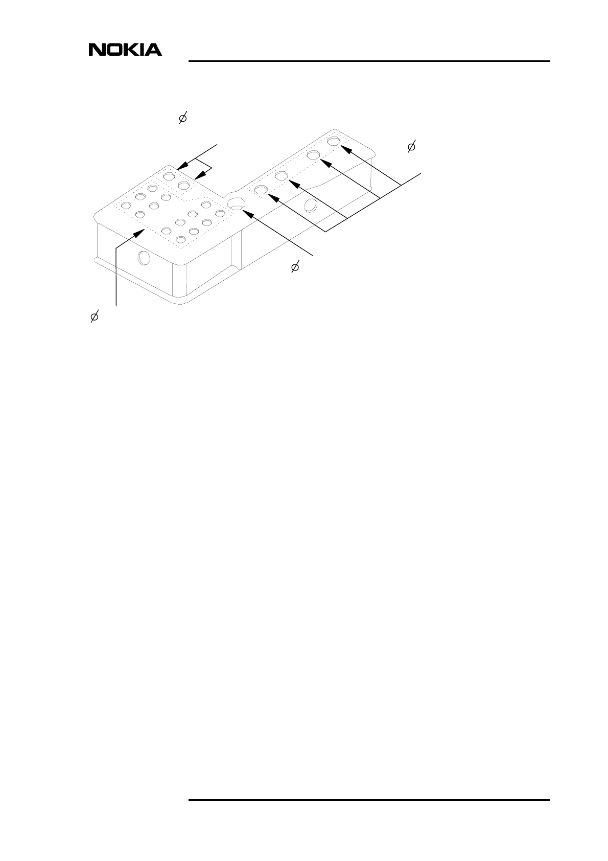
4.1 Cable entry block
The size of the cable entry holes must be considered when planning the cabling
of the Nokia MetroSite GSM BTS. The cable entry block is made of elastic
material. The holes can accommodate varying cable diameters as shown in Figure
8.
Table 8. Transmission connectors of Nokia MetroSite BTS
Transmission
unit type
Number of
connectors Connector type Cable
FC RRI 1 TNC 50 ΩFlexbus RG-223 (max
length 140 m),
Flexbus RG- 214 (max.
length 300 m)
For more information,
refer to
Nokia MetroSite
GSM Base Station:
Product Description
.
FC E1/T1 3 Two coaxial BT43
connectors (75 Ω)
one balanced TQ
connector (100/120
Ω)
Coaxial for 75 Ω
connector
twisted pair for 100/120 Ω
connector.
Max. allowed attenuation
for E1 20 dB; for T1 26 dB
FXC RRI 2 TNC 50 ΩCoaxial Flexbus RG-223
(max. length 140 m),
coaxial Flexbus RG-214
(max. length 300 m).
For more information,
refer to
Nokia MetroSite
GSM Base Station:
Product Description
.
FXC E1 75 Ω8 Coaxial BT43
connectors
Coaxial
Max. allowed attenuation
20 dB
FXC E1/T1 120/
100 Ω version
4 Balanced TQ
connectors
Twisted pair
Max. allowed attenuation
for E1 20 dB, for T1 26 dB
Cabinet interfaces and cables
DN9913471 © Nokia Networks Oy Internal Copy 33 (38)
Issue 1 en DRAFT 2 Draft
Figure 8. Cable entry block: cable diameters
4.5-7 (.18-.28), 14 pcs
7-10 (.28-.39), 2 pcs
10-15 (.39-.59), 1 pc
NOTE: DIMENSIONS mm (inch)
Extension cables
Power supply cable
Antenna feeders
- Grounding cable, 1 pc
- Transmission cables, max 8 pcs
- External alarms and controls
8-12.5 (.31-.49), 4 pcs

Nokia MetroSite GSM Base Station, Requirements for Installation and Operation
34 (38) © Nokia Networks Oy Internal Copy DN9913471
Issue 1 en DRAFT 2 Draft
Installation equipment
DN9913471 © Nokia Networks Oy Internal Copy 35 (38)
Issue 1 en DRAFT 2 Draft
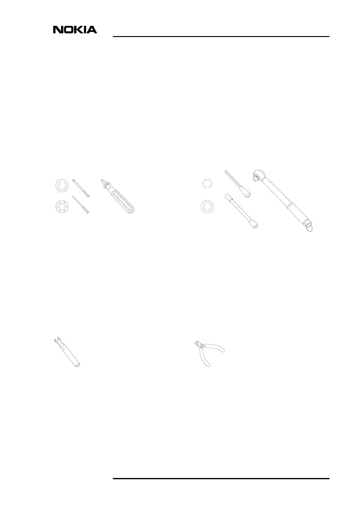
5Installation equipment
This section specifies the equipment that is recommended for the installation of
the Nokia MetroSite GSM BTS, but not included in the BTS delivery.
Figure 9. Recommended tools for installing the BTS
Side-cutting pliers
- for cutting the cable ties
Torque socket spanner/wrench
(5-20 Nm/3-14 ft-lb) with:
- 6 mm Allen bit
A) for bolts of pole bracket
version 1 (12 Nm/8.85 ft-lb)
B) with 80 mm extension for L-beam
offset screws (12 Nm/8.85 ft-lb)
- 8 mm hexagon socket with
min. 80 mm extension
A) for worm screw on pole bracket
version 2 (10 Nm/7.37 ft-lb)
B) for fixing the grounding nut
(5.5 Nm/4.06 ft-lb)
Torque key
- for diversity cables (1 Nm/.74 ft-lb)
Torque driver (0-6 Nm/0-5 ft-lb) with:
- T10 Torx bit with min. 60 mm shaft
for unit retaining screws
(1.5 Nm/1.11 ft-lb)
- 4 mm Allen bit with min. 60 mm shaft:
A) for BTS fixing screws
(5.5 Nm/4.06 ft-lb)
B) for fixing cable entry
block screws
C) for fixing grounding cable
(5.5 Nm/4.06 ft-lb)
Nokia MetroSite GSM Base Station, Requirements for Installation and Operation
36 (38) © Nokia Networks Oy Internal Copy DN9913471
Issue 1 en DRAFT 2 Draft
Note
Additional equipment includes:
• LMP cable for connecting the manager PC to the BTS
• Antistatic wrist strap
• Spirit level for checking the horizontal level of the BTS
• Tape measure
• Cable ties for routing the cables
• Crimping tool for assembling the power supply cable connector (AC and
DC)
A set of tools needed for assembling the cable connectors is available at Nokia.
• Cable stripper for assembling the power supply cable (AC and DC)
connector
• Screwdriver for assembling the AC cable connector
• Ladder (depending on circumstances on site)
• 10 mm spanner for removing the grounding bridge on the transmission unit
(optional)
• T20 Torx torque driver for removing and tightening the BTS cover top
retaining screws (optional)
• Centre punch for marking drilling hole locations in wall mounting
(optional)

DN9913471 © Nokia Networks Oy Internal Copy 37 (38)
Issue 1 en DRAFT 2 Draft
Index
A
acoustic noise 15,26
C
cable diameters 31,33
cable entry block 32
cable protection 27
cables
antenna feeders 32
extension 32
external alarms and controls 32
grounding 32
power supply 32
transmission 32
types 31
checking the site 17
clearances 18
connector types 31
D
diameters, cables 31,33
dimensions
BTS 18
E
electromagnetic compatibility (EMC) shielding 15
environmental conditions
operation 13
storage 9
transportation 11
equipment for installation 35
F
fuses 27
G
grounding 22
grounding cable 23
grounding conductor 23
grounding points 23
I
ingress protection 15
installation
requirements for 17
installation equipment 35
installation space 17
interface connectors 31
M
mains power 24
mounting
locations 20
positions 20
requirements for 22
O
operation
climatic conditions 13
international standard for 13
mechanical conditions 15
safety requirements for 15
P
packing cardboard 20
painting the BTS cover 28
power consumption 24
power supply options 24
R
requirements for installation 17
S
site survey 17
space requirements 17
stand-by mode 24
storage
climatic conditions 9
international standard for 9
mechanical conditions 10
T
tools 35
transportation
climatic conditions 11
international standard for 11
mechanical conditions 13
