Nokia Solutions and Networks MMDS-BASE1 Broadband Wireless Access Base Station User Manual Configuring Installing and Using Base Stations
Nokia Solutions and Networks Broadband Wireless Access Base Station Configuring Installing and Using Base Stations
Contents
- 1. Manual 1
- 2. Manual Revised
Manual 1

Configuring, Installing,
and Operating Base
Stations
MMDS Broadband Wireless Access System
Date: April 4, 2001
Part Number:104-0100-0001-A

Expedience is a trademark of NextNet Wireless.
©2000-2001 NextNet Wireless, Inc. All rights reserved.
NOTICE: This equipment has been tested with a 20 dB gain antenna and found to comply with the Radio Frequency
Radiation Exposure Limits detailed below. A minimum of 1-meter separation between the installation/operator
technician and the transmitting antenna should be maintained.
Radio Frequency Radiation Exposure Limits.
f = frequency in MHz
* = Plane-wave equivalent power density
NOTE 1 TO TABLE 1: Occupational/controlled limits apply in situations in which persons are exposed as a
consequence of their employment provided those persons are fully aware of the potential for exposure and can exercise
control over their exposure.
Limits for occupational/controlled exposure also apply in situations when an individual is transient through a location
where occupational/controlled limits apply provided he or she is made aware of the potential for exposure.
NOTE 2 TO TABLE 1: General population/uncontrolled exposures apply in situations in which the general public may
be exposed, or in which persons that are exposed as a consequence of their employment may not be fully aware of the
potential for exposure or can not exercise control over their exposure.
Note: This equipment has been tested and found to comply with the limits for a Class A digital device, pursuant to part
15 of the FCC rules. These limits are designed to provide reasonable protection against harmful interference when the
equipment is operated in a commercial environment. This equipment generates, uses, and can radiate radio-frequency
energy, and, if not installed and used in accordance with the installation manual, may cause harmful interference to radio
communications. Operation of this equipment in a residential area is likely to cause harmful interference, in which case
users will be required to correct the interference at their own expense.
THE SPECIFICATIONS AND INFORMATION REGARDING THE PRODUCTS IN THIS MANUAL ARE
SUBJECT TO CHANGE WITHOUT NOTICE. ALL STATEMENTS, INFORMATION, AND
RECOMMENDATIONS IN THIS MANUAL ARE BELIEVED TO BE ACCURATE BUT ARE PRESENTED
WITHOUT WARRENTY OF ANY KIND. USERS MUST TAKE FULL RESPONSIBILITY FOR THEIR
APPLICATION OF ANY PRODUCT.
TABLE 1. Limits for Maximum Permissible Exposure (MPE)
Frequency range
(MHz)
Electric field-
strength (V/m)
Magnetic field-
strength (A/m)
Power density
(mW/cm 2 )
Averaging time
(minutes)
(A) Limits for Occupational/Controlled Exposures
0.3-3.0 614 1.63 *(100) 6
3.0-30 1842/f 4.89/f *(900/f2)6
30-300 61.4 0.163 1.0 6
300-1500 — — f/300 6
1500-100,000 — — 5 6
(B) Limits for General Population/Uncontrolled Exposure
0.3-1.34 614 1.63 *(100) 30
1.34-30 824/f 2.19/f *(180/f2)30
30-300 27.5 0.073 .2 30
300-1500 — — f/1500 30
1500-100,000 — — 1.0 30
NOTWITHSTANDING ANY OTHER WARRANTY HEREIN, ALL DOCUMENT FILES AND SOFTWARE
ARE PROVIDED "AS IS" WITH ALL FAULTS. NEXTNET WIRELESS DISCLAIMS ALL WARRANTIES,
EXPRESSED OR IMPLIED, INCLUDING, WITHOUT LIMITATION, THOSE OF MERCHANTABILITY,
FITNESS FOR A PARTICULAR PURPOSE AND NONINFRINGEMENT OR ARISING FOM A COUSRE OF
DEALING, USAGE, OR TRADE PRACTICE.
IN NO EVENT SHALL NEXTNET WIRELESS OR ITS SUPPLIERS BE LIABLE FOR ANY INDIRECT,
SPECIAL, CONSEQUENTIAL, OR INCIDENTAL DAMAGES, INCLUDING, WITHOUT LIMITATION, LOST
PROFITS OR LOSS OF DAMAGE TO DATA ARISING OUT OF THE USE OR INABILITY TO USE THIS
MANUAL, EVEN IF NEXTNET WIRELESS HAS BEEN ADVISED OF THE POSSIBILITY OF SUCH
DAMAGES.

i
C
HAPTER
0
C
ONTENTS
Preface About this guide
Preface Overview ............................................................................... ix
About this guide ................................................................................ ix
Chapters in this guide ........................................................................................... x
Additional documentation ................................................................. xi
How to obtain additional documentation ........................................................ xi
Typographical conventions this guide uses ..................................... xii
Where to go for more help ............................................................... xiii
Technical support............................................................................................... xiii
Documentation additions and corrections..................................................... xiii
Chapter 1 Introduction to base station
installations
Chapter overview ..............................................................................1-1
System overview ................................................................................1-1
Base station overview ....................................................................................... 1-2
Installation overview .........................................................................1-3
Planning the installation ...................................................................1-4
Choosing an installation location .................................................................... 1-4
Assessing service provider equipment needs ................................................ 1-6
Planning for the antennas and antenna installation tips .............................. 1-6
Chapter 2 Configuring base stations
Chapter overview ............................................................................. 2-7
Before you begin .............................................................................. 2-7
Using Term or Telnet to help configure base stations ................... 2-8
Connecting through Telnet ............................................................................. 2-8
Connecting through terminal emulation ....................................................... 2-9
ii Configuring, Installing, and Using Base Stations
Terminal emulation connection settings ................................................. 2-9
Setting base station configuration parameters ................................ 2-9
set airlink channel number ............................................................................. 2-10
set airlink downlink power ............................................................................. 2-11
set downlink bias ............................................................................................ 2-11
set airlink state .................................................................................................2-12
Chapter 3 Installing base stations
Chapter overview ............................................................................3-13
Before you begin .............................................................................3-13
Cell wiring .......................................................................................3-14
Base station connectors ..................................................................3-15
Ethernet (data) and power connector .......................................................... 3-15
Ethernet/power connecting cable .........................................................3-16
TVS module connectors ................................................................................ 3-18
Base station to TVS connector .............................................................. 3-18
Power supply cable and ISP Ethernet network connector ................ 3-18
GPS connectors ............................................................................................... 3-19
GPS connecting cable/Inter-base station connecting cables ............ 3-20
Serial interface connector ............................................................................... 3-21
Serial interface connecting cable ............................................................ 3-21
Antenna connector ......................................................................................... 3-21
Mounting the base station ..............................................................3-21
Mounting the base station to a wall .............................................................. 3-22
Mounting the base station to a tower .......................................................... 3-23
Connecting the antenna to the base station .................................. 3-23
Antenna connection tips ................................................................................ 3-23
Connecting the antenna to the base station ................................................ 3-24
Connecting the GPS equipment to a base station ........................ 3-24
GPS equipment mounting tips ..................................................................... 3-24
Connecting the GPS unit to the base station ............................................. 3-25
Connecting to the backbone network ........................................... 3-26
Powering base stations .................................................................. 3-26
Powering tips ................................................................................................... 3-26
iii
Powering the base station .............................................................................. 3-27
Verifying system operation ............................................................ 3-27
Appendix A Parts list
Appendix overview ........................................................................A-29
Appendix B MMDS frequency range
Appendix overview ........................................................................B-31

iv Configuring, Installing, and Using Base Stations
v
C
HAPTER
0
F
IGURES
Preface About this guide
Chapter 1 Introduction to base station
installations
Figure 1.1 Base station mounted on tower with antenna
connection .................................................................... 1-2
Chapter 2 Configuring base stations
Chapter 3 Installing base stations
Figure 3.1 Cell wiring diagram ................................................... 3-14
Figure 3.2 Base station connectors ........................................... 3-15
Figure 3.3 Ethernet (data) and power connector ................... 3-16
Figure 3.4 TVS module connector: Base station connector . 3-18
Figure 3.5 TVS module connector: Power/Ethernet
connector ....................................................................3-19
Figure 3.6 GPS connector .......................................................... 3-19
Figure 3.7 Serial interface connector ........................................ 3-21
Figure 3.8 Base station mounting template ............................. 3-22
Appendix A Parts list
Appendix B MMDS frequency range

vi Configuring, Installing, and Using Base Stations
vii
C
HAPTER
0
T
ABLES
Preface About this guide
Chapter 1 Introduction to base station
installations
Table 1.1 Base station physical characteristics ................................ 1-3
Table 1.2 Advantages/disadvantages of location choices ............. 1-5
Chapter 2 Configuring base stations
Table 2.1 Base station transmit power level .................................. 2-11
Table 2.2 Data transfer rate associated with set downlink
bias command .................................................................. 2-12
Chapter 3 Installing base stations
Table 3.1 RJ-45 base station cable choices .................................... 3-16
Table 3.2 RJ-45 cable pins ............................................................... 3-16
Table 3.3 Function of wires in cable 597-6013-0xxx ................... 3-17
Appendix AParts list
Table A.1 Parts list ............................................................................ A-29
Appendix BMMDS frequency range

viii Configuring, Installing, and Using Base Stations

ix
PREFACE
C
HAPTER
0
A
BOUT
THIS
GUIDE
Preface Overview
Thank you for choosing the Expedience system from NextNet Wireless. This
guide describes how to configure and install the system’s base station
component.
This preface describes:
• Audience for this guide
• Additional documentation
• Typographical conventions used in this guide
• Where to go for more help
About this guide
This guide describes how to configure and install the system’s base station.
This guide is intended for network and system administrators who must
install, configure, and manage base stations. This guide provides detailed
configuration and installation instructions.

xConfiguring, Installing, and Operating Base Stations
It is assumed readers of this guide are familiar with:
• Basic networking concepts
• Layer 2 (link layer) of OSI model
• Cell structure engineering
Chapters in this guide
Table i describes the chapters and appendices in this guide.
Table i
Chapters and appendices in the guide
Chapter Description
Preface Provides an overview of the guide, related
documentation, the guide’s intended audience,
typographical conventions, and methods for
obtaining technical support.
Chapter 1 Introduction to
base station installations
Provides an overview of the Expedience system
and of the system’s base station component. It
provides an installation overview and describes
things you need to consider before installing
base stations.
Chapter 2 Configuring
base stations
Describes how to configure base stations,
including how to use Telnet or Term to set up a
base station before deploying it and mounting it to
a tower or building. The chapter also describes
how to configure base stations after you have
deployed them, for example, to maintain the
system and optimize system performance.
Chapter 3 Installing base
stations
Explains how to install a base station at a cell
site. Also describes the components used to
mount the base station on a building or tower.
Appendix A Parts list Lists part numbers of system components that
are related to base station installations

xi
Additional documentation
If you cannot find the information you need in this guide, you may want to refer to
the documents described in Table ii.
How to obtain additional documentation
These documents are available in hard copy format. You can also download
documents from the NextNet Wireless web site. You need a user name and
password to do so. To download the documentation:
1Use your Internet browser to go to:
www.nextnetwireless.com
2On the home page, click the Products link.
3On the page that appears, click the product name for which you want
documentation.
4Click the document link.
5A list of documentation appears. To access the documentation file, click
the title of the file you want to review.
Table ii
Additional documentation
Guide Description
Getting Started with the
Expedience System
Provides an overview of the Expedience
system, its components, its network
architecture, and options for selecting a
deployment scheme for the system in your
backbone network.
Using the NextNet Operating
System (NNOS)
Describes the operating system commands
you can use to configure and control the
Expedience system, as well as the
interfaces (command line and Web) that
you can use to issue NNOS commands to
base stations and CPEs.
Installing and using the CPE Intended for use by your subscribers, this
guide describes how to install a CPE at a
subscriber site. The CPE is completely
installable by your subscribers.
White paper TBD

xii Configuring, Installing, and Operating Base Stations
Typographical conventions this guide uses
Table iii describes the typographical conventions that this guide uses.
Table iii
Typographical conventions
Convention Meaning
Bold face If you are using a graphical user
interface (GUI), bold face indicates a
button, menu option, icon, and so on,
that you manipulate directly.
If you are using a command line
interface, bold face indicates
commands and keywords.
Bold face can also indicate information
that you must enter.
Italic face Arguments for which you supply
values are in italic face.
Courier (mono-spaced) font
A command you type in, exactly as it
appears, at a command line.
[ ... ] Arguments that appear inside square
brackets [ ], are optional.
Also, when the guide shows a system
prompt, the default system prompt
appears inside square brackets.
{..} | {..} Required keywords are grouped in
braces and separated by vertical bars.
Note Notes contain helpful suggestions for
the reader.
<...> Non-printing characters, such as
passwords, appear in angle brackets.
Caution Cautions contain information about
which the reader must exercise care.
Warning Warnings contain information about
how readers might do something
resulting in harm to themselves or in
damage to equipment or data.

xiii
Where to go for more help
This section describes how to obtain support for your NextNet Wireless product.
It also describes how to provide comments on the product documentation.
Technical support
NextNet Wireless is committed to providing our customers with high quality
technical support. Table iv describes how to contact technical support.
Documentation additions and corrections
If you find documentation errors, or want to see additional information not
presented in this guide, please contact our documentation group at the
following e-mail address:
techdocs@nextnetwireless.com
Table iv
Contacting technical support
Contact Description
Phone 800.000.0000 (United States)
1.952.###.#### (Internationally)
E-mail support@nextnetwireless.com
Web site www.nextnetwireless.com

xiv Configuring, Installing, and Operating Base Stations

1-1
CHAPTER
1
C
HAPTER
1
I
NTRODUCTION
TO
BASE
STATION
INSTALLATIONS
Chapter overview
This chapter provides an overview of the Expedience system and of the system’s
base station component. It provides an installation overview. The chapter also
describes things you need to consider before installing base stations.
System overview
NextNet Wireless designed the Expedience system to give small office, home
office (SOHO), and residential subscribers high speed, wireless access to network
communication systems, such as the Internet.
The Expedience system is an end-to-end broadband wireless access system for
multichannel multipoint distribution service (MMDS) frequencies (2.5 - 2.686
GHz). The system is a local loop, wireless alternative that offers a last mile solution
for packet data and voice.
The Expedience system consists of two equipment components: customer premise
equipment (CPE) and base stations. You install base stations in sectors, within
cells.
The system does not have a line-of-sight (LOS) requirement between the base
station and the CPEs. The air link between base stations and CPEs functions as an
Ethernet bridge carrying IP/ARP packets. Time division duplex (TDD) and
1-2 Configuring, Installing, and Using Base Stations
cellular deployment offer you flexibility in adjusting downlink versus uplink
airtime.
For more system overview information, refer to the guide “Getting Started with
the Expedience System.”
Base station overview
The base station maintains contact with CPEs at your subscribers’ sites. The base
station integrates the transceiver and modem into one device.
From a transmitting tower, the base station can cover can approximate radius of 1
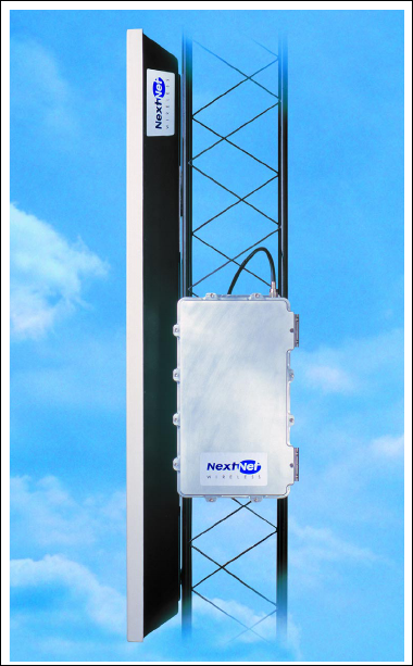
to 3 miles, with a 5 mile maximum. Figure 1.1 shows a base station.
Figure 1.1
Base station mounted on tower with antenna connection

1-3
Table 1.1 describes base station physical characteristics.
Installation overview
This section provides a high-level overview of the base station installation process.
Other sections in this guide then explain these installation tasks in detail.
The tasks you perform to deploy base stations are:
1Choose an appropriate location for the base station installation. For more
information, refer to the section, “Choosing an installation location” on
page 1-4 in this chapter.
2Plan for system components that you need to supply to complete the network.
For more information, refer to the section, “Assessing service provider
equipment needs” on page 1-6 in this chapter.
3Configure the base stations, before deploying them in the field. For more
information, refer to the chapter, in this guide.
4Mount the base station at the site you selected. For more information, refer to
the section, “Mounting the base station” on page 3-21 in this guide.
5Connect the antenna to the base station, as described in the section,
“Connecting the antenna to the base station” on page 3-23.
6Mount the GPS device and connect it to the base station. One GPS device can
service the multiple base stations at a cell site. For more information, refer to
the section, “Connecting the GPS equipment to a base station” on page 3-24 in
this guide.
7Connect the base station to the transcient voltage suppressor (TVS) module,
then connect the TVS module to your network switch.
The TVS module splits the connection: one connection goes to a switch that
connects to your network, and the other goes to a power supply. For more
Table 1.1
Base station physical characteristics
Characteristic Description
Dimensions 18.34 in. x 11.25 in. x 5.25in.
Weight 40 pounds
Temperature range -30 C to 50 C
Heat load If housed in environmentally
controlled enclosure, heat load is 490
BTU/hour

1-4 Configuring, Installing, and Using Base Stations
information, refer to the section, “Connecting to the backbone network” on
page 3-26 in this guide.
8Power the base stations by connecting the TVS module to the power supply.
For more information, refer to the section, “Powering base stations” on
page 3-26 in this guide.
9Before leaving the site, verify that the system is operating. For more
information, refer to the section, “Verifying system operation” on page 3-27 in
this guide.
Planning the installation
This section describes issues you need to consider before you install the base
stations, including:
• Location considerations
• Service provider equipment components
Choosing an installation location
The base station’s location at a site depends on many factors, including the site’s
physical environment, the coverage pattern you want to achieve, and the ease of

1-5
maintenance you require. Table 1.2 describes some of the locations you might want
to consider.
Note: Regardless of the location you choose, plan to provide a weatherproof
housing unit for the network switch, the power supply, and the TVS
equipment.
Table 1.2
Advantages/disadvantages of location choices
Location Advantages Disadvantages
On tower, at
antennas
Installing at the antennas offers
cost savings, due to the fact that
you can use a shorter coaxial
cable to connect the base stations
to your cells. This also offers the
ability to transmit at higher
power levels, since there is lower
signal loss in shorter cables.
When you install base stations
near the top of the tower,
installation and maintenance are
more difficult.
At base of tower Placing the base stations at the
base of a tower offers simpler
installation and maintenance
than a base station installed on
the tower, at the antennas.
Base station installation and
maintenance are simpler than
other options;
If you install at the base of the
tower, you need to run a coaxial
cable from the base stations to
the cells. This cable must be of
sufficient size to reduce signal loss,
which may increase costs.
Installation still requires you to
install the antennas and coaxial
cable.
On rooftop You can use a shorter coaxial
cable to connect base stations to
cells. As such, you can probably
operate at higher power levels,
and still stay within signal loss
criteria.
Rooftop access is usually
available, making installation and
maintenance easier. Also, a
housing unit for the backbone
network switch, power supplies,
and other equipment is typically
available.
You need to obtain permission
to use a rooftop, and comply
with building codes.
1-6 Configuring, Installing, and Using Base Stations
Assessing service provider equipment needs
The Expedience system supplies the base stations, the CPEs, and an Ethernet
cable that connects the CPE to the subscriber’s PC or LAN network interface card
(NIC).
Before you install and deploy the base station, ensure you have made provisions
for the following components:
• Power and data connection between the base station and your network
• Domain name server (DNS), DHCP server, SNMP server, and authentication,
authorization, and accounting (AAA) server
• Global position system (GPS) for proper TDD functions. You must use the
GPS supplied with the Expedience system.
• Antenna system for transmitting and receiving signals for the base stations.
• Weatherproof housing for the backbone network switch, power supplies, UPS,
and lightning protection.
• Co-axial cable to connect the base station to the panel antenna.
• Tower or building structure on which to mount cell site equipment.
Planning for the antennas and antenna installation tips
The type of antenna you choose depends on the cell type and pattern you want to
use. Make sure:
• The antenna is a high-gain antenna, at least 20dBi, or higher.
• The installation of the antenna complies with the vendor’s installation
directions, and that it meets building codes.
After you have installed an antenna, you need to connect it to a mounted base
station. For instructions on connecting the antenna to a base station, refer to the
section, “Connecting the antenna to the base station” on page 3-23.

2-7
CHAPTER
2
C
HAPTER
2
C
ONFIGURING
BASE
STATIONS
Chapter overview
This chapter describes how to configure base stations. It describes:
• How to configure base stations before you deploy them.
• How to configure base stations after you have deployed them, for example, to
maintain the system and optimize system performance
Before you begin
To configure base stations before you deploy them on towers or buildings, you
must first supply power to the base station, and connect the base station to a PC or
laptop using the serial cable/serial connection. To perform these tasks:
1Plug one end of the base station-to-TVS cable into the base station. Plug the
other end into the TVS module. Then, plug the TVS module into a power
source.
2Use the serial interface cable to connect your management station to the base
station to enable communication between the devices.
3On your computer, start a terminal emulation or Telnet session with the base
station you want to configure.
4Configure the base station using the parameters described in the section
“Setting base station configuration parameters” on page 2-9 in this guide.

2-8 Configuring, Installing, and Using Base Stations
Using Term or Telnet to help configure base
stations
The base station supports the following methods of configuration and
management:
• SNMP server
• Web server
• Telnet, terminal emulation over a serial line
To configure the device initially, you will most likely use a serial connection and a
terminal emulation session.
• Telnet allows access to the base station through remote access over the
Ethernet network using the base station’s IP address.
• Terminal emulation allows access through a direct RS-232 connection from a
personal computer to the base station.
Before you mount a base station, it is recommended that you use the terminal
emulation connection to assign a name to the base station.
Connecting through Telnet
To use Telnet, the base station’s IP address must be known, or referenced through
the base station’s name stored on a domain name server (DNS).
Before installing a base station, it is recommended that you use the terminal
emulation serial connection (described in the section that follows) to assign a name
to the base station, for example “Cell2Sector4.” Assigning the base station a name
makes it easier for you to identify devices in the network.
When you implement the base station in your network, the base station acquires an
IP address from a DHCP server on your network. After receiving the IP address,
the base station supplies the now associated name and assigned IP address to
DNS.
Note: During initial set up of your equipment, you can use a DHCP server on your
network to assign the base station an IP address, or you can set the address
manually. For more information, refer to the guide “Using the NextNet
Operating System (NNOS).”

2-9
Connecting through terminal emulation
The terminal emulation connection is a physical RS-232 cable connection, between
the base station and a PC. Once the connection is made, you can use a program
such as Hyperterminal under the Windows operating system to configure and
communicate with the station.
Before installing a base station, it is recommended that you assign the base station
a name, using terminal emulation and the “set name” and “set location”
commands in NNOS. Assigning a name makes it easier for you to identify the
device in the network. Also, depending on IP lease time, an IP address can change
each time you power on the base station or reset it.
Terminal emulation connection settings
To set up a terminal emulation connection, use these settings:
• 19.2 baud
•8 data bits
• No parity
• 1 stop bit
• no flow control
Setting base station configuration parameters
This section describes configuration parameters you must set for proper base
station functioning.
You can use Telnet, terminal emulation, the NNOS web interface, or an SNMP
session to configure the parameters on the base station.
When setting up the base station, you must:
1Set the following parameters, in the order that follows:
•set airlink channel number
•set airlink power
•set airlink downlink bias
•set airlink state
2After setting the parameters, use the write command to write the settings into
the flash, non-volatile memory.

2-10 Configuring, Installing, and Using Base Stations
3For your changes to take effect, perform one of the following:
•Re-boot the base station
--OR--
•Power down the base station, and then re-power it.
For more information about these configuration parameters, as well as a full list of
configuration parameters, refer to the guide “Using the NextNet Operating
System.”
set airlink channel number
Set this configuration parameter to the channel on which you want to run the
airlink. The channel range for ITFS and MMDS frequencies is 1-31. For an
illustration of the channels, refer to Appendix B.
Example:
set airlink channel number 15

2-11
set airlink downlink power
This parameter specifies the base station’s transmit power level. Specify a power
value from 0 to 31.
The maximum system power level is 10, which specifies +33 dB at 2 watts. The
other power levels are measured in 1 dB steps from the maximum.
Example:
set airlink downlink power 10
set downlink bias
This parameter specifies the portion of airtime (slots) available for use on the
downlink relative to the airtime for the uplink. There are always 6 slots available for
the uplink.
The higher the bias, the more bandwidth is available for the downlink, due to more
time allocated to the downlink.
Example:
set airlink downlink bias 9
Table 2.1
Base station transmit power level
Power value Power level
10 +33 dBm or 2.0 watts
.
.
13 +30 dBm 1.0 watt
.
.
16 +27 dBm 500 milliwatts
.
.
23 +20 dBm 100 milliwatts
.
.
31 +12 dBm 15.8 milliwatts

2-12 Configuring, Installing, and Using Base Stations
You must specify the same downlink bias for all base stations in a cell. Likewise, all
base stations within your system, regardless of the cell they are in, must have the
same downlink bias.
set airlink state
This parameter enables the airlink.
After you specify the set airlink channel number, set airlink downlink power, and
set downlink bias parameters, you must set the airlink state to enabled, for your
changes to take effect.
Example:
set airlink state enabled
You can take the base station off the air by disabling the airlink.
Table 2.2
Data transfer rate associated with set downlink bias command
Bias
number
variable
Downlink slots
available*
Downlink rate
(bps) Uplink rate (bps)
06 downlink slots 1,364,496 1,249,920
191,747,872 1,028,160
214 2,157,216 794,880
317 2,325,024 699,840
420 2,456,440 624,960
523 2,562,112 564,480
629 2,718,464 472,320
733 2,798,976 426,240
837 2,868,480 388,800
941 2,924,416 357,120
10 54 3,055,248 282,240
11 61 3,103,232 253,440
12 67 3,140,208 233,280
13 73 3,170,400 216,000
14 80 3,198,840 198,720
15 90 3,236,400 178,560
*Note: There are always 6 slots available for the uplink.

3-13
CHAPTER
3
C
HAPTER
3
I
NSTALLING
BASE
STATIONS
Chapter overview
This chapter describes how to install base stations. It describes:
• Components used to mount the base station on a building or tower.
• Connecting the base station to the cell and to cell-site components
Before you begin
Before you install a base station on a roof top or tower:
• It is recommended that you assign a name to the base station. For more
information refer to Chapter 2, “Configuring base stations‚” in this guide.
• It is also a good idea to configure the base station.
3-14 Configuring, Installing, and Using Base Stations
Cell wiring
Figure 3.1 shows how a cell, base stations, and ancillary equipment are wired
together.
Figure 3.1
Cell wiring diagram
1 2 6
Panel
Antenna*
Coax jumper*
Coax - main
feed*
Coax jumper*
GPS Unit
GPS
Interface
Cable
TVS
Module
Backbone swtich* P ower s upply*
UPS*
AC power cord*
DC power cable*
In-line or
panel fuse*
Base station
*Not provided as component of
standard NextNet Wireless base
station product
GPS inter-base
station cable
E thernet/power
cable
Load
Termination
Optional S erial
C onnection and
Laptop Compute
r
Backbone
connection cable*
E thernet cable*
3-15
Base station connectors
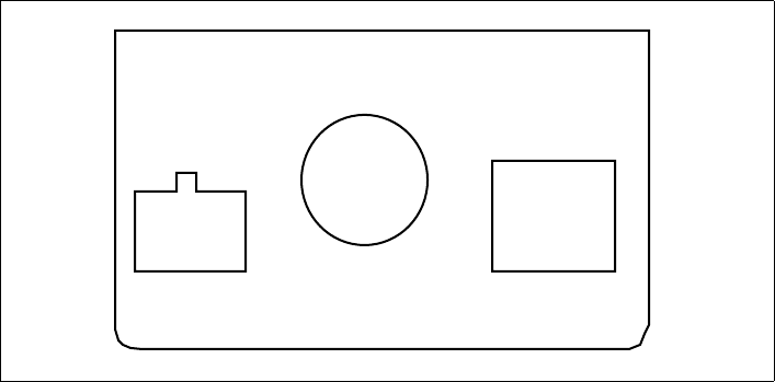
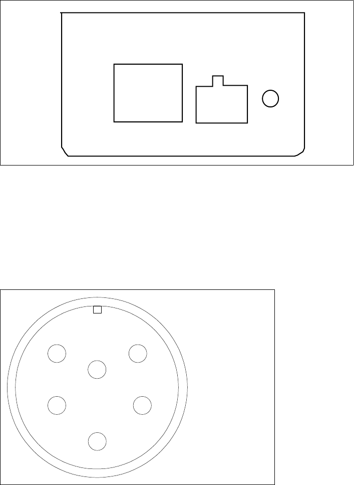
Figure 3.2 shows the connectors that the base station supports.
Ethernet (data) and power connector
The Ethernet and power connector supplies data and DC power to the base
station. The circular connector has 8 pins:
• Ethernet transmit uses 2 pins.
• Ethernet receive uses 2 pins.
• Power ground uses 2 pins
• Power V+ uses 2 pins.
Figure 3.2
Base station connectors
Base Station
Antenna Connector
J4 - Serial Connector
J3 - GPS Connector
J2 - GPS Connector
J1 - Ethernet/Power
Connector
3-16 Configuring, Installing, and Using Base Stations
Figure 3.3 shows the pins of the Ethernet and power connector on the base
station, looking at the connector on the base station.
Ethernet/power connecting cable
Depending on your needs, you can order any of the following cables to connect
the base station to the TVS module.
Table 3.2 describes the pins of the RJ-45 cable (the Ethernet/power cable) that
connects the base station to the TVS device.
Figure 3.3
Ethernet (data) and power connector
Table 3.1
RJ-45 base station cable choices
Cable part number Length (feet)
597-6013-0010 10
597-6013-0025 25
597-6013-0050 50
597-6013-0100 100
597-6013-0200 200
Table 3.2
RJ-45 cable pins
Pin Connection
1Tx+
2Tx-
3Rx+
28
1
6
7
4
5 3
1 - EN TD+
2 - EN TD-
3 - EN RD+
4 - EN RD-
5 - Power V+
6 - Power V+
7 - Power V-
8 - Power V-

3-17
Table 3.3 describes the color and function of the wires in cable 597-6013-0xxx.
4Rx-
5 +48 VDC
6 +48 VDC
7 -48 VDC
8 -48 VDC
Table 3.3
Function of wires in cable 597-6013-0xxx
Wire color Wire function
White/orange Tx+ Ethernet
Orange Tx- Ethernet
White/green Rx+ Ethernet
Green Rx- Ethernet
Red +48 VDC
Red/white +48 VDC
Black -48 VDC
Black/white -48 VDC
Table 3.2
RJ-45 cable pins
Pin Connection
3-18 Configuring, Installing, and Using Base Stations
TVS module connectors
The TVS module has connectors on both its right and left sides.
Base station to TVS connector
The base station connector supplies power and an Ethernet connection to the base
station. Connect cable 597-6013-0xxx to this side of the TVS module.
Note: Use the AUX +48 VDC and AUX ETHERNET connections only if you
need to cut off the circular connector from the power/Ethernet cable (597-
6013-0xxx). For example, if you need to route the cable through a wall at
your installation site, you will not use the circular connector. Instead, you will
split the cable and put a 6-pin, RJ-11 connector on some wires, and a power
connector on others. Then, you will plug the appropriate connector from the
split cable into the corresponding connector in the TVS module. Table 3.3
describes the wires in the cable.
Power supply cable and ISP Ethernet network
connector
The other side of the module has a connector for both an Ethernet cable coming
from your ISP network and for the +48 VDC power coming from a power supply.
Note: To ensure your base station is properly protected from possible lightning
strikes, ensure you plug the power cable coming from your power supply
into this connector in the TVS module. If you plug the power cable into the
Figure 3.4
TVS module connector: Base station connector
POWER / ETHERNET
AUX
+48 VDC
Base
Connection AUX
ETHERNET
+ -
3-19
base station connector side, the base station will power up, but you will NOT
be properly protected against possible lightning strikes.
GPS connectors
The base station supports two GPS connectors: one connector is used to supply
the GPS signal, either by a direct connection to the GPS device, or by a daisy chain
connection to another base station in the cell. The other GPS connector is used to
make a daisy-chain connection from the current base station to the next base
station.
Figure 3.5
TVS module connector: Power/Ethernet connector
ISP
Ethernet +48 VDC
Power
+ -
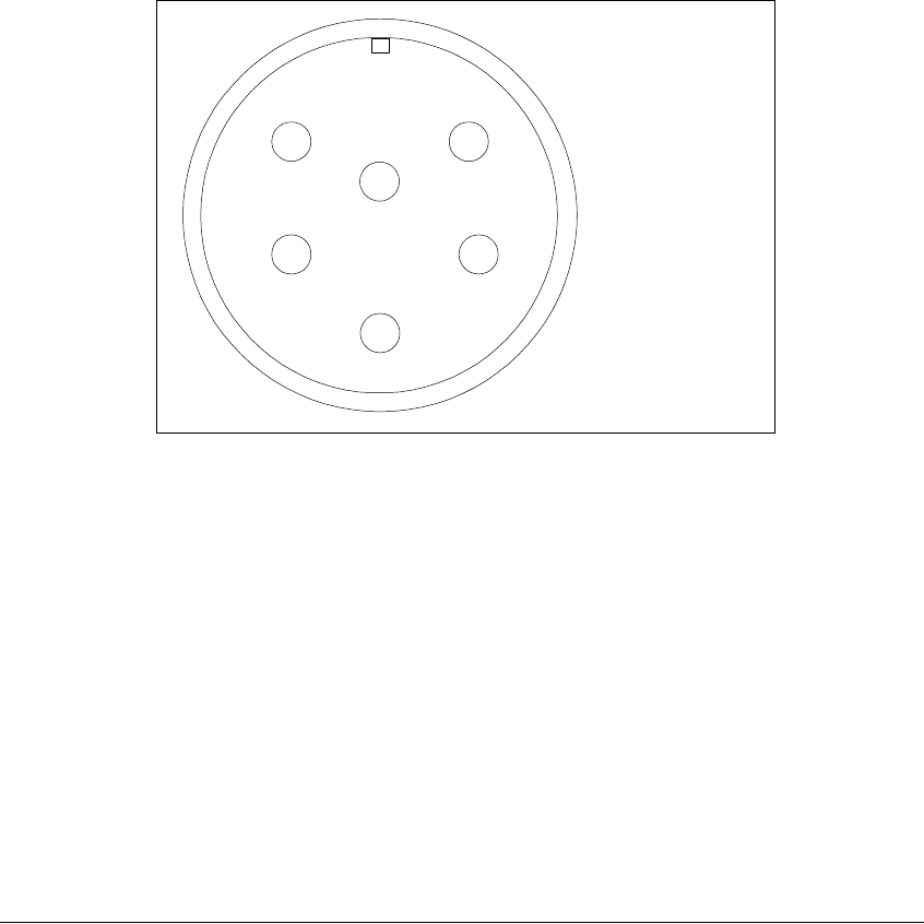
Figure 3.6
GPS connector
51
3
2 4
1 - 1PPS+
2 - 1PPS-
3 - 422Data+
4 - 422Data-
5 - 18V+
6 - Ground
6
3-20 Configuring, Installing, and Using Base Stations
An RS-422 line feeds 1PPS+ and 1PPS- with the time synchronization pulse from
the GPS equipment to the base station.
An RS-422 line also feeds 422Data+ and 422Data-, to allow data communication
from the GPS device to the base station. Currently, this is one-way
communication, with the GPS device giving the base station time information.
The 18V+ and ground pin supply power to the GPS device from the base station.
The GPS device uses 18 volts DC at 150 milliamperes.
GPS connecting cable/Inter-base station
connecting cables
You need one GPS device per cell. You then directly connect one base station
within that cell to the GPS device. Next, the other base stations are connected to
each other, using a daisy chain wiring scheme, so that all base stations in the cell
can receive a GPS signal.
You can choose the length of the cable that connects the base station to the GPS
receiver.
• The cable that comes standard in the base station site installation kit is 100 ft
(part number 597-6011-0100).
• If desired, you can use a shorter cable to connect the base station to the GPS
receiver. This alternate cable is 25 ft (part number 597-6011-0025).
You can also choose the length of the daisy-chain cable that connects one base
station to another base station.
• The standard cable shipped in the base station installation kit is 3 ft (part
number 597-6012-0003).
• If desired, you can use a longer cable to connect one base station to another.
This cable is 10 ft (part number 597-6012-0010)
If you need to remove a base station for service, you can use the longer, 10 ft. cable
to jumper the GPS cables together, and continue cell operation.
The last base station in the daisy chain requires a load termination to be connected
to the GPS connection. This base terminator plug is 100 ohm (part number 515-
6005-0001).
3-21
Serial interface connector
For base station configuration, the serial interface connector lets you directly
connect the base station to a PC or laptop. The six-pin connector is an RS-232
cable (10 ft), physical interface.
Note: “nu” indicates that the pin is not used.
Serial interface connecting cable
Cable 597-6014-0010 has a female, circular connector on one end, and a DB-9
female connector on the other end. Plug the DB-9 end of the cable into your PC or
laptop. Plug the other end of the cable into the serial interface connector.
Antenna connector
The antenna connector is a type N female connector. It has a built-in, internal 1/4
wave stub lightning protector. Connect the base station to the antenna using a
coaxial cable. Connect the proper lightning ground wiring to the antenna lightning
protector.
Mounting the base station
You can mount the base station to any surface. To mount the base station to a
wall, you need to use the supplied mounting brackets. If you are installing the base
Figure 3.7
Serial interface connector
51
3
2 4
1 - nu
2 - TxD
3 - RxD
4 - TxD
5 - nu
6 - Ground
6

3-22 Configuring, Installing, and Using Base Stations
station on a tower, you need to use mounting plates, which you need to acquire
from another equipment supplier.
Mounting the base station to a wall
To mount the base station to a wall:
1Find a surface suited to base station installation.
aPlan to install the base station vertically, so the antenna connector is at the
top (facing skyward), and the other circular connectors are at the bottom
(facing the ground).
bMake sure the area above and below the location where you want to install
the base station has a good distance for clearance. This clearance allows for
proper air circulation and heat flow from the heat sink fins on the back of the
base station. The clearance also allows for the coaxial cable and the other
cable connections.
2Drill mounting holes into the surface, according to the dimensions shown in
Figure 3.8.
3To attach the base station to a wall, use the mounting brackets. Install them on
the base station first, then attach the brackets to the wall. To attach the brackets
Figure 3.8
Base station mounting template
0.375" dia (4)
4.000"
18.000"

3-23
to the base station, use 5/16 inch x 18 inch UNC thread bolts and a lock
washer. Use your own bolts to then attach the bracket to the surface.
Mounting the base station to a tower
Use the tower connecting plate to attach the base station to a tower. To mount the
base station on a tower:
1Find a place on the tower that is suited to base station installation.
aPlan to install the base station vertically, so the antenna connector is at the
top (facing skyward), and the other circular connectors are at the bottom
(facing the ground).
bMake sure the area above and below the location where you want to install
the base station has a good distance for clearance. This clearance allows for
proper air circulation and heat flow from the heat sink fins on the back of the
base station and for cable connections.
2If you are installing the base station to a tower, you must use mounting plates.
Attach the plates to the base station, then attach the mounting plates to the
tower according to the directions from the plate manufacturer.
Connecting the antenna to the base station
This section provides tips you can use to connect the antenna to the base station. It
also provides step-by-step instructions for connecting the components to each
other.
Antenna connection tips
Use the following tips when connecting the base station to the antenna:
• You connect the antenna to the base station using a coaxial cable. The size of
the cable depends on the distance between the base station and the antenna.
•The greater the distance, the larger your coaxial cable needs to be, in order to
maintain low signal loss.
•It is recommended that you keep signal loss to a minimum. At a maximum,
the signal loss should be no more than 2 to 3 dB, including all coaxial cable
and connectors.
• Use short coaxial jumpers from the base station to the main coaxial line, and
from the main coaxial line to the antenna. It is recommended you use 1/2 inch

3-24 Configuring, Installing, and Using Base Stations
flexible line, of the shortest length possible, while still allowing the flexibility to
make a good connection.
• The base station contains an antenna connector with a 1/4 inch wave stub
lightning protector. You do not need to place an external lightning protector in
the coaxial cable.
Connecting the antenna to the base station
To attach the antenna to the base station:
1Mount the antenna according to the manufacturer’s instructions.
2Connect one end of a short coaxial jumper to the antenna. Connect the other
jumper end to the main coaxial cable.
3On the base station’s antenna connector, connect one end of a short coaxial
jumper. Connect the other jumper end to the main coaxial cable coming from
the antenna.
4Make sure the coaxial line is properly grounded.
5Properly seal the co-axial connections with weatherproof components, tape and
wrap.
Connecting the GPS equipment to a base station
The GPS equipment provides a time synchronization signal to the base station.
This signal is needed to ascertain the proper timing for time division duplexing
(TDD).
The equipment — supplied by NextNet and manufactured by Trimble Navigation
Limited — is a smart antenna in a sealed, shielded, self-contained unit that houses
a GPS receiver, GPS antenna, and interface circuitry. A lightning protector is also
supplied.
When powered, the GPS provides accurate time, with a time pulse of one pulse per
second, synchronized to Universal Time, Coordinated (UTC) within 150
nanoseconds.
GPS equipment mounting tips
You must use the supplied Trimble GPS system to supply a time synchronization
signal to the base stations in a cell. You cannot use a GPS from another
manufacturer.
3-25
The GPS and lightning protector do not ship with mounting accessories. You can
obtain these accessories from many suppliers around the world, especially
distributors of marine products.
Follow these tips when mounting the GPS:
• Mount the GPS unit on a threaded pipe or pole.
• The GPS mounting socket accepts a 1.0000 x 14 straight thread. It is
recommended that the pole/pipe you use be 1.000 inch.
• Secure the pipe or pole to the building or other support structure.
• You must install lightning protection equipment. It is recommended that the
lightning protector be installed at the smart antenna end of the time source
interface cable. You must then directly connect the protection ground wire to a
properly grounded equipment chassis or antenna mast.
• Ensure at least half of the sky is clearly visible to the unit.
• Expose the unit to the southern portion of the sky. GPS satellites move
generally from the southwest to the northeast.
Connecting the GPS unit to the base station
One GPS unit can support numerous base stations in the same cell.
Use the GPS-to-base station cable to attach the GPS unit to one of the base
stations in the cell.
To connect the cable to the GPS unit and to the base station (both of which have
already been installed and mounted):
1Connect the cable’s molded, circular female connector to the GPS unit.
2Install the lightning protection equipment. It is recommended that the lightning
protector be installed at the smart antenna end of the time source interface
cable. You must then directly connect the protection ground wire to a properly
grounded equipment chassis or antenna mast.
3After connecting the cable to the GPS unit, run the cable to the base station.
Plug the cable’s other end into the base station’s GPS connector.
4Secure the cable that you just ran to an appropriate support structure. Coil and
tie any excess cable.
5The GPS unit receives its power from the base station. The base station supplies
power to the GPS device, which uses 18 volts DC at 150 milliamperes.
6So that the remaining base stations in the cell can receive a GPS signal, connect
a base station adjacent to the base station you just connected to the GPS unit.

3-26 Configuring, Installing, and Using Base Stations
Continue to use the daisy chain wiring scheme to connect the remaining base
stations, until all of the base stations within the cell are connected to each other.
On the last base station in the daisy chain, connect the load termination on the
open GPS connection.
Connecting to the backbone network
The base station connects to a TVS module. You then connect the TVS module to
your network. Typically, base stations connect to a level 2 switch at the cell site,
using a 10BaseT connection. The switch controls the base station data traffic to
and from the backbone network.
Connect the switch to the backhaul network using the appropriate cabling.
Powering base stations
This section describes tips for powering base stations, as well as the component
connection sequence you need to use to properly power base stations.
Powering tips
• It is recommended that you use a redundant power supply for base stations.
• Each base station requires 48 volts DC at 3.0 amps maximum
• Depending on the type of equipment you own, supply power to the Ethernet
switch and backbone network equipment.
• It is recommended that you use an uninterruptable power supply (UPS).
Tips for sizing the UPS include:
•Size the voltage and amperage of the power supply according to the number
of base stations at your cell site.
•Size the UPS according to the efficiency of the DC power supplies and
power requirements of the other ancillary equipment, such as the Ethernet
switch and backbone network equipment.
•Consider the time you want to allow the system to operate on the UPS.

3-27
Powering the base station
The base station does not have a power switch. Rather, it receives its power when
the UPS, power supply, and TVS module are connected to the base station
through the Ethernet/power cable.
To connect the base station to a power supply, connect these components in the
order that follows:
1Connect the base station to the antenna.
2Connect the GPS to a base station, and use a daisy chain wiring scheme to
connect the other base stations.
3Connect the base station to the TVS module using the Ethernet/power cable of
the desired length.
4Use an Ethernet cable to connect the TVS module to the network. Use a
standard DC power cable to connect the TVS module to the power supply.
5Connect the power supply to the UPS.
6Connect the UPS to an AC power supply.
Verifying system operation
Before you leave the cell site, make sure the system is operational. To do so:
1TBD
2TBD
3TBD
3-28 Configuring, Installing, and Using Base Stations

A-29
APPENDIX
A
C
HAPTER
0
P
ARTS
LIST
Appendix overview
This appendix provides you with part numbers for the base station and for the
system components which support the base station.
Table A.1
Parts list
Component Part number
Base station 123-0100-1000
Base station mounting bracket 123-0100-0130
TVS module 123-0100-0125
“Configuring, Installing, and
Operating Base Stations” manual
104-0100-0001-A
Base station site installation kit,
which includes:
123-0100-0135
GPS unit 450-0010-2000
GPS lightning protector 450-0010-2001
Base station terminator plug
(100 ohm)
515-6005-0001
Base-to-base daisy chain
cables (5 cables, 3 ft. each)
597-6012-0003
Base to GPS receiver cable,
100 ft.
597-6011-0100
Serial interface cable, for base
station programming, 10 ft.
597-6014-0010

A-30 Configuring, Installing, and Operating Base Stations
Base station power/Ethernet
cable. Depending on your needs,
the following lengths are
available:
Base station power/Ethernet
cable, 10 ft.
597-6013-0010
Base station power/Ethernet
cable, 25 ft.
597-6013-0025
Base station power/Ethernet
cable, 100 ft.
597-6013-0100
Base station power/Ethernet
cable, 200 ft.
597-6013-0200
Base station site power supply kit,
which includes:
123-0100-0140
3 power supply modules 420-0100-0500
19 inch rack mounting chassis 420-0100-0501
Cable alternatives
Base station to GPS receiver,
25 ft.
597-6011-0025
Base station to GPS receiver,
100 ft.
597-6011-0100
Base-to-base daisy chain
cable, 3 ft.
597-6012-0003
Base-to-base daisy chain
cable, 10 ft.
597-6012-0010
Table A.1
Parts list
Component Part number

B-31
APPENDIX
B
C
HAPTER
0
MMDS
FREQUENCY
RANGE
Appendix overview
This appendix provides reference information about the MMDS frequency range.
MMDS stands for multichannel multipoint distribution service and is a system of
transmitting signals through microwave. MMDS represents frequencies in the 2.5
to 2.686 GHz band.
Although initially used to transmit video signals, MMDS has gone through
regulatory changes which allow licensees of the frequency range to engage in fixed,
two-way digital transmissions. The MMDS frequencies are ideally suited for
broadband delivery of data, voice, and Internet services.
Note that the MMDS band shares its range with the instructional television fixed
service (ITFS) band. ITFS makes up the A, B, C, D and G blocks. Each block
contains 4 channels. Blocks A through D occupy the contiguous space from 2500-
2596 MHz and the G block occupies space from 2644 to 2680 MHz, alternating
every other channel with the H block.
Although the Federal Communication Commission (FCC) did not auction licenses
for the ITFS frequencies, operators often lease the ITFS frequencies. These leases
are allowed as long as the operator transmits up to 40 hours of educational
programming per week. Sometimes, MMDS is referred to as wireless cable.
B-32 Configuring, Installing, and Operating Base Stations
Channel
2690
A1
B1 B2 B3 B4 D1 D2 D3 D4 F1 F2 F3 F4 H1 H2 H3
ITFS MMDS ITFS & MMDS
2500 2524 2548 2572 2596 2620 2644 2668
A2 A3 A4 C1 C2 C3 C4 E1 E2 E3 E4 G1 G2 G3 G4
1 2 3 4 5 6 7 8 9 10111213141516171819202122232425262728293031
Frequency
(MHz)
Index-33
A
AAA server equipment, 1-6
Airlink
enabling, 2-12
Ancilliary equipment
housing requirements, 1-6
Antenna
coaxial cable, 3-21
connector, 3-21
gain recommended, 1-6
installation tips, 3-23
lightning protection, 3-21
planning installation, 1-6
type used to transmit MMDS
channels, B-31
B
Backbone network
connecting to, 3-26
bandwidth
increasing on the downlink, 2-11
Base station
connectors, 3-15
daisy chaining within cell, 3-26
mounting, 3-21
naming, 2-8
power, 3-26
transmit power level, 2-11
C
Cable
coaxial cable, 3-21
Ethernet/power, 3-16
GPS inter-base station cable, 3-20
GPS interface cable, 3-20
serial interface, 3-21
Cell
wiring, 3-14
Channels
in MMDS frequencies, B-31
Coaxial cable, 3-21
jumpers recommended, 3-24
maximum signal loss allowed, 3-23
configuration parameters
setting before deploying base
station, 2-9
Connector
data, 3-15
Ethernet, 3-15
GPS, 3-19
power, 3-15
serial interface, 3-21
Connectors
supported by base station, 3-15
D
Daisy chain cable See GPS Inter-base
station cable
Daisy-chaining base stations, 3-26
DHCP server equipment, 1-6
DNS equipment, 1-6
Documentation
finding additional, preface-xi
E
Equipment
provided by service providers, 1-6
Ethernet/power cable, 3-16
Expedience system
obtaining technical support
for, preface-xiii
overview of, 1-1
F
Frequency range, 1-1
G
GPS
components of, 3-24
I
NDEX
Index-34 Configuring, Installing, and Operating Base Stations
connecting to base station, 3-25
connector, 3-19
daisy-chained base stations, 3-26
exposure requirements, 3-25
interface cable, 3-20
mounting pole and socket, 3-25
powering, 3-25
TDD impact, 1-6
time pulse generated, 3-24
GPS Inter-base station cable, 3-20
I
Inter-base station cable, 3-20
L
Lightning protection, 1-5, 1-6, 3-24, A-
29
antenna, 3-21
LOS requirement elimination, 1-1
M
MMDS frequency range
channels, B-31
Mounting
brackets, 3-21
template, 3-22
S
Serial interface
cable, 3-21
connector, 3-21
set airlink channel number, 2-10
set airlink downlink power, 2-11
set airlink state, 2-12
set downlink bias, 2-11
SNMP server equipment, 1-6
Subscribers
typical of the Expedience system, 1-1
T
Technical support, preface-xiii
Telnet access to base station, 2-8
Term connection
settings, 2-9
Terminal emulation
access to base station, 2-9
connection settings, 2-9
TVS module, 1-3, 1-4
Typographical conventions
overview, preface-xii
U
UPS
sizing considerations, 3-26
W
Wiring cells, 3-14