Nokia Solutions and Networks MMDS-CPE6 Non-Line of Site Wireless Data Link User Manual InstallExternalOSU
Nokia Solutions and Networks Non-Line of Site Wireless Data Link InstallExternalOSU
Contents
- 1. Manual
- 2. Manual statements
Manual

i
Installing and using the
Expedience Outdoor Subscriber
Unit (OSU)
Broadband Wireless Access System
This document is intended for use by professional equipment installers. Subscribers of the
high speed Internet service should not attempt to install the OSU.
Part Number:104-0009-0001-03
ii
Expedience and LinkMonitor are trademarks of NextNet Wireless, Inc.
Other brand and product names may be registered trademarks or trademarks of their respective holders.
Part number: 104-0009-0001-03
©2002-2003 NextNet Wireless, Inc. All rights reserved.
THE SPECIFICATIONS AND INFORMATION REGARDING THE PRODUCTS IN THIS GUIDE ARE SUBJECT TO CHANGE WITHOUT NOTICE. ALL
STATEMENTS, INFORMATION, AND RECOMMENDATIONS IN THIS GUIDE ARE BELIEVED TO BE ACCURATE BUT ARE PRESENTED WITHOUT
WARRANTY OF ANY KIND. USERS MUST TAKE FULL RESPONSIBILITY FOR THEIR APPLICATION OF ANY PRODUCT.
FOR WARRANTY INFORMATION ON THE EXPEDIENCE OSU, CONTACT THE INTERNET SERVICE PROVIDER THAT SUPPLIED THE OSU.
NOTWITHSTANDING ANY OTHER WARRANTY HEREIN, ALL DOCUMENT FILES AND SOFTWARE THAT ARE PROVIDED ON THE EXPEDIENCE
BROADBAND WIRELESS ACCESS MODEM CD-ROM ARE PROVIDED “AS IS” WITH ALL FAULTS. NEXTNET WIRELESS DISCLAIMS ALL WARRANTIES,
EXPRESSED OR IMPLIED, INCLUDING, WITHOUT LIMITATION, THOSE OF MERCHANTABILITY, FITNESS FOR A PARTICULAR PURPOSE AND
NONINFRINGEMENT OR ARISING FROM A COURSE OF DEALING, USAGE, OR TRADE PRACTICE.
IN NO EVENT SHALL NEXTNET WIRELESS OR ITS SUPPLIERS BE LIABLE FOR ANY INDIRECT, SPECIAL, CONSEQUENTIAL, OR INCIDENTAL
DAMAGES, INCLUDING, WITHOUT LIMITATION, LOST PROFITS OR LOSS OF DAMAGE TO DATA ARISING OUT OF THE USE OR INABILITY TO USE
THIS GUIDE, EVEN IF NEXTNET WIRELESS HAS BEEN ADVISED OF THE POSSIBILITY OF SUCH DAMAGES.
iii
CONTENTS
Welcome ..............................................................................................1
Before you begin ..................................................................................1
Additional material required for installation .....................................................1
Pre-installation planning ......................................................................................2
Connecting the OSU to a computer ................................................... 3
Installation overview .............................................................................................3
Cabling overview ...................................................................................................4
Installing the OSU .............................................................................. 5
Selecting an installation location for the OSU ..................................................5
Installation overview .............................................................................................5
Attach the mounting bracket to the outside of the building ..........................6
Setting the OSU inside the mounting bracket ..................................................8
Partially tightening adjustment screws to hold OSU in place ........................8
Running cables through building’s wall ...........................................10
Attaching the NIM box to the outside of building ........................... 10
Plugging cables into NIM box .......................................................... 11
Connecting ground wires .................................................................. 12
Plugging in power cord and RJ-45 cord ............................................13
(Optional) Finding the strongest service provider signal ................. 13
Installing the LinkMonitor program ................................................................13
Using the software-assisted method to find the strongest signal ................14
Using the sound (auditory) method to find the strongest signal .................15
Setting up the computer to receive an IP address ............................15
Configuring IP address assignment for routers ................................17
Connecting to the Internet ................................................................17
Refreshing the OSU’s connection .....................................................17
Windows users: Refreshing the connection ....................................................17
Non-Windows users: Refreshing the connection ..........................................17
Connecting the OSU to a network .................................................... 17
FCC information ................................................................................ 19
iv Installing and using the Expedience OSU

1
Welcome
This document describes how to install and use the Expedience outdoor subscriber unit
(OSU) to obtain wireless high-speed Internet access. Subscribers can connect the OSU to a
computer or to a small office/home office (SOHO) local area network (LAN) through a hub,
switch, or router.
This document is intended for use by professional equipment installers. Subscribers of the
high-speed Internet service should not attempt to install the OSU. For questions about OSU
operation or installation, subscribers should contact the ISP that supplied the OSU device.
Before you begin
This section describes items the installer or subscriber must purchase before the OSU is
installed. This section also describes items you need to have available and things to consider
before beginning the OSU installation.
Additional material required for installation
• The subscriber’s computer must be equipped with an Ethernet network interface card
(NIC). The NIC is not provided with the OSU, but subscribers can purchase a NIC at
most computer and electronics stores.
• An RJ-45 Ethernet cable. This cable must be an outdoor rated, TIA/EIA category 5
Ethernet cable. The length of this cable depends on where you plan to install the Network
Interface Manager (NIM) box on the building and where the computer (or hub) is placed
inside the building.
• Ground wire of sufficient length to run between the OSU and a ground rod. Also, you
need to obtain ground wire to run between the NIM box and the ground rod.
• It is recommended that the ground wire be an 8 AWG, solid aluminum or copper wire.
• It is recommended that the ground rod used be 8 feet (2.5 m) copper. Note that most
buildings have an existing ground rod outside, at the main power connection site. If
desired, you can install a rod into the ground outside the building.
• OSU to NIM box communication cable. Four lengths of cable are available. Select the
cable length appropriate to the OSU installation location. Table 1 lists the cable lengths
you can order and use.
• Anti-seize compound to be applied to the stainless steel screws that hold the OSU to the
mounting bracket.
• If you mount the OSU or NIM box on a brick or masonry surface, lead screw anchors are
required.
Table 1 OSU communication cables
Cable Part number
25 feet (7.5 m) 597-6020-0025
50 feet (15 m) 597-6020-0050
75 feet (22.5 m) 597-6020-0075
100 feet (30 m) 597-6020-0100

2Installing and using the Expedience OSU
Pre-installation planning
• Find an appropriate location on the outside of the building to mount OSU.
• To provide Internet service, the OSU communicates with a base station on the service
provider’s communications tower. The service provider must provide you with
information about the nearest communications tower. For example, if the tower nearest
to the building is north of the building, you will install the OSU on the north side of the
building.
• Mount the OSU on a high location on the building, such as under the eaves.
• Find an appropriate location on the outside of the building to mount the NIM box.
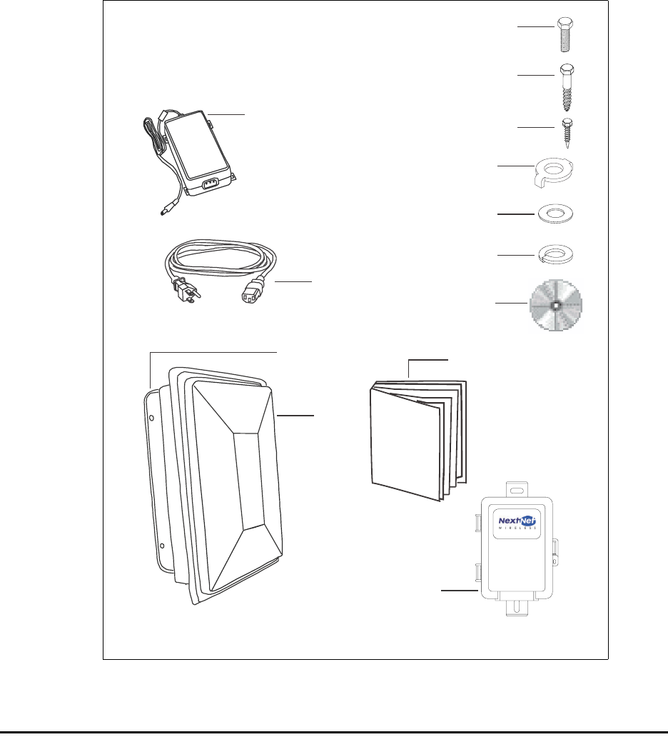
• Locate the components shipped with the OSU device. Table 2 lists these components.
Table 2 OSU package components
Component Part number Quantity
OSU device (vertical) 900-0055-1000 1
—OR—
OSU device (horizontal) 900-0055-2000 1
Mounting bracket 350-0009-0010 1
1/4 X 2" lag bolt, hex HD, grade 2 Galv. 594-9907-1464 4
1/4-20X.875 bolt, hex HD, SS 594-9909-1428 2
Self-drilling hex head 10 X 1.5 594-2909-1048 2
1/4 split lock washer, SS 596-3003-1416 3
1/4 flat washer, SS 596-3004-1420 7
Double tab washer 596-3099-1416 1
External OSU network interface box 123-0009-0055 1
Power supply (home to NIM) 420-0010-1010 1
Power cord 597-5120-0107 1
Wire tie 593-0005-0032 1
OSU Installation Guide 104-0009-0001 1
Installation software CD-ROM 110-0002-0001 1
3
Figure 3 illustrates the OSU package contents. Components are not to scale.
Connecting the OSU to a computer
This section describes how to connect the OSU to a computer.
If the OSU is to be connected to a network device (such as a router or switch), refer to the
section “Connecting the OSU to a network” on page 17, in this guide.
Installation overview
The installation consists of the following major tasks, each of which is explained in greater
detail in the sections that follow:
1Attach the OSU to the outside of the building.
2Run the power cable and the RJ-45 Ethernet cable through a hole drilled through the
building’s wall.
Figure 3 OSU package contents
Network interface box
Software CD-ROM
Power supply
O
S
U
I
n
s
t
a
l
l
OSU Installation Guide
OSU
Mounting bracket
Double tab washer (1)
Flat washer (7)
Split lock washer (3)
Power cable
Lag bolt (4)
Hex screw (2)
Self-drilling hex screw (2)
4Installing and using the Expedience OSU
3Mount the NIM box to the outside of the building.
4Connect the cables into the NIM box.
5Connect the ground wires.
6Connect the power cord to standard household power. Connect the RJ-45 Ethernet cable.
7Adjust the OSU to obtain the strongest service provider signal.
8Ensure that the computer is set up to automatically obtain an IP address.
9Connect to the Internet.
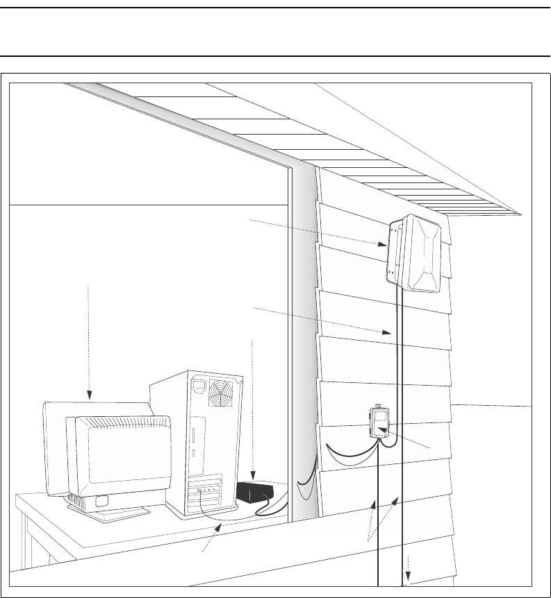
Cabling overview
Figure 4 illustrates the routing of the ground wires, the RJ-45 Ethernet cable, the power cord,
and the OSU communication cable.
Note: The ground wire, RJ-45 cable, anti-seize compound for the hex screws, and computer
NIC are not supplied with the system.
Figure 4 Connecting cables overview
Building’s roof
Building’s wall
OSU bracket mounted to
building's exterior
NIM box
to grounding rod
Power supply
Ethernet cable (not supplied)
Subscriber’s computer
Ground wire
OSU communication cable
mounted to
building’s exterior
(not supplied)
(not supplied)

5
Installing the OSU
This section describes how to find an appropriate installation location for the OSU and how
to install the OSU on the building.
Selecting an installation location for the OSU
It is recommended that you determine the optimum installation location for the OSU before
physically mounting the OSU and NIM box to the building.
To do so, use a residential subscriber unit (RSU). The RSU can detect where a signal from the
service provider can be received at the installation site.
Most often if you mount the OSU on the side of the building facing the service provider's
base station, the OSU can detect adequate signal in order to provide high-speed Internet
access. However, unless there is an obvious line of sight to the correct base station, the
correct orientation of the OSU is often not apparent. There also may be practical reasons why
you cannot mount the OSU on the side the building that faces the base station.
To use the RSU to determine where you might be able to install the OSU on the building,
point the back of the RSU in various directions around the installation site. The back of the
RSU is the side without logos.
At each direction you point the RSU, note the number of blinking lights on top of the RSU.
The stronger the signal that the RSU can detect, the more lights blink on and off.
After determining where signal can be detected around the building, you can then choose a
corresponding OSU installation location on the building. As you attach the OSU to the
building, make sure to point it in the same direction that the RSU was pointed when the RSU
detected a signal.
Note: When detecting signal at the site, you must use an RSU that has the same vertical or
horizontal polarization as the OSU to be installed.
For further instructions on how to use the RSU to detect service provider signal, refer to the
Expedience Broadband Wireless Modem User Manual for the RSU. You can find an
electronic version of this document on the software CD supplied with the OSU.
For further information about additional procedures you can use to further optimize the
OSU installation, refer to the section “(Optional) Finding the strongest service provider
signal” on page 13 in this guide.
Installation overview
To install the OSU:
1Attach the mounting bracket to the outside of the building.
2Set the OSU inside the mounting bracket.
3Tighten the lower mounting bolt to hold the OSU in place.
The following sections describe these steps in greater detail.

6Installing and using the Expedience OSU
Attach the mounting bracket to the outside of the building
1Where possible, install the OSU on the side of the building that has the greatest exposure
to the communications tower of the service provider.
The service provider can provide information about tower locations that can provide the
OSU with greatest signal exposure.
2Install the mounting bracket to the building. The bracket (like the OSU) must be installed
vertically.
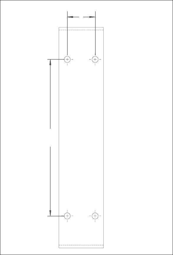
• Drill the two top holes 1.25 inches (3.2 cm) apart. Drill the bottom holes 7 inches (18
cm) below the top holes. Figure 6 provides a template for drilling the holes.
• If possible, drill one upper hole and its corresponding lower hole into a stud. Do not
allow the OSU to be supported by the building’s siding only.
• If installing the OSU on a brick or masonry surface, use lead screw anchors.
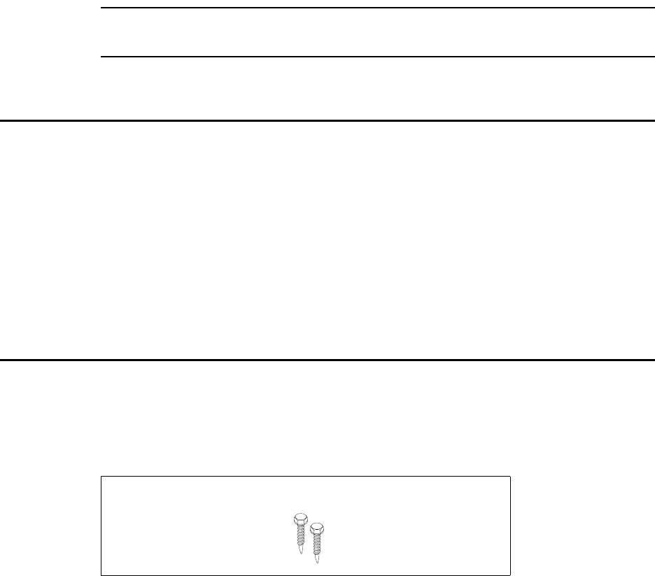
• After the holes are drilled into the building, drive the screws (illustrated in Figure 5)
through the holes on the mounting bracket and into the building.
Figure 5 illustrates the screws to use to attach the mounting bracket to the building.
Figure 5 Screws to attach mounting bracket to building
7
Figure 6 provides dimensions for drilling holes into the side of the building.
Figure 6 Mounting bracket dimensions
2X 1.25
2X 7.00
8Installing and using the Expedience OSU
Setting the OSU inside the mounting bracket
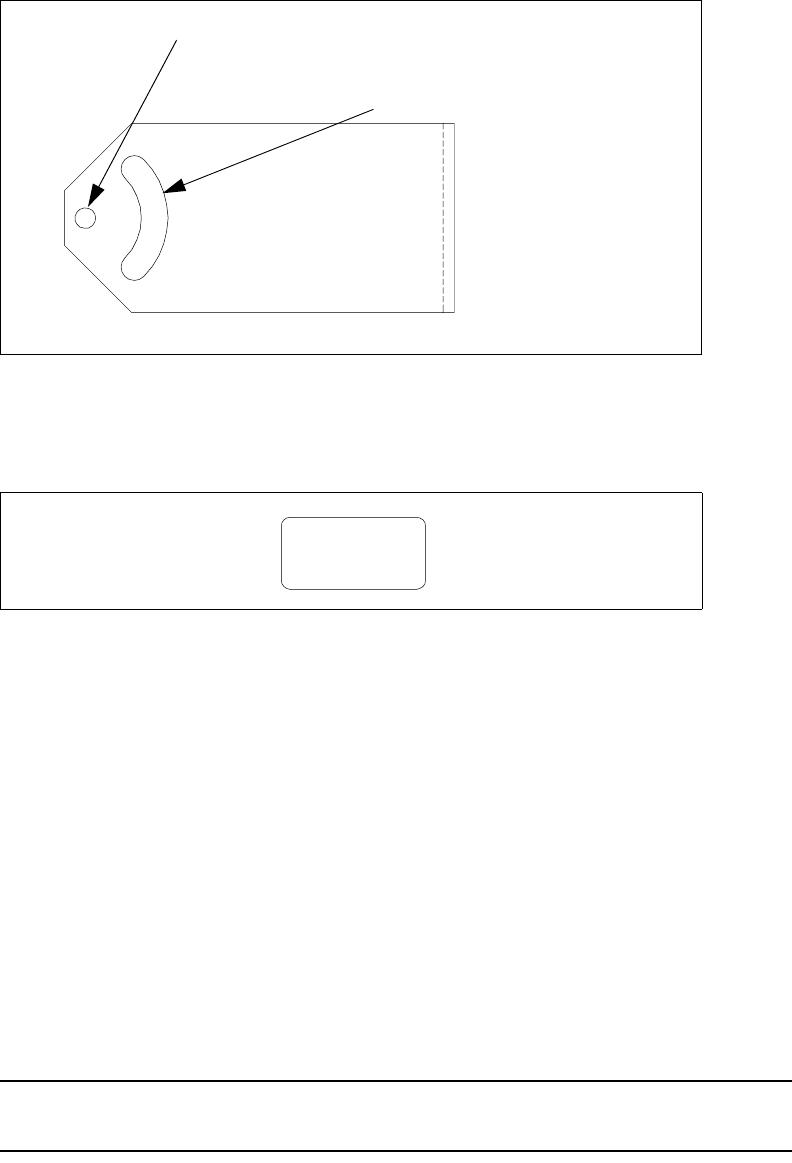
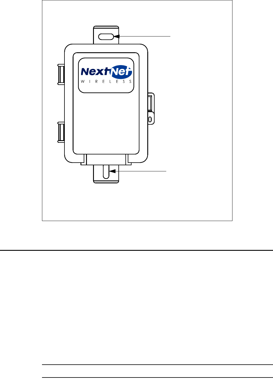
The OSU must be installed vertically. The OSU has a peg on top, and a peg on bottom. The
upper and lower pegs snap into the mounting bracket’s peg holes.
You must install the OSU vertically. To install the OSU in the mounting bracket:
1Make sure the bottom of the OSU faces the earth. This is the side of the OSU labelled with
a sticker “MOUNT THIS SIDE DOWN”. The sticker is illustrated in Figure 8.
2On the bottom arm of the mounting bracket, snap the OSU’s peg into the peg hole.
3On the top arm of the mounting bracket, snap the OSU’s upper peg into the adjustment
arch.
To accommodate the height of the peg, you may need to lift the mounting bracket’s edge
up slightly.
Partially tightening adjustment screws to hold OSU in place
To make sure the OSU doesn’t slip out of the mounting bracket, partially tighten the screws
in the adjustment arch.
If you still need to pivot the OSU along the adjustment arch—in order to find the strongest
signal from the service provider—do not fully tighten the screws yet.
You will fully tighten the screws after finding the strongest signal from the service provider.
When the screws are fully tightened, the OSU will no longer move along the adjustment arch.
Note: Before mounting the OSU in the bracket, apply an anti-seize compound to the screws
used in the assembly.
Figure 7 Adjustment arch and peg hole in mounting bracket
Figure 8 MOUNT THIS SIDE DOWN Sticker
Adjustment arch
Peg hole
MOUNT THIS
SIDE DOWN
9
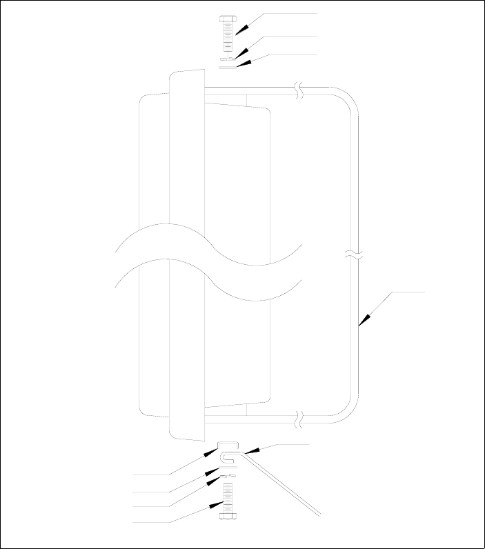
Figure 9 illustrates how the screw, split lock, flat washer and double-tab washer are put
together.
1For the top of the mounting bracket, assemble the screw (coated with anti-seize
compound), split lock washer and flat washer as shown in Figure 9.
2For the bottom of the mounting bracket, assemble the screw (coated with anti-seize
compound), split lock washer, flat washer, ground wire, and double-tab washer, as shown
in Figure 9.
Let the ground wire dangle to the ground.
3On the upper arm of the mounting bracket, insert the screw through the adjustment arch
on the mounting bracket.
4Partially tighten the screw on the OSU to hold it in place.
5On the bottom are of the mounting bracket, partially tighten the bolt on the bottom of the
OSU.
6Plug in the circular end of the OSU communication cable in the bottom of the OSU.
Provide strain relief by making a loop in the cable and strapping it to the lower part of the
mounting bracket.
Figure 9 Mounting bracket screw assembly
Screw, coated with
Split lock washer
Flat washer
Bracket
Solid ground wire
Split lock washer
Flat washer
Double tab washer
Screw, coated with
Top of unit
Bottom of unit
anti-seize compound
anti-seize compound
10 Installing and using the Expedience OSU
Note: You will fully tighten both bolts in the section, “(Optional) Finding the strongest
service provider signal” on page 13.
Running cables through building’s wall
The power cable and Ethernet cable run from inside the building to the NIM box, which you
will install in step 3.
1Near the NIM box, drill a 3/4 inch (18 mm) hole through the wall.
2Draw one end of the RJ-45 cable through the hole.
3Draw the power cable through the hole.
4Mount the power supply to the inside wall of the building. (Screws not provided.)
5Seal the hole with caulking material after completing the installation.
Attaching the NIM box to the outside of building
To attach the NIM to the outside of the building:
1Make sure the bottom of the NIM is facing the ground. A rubber grommet is installed on
the bottom of the NIM.
2The screws provided with the NIM are self-drilling.
• Drive the upper screw through the opening in the upper bracket and into the side of the
building.
• Drive the lower screw through the opening in the lower bracket and into the side of the
building.
• Make sure at least one screw is set into a stud in the wall.
• If installing the NIM box on a brick or masonry surface, use lead screw anchors.
Figure 10 Screws to attach NIM box to building
11
Figure 11 illustrates where to drive the screws through the NIM box brackets and into the
side of the building.
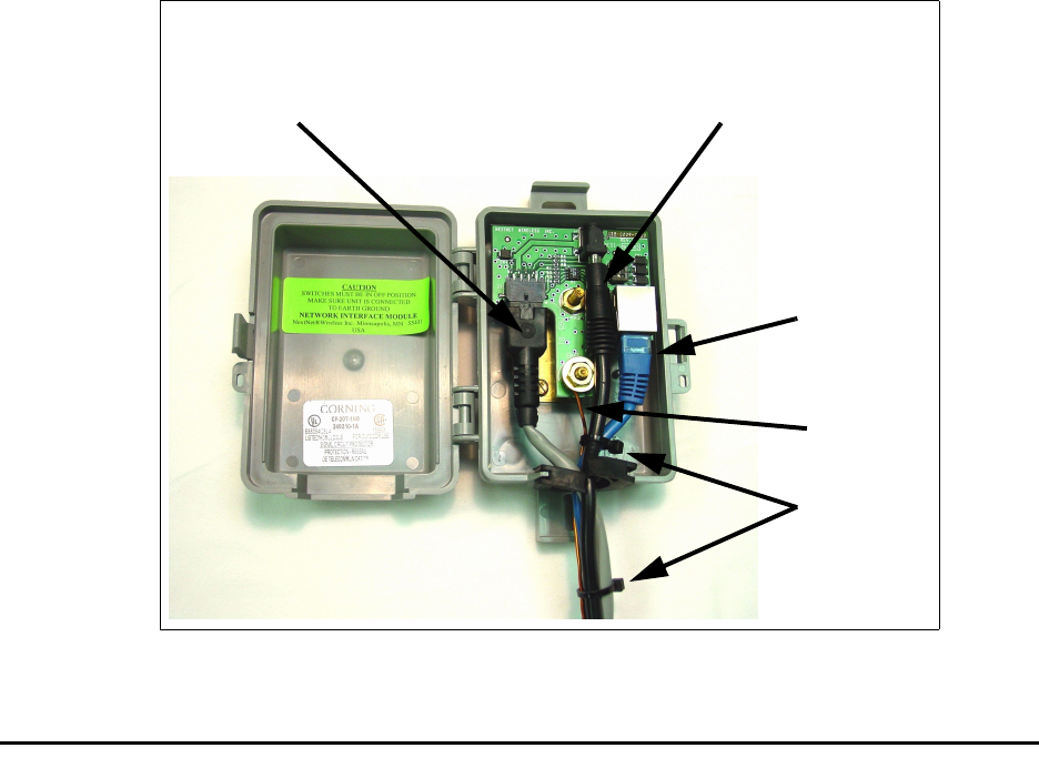
Plugging cables into NIM box
You must connect cables into the NIM box in the order shown below. Failure to connect the
cable in the proper order makes it difficult to run the cables through the rubber grommet on
the bottom of the NIM box.
It is recommended that you use a gel sealant around the grommet.
1Connect the OSU communication cable into the NIM box. This is the cable that runs
from the NIM box to the OSU device.
2Plug in the RJ-45 Ethernet cable.
3Plug in the power supply cable. This is the cable that runs from the power supply in your
building to the NIM box.
4Inside the NIM box, wire tie the power cable, RJ-45 cable, and ground wire together. Also,
wire tie all the cables and ground wire together on the outside of the NIM box.
Note: Do not plug in the power cable to the indoor power supply yet.
Figure 11 Mounting NIM to building’s exterior
Drive screw
through upper
bracket
Drive screw
through lower
bracket
12 Installing and using the Expedience OSU
Figure 12 shows the cables and the ground wire connected inside the NIM box.
Connecting ground wires
Both the OSU and the NIM box must be grounded to a ground rod in the earth near your
building. Make sure your ground cable does not exceed a 50 feet maximum to the ground rod.
To ground the NIM box and the OSU:
1Inside the NIM box, unscrew the hex nut labelled GND.
2Insert one end of the ground wire through the rubber grommet on the bottom of the NIM
box. (Make sure you are NOT using the ground wire from the OSU. Rather, use a separate
ground wire to ground the NIM.)
3Loop the ground wire around the ground post.
4Re-tighten the hex nut around the wire to hold it in place.
5Connect the other end of the ground wire to the ground rod in the ground next to the
building.
6Connect the ground wire from the OSU to the ground rod in the ground next to the
building.
7Attach all wires to the building by using electrical staples. Use drip loops as needed.
8Caulk the hole in the building with a silicone or acrylic caulk.
Figure 12 Cables and ground wire plugged into NIM box
Power cable
OSU communication cable
Ground
wire
RJ-45
cable
Cable ties

13
Plugging in power cord and RJ-45 cord
1Plug the RJ-45 cord into the NIC on your computer or switching device.
2The power cord uses standard household power. Plug the power cord in the power source.
(Optional) Finding the strongest service provider
signal
Note: The following sections describe additional methods of optimizing the orientation of
the OSU, if necessary.
The OSU is equipped with an internal antenna. To provide the best service, the OSU searches
for the strongest signal transmitted by your service provider.
You can find the strongest signal from your service provider by using one of the following
methods:
• Software-assisted method
• Sound (auditory) method
Both methods require you to install the LinkMonitor program
Installing the LinkMonitor program
1Locate the software CD supplied with your OSU.
2Insert the CD into your computer’s CD drive. If the installation program does not start
automatically, start it by clicking on the Setup.exe icon.
3Follow the instructions in the dialog boxes to complete the installation of the LinkMonitor
program.
4After the software is installed, a blue RSU icon appears in your computer’s system tray.
To run the LinkMonitor program, right click on the icon, and select Open.
Figure 13 Starting the LinkMonitor program
LinkMonitor program’s icon in
system tray
14 Installing and using the Expedience OSU
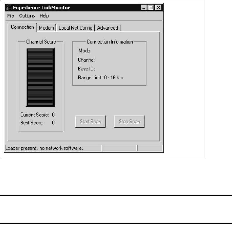
The Expedience LinkMonitor window appears (Figure 14).
Using the software-assisted method to find the strongest signal
Note: It may be beneficial to have two people perform this procedure. One person will
monitor software statistics inside the building. The other person will rotate the OSU outside
the building.
To scan for the strongest signal from your service provider:
1Install the LinkMonitor program as described in the section “Installing the LinkMonitor
program” on page 13.
2On the LinkMonitor window, click Start Scan.
3Return to the OSU on the side of the building.
4Slowly rotate the OSU along the adjustment arch. Stop the rotation at every 15 degrees for
5 seconds.
Note the score reported by the LinkMonitor program, as described in step 5.
5The LinkMonitor program searches for a signal from your service provider. In the
Channel Score group, the strength of the signal received at the starting position is
indicated in two ways:
• The indicator bar shows varying levels of red, yellow, and green. Red indicates weak
signal strength, yellow indicates moderate signal strength, and green indicates strong
signal strength.
•The Current Score field shows the signal strength. During this procedure, the program
compares the Current Score to the Best Score. Best Score indicates the strongest signal
the program has ever seen during the scanning procedure.
Figure 14 Expedience LinkMonitor window

15
6Remembering the strongest signal reported, re-orient the front of the OSU in the direction
that the OSU was pointed when the strongest signal was found.
7Tighten the screws fully that hold the OSU in place.
8Return to the LinkMonitor program. Click Stop Scan.
Using the sound (auditory) method to find the strongest signal
To use the sound (auditory) method to find the strongest signal:
1Install the LinkMonitor program as described in the section “Installing the LinkMonitor
program” on page 13.
2On the LinkMonitor window, click Start Scan.
3Return to the OSU outside. You should hear the OSU beeping.
• The OSU uses beeps to indicate the strength of the signal that the OSU can detect. The
strength of the signal detected is indicated by the frequency of the beeps as compared to
the pause between beeps. A constant beep with no pause indicates that a strong signal is
detected by the OSU. One beep followed by a long pause indicates that a signal can be
found, two beeps followed by a shorter pause indicates that a stronger signal is detected,
and so on.
• If the unit beeps twice, then pauses, then beeps twice, and so on, this indicates that the
unit is scanning for service. If this beeping pattern is not broken, this indicates that the
OSU cannot detect a signal.
4Rotate the OSU along the adjustment arch, noting how frequently the OSU beeps.
5Point the OSU in the direction where the beeps are most constant.
6Tighten the screws.
7Return to the LinkMonitor program and click Stop Scan.
Setting up the computer to receive an IP address
This section describes how to set up various Windows operating systems that might run on
the host computer so that the computer can receive an IP address.
You can set up the host computer or router so it can dynamically receive an IP address. If
desired, the subscriber can request a static IP address for the host computer or router.
Note: If the subscriber uses a non-Windows operating system, check help file of the
operating system. Most help files explain how to set up a system to use a static or dynamic IP
address.
Windows 95, Windows NT, Windows 98, Windows ME:
Setting up the network connection
1From the Start menu, select Settings. Then select Control Panel.
2In the window that appears, double click the Network icon.
3Select the TCP/IP entry for the NIC.
4Click Properties.
5Select the IP Address tab.
16 Installing and using the Expedience OSU
6Perform one of the following:
• To set up the host computer to dynamically receive an IP address from the service
provider, activate the Obtain an IP Address automatically radio button.
• To set up the host computer to have a static IP address:
a Activate the Use the following IP address radio button.
bIn the Use the Following IP Address group, complete the fields, as appropriate.
7To close the windows, click OK.
8Turn off your computer.
Windows 2000: Setting up the network connection
1From the Start menu, select Settings. Then select Network and Dial-up Connections.
2Right click the connection you want to alter; that is, the name of your NIC. From the pop-
up menu, select Properties.
3The Local Area Connection Properties window appears. Select the Internet Protocol
(TCP/IP) item. Click Properties.
4Perform one of the following:
• To set up the host computer to dynamically receive an IP address from the service
provider, activate the Obtain an IP Address automatically radio button.
• To set up the host computer to have a static IP address:
a Activate the Use the following IP address radio button.
bIn the Use the Following IP Address group, complete the fields, as appropriate.
5To close the window, click OK.
6On the remaining open window, click OK again.
7Turn off your computer.
Windows XP: Setting up the network connection
1From the Start menu, select Settings. Then select Network Connections.
2Right click the connection you want to alter; that is, the name of your NIC. From the pop-
up menu, select Properties.
3The Local Area Connection Properties window appears. Select the Internet Protocol
(TCP/IP) item. Click Properties.
4Perform one of the following:
• To set up the host computer to dynamically receive an IP address from the service
provider, activate the Obtain an IP Address automatically radio button.
• To set up the host computer to have a static IP address:
a Activate the Use the following IP address radio button.
bIn the Use the Following IP Address group, complete the fields, as appropriate.
5To close the window, click OK.
6On the remaining open window, click OK again.
7Turn off your computer.

17
Configuring IP address assignment for routers
For instructions on how to assign a static IP address to a router, or to set up the router to use
DHCP to receive an IP address, refer to the documentation that accompanied the device.
Connecting to the Internet
To connect to the Internet:
Start your Internet browser, and try to open a few Internet sites.
• If you can open numerous sites, enjoy your new, high-speed service.
• If yon cannot open any sites—for example if your browser displays a message “This page
cannot be displayed” for all the sites you tried to access—refresh the OSU’s connection, as
described in the section “Refreshing the OSU’s connection” on page 17.
Refreshing the OSU’s connection
When you refresh the OSU’s connection, your service provider is assigning your computer a
new IP address. You need to refresh your OSU’s connection with your service provider when
your Internet browser does not let you open any Internet sites.
Windows users: Refreshing the connection
The OSU’s connection is refreshed when you restart the computer. To refresh the
connection without restarting the computer:
1Make sure you have installed the LinkMonitor program.
2In the system tray, right click the blue RSU icon (Figure 13) and select Open.
3In the window that appears, on the Local Net Config tab, click the Renew IP Address
button.
Non-Windows users: Refreshing the connection
If you do not run the Windows operating system, you can reboot your computer to refresh
the connection. You may want to refer to your operating system’s help files to determine if
other methods exist to refresh the connection (that is, to find a method for refreshing the IP
address).
Connecting the OSU to a network
Note: Use only one OSU on a network. Do not use multiple OSUs on the same network.
To directly connect the OSU to a computer, use an Ethernet cable (also known as a straight-
through cable).
However, to connect the OSU to a hub or switch, use an Ethernet cable appropriate for your
network device. This might be a straight through or cross-over cable, depending on how your
18 Installing and using the Expedience OSU
network device switches signals. When determining how to set up your network, remember
that the OSU device operates as a hub or a bridge.
After connecting the OSU to the network device, power the OSU and scan for a service
provider signal, as described in earlier sections of this guide.

19
FCC information
NOTICE: This equipment has been tested and found to comply with the Radio Frequency
Radiation Exposure Limits detailed below. A minimum of 20 centimeters (8 inches)
separation between the OSU and the operator and all other persons should be maintained.
Radio Frequency Radiation Exposure Limits
f = frequency in MHz
* = Plane-wave equivalent power density
Note: NOTE 1 to Table 1: Occupational/controlled limits apply in situations in which
persons are exposed as a consequence of their employment provided those persons are fully
aware of the potential for exposure and can exercise control over their exposure.
Limits for occupational/controlled exposure also apply in situations when an individual is
transient through a location where occupational/controlled limits apply provided he or she is
made aware of the potential for exposure
Note: NOTE 2 to Table 1: General population/uncontrolled exposures apply in situations in
which the general public may be exposed, or in which persons that are exposed as a
consequence of their employment may not be fully aware of the potential for exposure or
cannot exercise control over their exposure.
Declaration of Conformity Compliance Information
Class B computer peripheral
This device complies with part 15 of the FCC Rules. Operation is subject to the following
two conditions: (1) This device may not cause harmful interference, and (2) this device must
accept any interference received, including interference that may cause undesired operation.
Table 1 Limits for Maximum Permissible Exposure (MPE)
Frequency range
(MHz)
Electric field
strength
(V/m)
Magnetic field
strength
(A/m)
Power
density
(mW/cm2)
Averaging
time (minutes)
(A) Limits for Occupational/Controlled Exposures
0.3-3.0 614 1.63 *(100) 6
3.0-30 1842/f 4.89/f *(900/f2)6
30-300 61.4 0.163 1.0 6
300-1500 — — f/300 6
1500-100,000 — — 5 6
(B) Limits for General Population/Uncontrolled Exposure
0.3-1.34 614 1.63 *(100) 30
1.34-30 824/f 2.19/f *(180/f2)30
30-300 27.5 0.073 .2 30
300-1500 — — f/1500 30
1500-100,000 — — 1.0 30
20 Installing and using the Expedience OSU
Responsible Party: NextNet Wireless, Inc.
9555 James Ave. South Suite 270
Bloomington, MN 55431
952-929-4008
Note: This equipment has been tested and found to comply with the limits for a Class B
digital device, pursuant to part 15 of the FCC Rules. These limits are designed to provide
reasonable protection against harmful interference in a residential installation. This
equipment generates, uses and can radiate radio frequency energy and, if not installed and
used in accordance with the instructions, may cause harmful interference to radio
communications. However, there is no guarantee that interference will not occur in a
particular installation. If this equipment does cause harmful interference to radio or television
reception, which can be determined by turning the equipment off and on, the user is
encouraged to try to correct the interference by one or more of the following measures:
• Reorient or relocate the receiving antenna.
• Increase the separation between the equipment and receiver.
• Connect the equipment into an outlet on a circuit different from that to which the receiver
is connected.
• Consult the dealer or an experienced radio/TV technician for help.
Note: Modification of this device may void the user’s authority to operate the equipment.
21
A
anti-seize compound 1
C
cable diagram 4
computer
NIC requirement 1
cross-over cable 17
G
ground wires
connecting 12
grounding rod 1
grounding wire
recommended 1
I
IP address
renewing 17
IP address (host computer)
refreshing 17
L
LAN
connecting to OSU 17
LinkMonitor program 13
M
mounting bracket
attaching to house 6
drilling template 7
screw assembly 9
N
network device
connecting to OSU 17
NIC requirement 1
NIM box
attaching to house 10
choosing installation location 2
grounding 1
O
OSU
bottom 8
choosing installation location 2
connecting to network 17
installing inside mounting bracket 8
min. separation distance of equipment and
persons 19
package components 1, 2
P
part numbers list 1, 2
power cord
running through house 10
R
RJ-45 cable
plugging in 13
running through house 10
router
connecting to OSU 17
S
service provider signal
finding strongest 13
switch
connecting to OSU 17
I
NDEX
22 Installing and using the Expedience OSU