Nokia Solutions and Networks PCS002 User Manual IMN BTSE BS11
Nokia Solutions and Networks IMN BTSE BS11
UserManual.wiki
>
Nokia Solutions and Networks
>
PCS002 User Manual
>
BS11 Installation
Contents
1.
User manuals index
2.
BS11 Introduction
3.
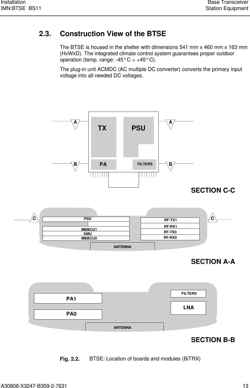
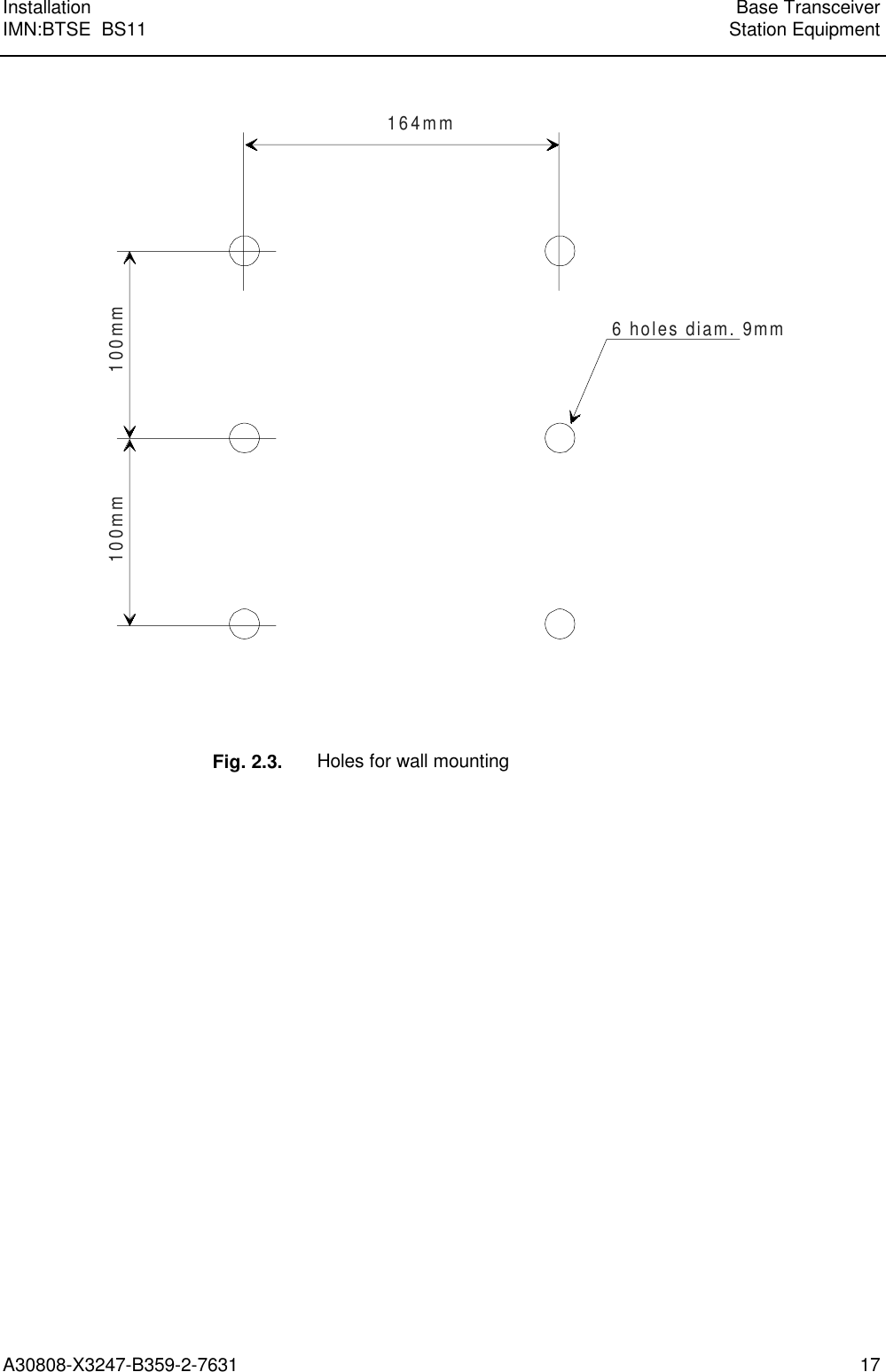
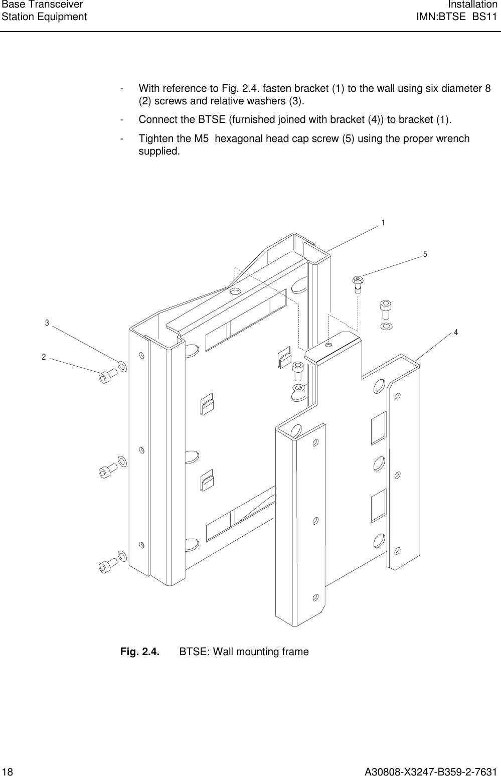
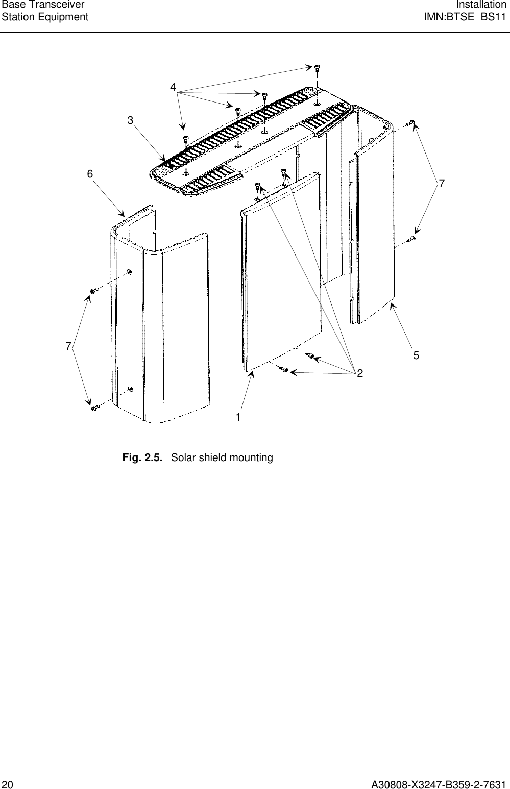
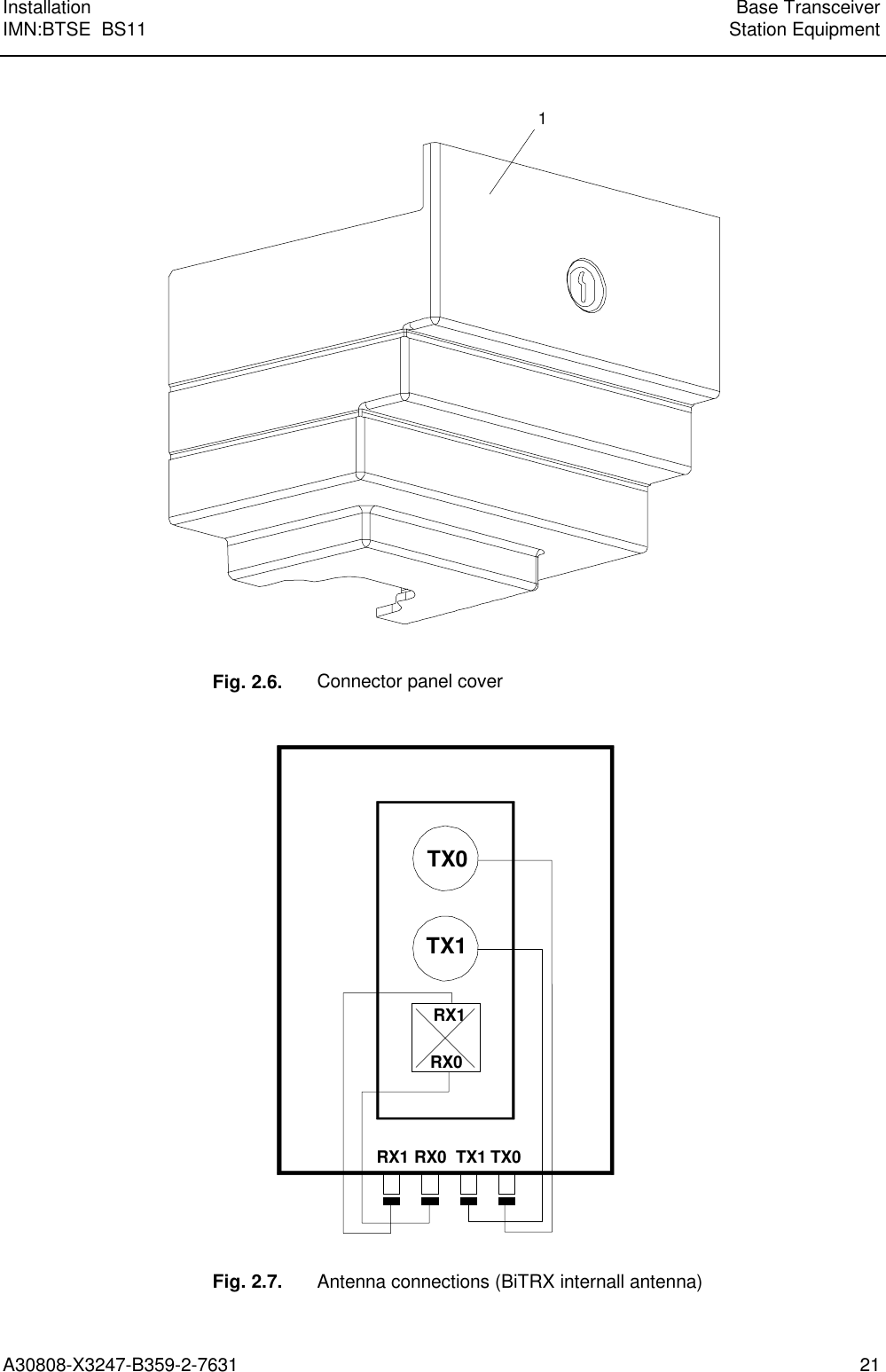
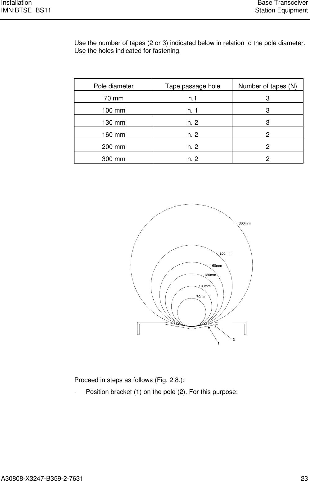
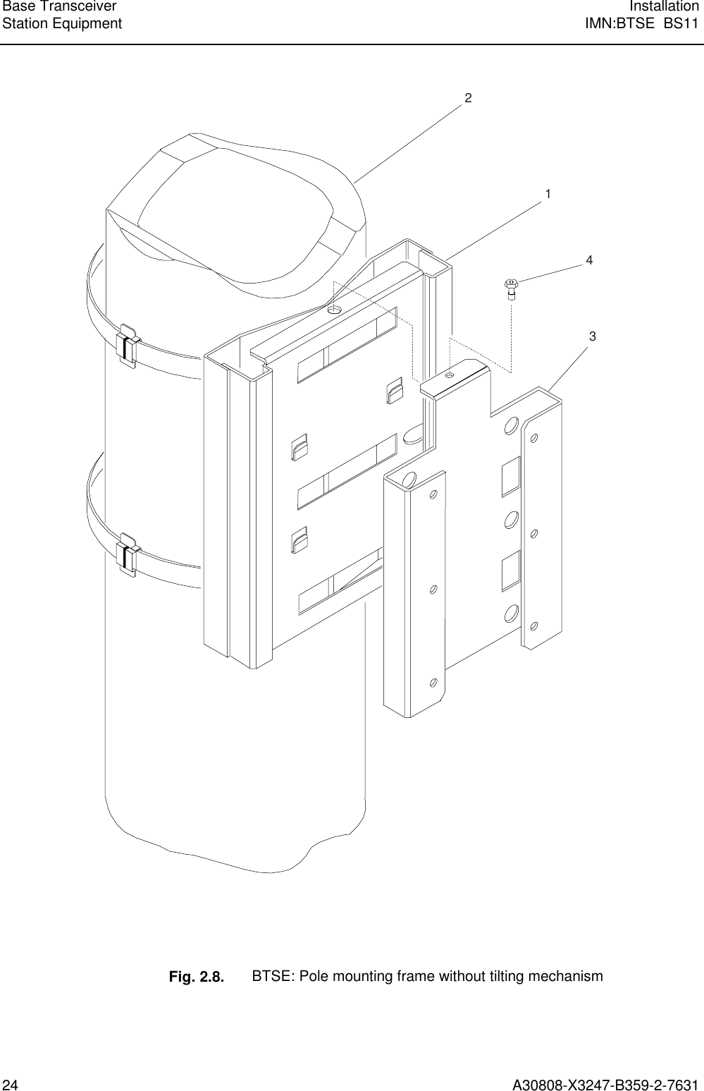
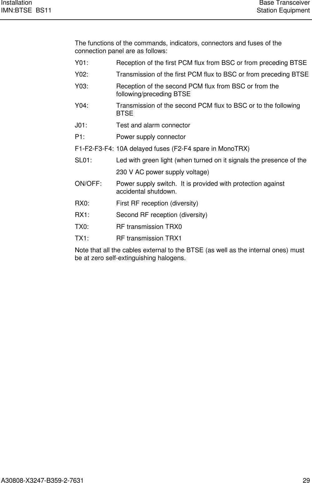
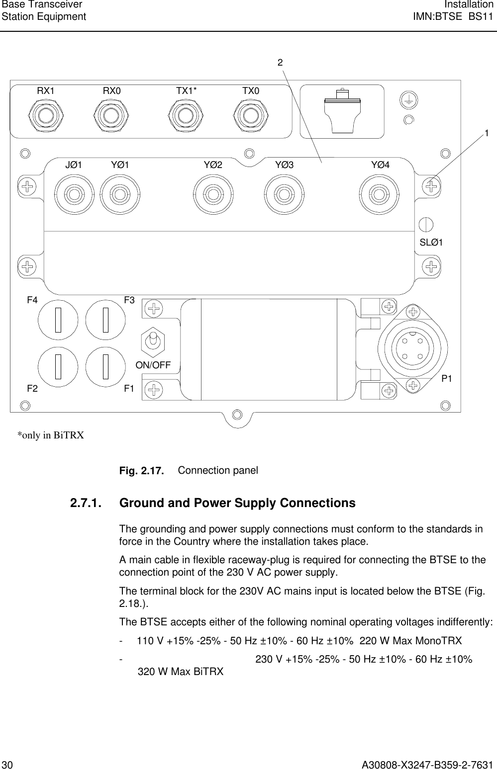
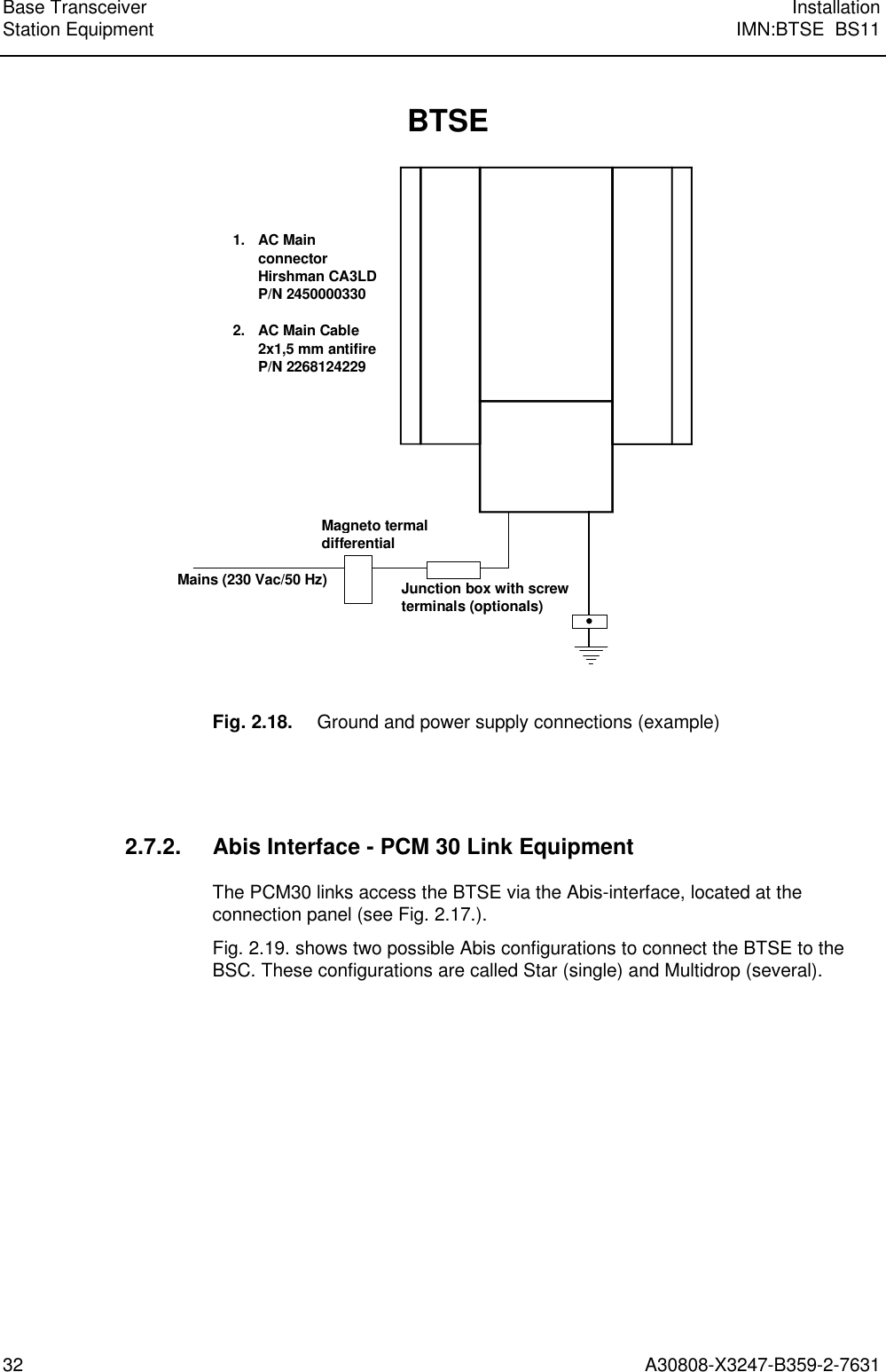
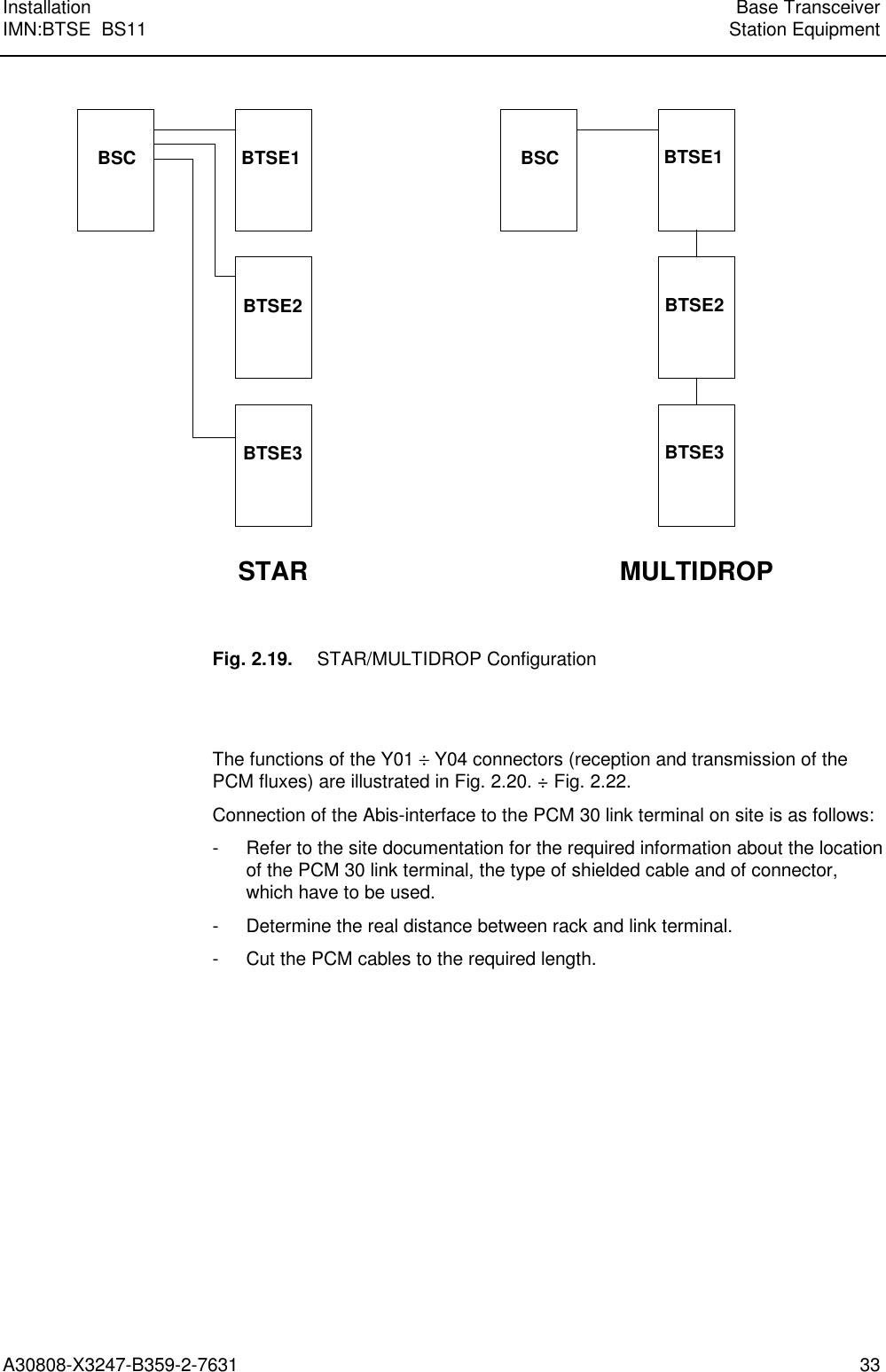
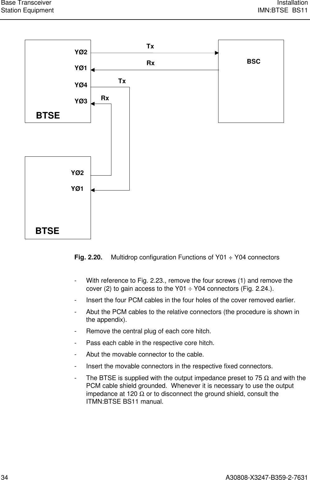
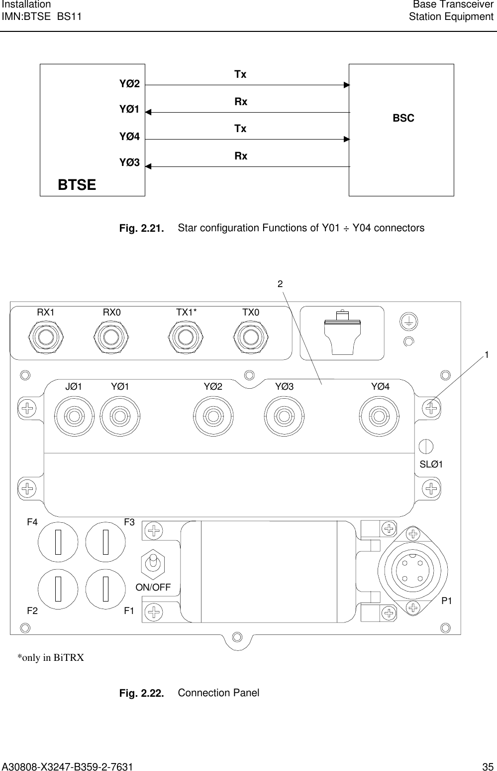
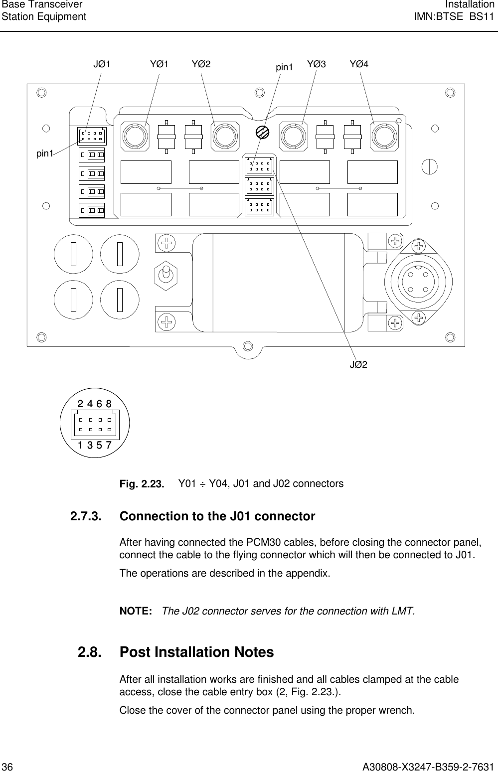
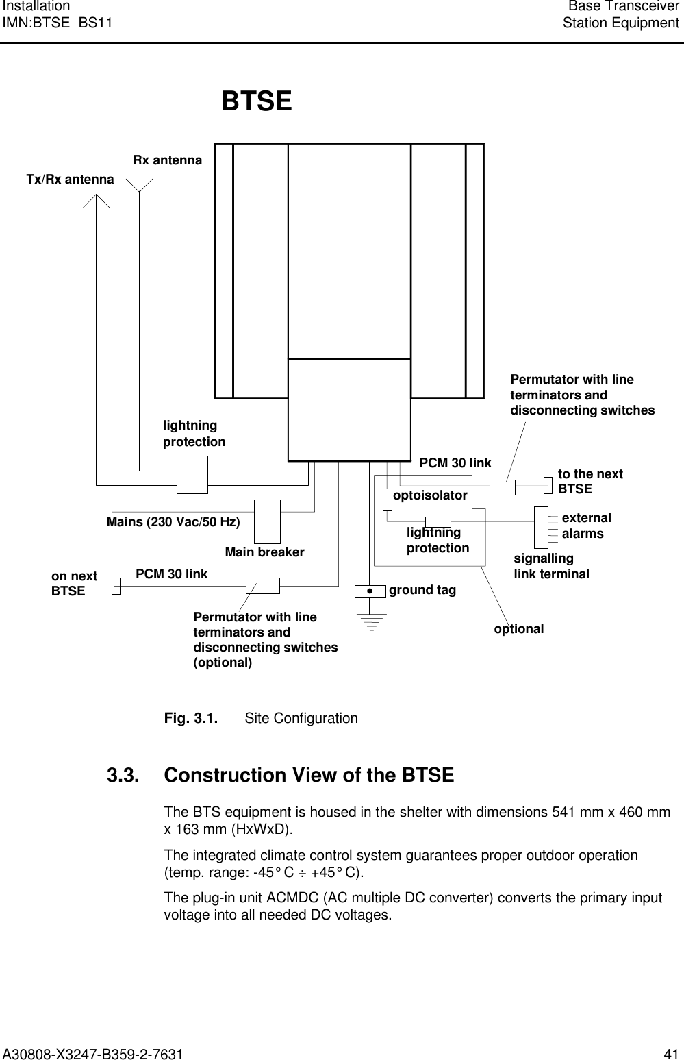
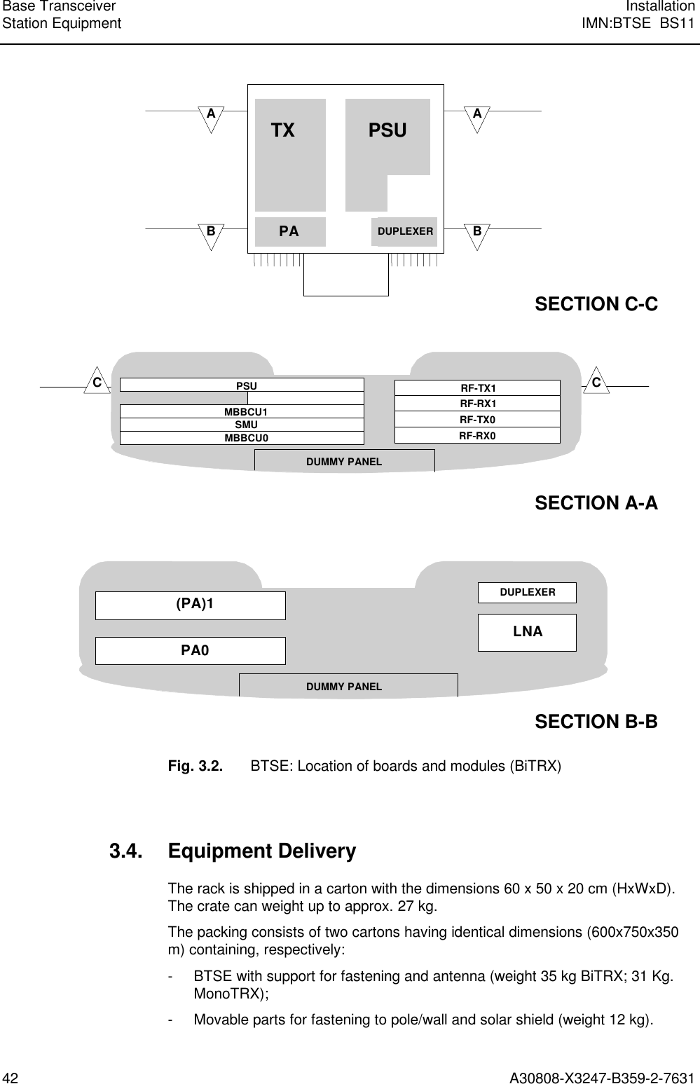
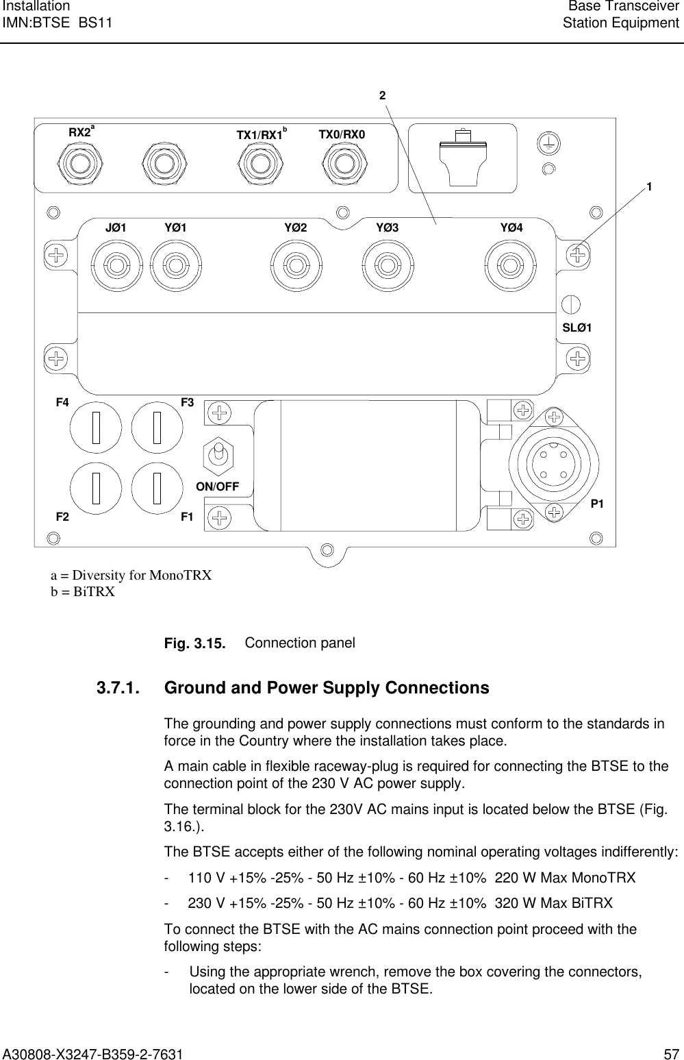
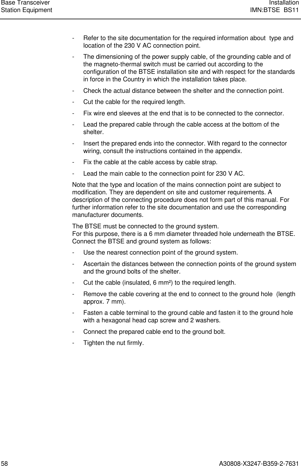
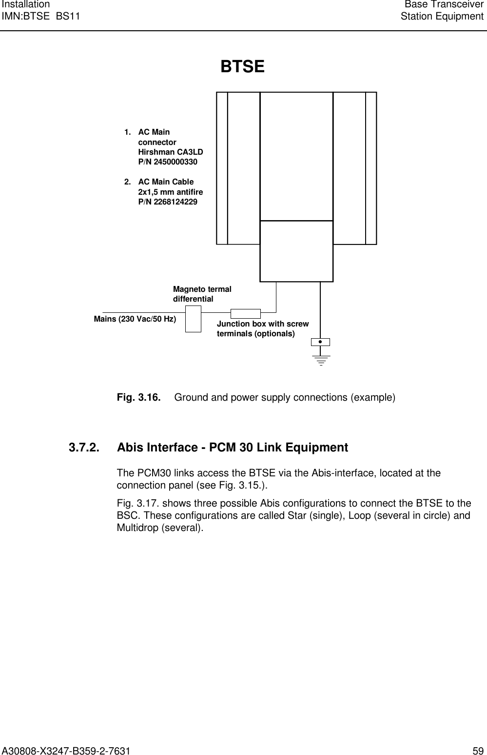
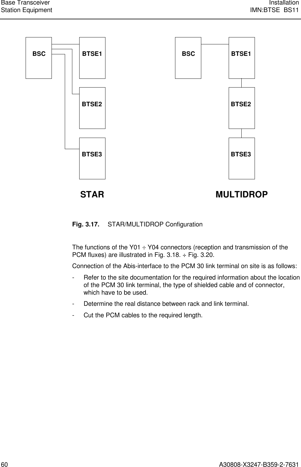
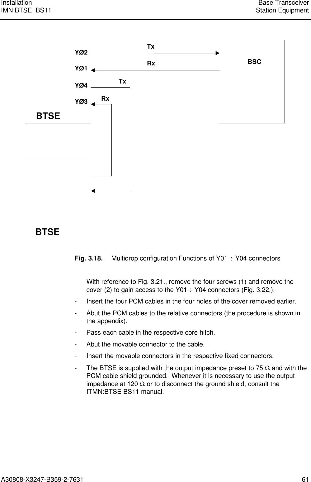
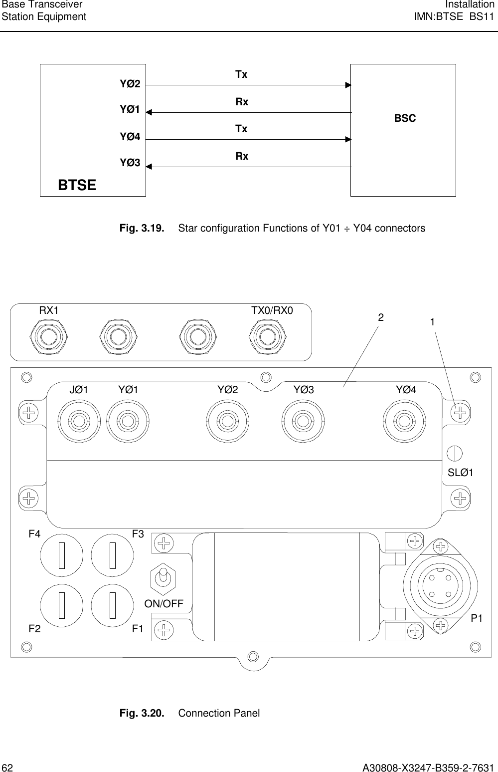
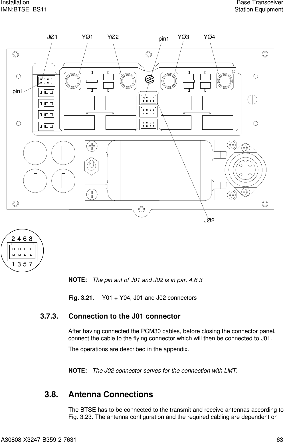
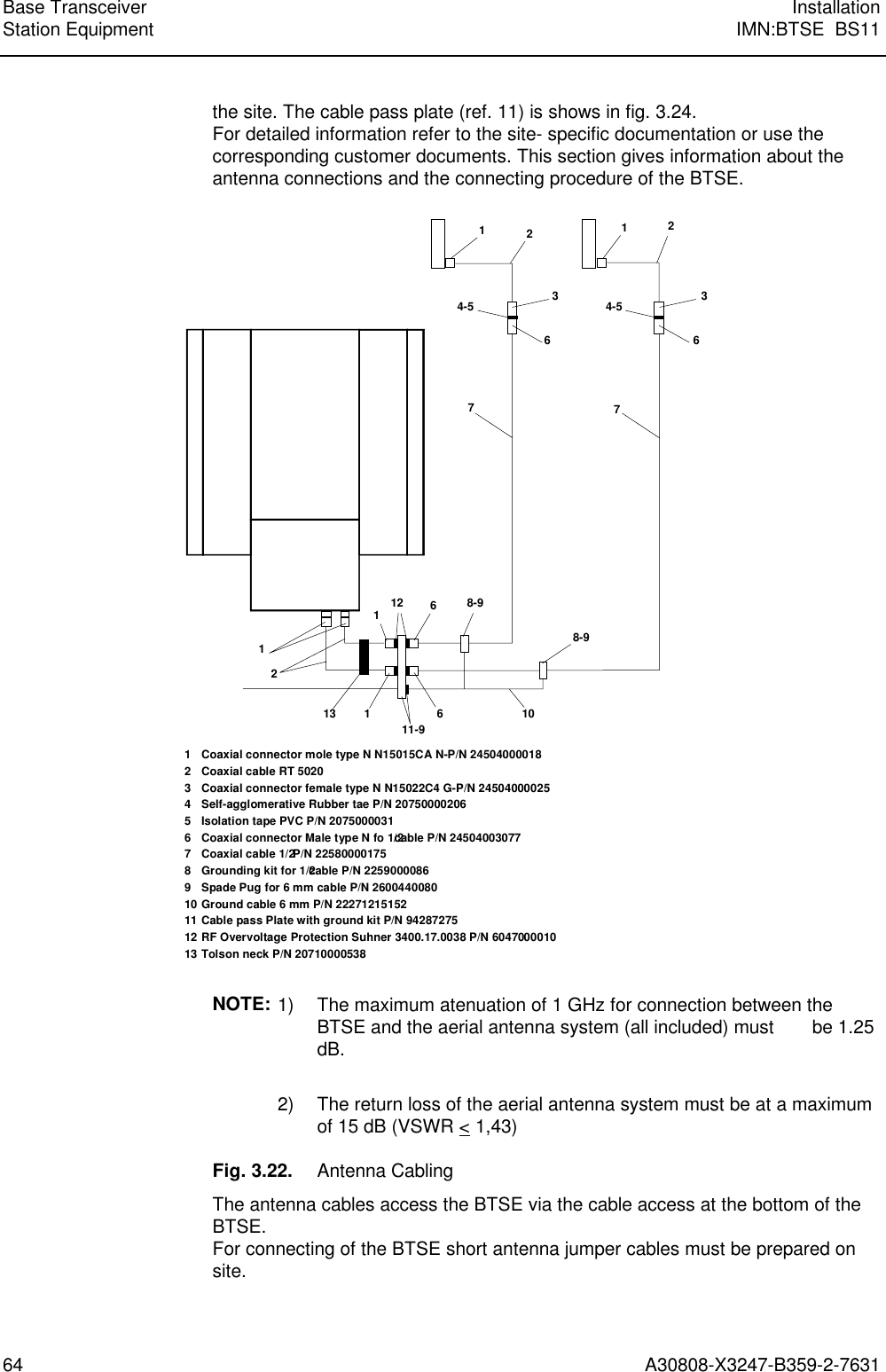
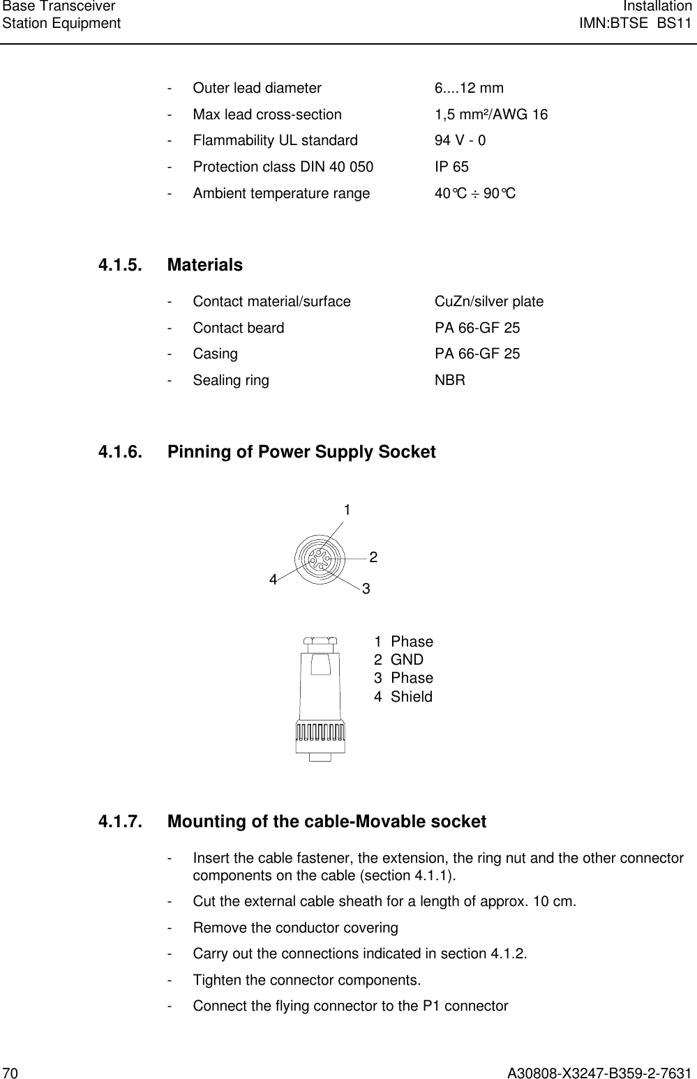
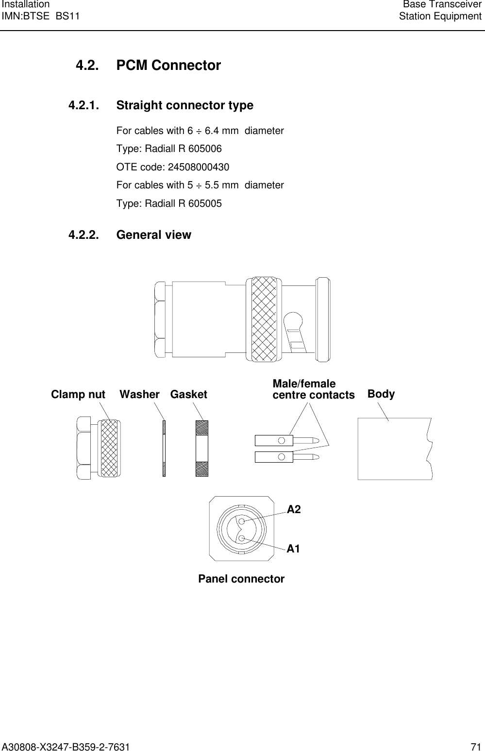
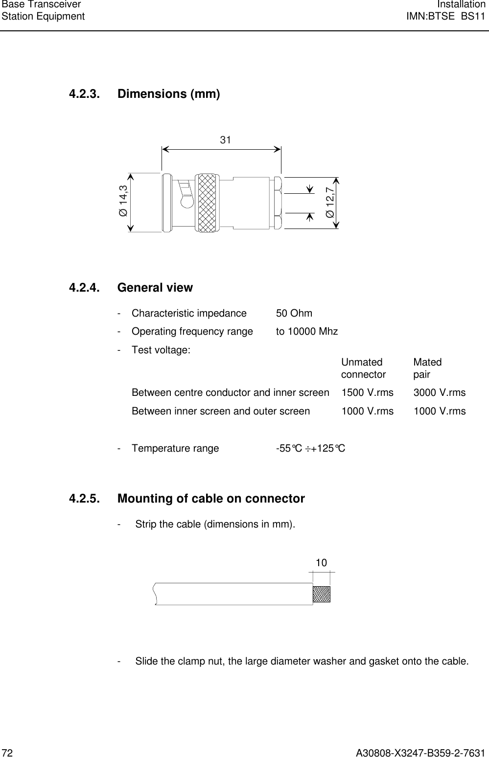
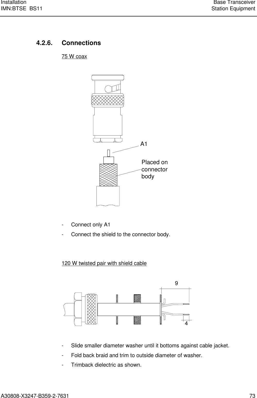
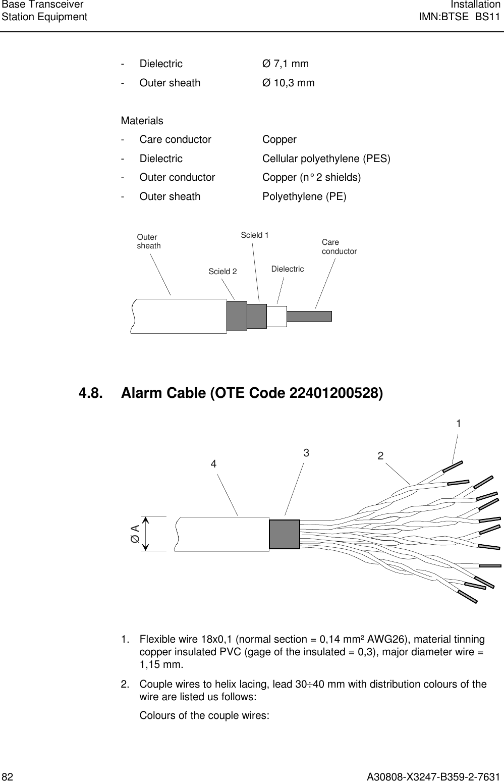
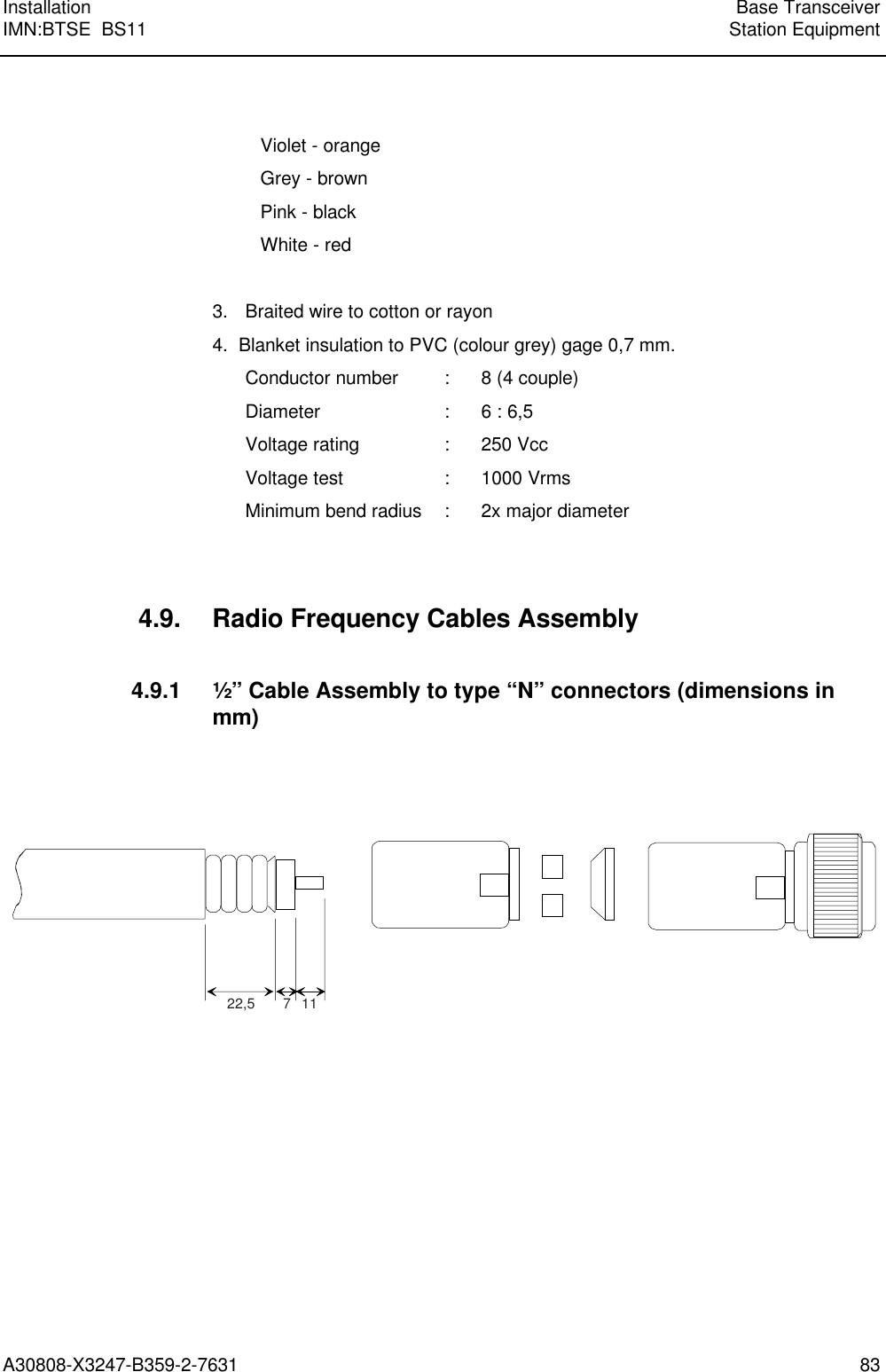
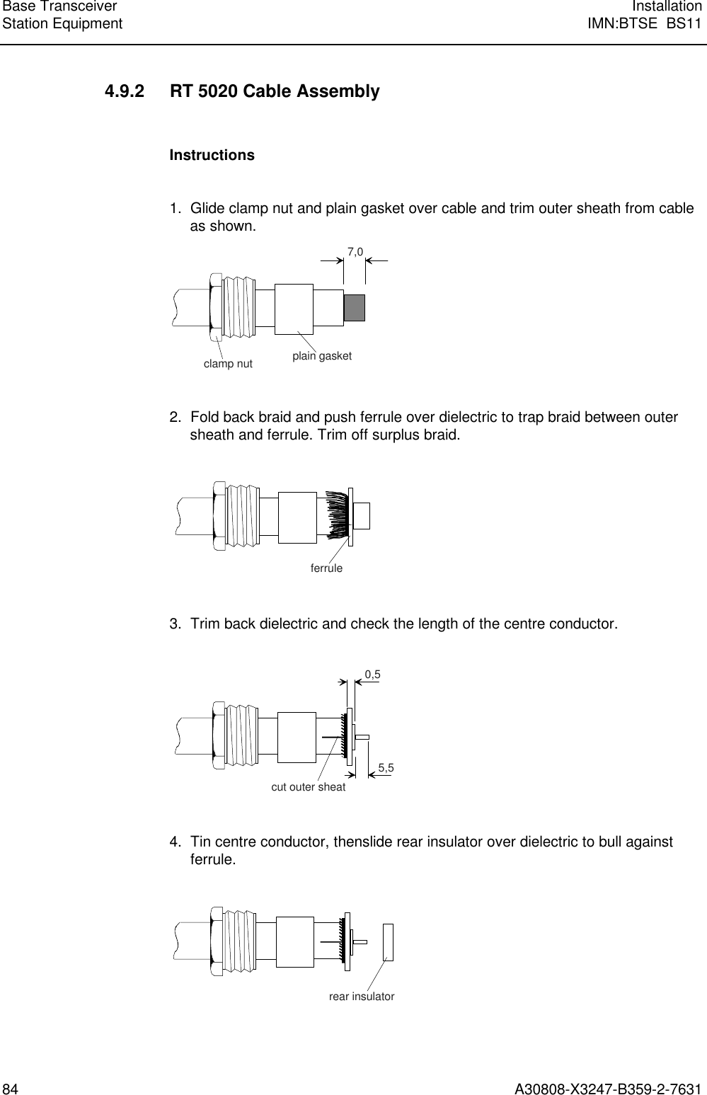
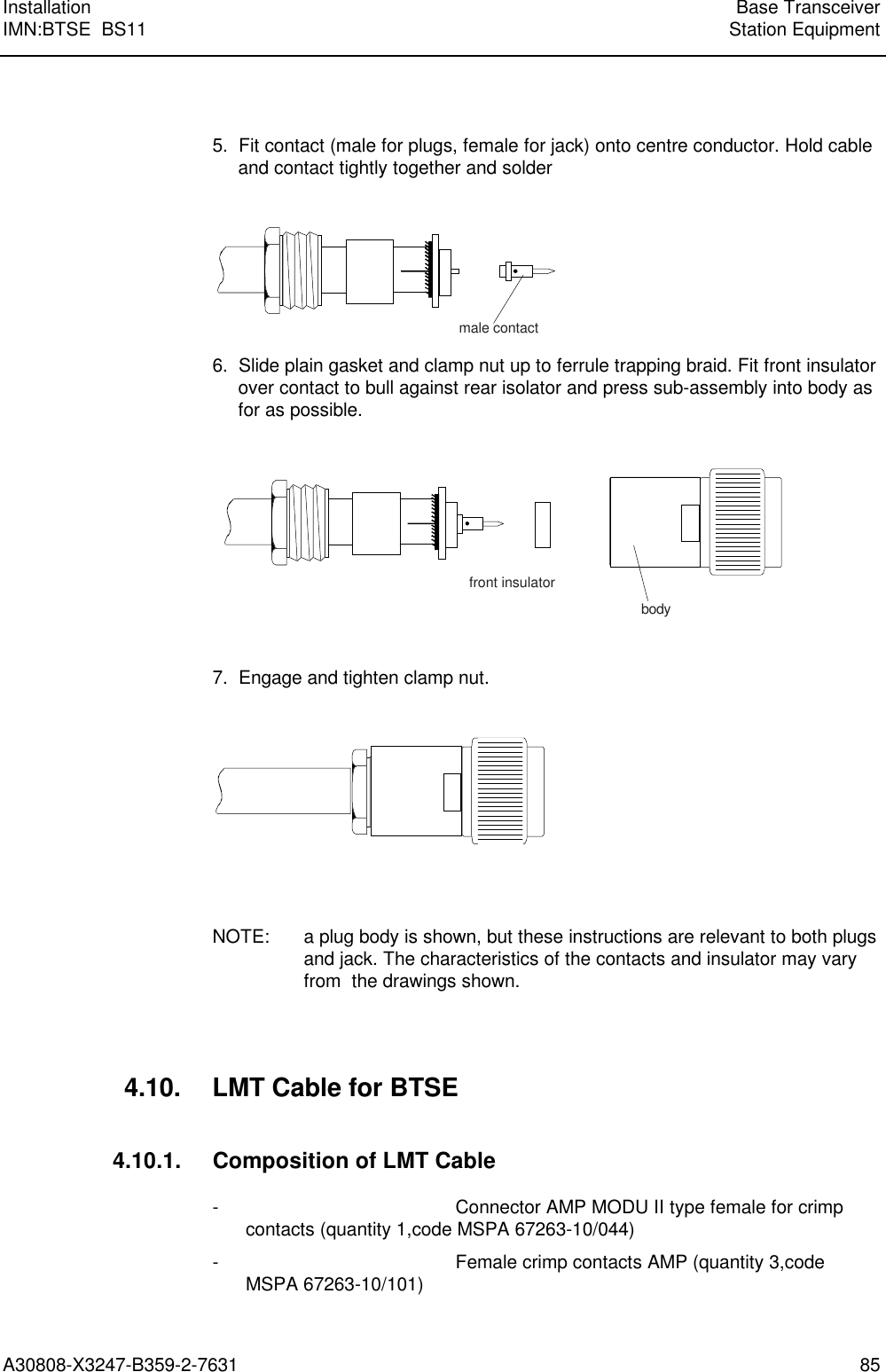
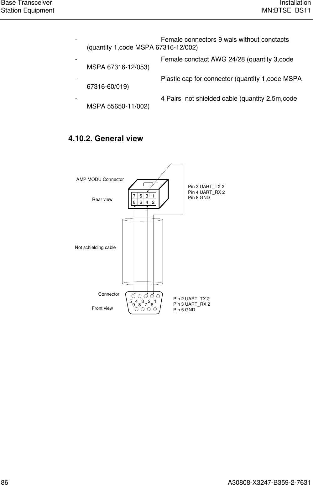
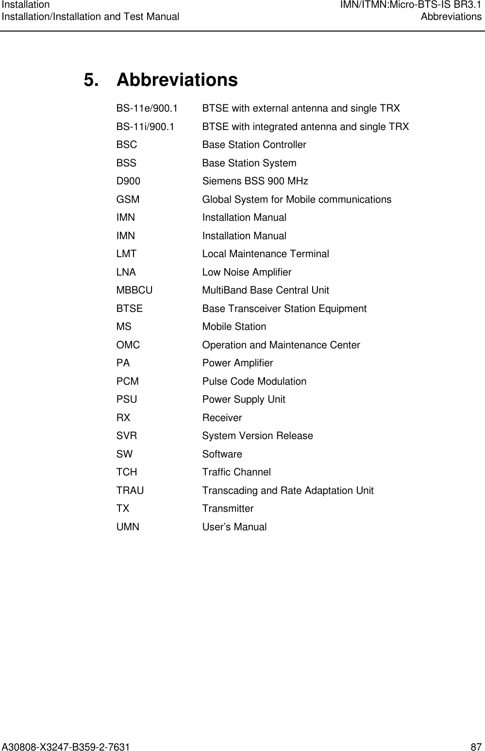
BS11 Installation
4.
BS11 Installation test
BS11 Installation
Navigation menu
Upload a User Manual
Namespaces
Wiki Guide
HTML
PDF
Info
Views
User Manual
Discussion / Help
Navigation