Nokia Solutions and Networks T4KJ1 LTE 700 MHz Public Safety Base Station Transceiver User Manual Exhibit 8 Users Manual print
Nokia Solutions and Networks LTE 700 MHz Public Safety Base Station Transceiver Exhibit 8 Users Manual print
Contents
- 1. Exhibit 8 Users Manual
- 2. Exhibit 8 Users Manual (print)
Exhibit 8 Users Manual (print)

APPLICANT: MOTOROLA
Cellular Networks
FCC ID: IHET4KJ1
Users Manual Exhibit
LTE WBR FDD Frame Based Radio @ 700MHz
FCC Filing – LTE WBR FDD Frame Based Radio @ 700MHz


Accuracy
Copyrights
Restrictions
License Agreements
High Risk Materials
Trademarks
Motorola
Customer
Network Resolution Center contact information.

■■■■■■■■■■■■■■■■■■■■■■■■■■■■■■■■■■■■■■■■■■■■■■■■■■■■■■■■■■■■■
■
■
■
■

■■■■■■■■■■■■■■■■■■■■■■■■■■■■■■■■■■■■■■■■■■■■■■■■■■■■■■■■■■■■■
■
■
■
■

■■■■■■■■■■■■■■■■■■■■■■■■■■■■■■■■■■■■■■■■■■■■■■■■■■■■■■■■■■■■■
■
■
■
■

■■■■■■■■■■■■■■■■■■■■■■■■■■■■■■■■■■■■■■■■■■■■■■■■■■■■■■■■■■■■■
■
■
■
■

■■■■■■■■■■■■■■■■■■■■■■■■■■■■■■■■■■■■■■■■■■■■■■■■■■■■■■■■■■■■■
■
■

■■■■■■■■■■■■■■■■■■■■■■■■■■■■■■■■■■■■■■■■■■■■■■■■■■■■■■■■■■■■■
■
■
NOTE

Characters typed in at the keyboard are shown like this sentence.
Items of interest within a command appear like this sentence.
Messages, prompts, file listings, directories, utilities, and environmental
variables that appear on the screen are shown like this sentence.
Items of interest within a screen display appear like this sentence.
■■■■■■■■■■■■■■■■■■■■■■■■■■■■■■■■■■■■■■■■■■■■■■■■■■■■■■■■■■■■■
■
■
Customer Network Resolution Center
contact information

■■■■■■■■■■■■■■■■■■■■■■■■■■■■■■■■■■■■■■■■■■■■■■■■■■■■■■■■■■■■■
■
■
■
■
■■■■■■■■■■■■■■■■■■■■■■■■■■■■■■■■■■■■■■■■■■■■■■■■■■■■■■■■■■■■■
■
■

Chapter 1 — Introduction
Chapter 2 — Site Preparation
Chapter 3 — Frame-based eNodeB Installation
Chapter 4 — Installation of the indoor portions of the Remote RF based
eNodeB
Chapter 5 — Installation of the RRH
Chapter 6 — Cabling of the RRH
Chapter 7 — Power-up sequence
Chapter 8 — Field Replaceable Units
■■■■■■■■■■■■■■■■■■■■■■■■■■■■■■■■■■■■■■■■■■■■■■■■■■■■■■■■■■■■■
■
■
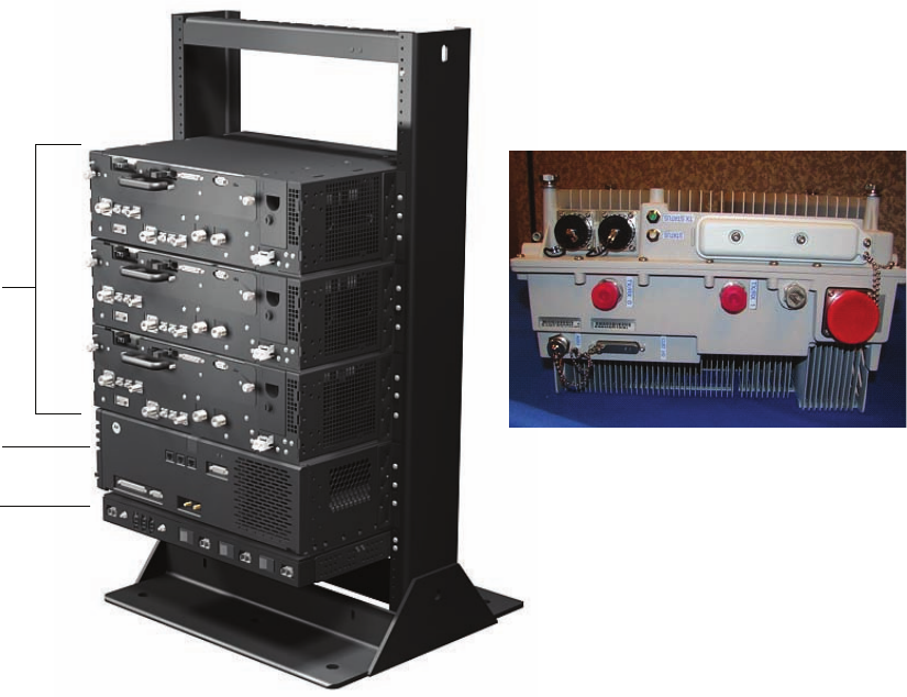
E1_majorcomponents_eNodeB.eps
3X
Radio Shelves
Remote Radio Head
BCUII
PDU

Radio Fan Tray
Ground Lug
Power InputRF Filter
(behind front panel)

■■■■■■■■■■■■■■■■■■■■■■■■■■■■■■■■■■■■■■■■■■■■■■■■■■■■■■■■■■■■■
■
■

■■■■■■■■■■■■■■■■■■■■■■■■■■■■■■■■■■■■■■■■■■■■■■■■■■■■■■■■■■■■■
■
■
■
■

■■■■■■■■■■■■■■■■■■■■■■■■■■■■■■■■■■■■■■■■■■■■■■■■■■■■■■■■■■■■■
■
■

Continued

Continued

NOTE
NOTE

■■■■■■■■■■■■■■■■■■■■■■■■■■■■■■■■■■■■■■■■■■■■■■■■■■■■■■■■■■■■■
■
■


■■■■■■■■■■■■■■■■■■■■■■■■■■■■■■■■■■■■■■■■■■■■■■■■■■■■■■■■■■■■■
■
■

E1_SysPwrCabling1.eps
RACK
MGB Rack
Customer
Supplied
Customer
Supplied
Customer
Power
+27 V
PDU
+27 V Radio Shelf
Radio Shelf
Radio Shelf
BCU
AE
AC
AC
AC
AL
AL
**
** When using a Motorola rack, only the BCU and the frame need to be cabled to the MGB.
When using a non-Motorola rack, all items must be cabled to the MGB.
RRH STYLE 1
MGB
Customer
Supplied
Customer
Supplied
Customer
Power
-48 V
PDU
-48 V
RRH
RRH
RRH
BCU Surge suppressors
and filters *
Building
Entrance/Exit
AE
AK
AK
AK
AB
AB
AB
AL
AL
* Surge suppressors and filters are customer supplied.
MGB = Master Ground Bus
RRH STYLE 2
MGB
Customer
Supplied
Customer
Supplied
Customer
Power
-48 V RRH
RRH
RRH
BCU
Surge suppressors
and filters *
Building
Entrance/Exit
AB
AB
AB
AL
* Surge suppressors and filters are customer supplied.
MGB - Master Ground Bus
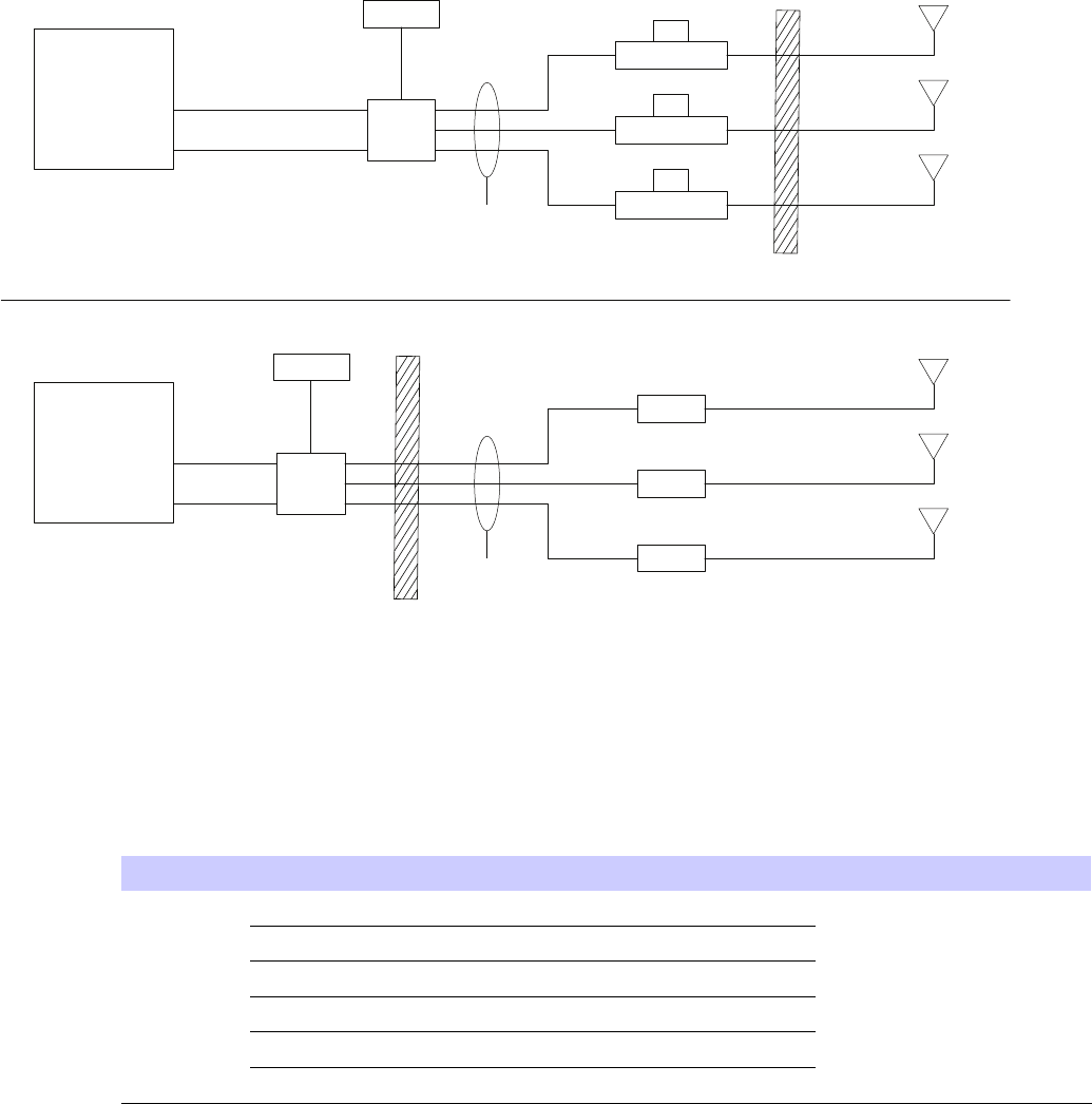
E1_eNodeB_SysdataCable1.eps
RRH
Customer
Termination
Customer I/O
Ethernet
BCU
Fiber Optic
RFGPS
AM
AA RRH
RRH
RRH
Customer
Supplied
Antenna
RF
AA
AA
AG
AN Customer
Supplied
Antenna
RF
Customer
Supplied
Antenna
RF
RACK
Customer
Termination
Customer I/O
Ethernet
BCU
Fiber Optic
RFGPS
AM
AD
AF *
* Cable AF connects RF signal between the
TRANSMIT OUT and TX on the Radio Shelf.
Radio Shelf
AF *
Radio Shelf
AF *
Radio Shelf
Customer
Supplied
Antenna
RF
AD
AD
AG
AN Customer
Supplied
Antenna
RF
Customer
Supplied
Antenna
RF
Building
Entrance/Exit
Building
Entrance/Exit
Continued

■■■■■■■■■■■■■■■■■■■■■■■■■■■■■■■■■■■■■■■■■■■■■■■■■■■■■■■■■■■■■
■
■

■■■■■■■■■■■■■■■■■■■■■■■■■■■■■■■■■■■■■■■■■■■■■■■■■■■■■■■■■■■■■
■
■
■
■
■■■■■■■■■■■■■■■■■■■■■■■■■■■■■■■■■■■■■■■■■■■■■■■■■■■■■■■■■■■■■
■
■
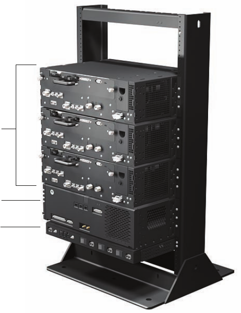
E1_majorcomponents_eNodeB.eps
3X
Radio Shelves
BCUII
PDU
Radio Fan Tray
Ground Lug
Power InputRF Filter
(behind front panel)
■■■■■■■■■■■■■■■■■■■■■■■■■■■■■■■■■■■■■■■■■■■■■■■■■■■■■■■■■■■■■
■
■
■■■■■■■■■■■■■■■■■■■■■■■■■■■■■■■■■■■■■■■■■■■■■■■■■■■■■■■■■■■■■
■
■

NOTE
NOTE
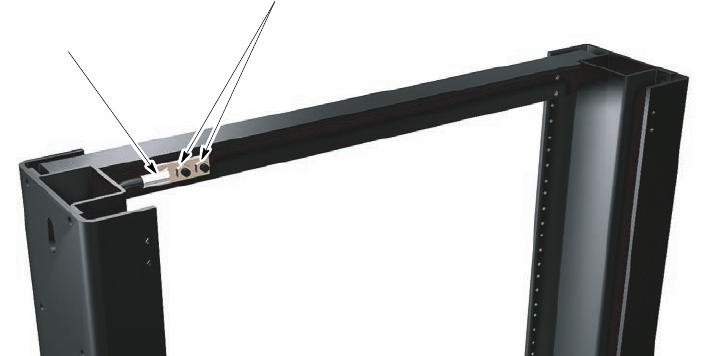
Earth Ground
Terminal Studs
Ground Cable With
2-hole Lug Fastened
To Ground Terminals
Rack
(top/rear view, shown
partially cut away)

■■■■■■■■■■■■■■■■■■■■■■■■■■■■■■■■■■■■■■■■■■■■■■■■■■■■■■■■■■■■■
■
■
NOTE
NOTE
Continued

NOTE
NOTE
NOTE
Continued

NOTE
NOTE
Continued
NOTE
ti-cdma-05694.eps
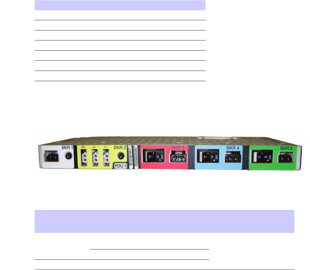
PDU front.eps
■■■■■■■■■■■■■■■■■■■■■■■■■■■■■■■■■■■■■■■■■■■■■■■■■■■■■■■■■■■■■
■
■
ti-cdma-05694.eps

NOTE
NOTE
Continued
NOTE
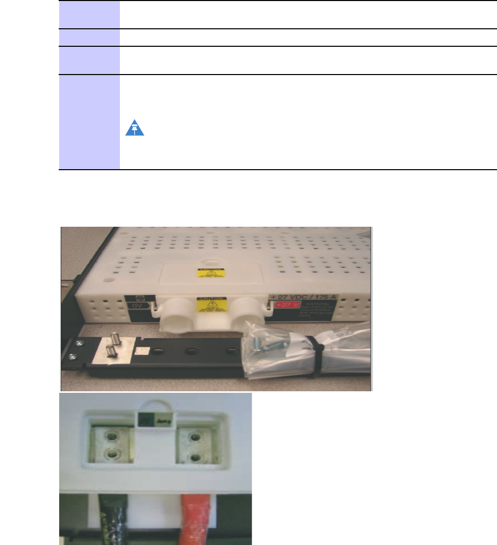
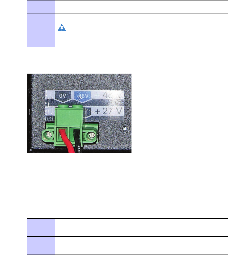
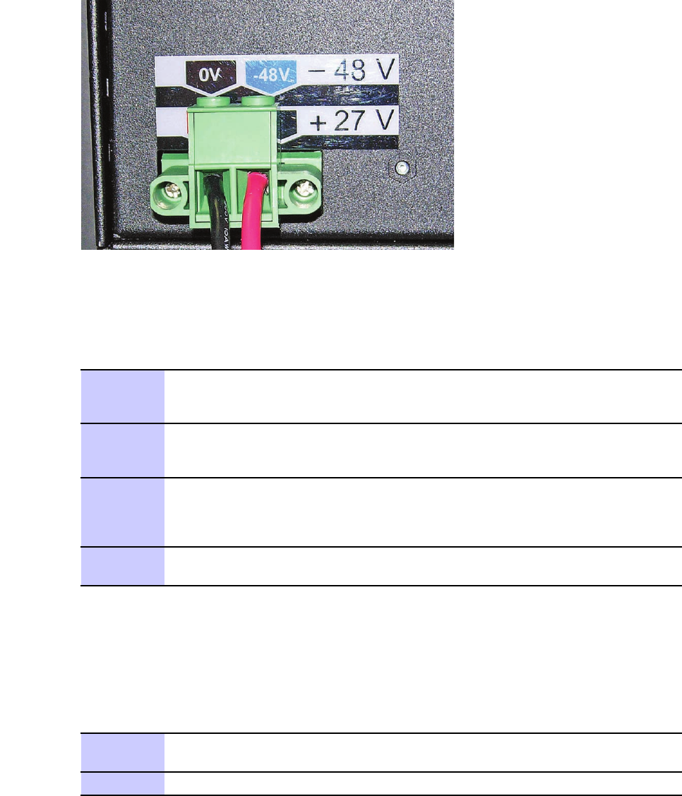
-27V.eps
Continued

NOTE
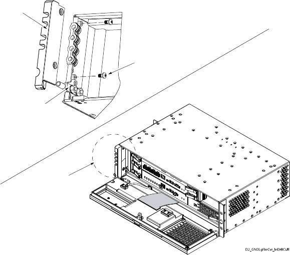
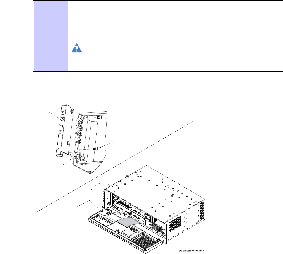
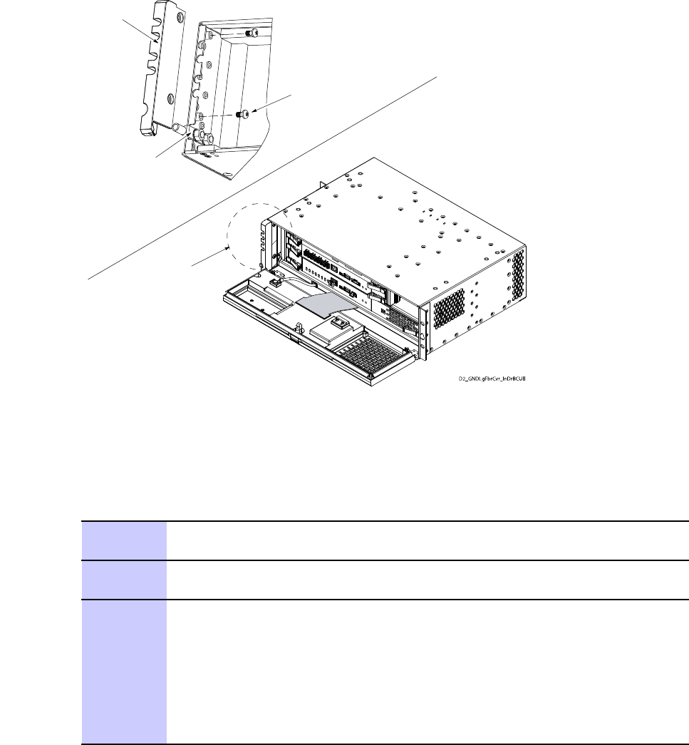
Fiber Cover
Ground Lug
2X Screws
See Detail A
Detail A
■■■■■■■■■■■■■■■■■■■■■■■■■■■■■■■■■■■■■■■■■■■■■■■■■■■■■■■■■■■■■
■
■
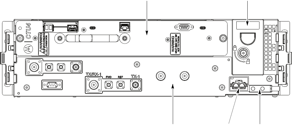
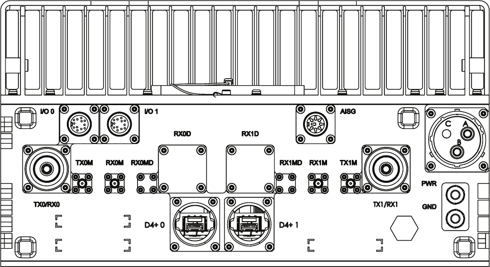
FRONT VIEW LTE_shelf_frt.eps
0V
+27V
TRANSMIT STATUS
TRANSMIT
OUT 0
KIT
NUMBER
SERIAL
NUMBER
TX-1
TX/RX-0
LTE
FWD REF
VSWR
TX-0 TX/RX-1 FWD REF
MODULE STATUS
CONTROL
PROCESSOR
TRANSMIT
OUT 1
D4+0
D4+1
D4+0
ENET
D4+1
VSWR+27V
0V GND
TX/RX-0 TX -0FWD REF
TX/RX-1 TX -1
FWD REF
FAN TRAY
TRANSMIT
STATUS
MODULE
STATUS
CONTROL
PROCESSOR
ENET
TRANSMIT
OUT 1
TRANSMIT
OUT 0
D4+0
D4+0
LED
D4+1
LED
D4+1
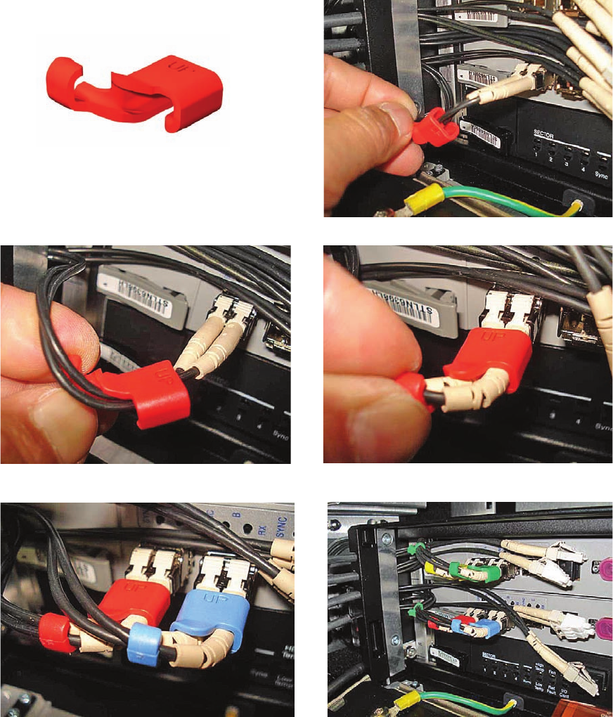
CABLE
CLIP
CABLE
CLIP

NOTE
NOTE
NOTE


NOTE
NOTE
M6 Nuts

■■■■■■■■■■■■■■■■■■■■■■■■■■■■■■■■■■■■■■■■■■■■■■■■■■■■■■■■■■■■■
■
■
CAUTION
Continued

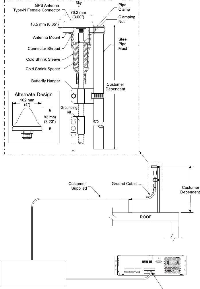
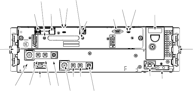
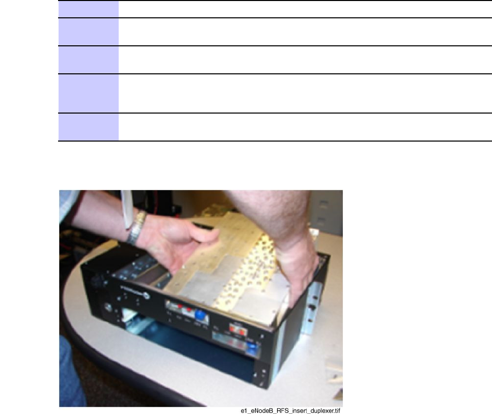
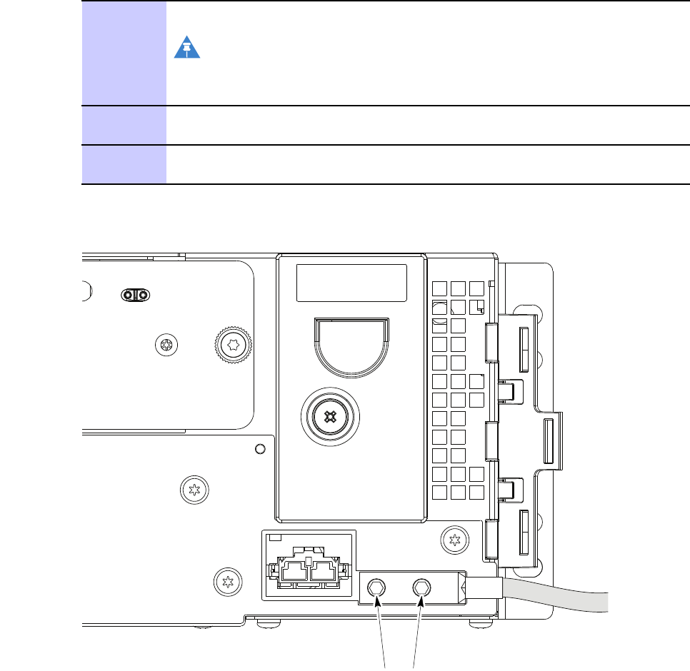
E1_eNodeB_RFGPS_cbl.eps
Surge Suppressor
Customer Supplied
Typ ically installed at
entrance to building
Customer
Supplied RF-GPS Connector
CUSTOMER I/O AP CONTROL
ENET -A ENET -B CUST. ENET
TDD RF-GPS
RGPS
STATUS
BCU II
■■■■■■■■■■■■■■■■■■■■■■■■■■■■■■■■■■■■■■■■■■■■■■■■■■■■■■■■■■■■■
■
■
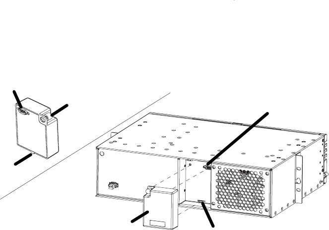
ti-cdma-05694.eps
ti-cdma-05694.eps
Mounting Tab Slot
Q-HSO
Q-HSO
Rear View
9-Pin Sub-D Connector
9-Pin Sub-D Connector
Captive Thumbscrew
Mounting Tab

NOTE

■■■■■■■■■■■■■■■■■■■■■■■■■■■■■■■■■■■■■■■■■■■■■■■■■■■■■■■■■■■■■
■
■
■
■
■■■■■■■■■■■■■■■■■■■■■■■■■■■■■■■■■■■■■■■■■■■■■■■■■■■■■■■■■■■■■
■
■
ti-cdma-05694.eps

NOTE
NOTE
NOTE
-48V.eps
Continued
NOTE
Fiber Cover
Ground Lug
2X Screws
See Detail A
Detail A

■■■■■■■■■■■■■■■■■■■■■■■■■■■■■■■■■■■■■■■■■■■■■■■■■■■■■■■■■■■■■
■
■
■
■

■■■■■■■■■■■■■■■■■■■■■■■■■■■■■■■■■■■■■■■■■■■■■■■■■■■■■■■■■■■■■
■
■
Continued
Continued
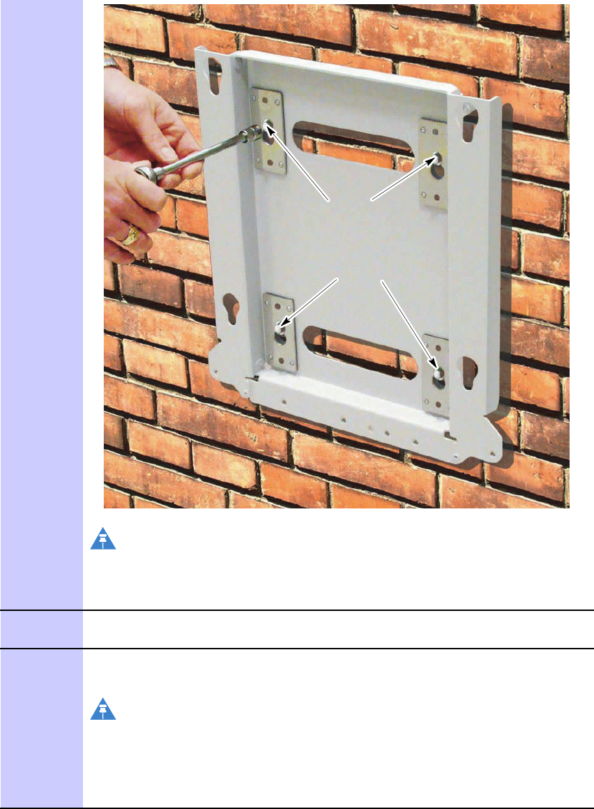
Step 2
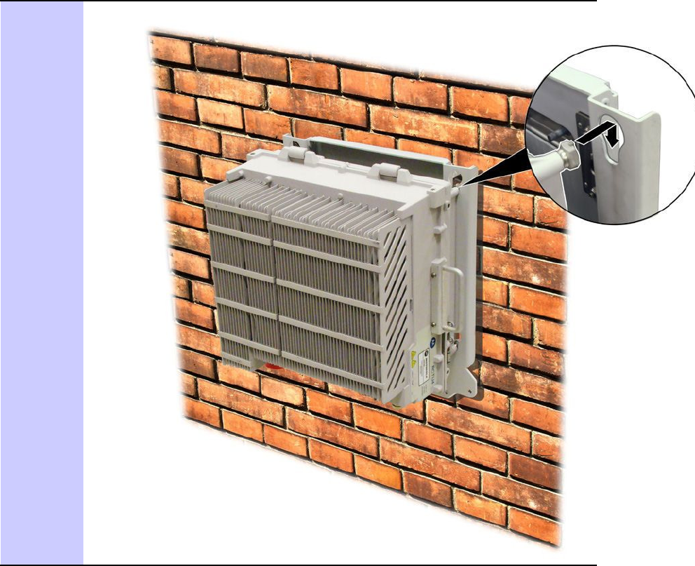
Step 4
NOTE
NOTE
Continued
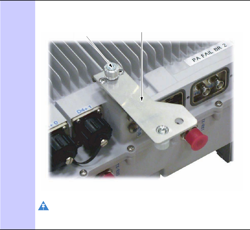
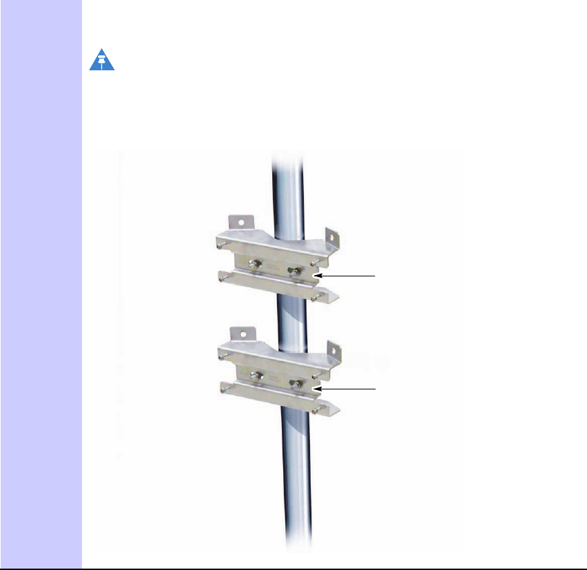
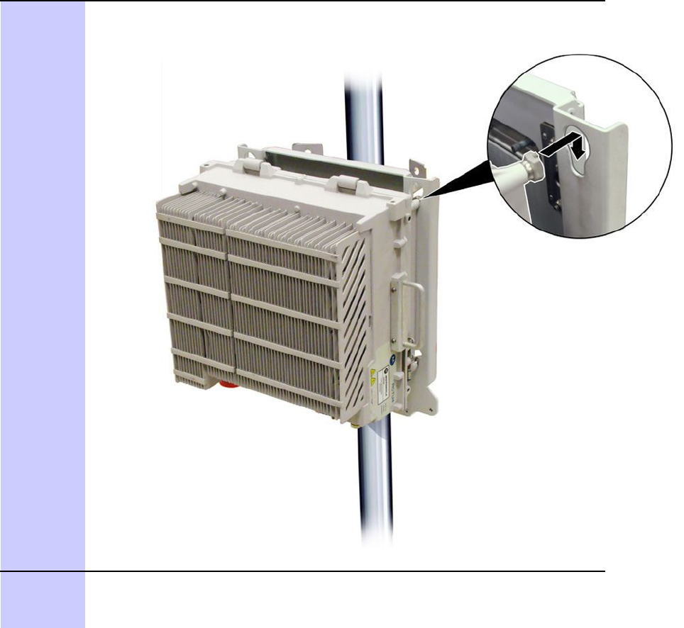
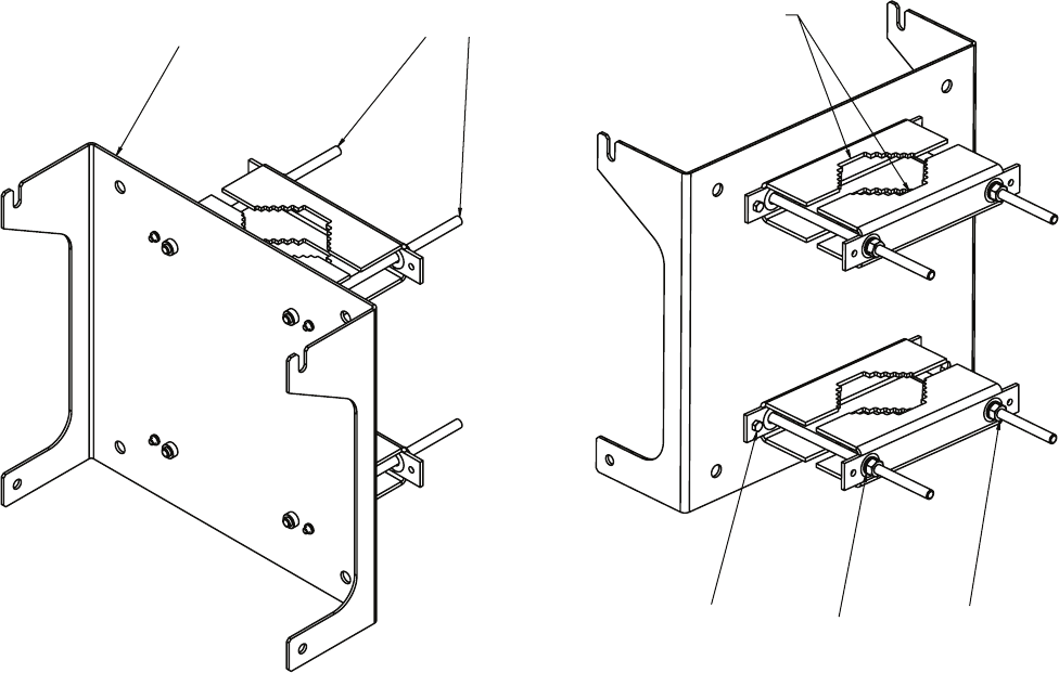
Captive M6 fastener
RRH Securing Bracket
NOTE
Continued
Continued
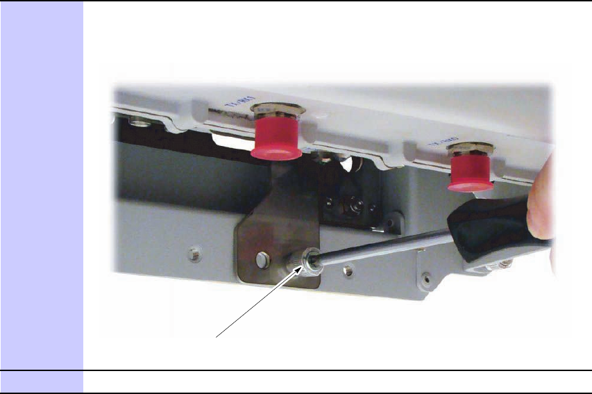
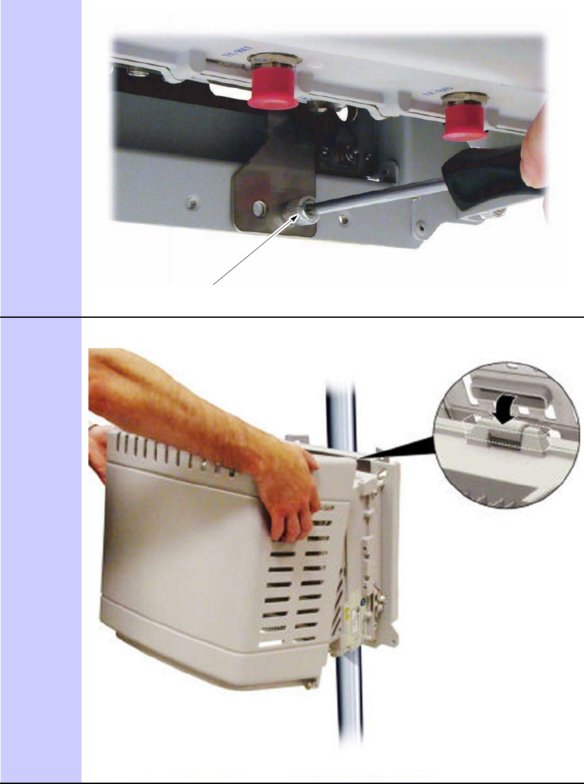
Captive M6 fastener
Continued

Continued
Continued
NOTE
Location for optional band installation
Location for optional band installation
Continued

Continued

Captive M6 fastener
RRH Securing Bracket
NOTE
Continued
Continued
Captive M6 fastener
Continued
Continued
WARNING

CAUTION
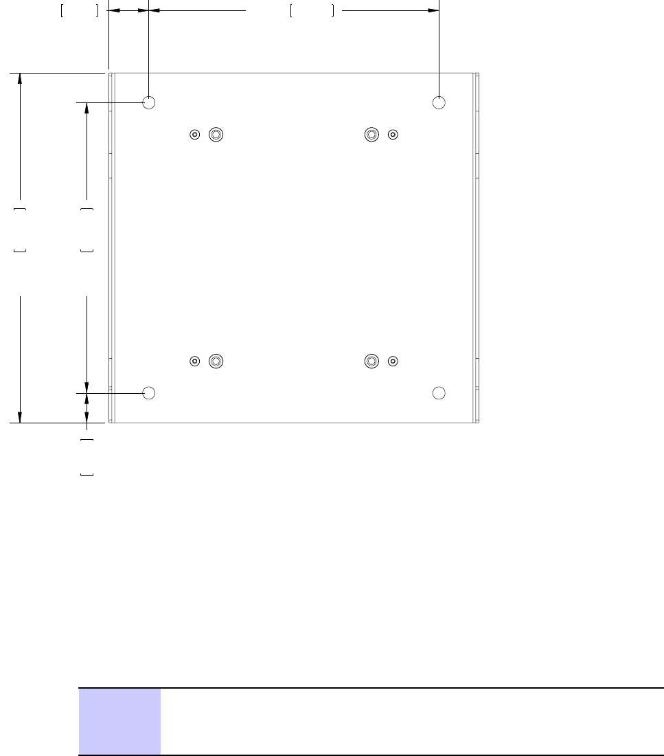
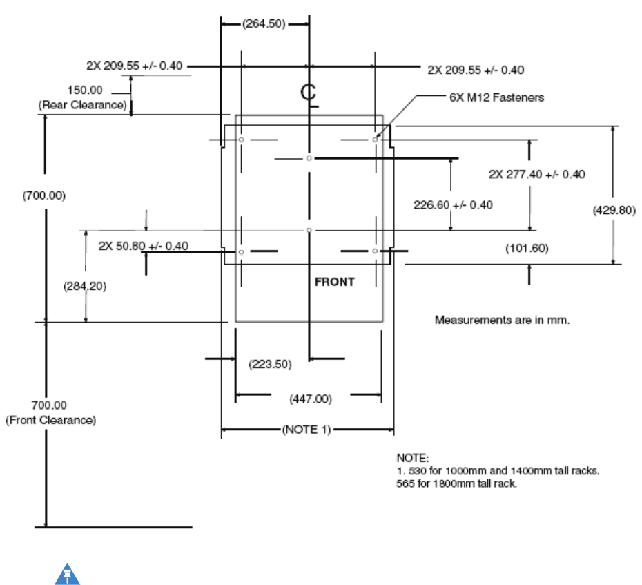
053.21
96
.
313
050.176.62 052.01
53
.
062
1.40835.75 10.250
260.35
Continued

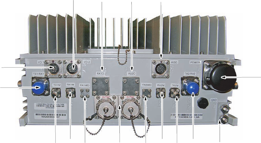
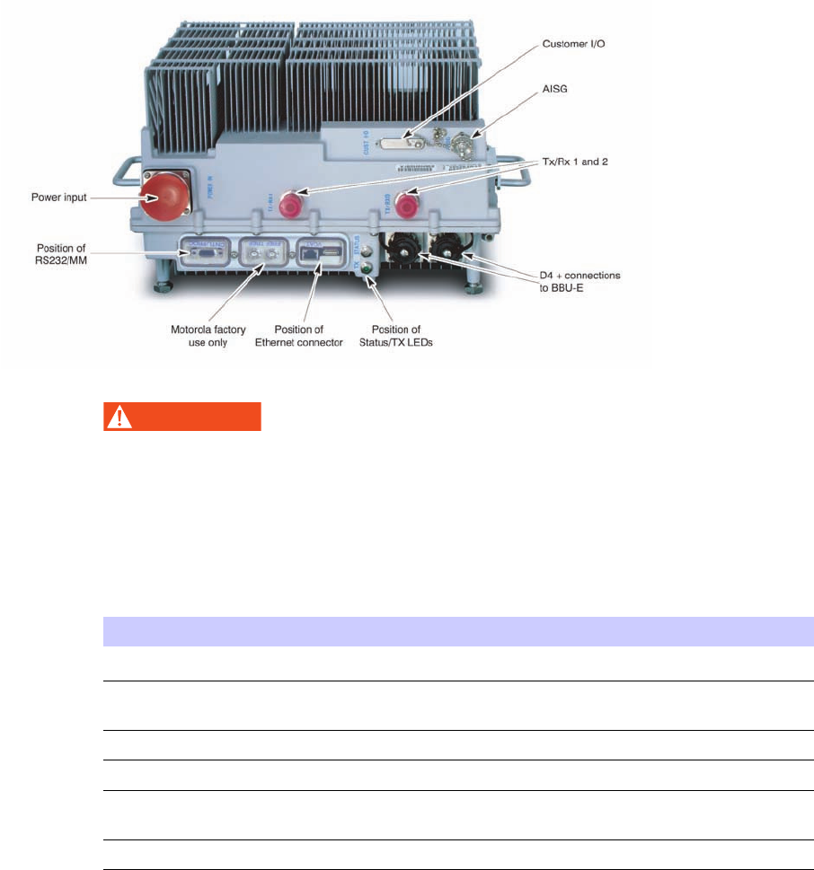
E1_radiohd_frt.eps
TX1M 2x MOLEX
RX1D
TX/RX1
I/O 1
I/O 2
RX2MD
RX1M TX2M
RX2M
RX1D RX2D AISG
TX2/RX2
GND
PWR

■■■■■■■■■■■■■■■■■■■■■■■■■■■■■■■■■■■■■■■■■■■■■■■■■■■■■■■■■■■■■
■
■
■
■

■■■■■■■■■■■■■■■■■■■■■■■■■■■■■■■■■■■■■■■■■■■■■■■■■■■■■■■■■■■■■
■
■
WARNING
WARNING

NOTE
NOTE
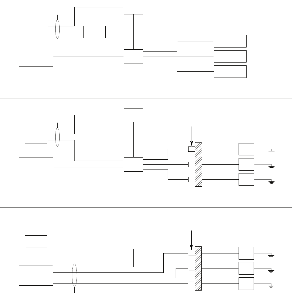
E1_SysPwrCabling1.eps
RACK
MGB Rack
Customer
Supplied
Customer
Supplied
Customer
Power
+27 V
PDU
+27 V Radio Shelf
Radio Shelf
Radio Shelf
BCU
AE
AC
AC
AC
AL
AL
**
** When using a Motorola rack, only the BCU and the frame need to be cabled to the MGB.
When using a non-Motorola rack, all items must be cabled to the MGB.
RRH STYLE 1
MGB
Customer
Supplied
Customer
Supplied
Customer
Power
-48 V
PDU
-48 V
RRH
RRH
RRH
BCU Surge suppressors
and filters *
Building
Entrance/Exit
AE
AK
AK
AK
AB
AB
AB
AL
AL
* Surge suppressors and filters are customer supplied.
MGB = Master Ground Bus
RRH STYLE 2
MGB
Customer
Supplied
Customer
Supplied
Customer
Power
-48 V RRH
RRH
RRH
BCU
Surge suppressors
and filters *
Building
Entrance/Exit
AB
AB
AB
AL
* Surge suppressors and filters are customer supplied.
MGB - Master Ground Bus
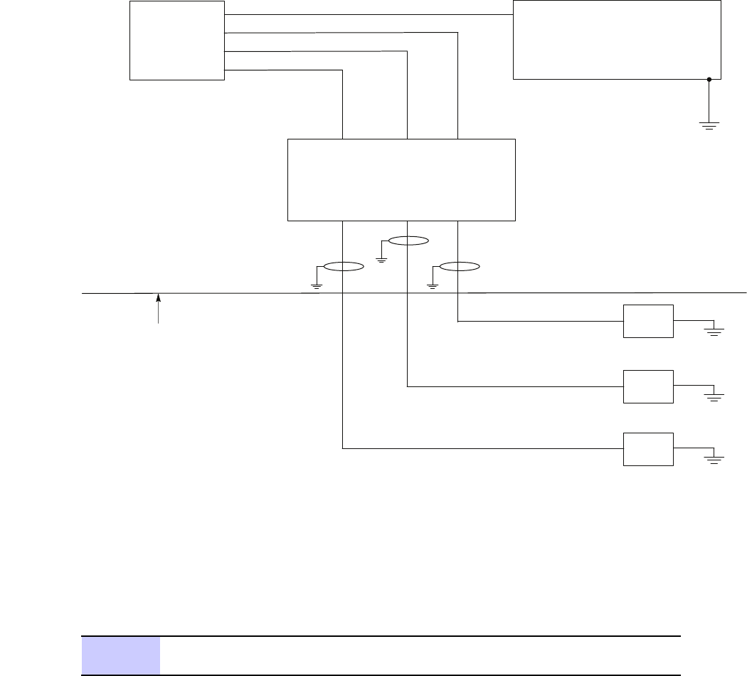
E1_Head_IndoorBCUII_PWR1.eps
Site DC Power
or
Motorola PDU
Transmission Entry Point
(Building Entrance/Exit)
Note: Head is designed to use -48 V dc.
EMI Filter and Surge Protector are customer supplied.
BCU
RRH
RRH
RRH
It is a good practice to ground the
cables at the building entrance using
cable clamps. The power cable
includes a ground braid for this purpose.
Cable clamps are customer supplied
and need to support a 9 mm cable.
Surge Protection and
DC Filters - as required
Continued

Continued

CAUTION
NOTE
NOTE
Continued
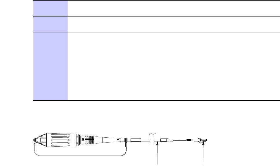
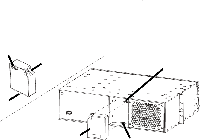
E1_XCR_cable.eps
Grommet
Location
BCU II
Connection
GROMMET
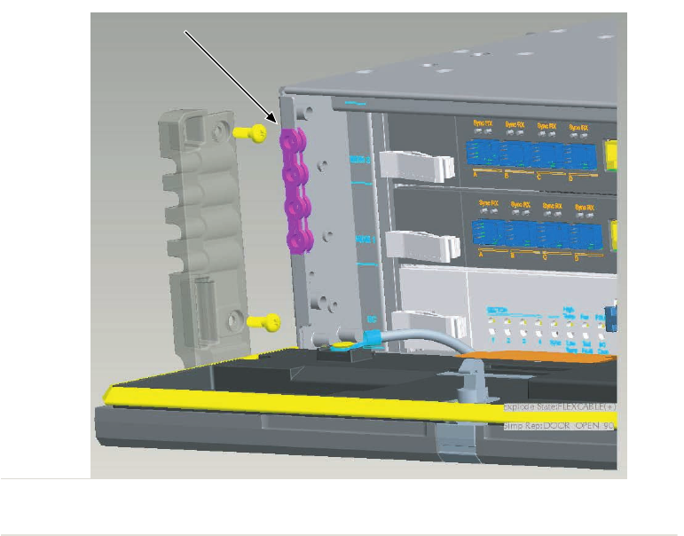
D2_BCUII_Grommet_Location.eps
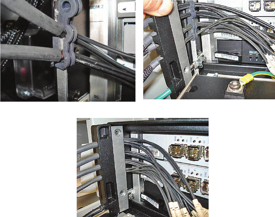
D2_BCUII_FO_Clip_1.eps
View A View B
View C

WARNING
Continued

CAUTION

Continued


■■■■■■■■■■■■■■■■■■■■■■■■■■■■■■■■■■■■■■■■■■■■■■■■■■■■■■■■■■■■■
■
■
NOTE

WARNING
Continued

NOTE
NOTE
NOTE
■■■■■■■■■■■■■■■■■■■■■■■■■■■■■■■■■■■■■■■■■■■■■■■■■■■■■■■■■■■■■
■
■

■■■■■■■■■■■■■■■■■■■■■■■■■■■■■■■■■■■■■■■■■■■■■■■■■■■■■■■■■■■■■
■
■
■
■

■■■■■■■■■■■■■■■■■■■■■■■■■■■■■■■■■■■■■■■■■■■■■■■■■■■■■■■■■■■■■
■
■
NOTE
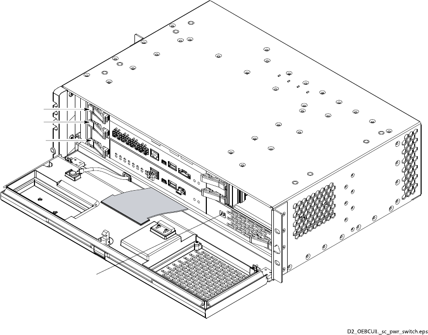
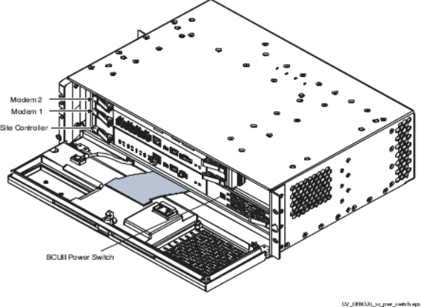
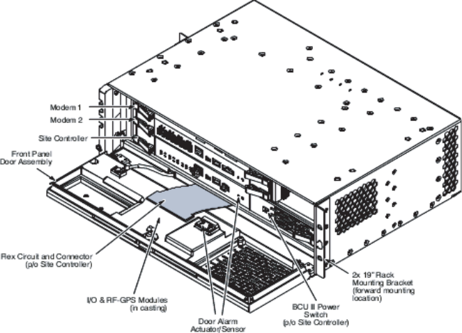
Modem 2
Modem 1
Site Controller
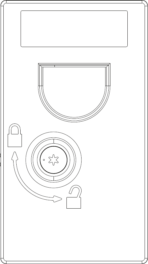
BCUII Power Switch

■■■■■■■■■■■■■■■■■■■■■■■■■■■■■■■■■■■■■■■■■■■■■■■■■■■■■■■■■■■■■
■
■
■
■

■■■■■■■■■■■■■■■■■■■■■■■■■■■■■■■■■■■■■■■■■■■■■■■■■■■■■■■■■■■■■
■
■

■■■■■■■■■■■■■■■■■■■■■■■■■■■■■■■■■■■■■■■■■■■■■■■■■■■■■■■■■■■■■
■
■
CAUTION
Continued

NOTE
Continued

NOTE
■■■■■■■■■■■■■■■■■■■■■■■■■■■■■■■■■■■■■■■■■■■■■■■■■■■■■■■■■■■■■
■
■
CAUTION
CAUTION
NOTE
Continued

CAUTION
DO NOT
CAUTION
Continued

CAUTION
DO NOT

■■■■■■■■■■■■■■■■■■■■■■■■■■■■■■■■■■■■■■■■■■■■■■■■■■■■■■■■■■■■■
■
■
NOTE
Continued

■■■■■■■■■■■■■■■■■■■■■■■■■■■■■■■■■■■■■■■■■■■■■■■■■■■■■■■■■■■■■
■
■

■■■■■■■■■■■■■■■■■■■■■■■■■■■■■■■■■■■■■■■■■■■■■■■■■■■■■■■■■■■■■
■
■
■■■■■■■■■■■■■■■■■■■■■■■■■■■■■■■■■■■■■■■■■■■■■■■■■■■■■■■■■■■■■
■
■
MSO

MSO
ti-cdma-05694.eps
ti-cdma-05694.eps
Mounting Tab Slot
Q-HSO
Q-HSO
Rear View
9-Pin Sub-D Connector
9-Pin Sub-D Connector
Captive Thumbscrew
Mounting Tab
■■■■■■■■■■■■■■■■■■■■■■■■■■■■■■■■■■■■■■■■■■■■■■■■■■■■■■■■■■■■■
■
■

CAUTION
Continued

NOTE
ti-cdma-05694.eps
Fiber Cover
Ground Lug
2X Screws
See Detail A
Detail A
Continued

NOTE
CAUTION
DO NOT
■■■■■■■■■■■■■■■■■■■■■■■■■■■■■■■■■■■■■■■■■■■■■■■■■■■■■■■■■■■■■
■
■

CAUTION
CAUTION
Continued

NOTE

ti-cdma-05694.eps
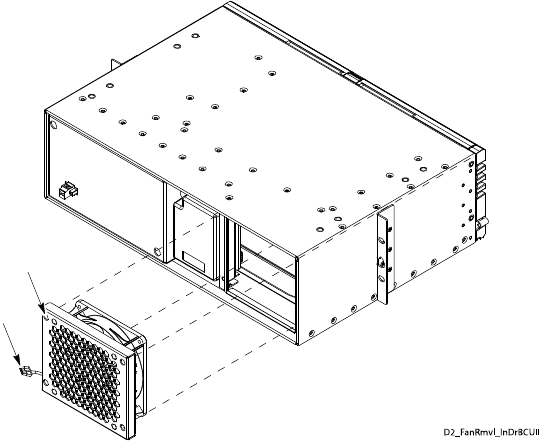
4X Recessed Access Holes for Captive Screws
Fan Tray Power/Control Connector

■■■■■■■■■■■■■■■■■■■■■■■■■■■■■■■■■■■■■■■■■■■■■■■■■■■■■■■■■■■■■
■
■

NOTE
Continued
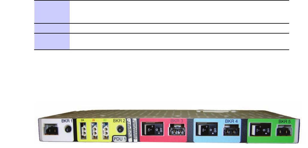
PDU front.eps