Nokia Solutions and Networks T4KJ1 LTE 700 MHz Public Safety Base Station Transceiver User Manual Exhibit 8 Users Manual
Nokia Solutions and Networks LTE 700 MHz Public Safety Base Station Transceiver Exhibit 8 Users Manual
Contents
- 1. Exhibit 8 Users Manual
- 2. Exhibit 8 Users Manual (print)
Exhibit 8 Users Manual

APPLICANT: MOTOROLA
Cellular Networks
FCC ID: IHET4KJ1
Users Manual Exhibit
LTE WBR FDD Frame Based Radio @ 700MHz
FCC Filing – LTE WBR FDD Frame Based Radio @ 700MHz

LTEeNodeBIndoorHardwareInstallation
68P09308A55-6FEB2010
©2009-2010Motorola,Inc.AllRightsReserved

Accuracy
Whilereasonableeffortshavebeenmadetoassuretheaccuracyofthisdocument,Motorola,Inc.assumesno
liabilityresultingfromanyinaccuraciesoromissionsinthisdocument,orfromuseoftheinformationobtained
herein.Motorola,Inc.reservestherighttomakechangestoanyproductsdescribedhereintoimprovereliability ,
function,ordesign,andreservestherighttorevisethisdocumentandtomakechangesfromtimetotimeincontent
hereofwithnoobligationtonotifyanypersonofrevisionsorchanges.Motorola,Inc.doesnotassumeanyliability
arisingoutoftheapplicationoruseofanyproduct,software,orcircuitdescribedherein;neitherdoesitconvey
licenseunderitspatentrightsortherightsofothers.Itispossiblethatthispublicationmaycontainreferencesto,or
informationaboutMotorolaproducts(machinesandprograms),programming,orservicesthatarenotannounced
inyourcountry .SuchreferencesorinformationmustnotbeconstruedtomeanthatMotorolaintendstoannounce
suchMotorolaproducts,programming,orservicesinyourcountry .
Copyrights
Thisdocument,Motorolaproducts,and3rdPartySoftwareproductsdescribedinthisdocumentmayinclude
ordescribecopyrightedMotorolaandother3rdPartysuppliedcomputerprogramsstoredinsemiconductor
memoriesorothermedia.LawsintheUnitedStatesandothercountriespreserveforMotorola,itslicensors,and
other3rdPartysuppliedsoftwarecertainexclusiverightsforcopyrightedmaterial,includingtheexclusiveright
tocopy ,reproduceinanyform,distributeandmakederivativeworksofthecopyrightedmaterial.Accordingly ,
anycopyrightedmaterialofMotorola,itslicensors,orthe3rdPartysoftwaresuppliedmaterialcontainedinthe
Motorolaproductsdescribedinthisdocumentmaynotbecopied,reproduced,reverseengineered,distributed,
mergedormodiedinanymannerwithouttheexpresswrittenpermissionofMotorola.Furthermore,thepurchase
ofMotorolaproductsshallnotbedeemedtogranteitherdirectlyorbyimplication,estoppel,orotherwise,any
licenseunderthecopyrights,patentsorpatentapplicationsofMotorolaorother3rdPartysuppliedsoftware,
exceptforthenormalnon-exclusive,royaltyfreelicensetousethatarisesbyoperationoflawinthesaleofa
product.
Restrictions
Softwareanddocumentationarecopyrightedmaterials.Makingunauthorizedcopiesisprohibitedbylaw.Nopart
ofthesoftwareordocumentationmaybereproduced,transmitted,transcribed,storedinaretrievalsystem,or
translatedintoanylanguageorcomputerlanguage,inanyformorbyanymeans,withoutpriorwrittenpermission
ofMotorola,Inc.
LicenseAgreements
ThesoftwaredescribedinthisdocumentisthepropertyofMotorola,Incanditslicensors.Itisfurnishedbyexpress
licenseagreementonlyandmaybeusedonlyinaccordancewiththetermsofsuchanagreement.
HighRiskMaterials
Components,units,or3rdPartyproductsusedintheproductdescribedhereinareNOTfault-tolerantandareNOT
designed,manufactured,orintendedforuseason-linecontrolequipmentinthefollowinghazardousenvironments
requiringfail-safecontrols:theoperationofNuclearFacilities,AircraftNavigationorAircraftCommunication
Systems,AirTrafcControl,LifeSupport,orWeaponsSystems(HighRiskActivities).Motorolaanditssupplier(s)
specicallydisclaimanyexpressedorimpliedwarrantyoftnessforsuchHighRiskActivities.
Trademarks
MotorolaandtheStylizedMLogoareregisteredintheUSPatent&TrademarkOfce.Allotherproductorservice
namesarethepropertyoftheirrespectiveowners.
TheCEmarkconrmsMotorola,Inc.statementofcompliancewithEUdirectivesapplicabletothisproduct.Copies
oftheDeclarationofComplianceandinstallationinformationinaccordancewiththerequirementsofEN50385can
beobtainedfromthelocalMotorolarepresentativeorbycontactingtheCustomerNetworkResolutionCenter
(CNRC).The24hourtelephonenumbersarelistedathttps://mynetworksupport.motorola.com.SelectCustomer
NetworkResolutionCentercontactinformation.AlternativelyifyoudonothaveaccesstoCNRCorthe
internet,contacttheLocalMotorolaOfce.
FEB2010

Table
of
Contents
Contents
■■■■■■■■■■■■■■■■■■■■■■■■■■■■■■■■■■■■■■■■■■■■■■■■■■■■■■■■■■■■■
■
■
■
■
LTEeNodeBIndoorHardwareInstallation
Revisionhistory.........................................2
Versioninformation.....................................2
Releaseinformation.....................................2
ResolutionofServiceRequests...............................2
Generalinformation.......................................3
Purpose...........................................3
Crossreferences.......................................3
Documentbannerdenitions................................3
Textconventions.......................................4
ContactingMotorola.......................................5
24–hoursupport.......................................5
OrderingdocumentsandCD-ROMs.............................5
Questionsandcomments..................................5
Errors............................................5
Chapter1:Introduction
Overview.............................................1-2
Notaplanningguide.....................................1-2
Followthesiteplan.....................................1-2
Prerequisites.........................................1-2
Systemshippedunassembled................................1-2
ProductDescription.....................................1-3
MajorComponentswithCall-outs................................1-5
Congurationssupported....................................1-7
Chapter2:Sitepreparation
Overview.............................................2-2
Preparingthesiteforequipmentarrival...........................2-2
LTEeNodeBComponentDimensions............................2-4
Framedimensionsandclearances..............................2-5
ElectricalRequirements.....................................2-7
Cabinetvoltage.......................................2-7
DCsupplyequipment,Maincircuitbreaker,andDCinputcable...............2-7
Sitegrounding........................................2-9
EnvironmentRequirements...................................2-10
Operatingtemperaturerange................................2-10
CableRequirements.......................................2-11
eNodeBCableDescriptions(min90Cinsulationrating)...................2-13
ToolsrequiredforinstallingtheeNodeBcomponents......................2-15
68P09308A55-6i
FEB2010
Contents
Chapter3:Frame-basedeNodeBInstallation
Overview.............................................3-2
UnpackingEquipment......................................3-5
Installationoftherack......................................3-6
Rackandgroundcableinstallation.............................3-6
Installingthe+27Vdc(PDU)..................................3-9
Requiredmaterialsandtools.................................3-9
InstallingthePDU......................................3-9
InstallationoftheBCUII.....................................3-14
Requiredmaterialsandtools.................................3-14
BCUIIinstallation......................................3-15
InstallationofRadio/FilterShelf(RFS)andFrameMountedRadioHead............3-19
RFSpowercableinstallation.................................3-22
RFSGroundCableInstallation................................3-23
InstallationoftheGPS......................................3-25
InstallingRFGPSantennaandcable.............................3-25
Optionalequipment.......................................3-28
Quartz-highstabilityoscillator................................3-28
Chapter4:InstallationoftheindoorportionsoftheRe-
moteRFbasedeNodeB
InstallationoftheBCUII.....................................4-2
Requiredmaterialsandtools.................................4-2
BCUIIinstallation......................................4-3
Chapter5:InstallationoftheRRH
InstallingtheRemoteRadioHead................................5-2
Installingthe700MHzRRH.................................5-2
700MHzRRHpolemountconguration...........................5-9
700MHzRRHconnections.................................5-16
Installationof2.1/2.6GHzRRH...............................5-17
2.1/2.6GHzRRHpolemountconguration.........................5-19
2.1/2.6GHzRRH......................................5-21
Chapter6:CablingoftheRRH
Inter-cabling–betweenmajorcomponents...........................6-2
SafetywhenhandlingFiber/PowerSupplyandEarthCables................6-2
RRHgoundconnections...................................6-3
RRHpowerconnections...................................6-3
RRHtoBCUIIinterconnect.................................6-10
InstallingRFcablesfromantennastoRRH.........................6-16
CustomerI/Ocableinstallation...............................6-16
Ethernetcableinstallation..................................6-17
RRHhead–48Vdcpowercablinginstallation..........................6-19
RRH–48VdcpowerwhenusingaBCUII..........................6-19
Circuitbreakerfordcoutputtohead............................6-19
Connecting–48VdcPower.................................6-19
CablingofRRH.........................................6-22
2.1/2.6GHzRRH.......................................6-22
Chapter7:Power-upsequence
PowerUpSequence.......................................7-2
ii68P09308A55-6
FEB2010
Contents
Chapter8:FieldReplaceableUnits
ListofFieldReplaceableUnits(FRUs)..............................8-2
BCUIIFlex4ModemReplacement................................8-3
Objectives..........................................8-3
Preparation.........................................8-3
ReplacementProcedure...................................8-3
BCUIISiteControllerCardReplacement............................8-6
Objectives..........................................8-6
Preparation.........................................8-6
ReplacementProcedure...................................8-6
eNodeFrameBasedRadioReplacement.............................8-10
Objectives..........................................8-10
Preparation.........................................8-10
eNodeBFrameBasedRadioReplacementProcedure....................8-10
Filter/DuplexerReplacement...................................8-12
Objectives..........................................8-12
Preparation.........................................8-12
Filter/DuplexerReplacementProcedure...........................8-12
Radio/FilterShelfFanTrayReplacement............................8-14
Objective...........................................8-14
Preparation.........................................8-14
Radio/FilterShelfFanTrayreplacementprocedure.....................8-14
Q-HSO(QuartzHighStabilityOscillator)Replacement.....................8-17
Q-HSO(QuartzHighStabilityOscillator)Replacement...................8-17
Preparation.........................................8-17
Requiredtools........................................8-17
Torquerequirements.....................................8-18
Requireditem........................................8-18
Q-HSOreplacementprocedure...............................8-18
Referencediagram......................................8-18
BCUIIcardcageassemblyreplacementprocedures.......................8-20
Objectives..........................................8-20
Introduction.........................................8-20
Preparation.........................................8-20
BCUIIFanTrayReplacement..................................8-25
Objectives..........................................8-25
Introduction.........................................8-25
Preparation.........................................8-25
ReplacementProcedure...................................8-26
eNodeBPDUReplacement....................................8-30
Objective...........................................8-30
Preparation.........................................8-30
eNodeBPDUreplacementprocedure............................8-31
68P09308A55-6iii
FEB2010

List
of
Figures
ListofFigures
■■■■■■■■■■■■■■■■■■■■■■■■■■■■■■■■■■■■■■■■■■■■■■■■■■■■■■■■■■■■■
■
■
■
■
Figure1-1:Majorcomponents..................................1-5
Figure1-2:RadioFrameShelf..................................1-6
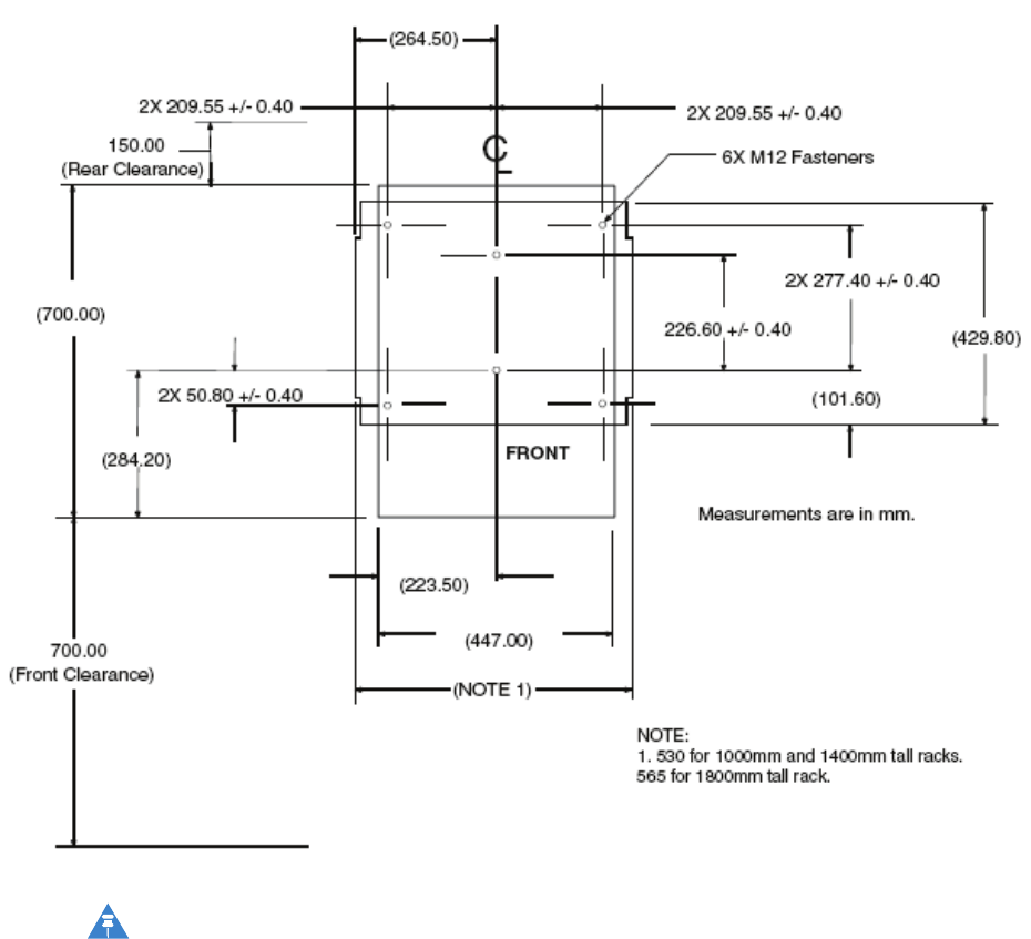
Figure2-1:Framedimensionsandclearances..........................2-6
Figure2-2:SystemPowerCabling................................2-12
Figure2-3:SystemDataCabling................................2-13
Figure3-1:Indoorsystem....................................3-3
Figure3-2:RadioFrameShelf..................................3-4
Figure3-3:LocationofgroundterminalsonaMotorolarack..................3-8
Figure3-4:PDUpowerconnection...............................3-12
Figure3-5:PDUFront......................................3-13
Figure3-6:BCUIIphysicaldesign................................3-14
Figure3-7:CablingPowerto+27VdcBCUII..........................3-16
Figure3-8:BCUIIGrounding..................................3-18
Figure3-9:Radio/FilterShelf..................................3-19
Figure3-10:InstallingDuplexer.................................3-20
Figure3-11:Tyingpowercablestothecabletiebrackets....................3-23
Figure3-12:RFSgroundcableconnection...........................3-24
Figure3-13:RFGPSinstallationandcomponentsdiagram....................3-27
Figure3-14:BCUIIQ-HSOunit.................................3-28
Figure4-1:BCUIIphysicaldesign................................4-2
Figure4-2:CablingPowerto–48VdcBCUII...........................4-4
Figure4-3:BCUIIGrounding..................................4-5
Figure5-1:700MHzRRHconnections.............................5-17
Figure5-2:LTE2.1/2.6GHzRRHWallMountBracketMountingHoleLocations........5-19
Figure5-3:LTE2.1/2.6GHzRRHMountingBracket......................5-21
Figure5-4:2.1GHzRRH....................................5-22
Figure6-1:SystemPowerCabling................................6-6
Figure6-2:2.6GHzRRHconnections..............................6-7
Figure6-3:RRHpowercabling.................................6-8
Figure6-4:FiberCable.....................................6-11
Figure6-5:BCUIIFiberOpticCableGrommetLocation.....................6-12
Figure6-6:FiberOpticCableBrackets.............................6-13
Figure6-7:FiberOpticCableClipInstallation..........................6-14
Figure7-1:BCUIIPowerSwitch.................................7-3
Figure8-1:RFSfantrayinunlockedposition..........................8-15
Figure8-2:RFSfantrayinlockedposition...........................8-16
Figure8-3:Q-HSOremovalandinstallation...........................8-19
Figure8-4:BCUIIFiberCover..................................8-23
Figure8-5:Fantrayremovalandinstallation..........................8-29
Figure8-6:PDU.........................................8-32
68P09308A55-6v
FEB2010

List
of
Tables
ListofTables
■■■■■■■■■■■■■■■■■■■■■■■■■■■■■■■■■■■■■■■■■■■■■■■■■■■■■■■■■■■■■
■
■
■
■
Table1-1:PDU..........................................1-4
Table1-2:CongurationsSupported...............................1-7
Table2-1:LTEeNodeBcomponentdimensions.........................2-4
Table2-2:WireAWG(min90Cinsulationrating)andcircuitbreakersizingfor+27Vdcframe
systems.............................................2-7
Table2-3:WireAWG(min90Cinsulationrating)andcircuitbreakersizingfor–48Vdcremote
RFbasedeNodeB(forsystemsusingtheMotorola-48VPDU).................2-8
Table2-4:eNodeBCableDescriptions..............................2-13
Table3-1:Frame-basedeNodeBcableconnectionstoPDUbreakers..............3-13
Table3-2:Lugcriteria......................................3-13
Table5-1:LEDcongurations..................................5-17
Table6-1:Fibercablesrouting.................................6-15
Table6-2:Lugcriteria......................................6-21
Table8-1:eNodeBFRUInformation...............................8-2
68P09308A55-6vii
FEB2010

About
This
Manual
LTEeNodeBIndoorHardwareInstallation
■■■■■■■■■■■■■■■■■■■■■■■■■■■■■■■■■■■■■■■■■■■■■■■■■■■■■■■■■■■■■
■
■
■
■
Whatiscoveredinthismanual?
ThisdocumentprovidesthephysicalhardwareinstallationproceduresfortheLTEframeand
radiounits.Itisnotasystemorsiteplanningdocument.
68P09308A55-61
FEB2010

Revisionhistory
Revisionhistory
■■■■■■■■■■■■■■■■■■■■■■■■■■■■■■■■■■■■■■■■■■■■■■■■■■■■■■■■■■■■■
■
■
Thefollowingsectionsshowtherevisionstatusofthisdocument.
Versioninformation
Thefollowingtabledescribesthechangesmadetothisdocument:
VersionDateofissueDescription
1OCT2009Initialrelease.
2NOV2009RemovedFCCRequirements.UpdatedChapter6.
AddedseveralguresandsplitProcedure6–2into
twoseparateprocedures:connectingtotheBCUII
andconnectingtotheRRH.
3NOV2009AddedPDUConnectiongureinChapter3.
4DEC2009AddedRRHPowercabledetail.
CorrectedFTRissues.
5FEB2010UpdatedeNodeBFRUInformation.
6FEB2010Updatesfromreviewcomments.
Releaseinformation
Thisistherstreleaseofthisdocument.
ResolutionofServiceRequests
ThefollowingServiceRequestsareresolvedinthisdocument:
Service
RequestCMBPNumberDescription
NANAInitialrelease
268P09308A55-6
FEB2010

Generalinformation
Generalinformation
■■■■■■■■■■■■■■■■■■■■■■■■■■■■■■■■■■■■■■■■■■■■■■■■■■■■■■■■■■■■■
■
■
Purpose
Motoroladocumentsprovidetheinformationtooperate,install,andmaintainMotorola
equipment.Itisrecommendedthatallpersonnelengagedinsuchactivitiesbeproperlytrained
byMotorola.
Motoroladisclaimsallliabilitywhatsoever,impliedorexpressed,foranyriskofdamage,lossor
reductioninsystemperformancearisingdirectlyorindirectlyoutofthefailureofthecustomer ,
oranyoneactingonthecustomer'sbehalf,toabidebytheinstructions,systemparameters,
orrecommendationsmadeinthisdocument.
Thesedocumentsarenotintendedtoreplacethesystemandequipmenttrainingofferedby
Motorola.Theycanbeusedtosupplementandenhancetheknowledgegainedthroughsuch
training.
NOTE
IfthisdocumentwasobtainedwhenattendingaMotorolatrainingcourse,itisnot
updatedoramendedbyMotorola.ItisintendedforTRAININGPURPOSESONLY .Ifit
wassuppliedundernormaloperationalcircumstances,tosupportamajorsoftware
release,thenMotorolaautomaticallysuppliescorrectionsandpostsontheMotorola
customerwebsite.
Crossreferences
Referencesmadetoexternalpublicationsareshowninitalics.Othercrossreferences,
emphasizedinbluetextinelectronicversions,areactivelinkstothereferences.
Thisdocumentisdividedintonumberedchaptersthataredividedintosections.Sectionsare
notnumbered,butareindividuallynamedatthetopofeachpage,andarelistedinthetableof
contents.
Documentbannerdenitions
Abannerindicatesthatsomeinformationcontainedinthedocumentisnotyetapprovedfor
generalcustomeruse.Abannerisoversizedtextonthebottomofthepage,forexample,
PRELIMINARY—UNDERDEVELOPMENT
68P09308A55-63
FEB2010

Textconventions
Textconventions
ThefollowingconventionsareusedinMotoroladocumentstorepresentkeyboardinputtext,
screenoutputtext,andspecialkeysequences.
Input
Characterstypedinatthekeyboardareshownlikethissentence.
Itemsofinterestwithinacommandappearlikethissentence.
Output
Messages,prompts,filelistings,directories,utilities,andenvironmental
variablesthatappearonthescreenareshownlikethissentence.
Itemsofinterestwithinascreendisplayappearlikethissentence.
Specialkeysequences
Specialkeysequencesarerepresentedasfollows:
CTRL-corCTRL+CPresstheCtrlandCkeysatthesametime.
CTRL-SHIFT-cor
CTRL+SHIFT+C
PresstheCtrl,Shift,andCkeysatthesametime.
ALT-forALT+FPresstheAltandFkeysatthesametime.
ALT+SHIFT+F11PresstheAlt,ShiftandF11keysatthesametime.
¦Pressthepipesymbolkey .
RETURNorENTERPresstheReturnorEnterkey .
468P09308A55-6
FEB2010
ContactingMotorola
ContactingMotorola
■■■■■■■■■■■■■■■■■■■■■■■■■■■■■■■■■■■■■■■■■■■■■■■■■■■■■■■■■■■■■
■
■
Motorolaappreciatesfeedbackfromtheusersofourdocuments.
24–hoursupport
Ifyouhaveproblemsregardingtheoperationofyourequipment,contacttheCustomerNetwork
ResolutionCenter(CNRC)forimmediateassistance.The24–hourtelephonenumbersarelisted
athttps://mynetworksupport.motorola.com.SelectCustomerNetworkResolutionCenter
contactinformation.AlternativelyifyoudonothaveaccesstoCNRCortheinternet,contact
theLocalMotorolaOfce.
OrderingdocumentsandCD-ROMs
Withinternetaccessavailable,toview ,download,ororderdocuments(originalorrevised),visit
theMotorolacustomerwebpageathttps://mynetworksupport.motorola.com,orcontactyour
Motorolaaccountrepresentative.
Withoutinternetaccessavailable,orderhard-copydocumentsorCD-ROMsfromyourMotorola
LocalOfceorRepresentative.
IfMotorolachangesthecontentofadocumentaftertheoriginalprintingdate,Motorola
publishesanewversionwiththesamepartnumberbutadifferentrevisioncharacter.
Questionsandcomments
Sendquestionsandcommentsregardinguserdocumentationtotheemailaddress:
mydocs@motorola.com.
Errors
Toreportadocumentationerror,calltheCNRC(CustomerNetworkResolutionCenter)and
providethefollowinginformationtoenableCNRCtoopenanSR(ServiceRequest):
•Thedocumenttype
•Thedocumenttitle,partnumber,andrevisioncharacter
•Thepagenumberwiththeerror
•Adetaileddescriptionoftheerrorandifpossibletheproposedsolution
68P09308A55-65
FEB2010
Errors
668P09308A55-6
FEB2010

Chapter
1
Introduction
■■■■■■■■■■■■■■■■■■■■■■■■■■■■■■■■■■■■■■■■■■■■■■■■■■■■■■■■■■■■■
■
■
■
■
68P09308A55-61-1
FEB2010
OverviewChapter1:Introduction
Overview
■■■■■■■■■■■■■■■■■■■■■■■■■■■■■■■■■■■■■■■■■■■■■■■■■■■■■■■■■■■■■
■
■
Thisdocumentprovidesinformationpertainingtothehardwareandcablinginstallationforthe
frame-basedeNodeBandRemoteRF-basedeNodeBversionsoftheMotorolaLTEeNodeB
Hardware.Thespecichardwareunitsdiscussedinthismanualareasfollows:
•PowerDistributionUnit(PDU)
•BCUII
•RadioHeads
•GPS
Notaplanningguide
Donotusethismanualasaplanningguide.Completeallsite-specicplansandinformation
beforestartingtheinstallation.Thesite-specicinformationdeterminestheexactplacement
oftheframes,FRUs,andcables.
Followthesiteplan
Itemsandcablesarecoveredintheinstallationprocedurethatmaynotapplytoaspecicsite
conguration.Refertothesiteplantodeterminewhichitemsandcablesareinstalled.Skip
overthoseproceduresforitemsandcablesthatarenotrequired.
Prerequisites
Thefollowingarethethreemajorprerequisites:
•AStructuralEngineerhasspeciedtheprocedure,tools,andequipmenttomountthe
frametotheoor.
•Allthesitepreparations(includingpower)arecompletedaccordingtothesiteplan.
•Allsiteplanningandcongurationinformationisavailable.
Systemshippedunassembled
TheeNodeBisshippedunassembledinseveralcartons/boxes.TheeNodeBisassembledat
thecustomer’ssite.
1-268P09308A55-6
FEB2010
LTEeNodeBIndoorHardwareInstallationProductDescription
ProductDescription
TheeNodeBversionsdescribedinthismanualprovideairinterfacesupporttouserequipment
whilealsoterminatingsignalingandbearerpacketsandcommunicatingwithothereNodeB
peersinthenetwork.TheeNodeBsupportsFDDinarangeoffrequencies,including:700MHz,
2.1GHz,and2.6GHz.TheeNodeBhastwocongurations.Therstisaframe-basedeNodeB
whichconsistsofastandard19-inchrack,BCUII,RadioFilterShelf(containsframeradioand
duplexer),anda+27VPDU.ThesecondisaRemoteRF-basedeNodeBwhichconsistsofa
standard19-inchrack,BCUII,RemoteRadioHeads,andanoptional–48VPDU.
Racks
Motorolaprovidesracks,designedtomeetseismiczone4loading,inthreesizes:
•Indoor19-inchrack(925mm)
•Indoor19-inchrack(1325mm)
•Indoor19-inchrack(1769mm)
BaseControlUnitII
TheBCUIIisasmall,self-containedrackmountableunit.Itcanhaveoneortwomodems,a
fan,aPSU,andanoptionalQ-HSO.
RemoteRadioHead
TheLTEeNodeBRemoteRadioHead(RRH)isafrequency-dependentRadioResourceUnit
(RRU)thatcanbemountedremotelyfromtheindoorframe.Itisastandalonenaturally
convectioncooledoutdoorproductthatcanalsobeinstalledindoors.
RadioFilterShelf
Theradioltershelfisarackmountableunit.Itincludesafanassembly ,andalter/duplexer .
Also,theLTEeNodeBframebasedradio(FBR)ismountedintheradioltershelf.
FrameBasedRadio
TheLTEeNodeBframebasedradio(FBR)isafrequency-dependentradioresourceunitthatis
mountedintheradioltershelf.Itrequiresforcedconvectioncoolingandisinstalledindoors.
68P09308A55-61-3
FEB2010

ProductDescriptionChapter1:Introduction
PowerDistributionUnit
ThePDUisavailableina+27Vdcversionforframe-basedeNodeBora–48Vdcversionfor
RemoteRF-basedeNodeB.ThecustomercanchoosetoprovidetheirownPDUfunctionfor
theRemoteRF-basedeNodeBcongurations.
Table1-1PDU
PowerAmperageSupports
+27Vdc175Ainputfromcustomer
–48Vdc100Ainputfromcustomer
3Radiosvia3x40Abreakers
1xBCUIIvia1x30Abreaker
3xAuxvia1x15Abreaker
ManualOrder
Chapter1—IntroductionThischapterprovidesscopeofthemanual,anoverviewof
manualchapters,andidenticationoftheeNodeBmajorcomponents.Alsodescribedarethe
differentcongurationsthataresupportedandhowallthecomponentsinteract.
Chapter2—SitePreparationThischapterprovidestheproceduresandinformationto
verifythatthesiteisreadytohavetheframesandotherequipmentinstalled.
Chapter3—Frame-basedeNodeBInstallationThischapterprovidesinformation
forunpacking,installing,andgroundingtherack,andinstallingmajorcomponentsofthe
frame-basedeNodeB.
Chapter4—InstallationoftheindoorportionsoftheRemoteRFbased
eNodeBThischapterprovidesinformationforinstallingtheBCUII.
Chapter5—InstallationoftheRRHThischapterprovidesinformationforinstallingthe
RemoteRadioHead(RRH).
Chapter6—CablingoftheRRHThischapterprovidescablinginstructionsfortheRRH
andinterconnectfromtheindoorrackmountedequipmenttothebuildingI/Opointforthe
RemoteRFBasedeNodeB.
Chapter7—Power-upsequenceThischapterprovidesthepower-upsequenceforthe
eNodeB.
Chapter8—FieldReplaceableUnitsThischapterprovidesproceduresforremoval
andreplacementofFRUs.
1-468P09308A55-6
FEB2010
LTEeNodeBIndoorHardwareInstallationMajorComponentswithCall-outs
MajorComponentswithCall-outs
■■■■■■■■■■■■■■■■■■■■■■■■■■■■■■■■■■■■■■■■■■■■■■■■■■■■■■■■■■■■■
■
■
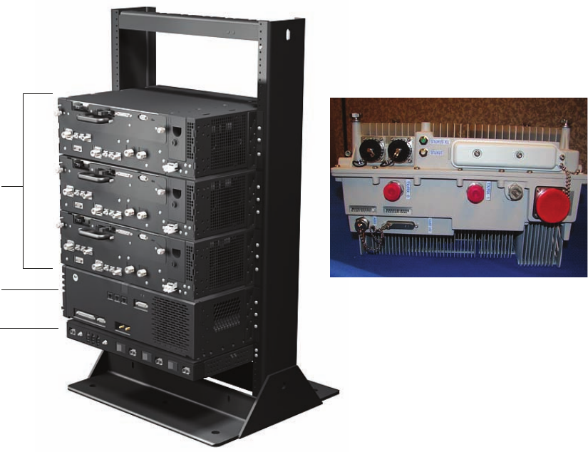
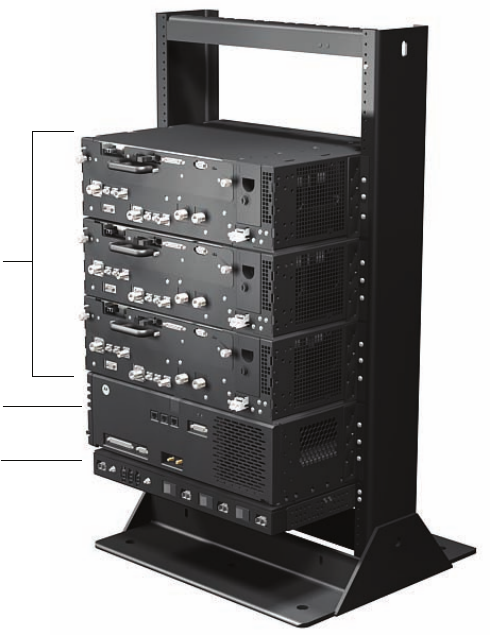
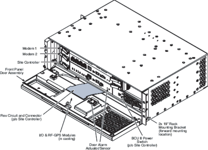
Figure1-1Majorcomponents
E1_majorcomponents_eNodeB.eps
3X
Radio Shelves
Remote Radio Head
BCUII
PDU
68P09308A55-61-5
FEB2010

MajorComponentswithCall-outsChapter1:Introduction
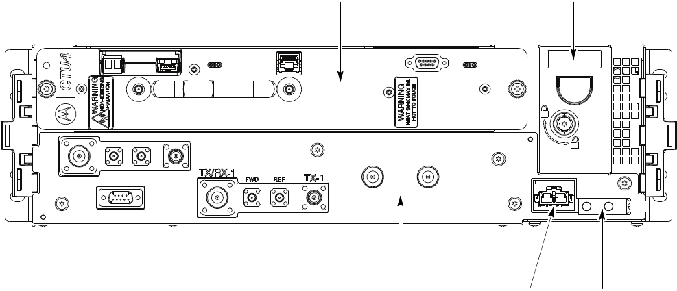
Figure1-2RadioFrameShelf
Radio Fan Tray
Ground Lug
Power InputRF Filter
(behind front panel)
1-668P09308A55-6
FEB2010

LTEeNodeBIndoorHardwareInstallationCongurationssupported
Congurationssupported
■■■■■■■■■■■■■■■■■■■■■■■■■■■■■■■■■■■■■■■■■■■■■■■■■■■■■■■■■■■■■
■
■
Thefollowingcongurationsaresupported:
Table1-2CongurationsSupported
RadioBCUPower
SupplyFrequencyBandCongurationType
FrameMountedBCUII+27Vdc700MHzFrame-basedeNodeB
RemoteRadioHeadBCUII–48Vdc2.1GHzRemoteRF-based
eNodeB
RemoteRadioHeadBCUII–48Vdc2.6GHzRemoteRF-based
eNodeB
RemoteRadioHeadBCUII–48Vdc700MHzRemoteRF-based
eNodeB
68P09308A55-61-7
FEB2010
CongurationssupportedChapter1:Introduction
1-868P09308A55-6
FEB2010

Chapter
2
Sitepreparation
■■■■■■■■■■■■■■■■■■■■■■■■■■■■■■■■■■■■■■■■■■■■■■■■■■■■■■■■■■■■■
■
■
■
■
68P09308A55-62-1
FEB2010

OverviewChapter2:Sitepreparation
Overview
■■■■■■■■■■■■■■■■■■■■■■■■■■■■■■■■■■■■■■■■■■■■■■■■■■■■■■■■■■■■■
■
■
TheSitepreparationsectionprovidestheproceduresandinformationtoverifythatthesiteis
readytohavetheframesandotherequipmentinstalled.
Preparingthesiteforequipmentarrival
Basedonthesitecharacteristics,executethestepsthatapplytothesite.
Preparingtheoutdoorsitefortheequipment
Adetailedlayoutofthesiteisprovidedwiththesite-specicdocumentation.Beforeinstalling
thehardware,comparetheinformationpresentedheretothesite-specicdocumentationlayout
andverifythefollowingwiththesitemanager:
•Siteisclean.
•Site-specicdocumentationcoveringallsite-dependentinstallationinformationis
available.
•Theinstallationareahasrestrictedaccess.Equipmentismeanttobeinstalledand
operatedinarestrictedaccesslocation.
•Allbuilding/siteACorDCpowercablinghasbeeninstalled.
•Thescreen(outershield)oftheRFantennacoaxialcablemustbeconnectedtoearth
(grounded)attheentrancetothebuilding.Connectinggroundshouldbedonein
accordancewithapplicablenationalelectricalinstallationcodes(Section820.93ofthe
NationalElectricalCode,ANSI/NFPA70.
•Thisequipmentshallbeconnecteddirectlytothedcsupplysystemearthingelectrode
conductorortoabondingjumperfromanearthingterminalbarorbustowhichthedc
supplysystemearthingelectrodeconductorisconnected.
Thisequipmentshallbeconnecteddirectlytothedcsupplysystemearthingelectrode
conductorortoabondingjumperfromanearthingterminalbarorbustowhichthe
dcsupplysystemearthingelectrodeconductorisconnected.
Thisequipmentshallbelocatedinthesameimmediatearea(suchasadjacent
cabinets)asanyotherequipmentthathasaconnectionbetweentheearthed
conductorofthesamedcsupplycircuitandtheearthingconductor,andalsothepoint
ofearthingofthedcsystem.Thedcsystemshallnotbeearthedelsewhere.
Thedcsupplysourceshallbelocatedwithinthesamepremisesasthisequipment.
Switchingordisconnectingdevicesshallnotbeintheearthedcircuitconductor
betweenthedcsourceandthepointofconnectionoftheearthingelectrodeconductor.
•VerifythattheMasterGroundBarisconnectedtoasolidearthground.Connectingthe
MasterGroundBarisrequiredtoensureprotectionfromhazardousvoltagesbyproviding
ahighintegrityprotectiveearthingcircuitwhentheframeislatergroundedtotheMaster
GroundBar.
2-268P09308A55-6
FEB2010

LTEeNodeBIndoorHardwareInstallationPreparingthesiteforequipmentarrival
•Thesitecanmaintaintheoperatingtemperaturerange.
•ThebuildingmeetsthevoltageandamperagerequirementsshowninDCsupply
equipment,Maincircuitbreaker,andDCinputcableonpage2-7.
•Thesitecanmeetthechassisdimensions(asshowninLTEeNodeBComponentDimensions
onpage2-4)andnotviolateanyoftherequiredclearances(asshowninFigure2-1).
•TheDCsupplyequipment,Maincircuitbreaker,andDCinputcablecalledoutinTable2-2
fortheLTEframeDCinputareeitherinstalledoravailabletobeinstalled.
•ThemountinglocationcansupporttheweightoftheLTEframeasstatedinTable2-1.
•TocomplywithUL/60950-1secondeditionsafetyrequirements,cablesconnectedtoAISG
andCustomerI/Omustbenomorethan42meters(140feet)andtheframeground
conductorsizemustbeaminimumof6AWG.
Procedure2-1Preparingtheoutdoorsitefortheequipment
Locatethedemarcationblocksforexternalutilities.
1
VerifythattheyareshownontheSiteEngineeringdocumentsanddetermine
therequiredcableroutingbacktotheequipmentframes.
2Verifythefollowing:
•Availabilityofappropriateelectricalgroundconnectionsforthe
equipment.
•Compliancewithanysiteengineeringdocumentationandspecications.
•DCpowerisavailableandmeetsthesitedocumentationspecications.
•Poleand/orwallmountingstructuresareadequate.Ensurethata
qualiedstructuralengineerveriestheRRHwallorpolestructureand
wall-mountorpole-mountinstallationfortheweightoftheinstallation
underadverseconditionsintheinstallationarea.
•Outdoorcablerunsareinstalledandmeetlocalbuildingcodes.
•Customerinputterminationtiepointsareavailable.
•Availabilityoflightingandpowerforinstallation.
Preparingtheindoorsitefortheequipment
Performthefollowingsteps:
Procedure2-2Preparingtheindoorsitefortheequipment
Locatethedemarcationblocksforinternalutilities.
1
Continued
68P09308A55-62-3
FEB2010

LTEeNodeBComponentDimensionsChapter2:Sitepreparation
Procedure2-2Preparingtheindoorsitefortheequipment(Continued)
VerifythattheyareshownontheSiteEngineeringdocuments,anddetermine
therequiredcableroutingbacktotheequipmentframes.
2Verifythefollowing:
•Availabilityoflightingandpowerforinstallation.
•Availabilityofappropriateelectricalgroundconnectionsforthe
equipment.
•Accessto,androutingof;inputpower,RFoutput,andgeneral
interconnectioncablingspace.
•DCpowerisavailableandmeetsthesitedocumentationspecications.
•LevelsurfaceandoorsupporttohandletheweightoftheeNodeB
equipment,frame,andcabling.
•Compliancewithanysiteengineeringdocumentationandspecications.
LTEeNodeBComponentDimensions
Table2-1showscomponentdimensionsforbothFrame-basedeNodeBandRemoteRF-based
eNodeBcongurations.
Table2-1LTEeNodeBcomponentdimensions
ItemDescriptionWidth
(mm)
Depth
(mm)
Height
(mm)
Weight
(inlbs)
Mass
(inKg)
Height
(Rack
units)
Quantity
FrameRemote
STHN414619"Rack53043092566.1430.0018
STHN412119"Rack530430132577.1635.0027
STHN412019"Rack5654301769125.6657.0037
EitherFrameor
Remote
STLN6905Power
Distribution
Unit-+27V
dc
485295448.824.0011—
STLN6906Power
Distribution
Unit-–48V
485295448.824.001—1
SG1756BCUII48533013217.608.00311
STLN6903Radio/Duplexer
Shelf
48533013217.648.0031to3—
Continued
2-468P09308A55-6
FEB2010

LTEeNodeBIndoorHardwareInstallationFramedimensionsandclearances
Table2-1LTEeNodeBcomponentdimensions(Continued)
ItemDescriptionWidth
(mm)
Depth
(mm)
Height
(mm)
Weight
(inlbs)
Mass
(inKg)
Height
(Rack
units)
Quantity
STFF4046DualDuplexer
(UpperC
Band)
2152906311.025.00—1to3—
STWF4000LTEIndoor
Radio(Upper
CBand)
3563056014.336.50—1to3—
2.6GHzRRH3251744094118.8—1to3
2.1GHzRRH3251894094319.8—1to3
700MHzRRH3462103444018.01to3
NOTE
Height,Width,Depthdimensionsdonotincludeconnectorsorcablesthatmaybe
attached.Thesedimensionsalsodonotincludetheremovalhandlesorthehinge.
Framedimensionsandclearances
Figure2-1showsthefootprintoftherack.
68P09308A55-62-5
FEB2010
FramedimensionsandclearancesChapter2:Sitepreparation
Figure2-1Framedimensionsandclearances
NOTE
Aninsulatingpadisattachedtothebaseoftheracktoelectricallyisolatetherack
fromtheoor.
2-668P09308A55-6
FEB2010

LTEeNodeBIndoorHardwareInstallationElectricalRequirements
ElectricalRequirements
■■■■■■■■■■■■■■■■■■■■■■■■■■■■■■■■■■■■■■■■■■■■■■■■■■■■■■■■■■■■■
■
■
Cabinetvoltage
Therearetwobasicpowersystemtypes:
•RemoteRF-basedeNodeB:–48VdcRRH700MHz,2.1GHz,2.6GHz—forthistype,the
customercanusetheoptional–48VdcPDUfromMotorolaortheirowncircuitbreakers.
•Frame-basedeNodeB:+27Vdcframeradio700MHz—forthistype,the+27VdcPDU,
frameradios,andBCUIIareallco-locatedinthesamerack.
DCsupplyequipment,Maincircuitbreaker,andDCinputcable
TheDCsupplyequipment,maincircuitbreaker,andDCinputcablesaredeterminedbythe
sitecharacteristics.
Table2-2WireAWG(min90Cinsulationrating)andcircuitbreakersizingfor+27V
dcframesystems
LTEFDDNumberof
RadiosBreakersize(A)Wiresize
(AWG)
Maximumcable
length(m)
LTEFrame31753/0AWG16
LTEFrame21753/0AWG20
LTEFrame21502/0AWG16
LTEFrame21251/0AWG13
LTEFrame11753/0AWG29
LTEFrame11502/0AWG23
LTEFrame11251/0AWG18
LTEFrame11001AWG14
LTEFrame1902AWG11
68P09308A55-62-7
FEB2010

DCsupplyequipment,Maincircuitbreaker ,andDCinputcableChapter2:Sitepreparation
Table2-3WireAWG(min90Cinsulationrating)andcircuitbreakersizingfor–48V
dcremoteRFbasedeNodeB(forsystemsusingtheMotorola-48VPDU)
LTEFDDNumberof
Radios
Breaker
size(A)Wiresize(AWG)Maximumcable
length(m)
LTERRH31753/0AWG69
LTERRH31502/0AWG55
LTERRH31502/0AWG55
LTERRH31251/0AWG44
LTERRH31001AWG35
LTERRH3902AWG27
LTERRH3803AWG22
LTERRH21753/0AWG89
LTERRH21502/0AWG70
LTERRH21251/0AWG56
LTERRH21001AWG44
LTERRH2902AWG35
LTERRH2803AWG28
LTERRH2704AWG22
LTERRH11753/0AWG124
LTERRH11502/0AWG98
LTERRH11251/0AWG78
LTERRH11001AWG62
LTERRH1902AWG49
LTERRH1803AWG39
LTERRH1704AWG31
2-868P09308A55-6
FEB2010
LTEeNodeBIndoorHardwareInstallationSitegrounding
WireAWG(min90Cinsulationrating)andcircuitbreakersizingfor–48
VDCRRHsystemswithoutPDUoption(customer-providedPDUfunction)
ForBCUIIpowereddirectlyfromthe–48Vdcbranchcircuit,wherethePDUisoptional:
•BCUIIDCbranchcircuitprotection:Singlepole20Aratedcircuitbreakerfornominal
–48Vdc
•BCUIIDCcable:Customer-suppliedDCpowercable,VW-1#8–#10AWG,10m(32.8
feet),ULtemperaturerating105°C(167°F).
ForRRHpowereddirectlyfromthe–48Vdcbranchcircuit,wherethePDUisoptional:
•RRHDCbranchcircuitprotection:Singlepole30Aratedcircuitbreakerfornominal
–48Vdc.
•DCcable#1(branchcircuitbreakertobuildingI/Opoint):Customer-suppliedDCpower
cable,VW-1#8,10m(32.8feet)orless,ULtemperaturerating105°C(167°F).
•DCcable#2(buildingI/OpointtoRRH):MotorolasuppliedAB,asperTable2-4.
Sitegrounding
Sitegroundingisaccordingto
Grounding Guidelines for Cellular R adio Installations
(Motorola
partnumber68P81150E62).
68P09308A55-62-9
FEB2010

EnvironmentRequirementsChapter2:Sitepreparation
EnvironmentRequirements
■■■■■■■■■■■■■■■■■■■■■■■■■■■■■■■■■■■■■■■■■■■■■■■■■■■■■■■■■■■■■
■
■
Operatingtemperaturerange
Theminimumairowclearancesfortheproductunderwhichitmustoperatethroughtheentire
temperaturerangewithatleastoneverticalfaceopenaredescribed.
Theoperatingtemperaturerangeisasfollows:
•OperatingTemperatureRange–Installtheequipmentinanenvironmentcompatiblewith
themaximumambienttemperatureoftheequipment.Theframe-basedeNodeBandindoor
componentsoftheremoteRFbasedeNodeBoperateoverthefollowingtemperature
rangeswithinthealtitudesshown:
-5ºCto+55ºCfrom-100mto1500m
-5ºCto+40ºCfrom1500mto3500m
-5ºCto+35ºCfrom3500mto4000m
TheLTERemoteRadioHeadoperatesoverthefollowingtemperaturerangeswithinthe
altitudesshown:
-40ºCto+55ºCfrom-100mto1500m
-40ºCto+40ºCfrom1500mto3500m
-40ºCto+35ºCfrom3500mto4000m
2-1068P09308A55-6
FEB2010
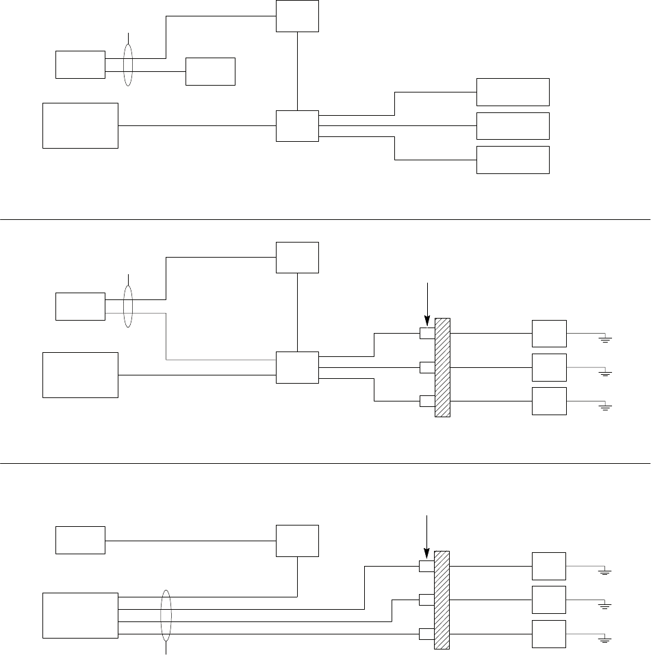
CableRequirementsChapter2:Sitepreparation
Figure2-2SystemPowerCabling
E1_SysPwrCabling1.eps
RACK
MGB Rack
Customer
Supplied
Customer
Supplied
Customer
Power
+27 V
PDU
+27 V Radio Shelf
Radio Shelf
Radio Shelf
BCU
AE
AC
AC
AC
AL
AL
**
** When using a Motorola rack, only the BCU and the frame need to be cabled to the MGB.
When using a non-Motorola rack, all items must be cabled to the MGB.
RRH STYLE 1
MGB
Customer
Supplied
Customer
Supplied
Customer
Power
-48 V
PDU
-48 V
RRH
RRH
RRH
BCU Surge suppressors
and filters *
Building
Entrance/Exit
AE
AK
AK
AK
AB
AB
AB
AL
AL
* Surge suppressors and filters are customer supplied.
MGB = Master Ground Bus
RRH STYLE 2
MGB
Customer
Supplied
Customer
Supplied
Customer
Power
-48 V RRH
RRH
RRH
BCU
Surge suppressors
and filters *
Building
Entrance/Exit
AB
AB
AB
AL
* Surge suppressors and filters are customer supplied.
MGB - Master Ground Bus
2-1268P09308A55-6
FEB2010
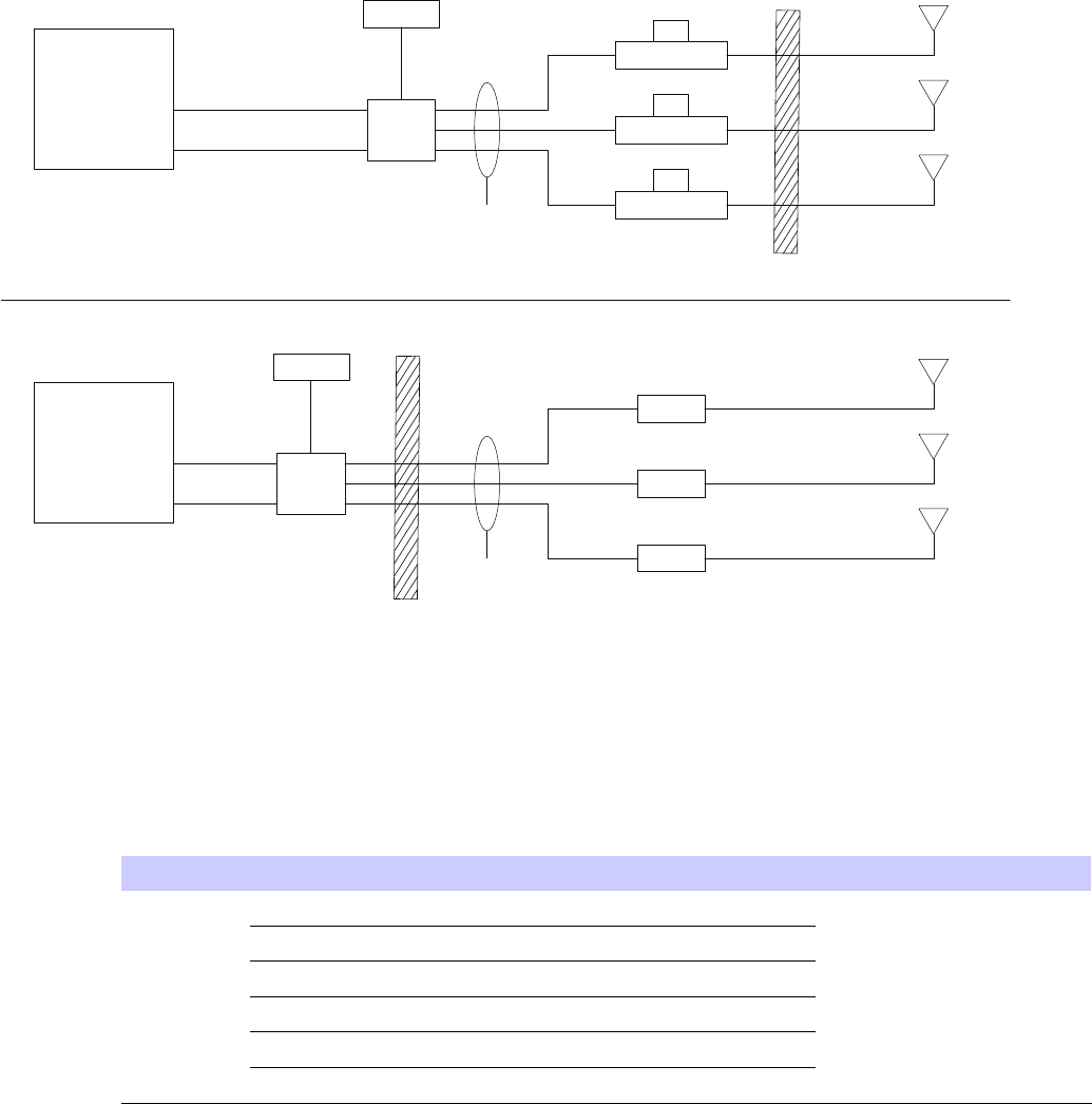
LTEeNodeBIndoorHardwareInstallationeNodeBCableDescriptions(min90Cinsulationrating)
Figure2-3SystemDataCabling
E1_eNodeB_SysdataCable1.eps
RRH
Customer
Termination
Customer I/O
Ethernet
BCU
Fiber Optic
RFGPS
AM
AA RRH
RRH
RRH
Customer
Supplied
Antenna
RF
AA
AA
AG
AN Customer
Supplied
Antenna
RF
Customer
Supplied
Antenna
RF
RACK
Customer
Termination
Customer I/O
Ethernet
BCU
Fiber Optic
RFGPS
AM
AD
AF *
* Cable AF connects RF signal between the
TRANSMIT OUT and TX on the Radio Shelf.
Radio Shelf
AF *
Radio Shelf
AF *
Radio Shelf
Customer
Supplied
Antenna
RF
AD
AD
AG
AN Customer
Supplied
Antenna
RF
Customer
Supplied
Antenna
RF
Building
Entrance/Exit
Building
Entrance/Exit
eNodeBCableDescriptions(min90Cinsulationrating)
Table2-4eNodeBCableDescriptions
CablelabelPartnumberDescriptionWhereused
SYKN89046m(19.68ft),FiberOpticCable
SYKN890520m(65.6ft),FiberOpticCable
SYKN890640m(131.2ft),FiberOpticCable
SYKN890760m(196.8ft),FiberOpticCable
SYKN890880m(262.4ft),FiberOpticCable
AA
SYKN8909100m(328.0ft),FiberOpticCable
RemoteBasedeNodeB
Continued
68P09308A55-62-13
FEB2010

eNodeBCableDescriptions(min90Cinsulationrating)Chapter2:Sitepreparation
Table2-4eNodeBCableDescriptions(Continued)
CablelabelPartnumberDescriptionWhereused
SYKN885920m(65.6ft),8AWG—RRHDC
PowerCable(105Crated)
SYKN88606m(19.68ft),10AWG—RRHDC
PowerCable(105Crated)
SYKN886440m(131.2ft),8AWG—RRHDC
PowerCable(105Crated)
SYKN886360m(196.8ft),6AWG—RRHDC
PowerCable(105Crated)
SYKN886280m(262.4ft),6AWG—RRHDC
PowerCable(105Crated)
AB
SYKN8861100m(328.0ft),6AWG—RRHDC
PowerCable(105Crated)
RemoteBasedeNodeB
ACSTKN4129RadioPowerCables—PwrCableto
connectRadioShelftoPDU
frame-basedeNodeB
ADSTKN4134RadioFiberCables/Transceivers—
3-footbercablewithtwooptical
transceiversusedtointerconnectthe
BCUtoeachRFRadio
frame-basedeNodeB
AESTKN4128BCUIIPowercableframe-basedeNodeB,
RemoteBasedeNodeB
AFSTKN4130RadioRFCables—Transmitcable
fromtheradiotothelter/duplexer
frame-basedeNodeB
AGSGKJ400050-FootGPSCable—50-FootRFGPS
Cable
frame-basedeNodeB,
RemoteBasedeNodeB
T472AC76m(250ft),RGPScable—Includes
receiverandcablesinpre-cutlengths
frame-basedeNodeB,
RemoteBasedeNodeB
AH
T472AE304m(998ft),RGPScable—Includes
receiverandcablesinpre-cutlengths.
frame-basedeNodeB,
RemoteBasedeNodeB
AICustomerDCpowercable,VW-1#8–#10AWG,
10m(32.8ft),ULtemperaturerating
105°C(167°F).
RemoteBasedeNodeB
AK3088961T10Powercable,femaleconnectoron
oneendwithtwowiresontheother
end,1000mm+/-200mm,2stranded
cables/wires(blackandred),8AWG
RemoteBasedeNodeB
ALCustomerGroundcable,6AWG,lengthneed
determinedbysiteconguration
frame-basedeNodeB,
RemoteBasedeNodeB
AMCGDS19797321CustomerI/Ocable,partofSGLN8484,
connectorononeendandloosewires
ontheother
frame-basedeNodeB,
RemoteBasedeNodeB
ANCustomerEthernet,RJ45connectors,
straight-through,shieldedCAT5e,90
m,max.24AWGsolidconductor
frame-basedeNodeB,
RemoteBasedeNodeB
2-1468P09308A55-6
FEB2010
LTEeNodeBIndoorHardwareInstallationToolsrequiredforinstallingtheeNodeBcomponents
ToolsrequiredforinstallingtheeNodeBcomponents
■■■■■■■■■■■■■■■■■■■■■■■■■■■■■■■■■■■■■■■■■■■■■■■■■■■■■■■■■■■■■
■
■
ThefollowingtoolsarerequiredtoperformtheinstallationofeNodeBcomponents:
Torquewrenches:
•SMATorqueWrench
•TypeNconnectortorquewrench
•Torquedrivercapableofdrivingbits1.1N-m(10in-lb),1.3N-m(12in-lb),1.8N-m(16
in-lb),4.7N-m(42in-lb),and5.1N-m(45in-lb)
•Torquedrivercapableoftorquing10mmsocketto5.1N-m(45in-lb)
Bitdriverandbits:
•Bitdriver
•T15Torxbit
•T20Torxbit
•T25Torxbit
•T30Torxbit
•T20Torxsecuritybit
•T30Torxsecuritybit
•Flatbladescrewdriverbit
Generaltools:
•10mmsocket
•13mmsocket(toinstallM8nutsonRRH)
•19mmsocket(forM12bolts)
•3-inchsocketextension
•10mmnutdriver
•Wirestrippers
•Cableinsulationstrippingtool(example:Greenlee1900)
Recommendedtools:
•Sidecutters
•6-inchbitdriverextension
68P09308A55-62-15
FEB2010
ToolsrequiredforinstallingtheeNodeBcomponentsChapter2:Sitepreparation
2-1668P09308A55-6
FEB2010

Chapter
3
Frame-basedeNodeBInstallation
■■■■■■■■■■■■■■■■■■■■■■■■■■■■■■■■■■■■■■■■■■■■■■■■■■■■■■■■■■■■■
■
■
■
■
Theproceduresdescribedinthischapterrelatetotheframe-basedeNodeBsystemwhichis
+27Vdconly .
68P09308A55-63-1
FEB2010
OverviewChapter3:Frame-basedeNodeBInstallation
Overview
■■■■■■■■■■■■■■■■■■■■■■■■■■■■■■■■■■■■■■■■■■■■■■■■■■■■■■■■■■■■■
■
■
•OperatingTemperature–Operatingtemperaturerangeonpage2-10.Installtheequipment
inanenvironmentcompatiblewiththemaximumambienttemperatureoftheequipment.
•ReducedAirFlow–Installtheequipmentintheracksuchthattheamountofairow
requiredforsafeoperationoftheequipmentisnotcompromised.
•MechanicalLoading–Mounttheequipmentintheracktopreventahazardouscondition
duetounevenmechanicalloading.
•CircuitOverloading–Useappropriateequipmentnameplateratingswhenconnectingthe
equipmenttothesupplycircuit.Considertheeffectthatoverloadingofthecircuitsmay
haveonovercurrentprotectionandsupplywiring.
•ReliableGrounding–Groundingoftherack-mountedequipmentmustbereliable.Pay
attentiontothesupplyconnectionsotherthanthedirectconnectionstothebranchcircuit
(forexample,useofpowerstrips).
PlanthelocationoftheLTEeNodeBsystemwithintherack.
3-268P09308A55-6
FEB2010
LTEeNodeBIndoorHardwareInstallationOverview
Figure3-1Indoorsystem
E1_majorcomponents_eNodeB.eps
3X
Radio Shelves
BCUII
PDU
68P09308A55-63-3
FEB2010
OverviewChapter3:Frame-basedeNodeBInstallation
Figure3-2RadioFrameShelf
Radio Fan Tray
Ground Lug
Power InputRF Filter
(behind front panel)
3-468P09308A55-6
FEB2010
LTEeNodeBIndoorHardwareInstallationUnpackingEquipment
UnpackingEquipment
■■■■■■■■■■■■■■■■■■■■■■■■■■■■■■■■■■■■■■■■■■■■■■■■■■■■■■■■■■■■■
■
■
Verifythecontentsofallshipmentsforcompleteness,accuracy ,andserviceabilityofall
componentsbeforeinstallation.Theequipmentisshippedwithapackinglist,listingallthe
partsshipped.Onreceivingtheequipment,checkthepackinglisttoverifythatallitemsare
received.Checkallcablesfordamageandallhardwareforscratchesanddents.Download
orretrievetheappropriatedocumentationtoinstalltheproduct.ContactMotorolaifany
discrepancyexistsbetweenthepackinglistandthedeliveredmaterial.
68P09308A55-63-5
FEB2010
InstallationoftherackChapter3:Frame-basedeNodeBInstallation
Installationoftherack
■■■■■■■■■■■■■■■■■■■■■■■■■■■■■■■■■■■■■■■■■■■■■■■■■■■■■■■■■■■■■
■
■
TheInstallationoftheracksectionprovidesprocedurestoinstallandgroundtherack.
Rackandgroundcableinstallation
TheRackandgroundcableinstallationsectionprovidestheproceduretomountthestandard
19-inchracktotheoorandinstallthegroundcable.
TheLTEsystemcanbeinstalledina19-inchracksuppliedbyMotorolaoracustomer-supplied
rack.TheMotorolarackisrecommended,asitensuresthatthepropergroundpathisachieved
throughchassisgroundsthroughthePDUandRadioFilterShelfmechanicswithouttheuseof
separategroundcables.Ifanon-Motorolarackisused,agroundcablemustbeusedforeachof
thesecomponentsplustheBCUII,whichrequiresagroundcablewithanyracktype.
Aninsulatingpadisattachedtothebaseoftheracktoelectricallyisolatetherackfromtheoor.
Structuralengineerprerequisite
Ensurethattheprocedure,tools,andequipmentrequiredtomounttheracktotheoorare
speciedbyaStructuralEngineer.
Requireditems
Thefollowingitemsarerequired:
•Rack
•10mmsocket
•19mmsocket
•6plasticshoulderwashers
•Torquedriver
•Crimpertool-AndersonPowerProductspartnumber1368-Hydraulichandtool,maximum
cablesizeof300MCM.
•6carbonsteelgrade8.8boltsM12orotherboltsasdeterminedbystructuralengineer-
customersupplied.
•Otheritems,speciedbythestructuralengineer,thatarerequiredtoinstalltherack.
•Customersuppliedgroundcable,6AWGorlargerdiameter.
•Two-holegroundlugandmountingnuts-partofrackhardwarekit.
3-668P09308A55-6
FEB2010

LTEeNodeBIndoorHardwareInstallationRackandgroundcableinstallation
Installingrackandgroundcable
PerformthestepsinProcedure3-1toinstalltherackandgroundcable.
Procedure3-1Installingrackandgroundcable
1Mounttheracktotheoorusingthehardware,tools,andproceduresdened
bythestructuralengineer .
NOTE
Motorolarecommendsusingcarbonsteelgrade8.8M12bolts.
2RoutethegroundcablebetweentheMasterGroundBar(MGB)andtherack.
NOTE
Groundcablesmustnothavesharpbends.
3Stripinsulationfromtheframeendofthegroundcable.
Attachthe2-holelugtotherack-endofthegroundcable.
4
Eitherusetheappropriatecrimpingtoolorsolderthelugtothecable.
Attachtheendofthegroundcablewiththe2-holelugtothetwoterminal
studsatthetopoftherack.Using2nuts,10mmsocketandratchet,tighten
thenutsto5.1N-m(45in-lb).
5
RefertoFigure3-3forlocationofgroundterminalstudsontherack.
6CutthegroundcabletolengthandconnectittotheMasterGroundBar .
7VerifythattheMasterGroundBarisconnectedtoasolidearthground.
68P09308A55-63-7
FEB2010
RackandgroundcableinstallationChapter3:Frame-basedeNodeBInstallation
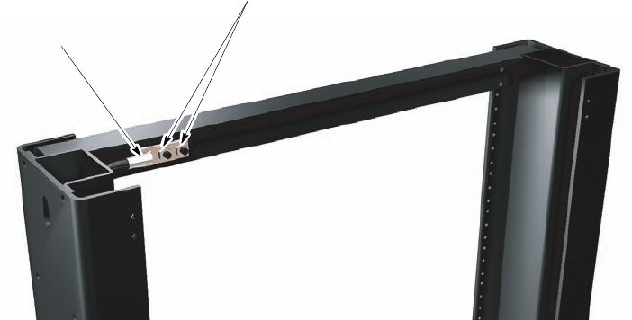
Figure3-3LocationofgroundterminalsonaMotorolarack
Earth Ground
Terminal Studs
Ground Cable With
2-hole Lug Fastened
To Ground Terminals
Rack
(top/rear view, shown
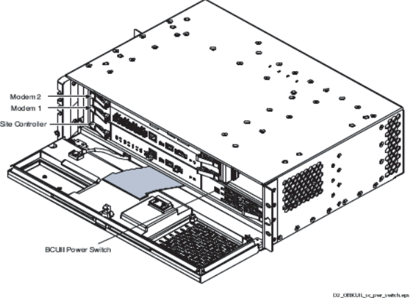
partially cut away)
3-868P09308A55-6
FEB2010

LTEeNodeBIndoorHardwareInstallationInstallingthe+27Vdc(PDU)
Installingthe+27Vdc(PDU)
■■■■■■■■■■■■■■■■■■■■■■■■■■■■■■■■■■■■■■■■■■■■■■■■■■■■■■■■■■■■■
■
■
TheInstallationofthePowerDistributionUnit(PDU)sectionprovidestheproceduretoinstall
thePDU.
Theconnecting+27Vdcpowersectionprovidesthefollowinginformation:
•Attachingthecontact/lugs,connector,andcableclamponthe+27Vdcpowerinputcable
wires.
•Connectingthe+27VdcinputpowercabletotherearofthePDU.
•Routingthelooseendsofthewirestothesite+27Vdcsourceforconnection.
Requiredmaterialsandtools
Thefollowingmaterialsandtoolsarerequired:
•One+27VdcPowerInputCable(DC)-customersupplied.
NOTE
MotorolarecommendstheuseofRedwireforfeed(+V)andBlackwirefor
return(-V).
•Crimptoolappropriateforwiresizeandlugbeingused.
•Wirestripper/cutters.
•DigitalMulti-Meter(DMM)FlukeModel8062AwithY8134testleadkitorequivalent;used
forprecisionDCandACmeasurements,requiring4-1/2digits.
InstallingthePDU
PerformthefollowingproceduresintoinstallthePDUinthe19-inchrack.
Procedure3-2AdjustingMountingEars
1
NOTE
Use+27VdcpowerPDUwiththepartnumberSTLN6905
Continued
68P09308A55-63-9
FEB2010

InstallingthePDUChapter3:Frame-basedeNodeBInstallation
Procedure3-2AdjustingMountingEars(Continued)
2Adjustthesideearsasfollows:
NOTE
ThePDUandallotherLTEframeequipmentcanbemountedinto
therackinaforwardorrearwardposition.ThePDU,BCUII,and
RadioFilterShelfareprovidedwithmountingearsinstalled,so
thatthesecomponentsareintheforwardpositionintherack.
Ifdesired,themountingearscanbechanged,sothePDUresidesintherear
positionwithintherack.
1.DisassembletheleftandrightmountingearsfromthePDUsidebrackets
usingaT20driver .
2.ReinstalltheleftandrightmountingearsonthePDUsidebracketat
thefrontpositionusingaT20driver.TorquetheM4screwsto1.8N-m
(16in-lb).
PerformthefollowingproceduretoinstallthePDU.
Procedure3-3MountingPDUintoRack
1MountthePDUintothe19-inchrackasfollows:
UsethescrewsprovidedwiththePDU.Ifotherscrewsaretobeused,then
obtainfourscrewswhichareatleast10mm(3/8inch)long.
NOTE
TheM5screwsareattachedinabagtotherearbracket.
2MountthePDUinthebottommostRackUnit.Installtwoscrewsperside
usingaT25Torxbitandtorqueto4.7N-m(42in-lb).
PerformthefollowingproceduretogroundthePDU.
Procedure3-4GroundingPDU
1
NOTE
Performthissteponlyifanon-Motorolarackisused.19-inchracks
thatarepaintedonthe19-inchmountingrailfrontfacerequire
anexternalPDUgroundcable.
Continued
3-1068P09308A55-6
FEB2010

LTEeNodeBIndoorHardwareInstallationInstallingthePDU
Procedure3-4GroundingPDU(Continued)
ThePDUissuppliedwith2-holecrimplugsfor1/0AWGstandard
or2AWGhigh-strandcountexwire.Ifanothertypeofcableis
required,orderanewlugasneeded.Thenewlugandgroundcable
mustequalthesizedeterminedfortheDCInputCablesinthe
precedingsteps.EnsurethatthelugmeetsthecriteriainTable3-2.
Theexpectedloadconditionandcablelengthdeterminesthewire
gaugerequiredforyoursystem.SeeTable2-2.
2Crimpthetwo-holelugontotheGroundCable.
3InstallthelugontothePDURearBracket.SecurethelugwithtwoM6Nylock
nutstorquedto5.1N-m(45in-lb).
4CutthegroundcabletolengthandconnectittoMasterGroundBar.
PerformthefollowingproceduretoconnectpowertothePDU.
Procedure3-5ConnectthePDUtopower
1EnsurethatthegroundcableisconnectedbetweentherackandtheMaster
GroundBar.
2Ensurethatthe+27VdcPowerInputCable(DC)isnotconnectedtothemain
+27Vdcpowersource.
Turnoffthemain+27Vdcpowersource.
ConrmthatthepowerisswitchedOFFusingaDVM.
3ThePDUissuppliedwith2-Holecrimponlugsfor1/0AWGstandardor2
AWGhigh-strandcountexcable.Ifyourequireanothertypeofcable,order
newlugsasneeded.EnsurethatthelugsmeetthecriteriainTable3-2
NOTE
Theexpectedloadconditionandcablelengthdeterminethewire
gaugerequiredforthesystem.SeeTable2-2.
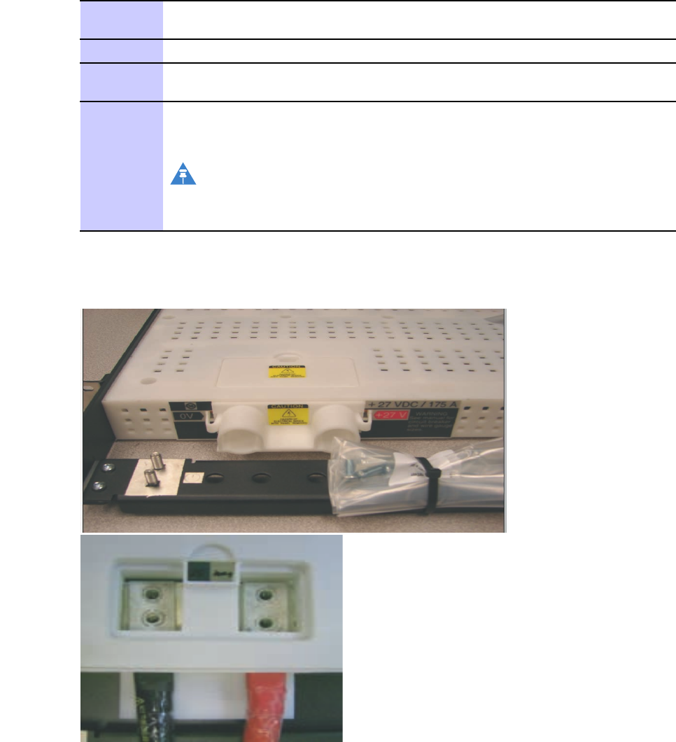
4Removethelugcoverandservicecoverusingtheirrespectivesnaps.
5Insertthetwo-holelugsthroughtherearofthePDU,sothattheholesinthe
lugsalignwiththeholesinthelugmountingplates.
6InstalltwoM6atwashersandtwoM6x16screwsintoeachlug(4washers
and4nutstotalforthe2lugs)usingaT30Torxdriver.
NOTE
Theatwashersandscrewsaresuppliedinthebagsziptiedtothe
PDUrearbracket.
Leavethescrewsloosesothatthelugscanbeadjustedside-to-side.
Continued
68P09308A55-63-11
FEB2010
InstallingthePDUChapter3:Frame-basedeNodeBInstallation
Procedure3-5ConnectthePDUtopower(Continued)
7Replacethelugcoverwhileadjustingthecablestoensurethatthecover
canbesnappedintoposition.
8Tightenthelugscrewsto5.1N-m(45in-lb)andreplacetheservicecover.
9Installziptiesaroundthecablesthroughtherearbracketandpulltightfor
sufcientstrainrelief.
10Connecttheotherendofthe+27Vdcpowerandreturnwirestothepower
source.
NOTE
Donotturnonthepowersourceatthistime.Thismustbedone
aftertheinstallationandcablingiscomplete.
Figure3-4PDUpowerconnection
ti-cdma-05694.eps
3-1268P09308A55-6
FEB2010
LTEeNodeBIndoorHardwareInstallationInstallingthePDU
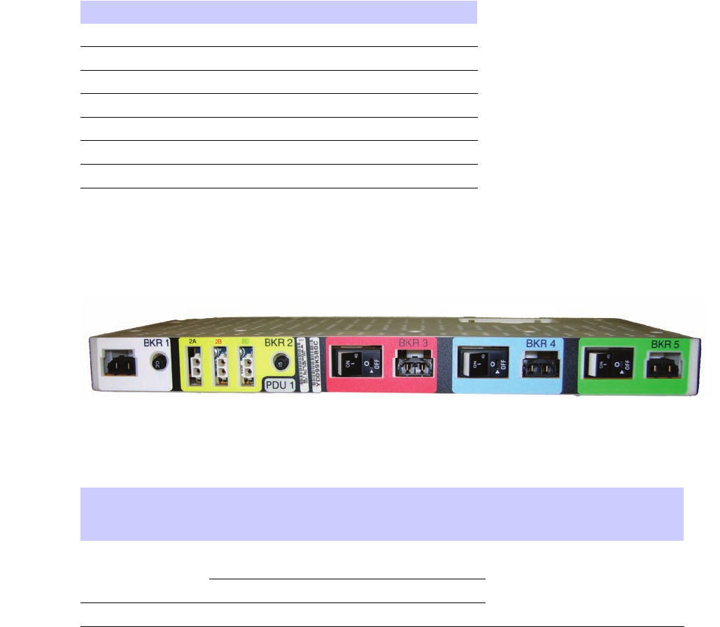
Table3-1Frame-basedeNodeBcableconnectionstoPDUbreakers
ConnectorLoad
BKR1BCUII
BKR2AAuxiliaryEquipment#1
BKR2BAuxiliaryEquipment#2
BKR2CAuxiliaryEquipment#3
BKR3RadioSector1
BKR4RadioSector2
BKR5RadioSector3
Figure3-5PDUFront
PDU front.eps
Table3-2Lugcriteria
PDUinputLTEPDUinput
labeltext
Crimplug'scenter–to
–centerspacingofM6
(1/4”)screwholes
Wiregaugecompatibility
forsuppliedlugs
+27Vdc(red
arrow)
19mm(3/4inch)
+27Vdc
0V(blackarrow)16mm(5/8inch)
GroundFrameground16mm(5/8inch)
1/0standardcable
68P09308A55-63-13
FEB2010
InstallationoftheBCUIIChapter3:Frame-basedeNodeBInstallation
InstallationoftheBCUII
■■■■■■■■■■■■■■■■■■■■■■■■■■■■■■■■■■■■■■■■■■■■■■■■■■■■■■■■■■■■■
■
■
TheInstallationoftheBCUIIsectionprovidesgeneralinformationandproceduresforinstalling
aBaseControlUnitII(BCUII).
BCUIIisdesignedasanindoorcomponentthatcanbemountedonastandard19-inchrack.
Figure3-6showstheBCUII.
Figure3-6BCUIIphysicaldesign
ti-cdma-05694.eps
Requiredmaterialsandtools
Thefollowingmaterialsandtoolsarerequired:
•BCUIISG1756
•T15driver
•T10driver
•T25torxbit
•10mmsocket
•Customersuppliedgroundcable,lengthdeterminedbydistancefromtheunittothe
masterground.
3-1468P09308A55-6
FEB2010

LTEeNodeBIndoorHardwareInstallationBCUIIinstallation
•Wirestripper/cutters.
•DigitalMulti-Meter(DMM)FlukeModel8062AwithY8134testleadkitorequivalent;used
forprecisionDCandACmeasurements,requiring4-1/2digits.
BCUIIinstallation
Procedure3-6AdjustingMountingEars
1Adjustthesideearsasfollows:
NOTE
TheBCUIIandallotherLTEframeequipmentcanbemountedinto
therackinaforwardorrearwardposition.ThePDU,BCUII,and
RadioFilterShelfareprovidedwithmountingearsinstalled,so
thatthesecomponentsareintheforwardpositionintherack.
Ifdesired,themountingearscanbechanged,sotheBCUIIresidesinthe
rearpositionwithintherack.
1.DisassembletheleftandrightmountingearsfromtheBCUIIside
bracketsusingaT10driver.
2.ReinstalltheleftandrightmountingearsontheBCUIIsidebracketat
thefrontpositionusingaT10driver.TorquetheM3screwsto1.12
N-m(10in-lb).
NOTE
Leftmountingeargoestotherightsideandtherightmounting
eargoestotheleftside.
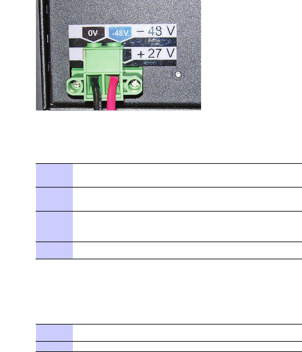
PerformthestepsinProcedure3-7toinstallpowercablestotheBCUII.
Procedure3-7CablingPowertoBCUII
1Stripeachwire12.7mm(1/2inch).
2InsertwiresaccordingtothecolorcodeonthebackoftheBCUII.Tighten
thescrewsto1.3N-m(12in-lb).SeeFigure3-7.
3Plugtheblack2-pinconnectorintothefrontofthePDUBrkr1.
Routethecablewiththegreenscrewterminalconnectortowardstherear
overtheleftmountingear.
Continued
68P09308A55-63-15
FEB2010
BCUIIinstallationChapter3:Frame-basedeNodeBInstallation
Procedure3-7CablingPowertoBCUII(Continued)
4Threadthecablethroughtheslotintheleftsidebracketjustbehindthe
plastichousingandacrosstherearofthePDU.
5InstalltheBCUIIintherack.
NOTE
ThepowercablemustbepluggedintoBCUIIduringtheBCUII
installationprocedure.
Figure3-7CablingPowerto+27VdcBCUII
-27V.eps
PerformthestepsinProcedure3-8toinstalltheBCUII.
Procedure3-8BCUIIInstallation
1PlacearackmountingscrewinthefthholeabovethePDUrightearbracket.
LeavethescrewheadspacedoutfromtherackfacetoallowfortheBCUII
mountingeartobeinstalledoverthescrewhead.
2PlacearackmountingscrewinthefthorsixthholeabovethePDUleftear
bracket.Leavethescrewheadspacedoutfromtherackfacetoallowthe
BCUIImountingeartobeinstalledoverthescrewhead.
Continued
3-1668P09308A55-6
FEB2010

LTEeNodeBIndoorHardwareInstallationBCUIIinstallation
Procedure3-8BCUIIInstallation(Continued)
3HangtheBCUIIonthetwomountingscrewsandmatethegreentwo-position
ScrewTerminalConnectorintotheBCUIIPowerSupplyontherear.
Tightenthetworetainingscrewsintothematingconnectorto1.3N-m(12
in-lb.
4UseaT25torxbittoinstalltheremaining(twoscrewsperside)rackmounting
screws.Torqueallrackmountingscrewsto4.7N-m(42in-lb).
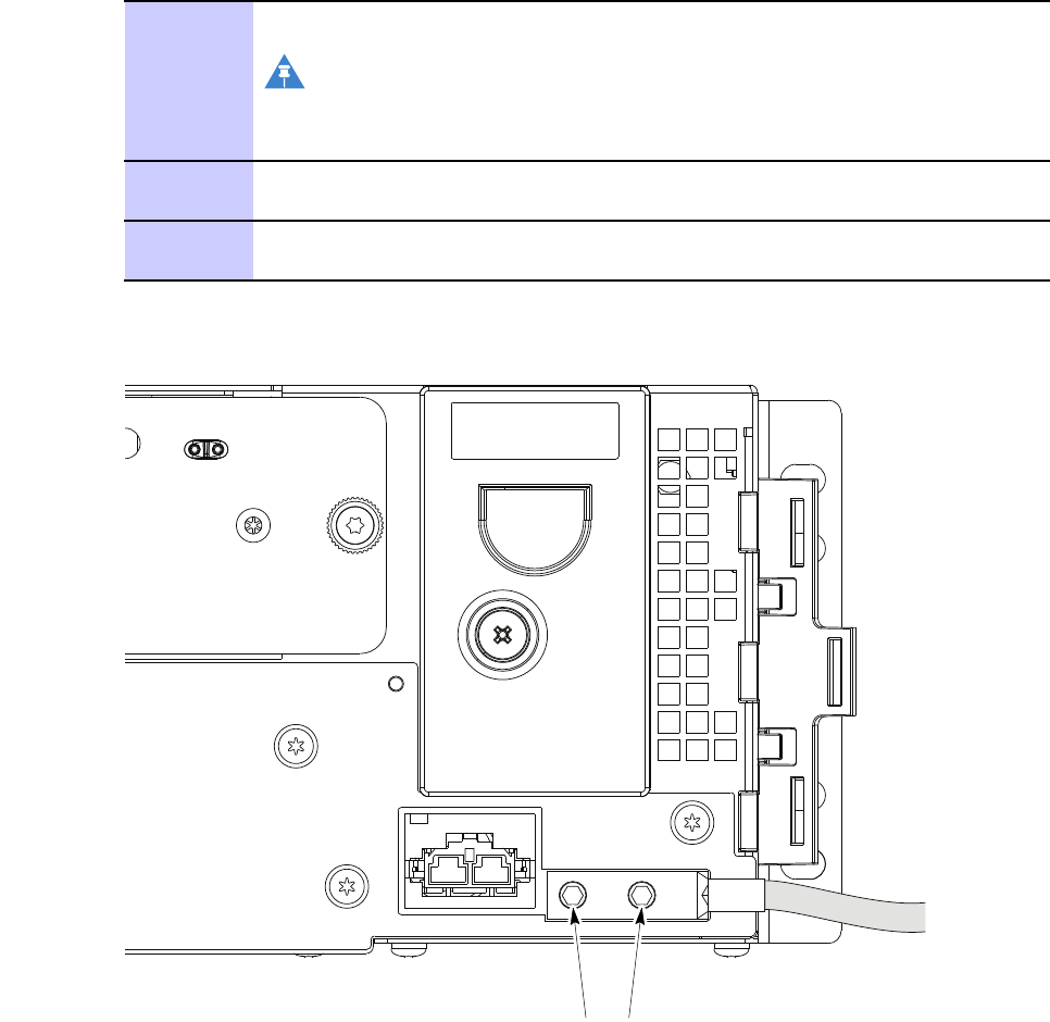
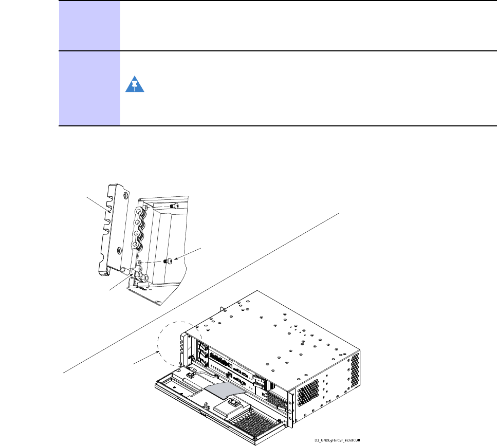
ConnectingGroundtoBCUII
PerformthestepsinProcedure3-9toconnectthegroundcabletoBCUII.
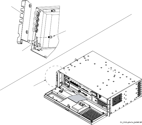
Procedure3-9ConnectinggroundtoBCUII
1Removethegroundlugfromtheleftinsidewallusinga10mmsocketor
nutdriver.
2CrimptheBCUIIgroundlugontoa6AWGwire.
3Attachthegroundwiredoubleholelugtothethreadedstudslocatedatthe
BCUIIcardcagefrontleftcorner.
SecurethegroundwirelugtothethreadedstudswiththetwoM6nuts.Using
a10mmsocketandtorquedriver ,tightenthenutsto5.1N-m(45in-lb).
4Connecttheotherendofthegroundwiretothemastergroundbar.
NOTE
Donotreinstallbercover(feedthroughplate)atthistime.Setit
asideforsafekeepinguntiltheberinstallationiscompletedlater .
68P09308A55-63-17
FEB2010
BCUIIinstallationChapter3:Frame-basedeNodeBInstallation
Figure3-8BCUIIGrounding
Fiber Cover
Ground Lug
2X Screws
See Detail A
Detail A
D2_GNDLgFb rCvr_InDrBCUII
3-1868P09308A55-6
FEB2010
LTEeNodeBIndoorHardwareInstallationInstallationofRadio/FilterShelf(RFS)andFrameMountedRadioHead
InstallationofRadio/FilterShelf(RFS)andFrame
MountedRadioHead
■■■■■■■■■■■■■■■■■■■■■■■■■■■■■■■■■■■■■■■■■■■■■■■■■■■■■■■■■■■■■
■
■
Figure3-9Radio/FilterShelf
FRONT VIEW LTE_shelf_frt.eps
0V
+27V
TRANSMIT STATUS
TRANSMIT
OUT 0
KIT
NUMBER
SERIAL
NUMBER
TX-1
TX/RX-0
LTE
FWD REF
VSWR
TX-0 TX/RX-1
FWD REF
MODULE STATUS
CONTROL
PROCESSOR
TRANSMIT
OUT 1
D4+0
D4+1
D4+0
ENET
D4+1
VSWR+27V
0V GND
TX/RX-0 TX -0FWD REF
TX/RX-1 TX -1
FWD REF
FAN TRAY
TRANSMIT
STATUS
MODULE
STATUS
CONTROL
PROCESSOR
ENET
TRANSMIT
OUT 1
TRANSMIT
OUT 0
D4+0
D4+0
LED
D4+1
LED
D4+1
CABLE
CLIP
CABLE
CLIP
ThissectionprovidestheproceduretoinstalltheRadio/FilterShelf(RFS).
Thefollowingmaterialsandtoolsarerequired:
•RFSSTLN6903
•RFHeadSTWF4000
•Customersuppliedgroundcable,lengthdeterminedbydistancefromtheunittothe
masterground(requiredonlyifnotusingtheMotorolaprovidedrack).
•T20Torxbit
•10mmsocket
•T25Torxbit
•Wirestripper/cutters
68P09308A55-63-19
FEB2010
InstallationofRadio/FilterShelf(RFS)andFrameMountedRadioHeadChapter3:Frame-basedeNodeBInstallation
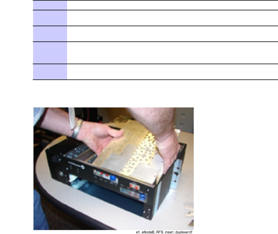
PerformthefollowingproceduretoinstalltheRFSDuplexer.
Procedure3-10InstallingRFSDuplexer
1MovethetwoRFcablesoutoftheway .InserttheDuplexerintotheRFS.
2PulltheDuplexertowardsthefront,sotheDuplexerbodyrestsagainstthe
insidefrontfaceoftheRFSchassis.
3UsingaT20Torx,screwtwoM4screwsthroughthefrontfaceoftheRFSinto
theDuplexerbody .Torqueto2.25N-m(20in-lb).
4Witha10mmsocketand3-inchsocketextension,securetheDuplexerto
thetwoM6studsinthebottomoftheRFSshelfwithtwoM6nuts.Torque
to5.1N-m(45in-lb).
5MatethetwoRFcablesattherearoftheDuplexer.Ensurethatthecable
bendsarenolessthan6mm(1/4inch)radius.
Figure3-10InstallingDuplexer
TheRFScanbemountedintotherackinaforwardorrearwardposition.TheRFSisprovided
withthemountingearsinstalledsothatitisintheforwardpositionintherack.
3-2068P09308A55-6
FEB2010

LTEeNodeBIndoorHardwareInstallationInstallationofRadio/FilterShelf(RFS)andFrameMountedRadioHead
Procedure3-11AdjustingMountingEars
1
NOTE
UseRFSwiththepartnumberSTLN6903.
2Adjustthesideearsasfollows:
NOTE
TheRadioFilterShelfandallotherLTEframeequipmentcanbe
mountedintotherackinaforwardorrearwardposition.ThePDU,
BCUII,andRFSareprovidedwithmountingearsinstalled,sothat
thesecomponentsareintheforwardpositionintherack.
Ifdesired,themountingearscanbechanged,sotheRFSresidesintherear
positionwithintherack.
1.DisassembletheleftandrightmountingearsfromtheRFSsidebrackets
usingaT20driver .
2.ReinstalltheleftandrightmountingearsonthePDUsidebracketat
thefrontpositionusingaT20driver.TorquetheM4screwsto2.25
N-m(20in-lb).
NOTE
Theleftmountingeargoestotherightsideandtherightmounting
eargoestotheleftside.
Procedure3-12InstallingRFS
1Forboththeleftandrightsideofthe19-inchrack,installonerackmounting
screwinthefthholeabovetheBCUIIMountingEarBracket.Leavethe
screwheadspacedoutfromtherackfacetoallowtheBCUIIMountingEar
tobeinstalledoverthescrewhead.
2WiththeRFSorientedsothattheDuplexeristowardsthebottom,installthe
RFSsothatthecenterkeyholeintheSideMountingBracketslipsoverthe
rackmountingscrewsinstalledinstep1.
3SecuretheRFStotherack.UseaT25Torxbittoinstalltheremainingrack
mountingscrewsto4.7N-m(42in-lb).
68P09308A55-63-21
FEB2010

RFSpowercableinstallationChapter3:Frame-basedeNodeBInstallation
PerformthefollowingproceduretoinstalltheFameMountedRadioHead.
Procedure3-13InstallingFrameMountedRadioHead
1WiththeRadioorientedwiththehandletotheleft,slidetheRadiointothe
RFSuntilfullyseated.
2UsingaT20Torx,screwthetwoblackthumbscrewsonthefrontoftheRadio
intotheRFS.Torqueto2.25N-m(20in-lb).
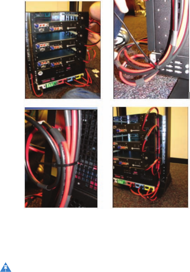
RFSpowercableinstallation
OnepowercableisrequiredperRFS.
PerformthestepsinProcedure3-14toinstalltheDCpowercabletotheRFS.
Procedure3-14InstallingRFSpowercable
1PlugtheRFScablesintothePDUbreakers4,5,and6.Maketheconnections
pertheinformationinTable3-1,wheresector1isthebottom-mostRFSinthe
frame.
2Installcabletiebracketstotheradioltershelf(snapinplace).Usezipties
totiethepowercablestothecabletiebracketsasshowninFigure3-11.
3-2268P09308A55-6
FEB2010
LTEeNodeBIndoorHardwareInstallationRFSGroundCableInstallation
Figure3-11Tyingpowercablestothecabletiebrackets
RFSGroundCableInstallation
PerformthestepsinProcedure3-15toaddanexternalgroundcabletotheRFS.
NOTE
ExecuteProcedure3-15onlyiftherackisnotaMotorolarack.TheMotorolarackhas
nopaintonthe19-inchmountingrailfrontface.Groundcurrentcantravelthrough
thePDUchassistotheframegroundlug.Other19-inchracksthathavepaintonthe
19-inchmountingrailfrontfacerequireanexternalRFSgroundcable.
68P09308A55-63-23
FEB2010
RFSGroundCableInstallationChapter3:Frame-basedeNodeBInstallation
Procedure3-15InstallingRFSgroundcable
1Crimpthe2–holecrimplugontothecustomersuppliedgroundcable.
NOTE
TheRFSissuppliedwith2-holecrimplugsfor6AWGstandard
wire.
2InstallthelugontotheRFS.
3Usinga10mmsocketanddriver,securethelugwith2M6nutstorqued
to5.1N-m(45in-lb).
Figure3-12RFSgroundcableconnection
M6 Nuts
3-2468P09308A55-6
FEB2010
LTEeNodeBIndoorHardwareInstallationInstallationoftheGPS
InstallationoftheGPS
■■■■■■■■■■■■■■■■■■■■■■■■■■■■■■■■■■■■■■■■■■■■■■■■■■■■■■■■■■■■■
■
■
InstallingRFGPSantennaandcable
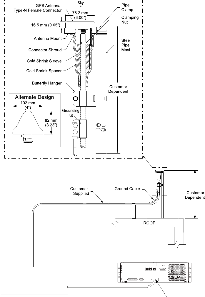
Figure3-13showsthecomponentsoftheRFGPS(RFGPS).
WhenmountingtheRFGPSAntennaconsiderthefollowingitems:
•ThemountingpipefortheRFGPSheadismountedverticallywithlessthanve(5)
degreesoftilt.
•TheRFGPSheadrequiresaclearviewofthesky ,preferablywithinten(10)degreesofthe
horizoninalldirections.
•Themoreskythatisobservedincreasesthenumberofpotentialsatellitesthatcanbe
tracked,resultinginbetterRFGPSperformance.
•Duringnormaloperation,theRFGPSheadcontinuouslytracksaminimumoffour(4)
GPSsatellites.However,itistheoreticallypossibletooperatetheBTSbytrackingonly
one(1)GPSsatellite.Motoroladoesnotrecommendtrackingonlyone(1)GPSsatellite
unlesstherehasbeenanaccuratesitesurvey .
•PlacetheRFGPSheadwhereRFobstructionsoftheskyareminimal.Theskyincludes
everythingwithinten(10)degreesofthehorizoninalldirections.RFobstructionsinclude
buildings,towers,naturalrockformations,snow ,foliage,anddebris.
PerformthefollowingproceduretoinstalllocalGPS(RFGPS):
Procedure3-16InstallingRFGPSantennaandcabling
1DeterminethelocationfortheRFGPSSurgeProtectiondevice(preferablyat
theentrancetothebuilding).
2ConnecttheRFGPSSurgeProtectiondevicetothemastergroundbus(MGB).
3Determinethemountinglocation.
4
CAUTION
Ensurethataqualiedstructuralengineerveriestheroofstructure
onwhichthemountingpoleisattachedfortheweightoftheRFGPS
engineandmountinghardwareunderadverseconditionsinthe
installationarea.
InstallthemountingkitattheRFGPSlocation.Usetheappropriatemounting
boltsformountingsurface.
Continued
68P09308A55-63-25
FEB2010

InstallingRFGPSantennaandcableChapter3:Frame-basedeNodeBInstallation
Procedure3-16InstallingRFGPSantennaandcabling(Continued)
5AttachtheRFGPSantennaassemblytothemountingbracketandsecurethe
washerandcustomnutsupplied.SeeFigure3-13.
6AttachthegroundingkittothemountingpolewithU-boltsandsecureusing
thewashersandnutssupplied.SeeFigure3-13.
7ConnecttheNconnectorofthe50ft(15.24m)superexcabletotheRFGPS
antennacable.
8RoutetheotherendofthesuperexcabledownthepoleandtotheRFGPS
SurgeProtectiondevice.ConnectthecabletotheRFGPSSurgeProtection
device.Securecableusingcabletieswhereappropriate.
9Attachoneendofacable(customersupplied)totheRFGPSSurgeProtection
deviceandtheotherendtotheRFGPSconnectorontheBCUII.TheBCUII
connectorisanSMAstyleconnector.Securecableusingcabletieswhere
appropriate.
3-2668P09308A55-6
FEB2010
LTEeNodeBIndoorHardwareInstallationInstallingRFGPSantennaandcable
Figure3-13RFGPSinstallationandcomponentsdiagram
E1_eNodeB_RFGPS_cbl.eps
Surge Suppressor
Customer Supplied
Typically installed at
entrance to building
Customer
Supplied RF-GPS Connector
CUSTOMER I/O AP CONTROL
ENET -A ENET -B CUST. ENET
TDD RF-GPS
RGPS
STATUS
BCU II
68P09308A55-63-27
FEB2010
OptionalequipmentChapter3:Frame-basedeNodeBInstallation
Optionalequipment
■■■■■■■■■■■■■■■■■■■■■■■■■■■■■■■■■■■■■■■■■■■■■■■■■■■■■■■■■■■■■
■
■
Thissectioncontainsgeneralinformationandproceduresforinstallingtheoptionalequipment.
Quartz-highstabilityoscillator
TheQuartzhighstabilityoscillator(Q-HSO)isavailableasanoptionalequipmentto
accommodatecustomerswiththebackuptimingmodule.Sinceitisoptional,theQ-HSOmay
notbepresentinallinstallations.However ,ifitisinitiallyordereditisinstalledatthefactory .
Figure3-14BCUIIQ-HSOunit
ti-cdma-05694.eps
ti-cdma-05694.eps
Mounting Tab Slot
Q-HSO
Q-HSO
Rear View
9-Pin Sub-D Connector
9-Pin Sub-D Connector
Captive Thumbscrew
Mounting Tab
IftheQ-HSOisnotfactoryinstalled,performthestepsProcedure3-17toinstalltheunit.
3-2868P09308A55-6
FEB2010
LTEeNodeBIndoorHardwareInstallationQuartz-highstabilityoscillator
Procedure3-17Q-HSOinstallation
1InstalltheQ-HSObyinsertingthetabintotheslotintheBCUII.Referto
Figure3-14.PushtheQ-HSOuntilitseatsintheD-typeconnectoratthe
rearofthetray .
2UseaT20TorxbittoinstalltheQ-HSO.Torqueto2.25N-m(20in-lb)
3
NOTE
TheQ–HSOmustwarmupfor60minutestoreachasteadystate
beforeitcantakeoverforafailedGPSsignal.Iftheactivesite
controllercardrebootsduringthe60minutewarm-upperiod,
thetimerisreset,andtheQ–HSOmustwarmupforanother60
minutesbeforeuse.
TheREFFAULTLEDontheBCUIIcontrollercardlightswhentheQ–HSOis
rstinstalledbutturnsoffbythetimeitiswarmedup.
68P09308A55-63-29
FEB2010
Quartz-highstabilityoscillatorChapter3:Frame-basedeNodeBInstallation
3-3068P09308A55-6
FEB2010

Chapter
4
Installationoftheindoorportionsofthe
RemoteRFbasedeNodeB
■■■■■■■■■■■■■■■■■■■■■■■■■■■■■■■■■■■■■■■■■■■■■■■■■■■■■■■■■■■■■
■
■
■
■
68P09308A55-64-1
FEB2010
InstallationoftheBCUIIChapter4:InstallationoftheindoorportionsoftheRemoteRFbasedeNodeB
InstallationoftheBCUII
■■■■■■■■■■■■■■■■■■■■■■■■■■■■■■■■■■■■■■■■■■■■■■■■■■■■■■■■■■■■■
■
■
TheInstallationoftheBCUIIsectionprovidesgeneralinformationandproceduresforinstalling
aBaseControlUnitII(BCUII).
BCUIIisdesignedasanindoorcomponentthatcanbemountedonastandard19-inchrack.
Figure4-1showstheBCUII.
Figure4-1BCUIIphysicaldesign
ti-cdma-05694.eps
Requiredmaterialsandtools
Thefollowingmaterialsandtoolsarerequired:
•BCUIISG1756
•T15driver
•Customersuppliedgroundcable,lengthdeterminedbydistancefromtheunittothe
masterground.
•Wirestripper/cutters.
•DigitalMulti-Meter(DMM)FlukeModel8062AwithY8134testleadkitorequivalent;used
forprecisionDCandACmeasurements,requiring4-1/2digits.
4-268P09308A55-6
FEB2010

LTEeNodeBIndoorHardwareInstallationBCUIIinstallation
BCUIIinstallation
Procedure4-1AdjustingMountingEars
1Adjustthesideearsasfollows:
NOTE
TheBCUIIandallotherLTEframeequipmentcanbemountedinto
therackinaforwardorrearwardposition.ThePDU,BCUII,and
RadioFilterShelfareprovidedwithmountingearsinstalled,so
thatthesecomponentsareintheforwardpositionintherack.
Ifdesired,themountingearscanbechanged,sotheBCUIIresidesinthe
rearpositionwithintherack.
1.DisassembletheleftandrightmountingearsfromtheBCUIIside
bracketsusingaT10driver.
2.ReinstalltheleftandrightmountingearsontheBCUIIsidebracketat
thefrontpositionusingaT10driver.TorquetheM3screwsto1.12
N-m(10in-lb).
NOTE
Theleftmountingeargoestotherightsideandtherightmounting
eargoestotheleftside.
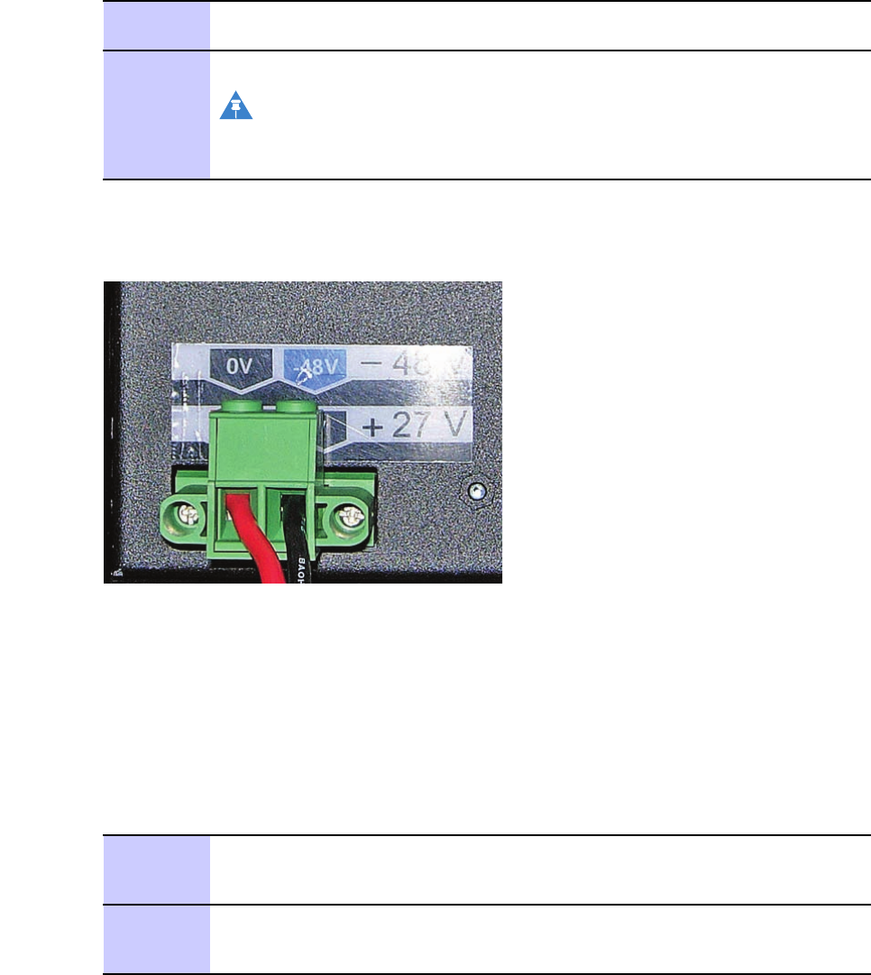
PerformthestepsinProcedure4-2toinstallpowercablestotheBCUII.
Procedure4-2CablingPowertoBCUII
1Stripeachwire12.7mm(1/2inch).
2InsertwiresaccordingtothecolorcodeonthebackoftheBCUII.Tighten
thescrewsto1.3N-m(12in-lb).SeeFigure4-2
3Plugtheblack2-pinconnectorintothefrontofthePDUBrkr1.
Routethecablewiththegreenscrewterminalconnectortowardstherear
overtheleftmountingear.
4Threadthecablethroughtheslotintheleftsidebracketjustbehindthe
plastichousingandacrosstherearofthePDU.
5InstalltheBCUIIintherack.
NOTE
ThepowercablemustbepluggedintoBCUIIduringtheBCUII
installationprocedure.
68P09308A55-64-3
FEB2010
BCUIIinstallationChapter4:InstallationoftheindoorportionsoftheRemoteRFbasedeNodeB
Figure4-2CablingPowerto–48VdcBCUII
-48V.eps
PerformthestepsinProcedure4-3toinstalltheBCUII.
Procedure4-3BCUIIInstallation
1PlacearackmountingscrewinthefthholeabovethePDUrightearbracket.
LeavethescrewheadspacedoutfromtherackfacetoallowfortheBCUII
mountingeartobeinstalledoverthescrewhead.
2PlacearackmountingscrewinthefthorsixthholeabovethePDUleftear
bracket.Leavethescrewheadspacedoutfromtherackfacetoallowthe
BCUIImountingeartobeinstalledoverthescrewhead.
3HangtheBCUIIonthetwomountingscrewsandmatethegreentwo-position
ScrewTerminalConnectorintotheBCUIIPowerSupplyontherear.
Tightenthetworetainingscrewsintothematingconnectorto1.3N-m(12
in-lb).
4UseaT25torxbittoinstalltheremaining(twoscrewsperside)rackmounting
screws.Torqueallrackmountingscrewsto4.7N-m(42in-lb).
ConnectingGroundtoBCUII
PerformthestepsinProcedure4-4toconnectthegroundcabletoBCUII.
Procedure4-4ConnectinggroundtoBCUII
1Removethegroundlugfromtheleftinsidewallusinga10mmsocketor
nutdriver.
2CrimptheBCUIIgroundlugontoa6AWGwire.
Continued
4-468P09308A55-6
FEB2010
LTEeNodeBIndoorHardwareInstallationBCUIIinstallation
Procedure4-4ConnectinggroundtoBCUII(Continued)
3Attachthegroundwiredoubleholelugtothethreadedstudslocatedatthe
BCUIIcardcagefrontleftcorner.
SecurethegroundwirelugtothethreadedstudswiththetwoM6nuts.Using
a10mmsocketandtorquedriver ,tightenthenutsto5.1N-m(45in-lb).
4Connecttheotherendofthegroundwiretothemastergroundbar.
NOTE
Donotreinstallbercover(feedthroughplate)atthistime.Setit
asideforsafekeepinguntiltheberinstallationiscompletedlater .
Figure4-3BCUIIGrounding
Fiber Cover
Ground Lug
2X Screws
See Detail A
Detail A
D2_GNDLgFb rCvr_InDrBCUII
68P09308A55-64-5
FEB2010
BCUIIinstallationChapter4:InstallationoftheindoorportionsoftheRemoteRFbasedeNodeB
4-668P09308A55-6
FEB2010

Chapter
5
InstallationoftheRRH
■■■■■■■■■■■■■■■■■■■■■■■■■■■■■■■■■■■■■■■■■■■■■■■■■■■■■■■■■■■■■
■
■
■
■
68P09308A55-65-1
FEB2010

InstallingtheRemoteRadioHeadChapter5:InstallationoftheRRH
InstallingtheRemoteRadioHead
■■■■■■■■■■■■■■■■■■■■■■■■■■■■■■■■■■■■■■■■■■■■■■■■■■■■■■■■■■■■■
■
■
TheRemoteRadioHead(RRH)isavailableinthreemodels:
•700MHz
•2.1GHz
•2.6GHz
Installingthe700MHzRRH
The700MHzRRHcanbeconguredintwoways:
•Wallmountconguration
•Polemountconguration
Performthefollowingproceduretoinstallthe700MHzRRHtoawall.
Procedure5-1700MHzRRHwallmountconguration
1Drillfourholesoftheappropriatesizeintothewallforthewallmount
anchorsasrecommendedbythestructuralengineer.Drilltheholesinthe
locationsasshown.
Continued
5-268P09308A55-6
FEB2010
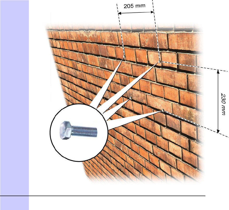
LTEeNodeBIndoorHardwareInstallationInstallingthe700MHzRRH
Procedure5-1700MHzRRHwallmountconguration(Continued)
2InstallthetoptwoM8boltsinthetoptwoslotsonthewall.Boltsshouldnot
betightened.Boltheadsshouldbespacedatleast15mmfromthewall.
Continued
68P09308A55-65-3
FEB2010
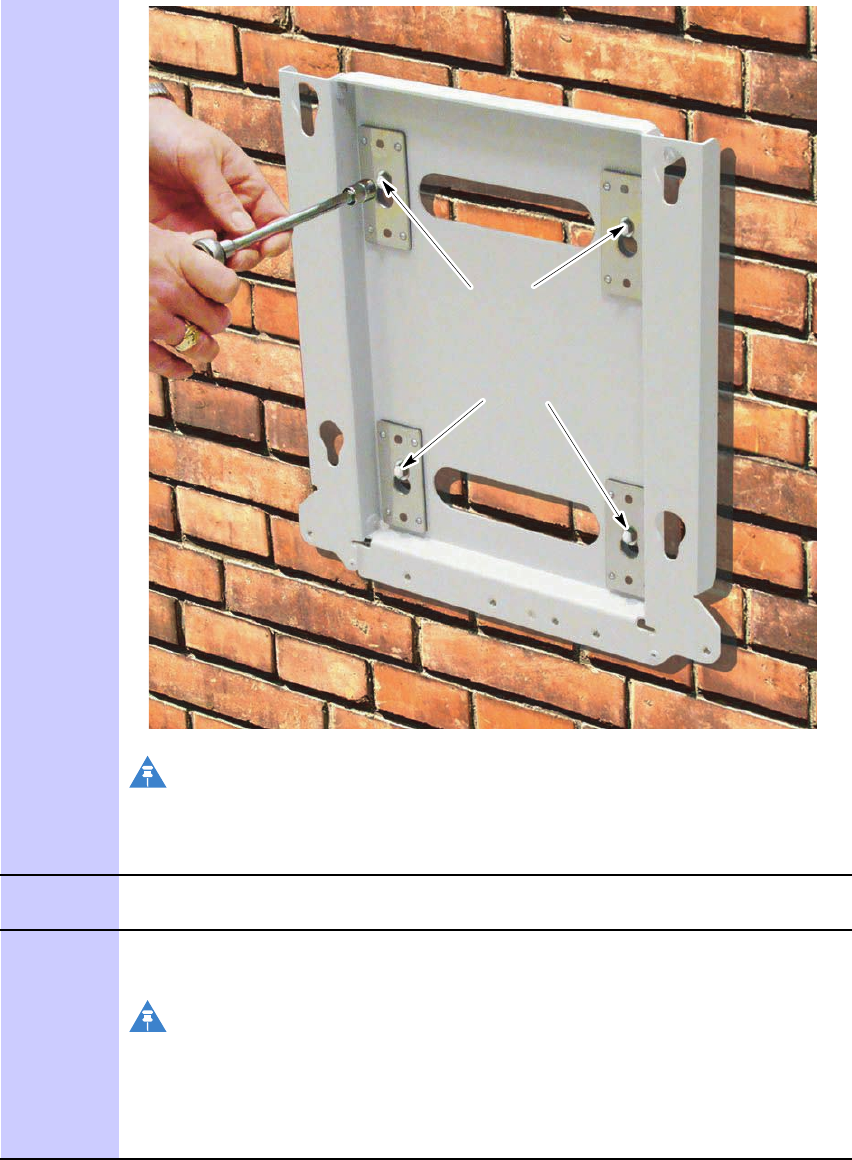
Installingthe700MHzRRHChapter5:InstallationoftheRRH
Procedure5-1700MHzRRHwallmountconguration(Continued)
Step 2
Step 4
NOTE
Ensurethataqualiedstructuralengineerveriesthewall
structureandwall-mountinstallationfortheweightofthe
installationunderadverseconditionsintheinstallationarea.
3Hangthewallmountbracket,insertingthetwoM8boltsintothekeyhole
slots.Slidethebracketintothenallocation.
4InserttwoM8boltsinthebottomtwoslotsandtightenthemusinga13mm
socket.Tightentheinitialtwoboltsinstalledinstep2usinga13mmsocket.
NOTE
Torquesettingforboltsmustcomplywiththevaluerecommended
bythemanufacturerofthewallanchors.
M8x50boltsareprovided.However ,otherfastenersmaybe
necessarypertherecommendationsofthestructuralengineer.
Continued
5-468P09308A55-6
FEB2010
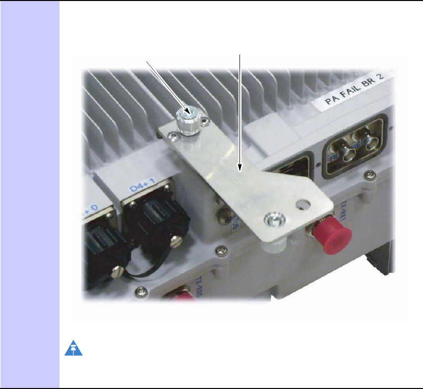
LTEeNodeBIndoorHardwareInstallationInstallingthe700MHzRRH
Procedure5-1700MHzRRHwallmountconguration(Continued)
5Fixthe700MHzsecuringplatetothebackofthe700MHzunit.UsingaT30
securityTorxdriver ,tightenthecaptiveM6fastenertoaminimumtorque
of5.1N-m(45in-lbs).
Captive M6 fastener
RRH Securing Bracket
NOTE
Thesecuringbracketisshippedinthesamepackagingasthewall
mountingbracket.
Continued
68P09308A55-65-5
FEB2010
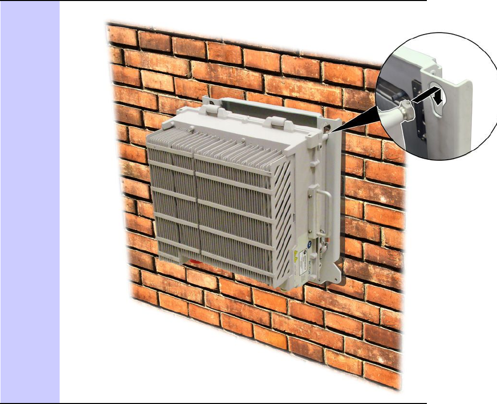
Installingthe700MHzRRHChapter5:InstallationoftheRRH
Procedure5-1700MHzRRHwallmountconguration(Continued)
6InserttheRRHintokeyholesonthebracketusingthemountingfeet.
Continued
5-668P09308A55-6
FEB2010
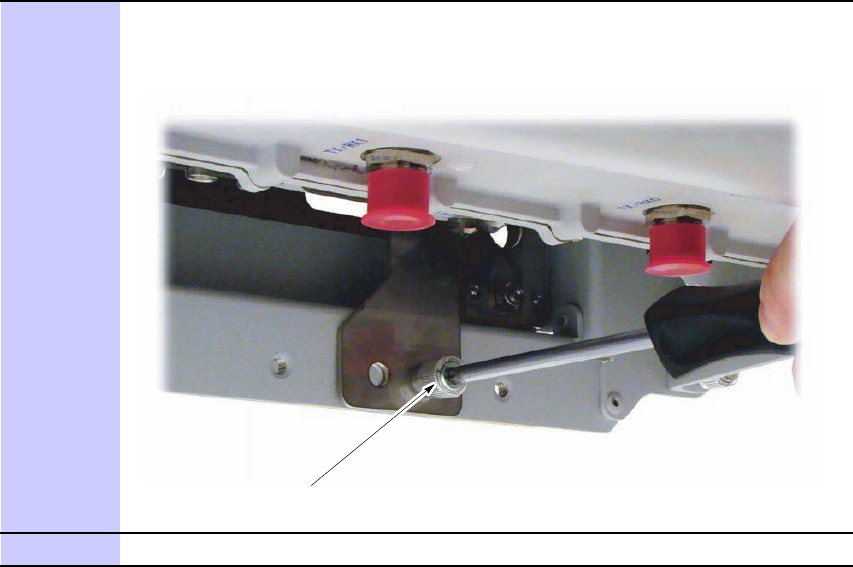
LTEeNodeBIndoorHardwareInstallationInstallingthe700MHzRRH
Procedure5-1700MHzRRHwallmountconguration(Continued)
7Fixthesecuringbrackettothewallmountbracket.Tightenthecaptive
M6fastenerusingaT30securityTORXdrivertoaminimumtorqueof5.1
N-m(45in-lbs).
Captive M6 fastener
8UsingaT25Torxdriver,removethehandlesafterinstallationoftheRRH.
Continued
68P09308A55-65-7
FEB2010
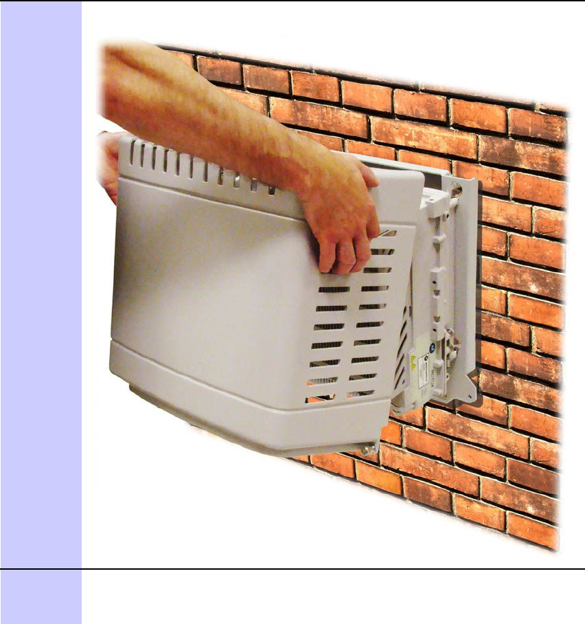
Installingthe700MHzRRHChapter5:InstallationoftheRRH
Procedure5-1700MHzRRHwallmountconguration(Continued)
9FitthesolarcoverbyinsertingthehingesontheRRHintotherecessesinthe
toppanelofthecover .
10SecurethesolarcoverwithM6captivefastenerslocatedineachbottom
corner.TightenthefastenerusingaT30securityTORXdrivertoaminimum
torqueof5.1N-m(45in-lbs).
Continued
5-868P09308A55-6
FEB2010
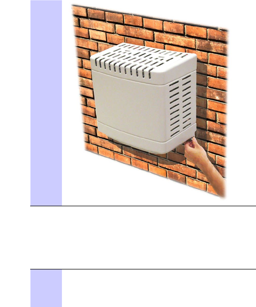
LTEeNodeBIndoorHardwareInstallation700MHzRRHpolemountconguration
Procedure5-1700MHzRRHwallmountconguration(Continued)
700MHzRRHpolemountconguration
Performthefollowingproceduretoinstallthe700MHzRRHtoapole.
Procedure5-2700MHzRRHpolemountconguration
1FixthepolemountingbracketstothepolewithU-boltsorbandingstraps.
Ifbandingstrapsareused:
•Installeachpolemountbracketwithasteelstrap.Tightenthesteel
strapswithbandingtools.Followtheinstructionsofthespecied
bandingtoolfromBAND-ITtotightenthesteelstraps.Continued
68P09308A55-65-9
FEB2010
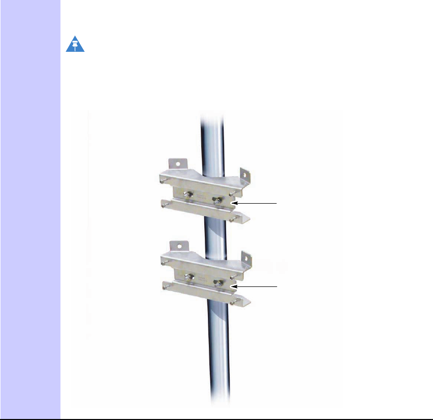
700MHzRRHpolemountcongurationChapter5:InstallationoftheRRH
Procedure5-2700MHzRRHpolemountconguration(Continued)
•MotorolarecommendstheBAND-ITC00169tool.
NOTE
Ensurethataqualiedstructuralengineerveriesthepole
structureandpole-mountinstallationfortheweightofthe
installationunderadverseconditionsintheinstallationarea.
Location for optional band installation
Location for optional band installation
Continued
5-1068P09308A55-6
FEB2010

LTEeNodeBIndoorHardwareInstallation700MHzRRHpolemountconguration
Procedure5-2700MHzRRHpolemountconguration(Continued)
2SecurethepolemountbracketswitheightM6boltstothewallmounting
bracket.Torqueto5.1N-m(45in-lb)usinga10mmsocket.
Continued
68P09308A55-65-11
FEB2010

700MHzRRHpolemountcongurationChapter5:InstallationoftheRRH
Procedure5-2700MHzRRHpolemountconguration(Continued)
3Fixthe700MHzsecuringbrackettothebackofthe700MHzunit.Using
aT30securityTorxdriver ,tightenthecaptiveM6fastenertoaminimum
torqueof5.1N-m(45in-lbs).
Captive M6 fastener
RRH Securing Bracket
NOTE
Thesecuringbracketisshippedinthesamepackagingasthe700
MHzRRHandwallmountbracket.
Continued
5-1268P09308A55-6
FEB2010
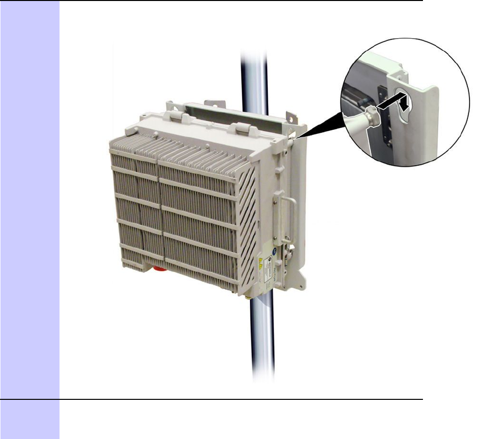
LTEeNodeBIndoorHardwareInstallation700MHzRRHpolemountconguration
Procedure5-2700MHzRRHpolemountconguration(Continued)
4Insertthe700MHzRRHintokeyholesonthebracketusingthemountingfeet.
5Fixthesecuringbracketstothepolemountbracket.Usinga10mmsocket
TORXdriver ,tightentheeightcaptiveM6fastenerstoaminimumtorque
of5.1N-m(45in-lbs).
Continued
68P09308A55-65-13
FEB2010
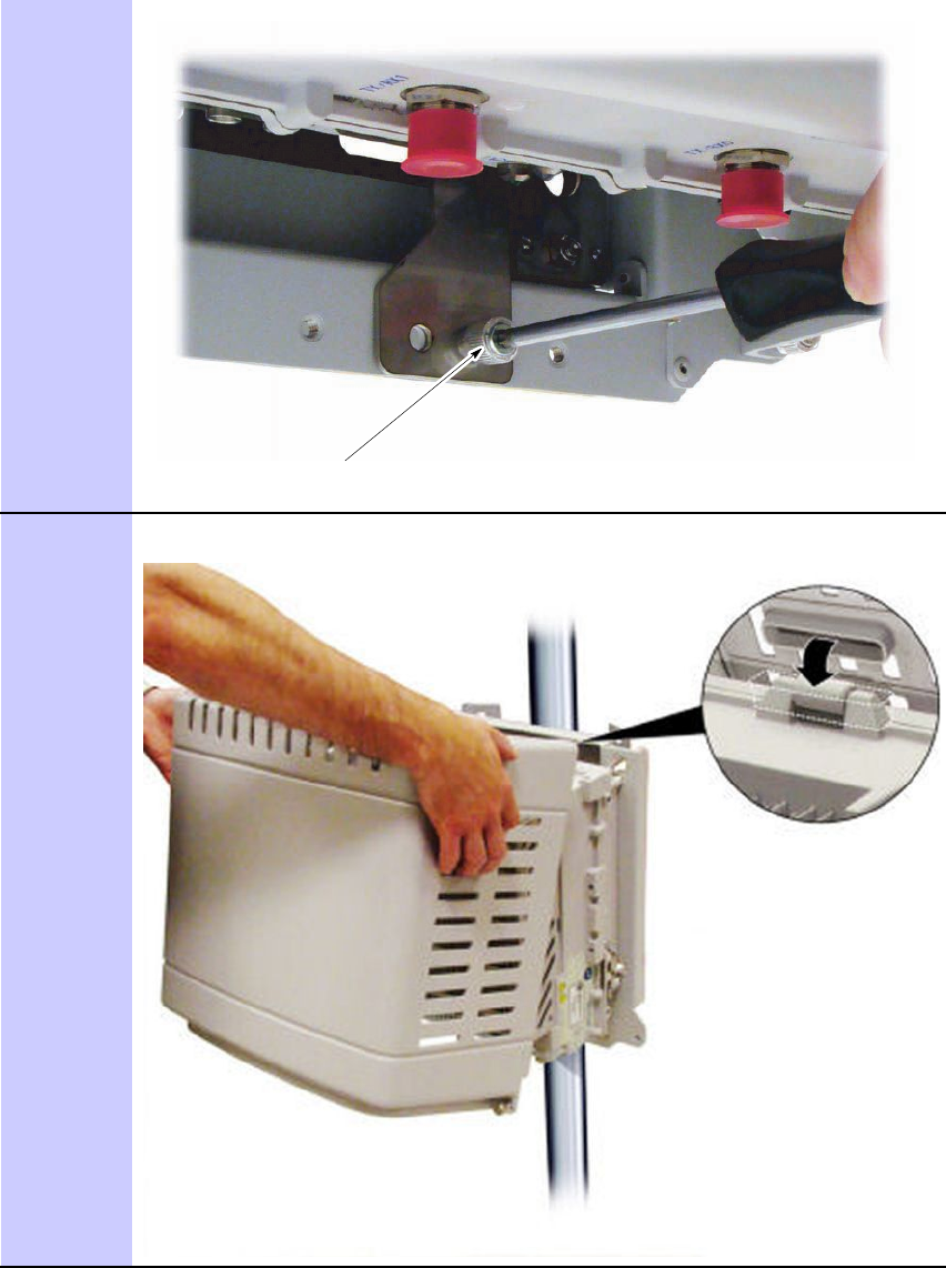
700MHzRRHpolemountcongurationChapter5:InstallationoftheRRH
Procedure5-2700MHzRRHpolemountconguration(Continued)
Captive M6 fastener
6UsingaT25Torxdriver ,removethehandlesonbothsidesoftheRRHafter
installation.
Continued
5-1468P09308A55-6
FEB2010
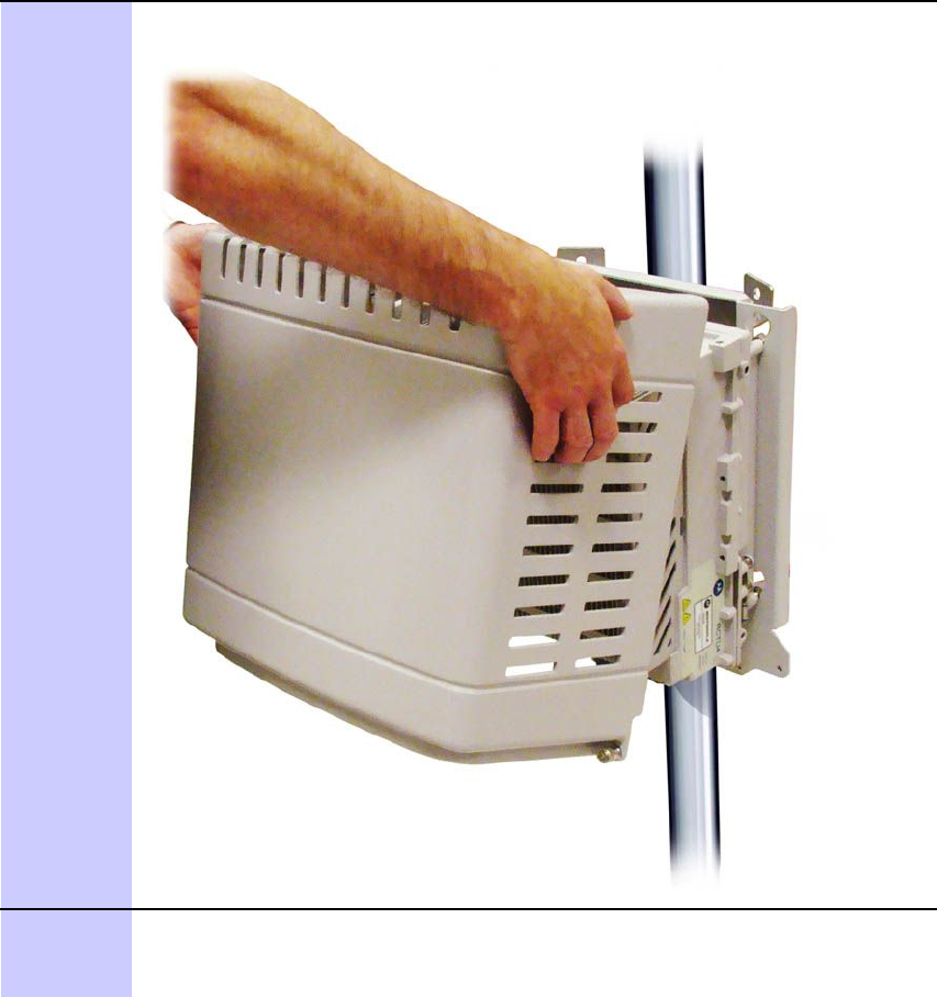
LTEeNodeBIndoorHardwareInstallation700MHzRRHpolemountconguration
Procedure5-2700MHzRRHpolemountconguration(Continued)
7FitthesolarcoverbyinsertingthehingesontheRRHtherecessesinthe
toppanelofthecover .
8SecurethesolarcoverwithM6captivefastenerslocatedineachbottom
corner.TightenthefastenerusingaT30securityTORXdrivertoaminimum
torqueof5.1N-m(45in-lbs).
Continued
68P09308A55-65-15
FEB2010
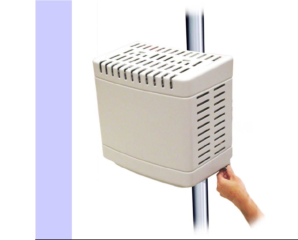
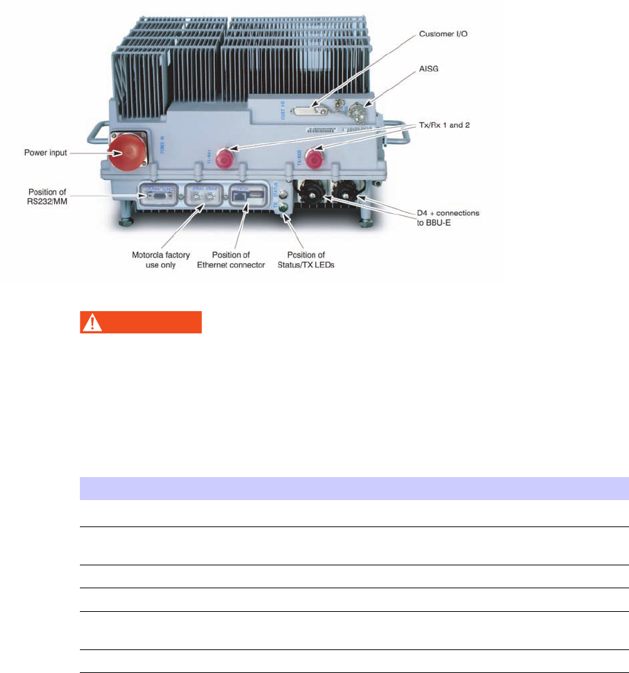
LTEeNodeBIndoorHardwareInstallationInstallationof2.1/2.6GHzRRH
Figure5-1700MHzRRHconnections
WARNING
Thepowerinputconnectionisnotweathersealeduntilthematingcableisinstalled.
Weathersealingisonlymaintainedifthematingcableisinstalledproperly.
AprotectivecovermustbeplacedovertheRS232/factorytimingports/Ethernet
connectorstoensureproperweathersealing.
Table5-1LEDcongurations
StatusLEDTransmitLEDState
SlowFlashingGreenBootstrap(Codeload)state.
GreenActivestandby/call
processingstate.
RedPowerAlarmIndication.
RedRFAlarmIndication.
AlternateFlashing
RedGreen
Flashreprogrammingstate.
YellowRRHistransmitting.
ForcablingrequirementsforRRHproducts,seeeNodeBCableDescriptions(min90Cinsulation
rating)onpage2-13.TheSFPmodulethattsintheD4+socketontheRRHhastobeordered
separately .
Installationof2.1/2.6GHzRRH
Thissectionprovidesprocedurestoinstallthe2.1/2.6GHzRRH.
68P09308A55-65-17
FEB2010

Installationof2.1/2.6GHzRRHChapter5:InstallationoftheRRH
The2.1/2.6GHzRRHcanbeconguredintwoways:
•Wallmountconguration
•Polemountconguration
Thechassisforboth2.1GHzRRHand2.6GHzaresimilar.
Themountingbracketscanaccommodatea2-inchto4.5-inchdiameterpoleorbemounted
directlytoaatwallbyomittingclampsandthreadedrodsandusingfour7/16-inchdiameter
cornerholes.ASecurityTorxT45driverisrequiredtoxtheM8SecurityTorxPanHeadscrew .
PerformthestepsinProcedure5-3toinstallthe2.1/2.6GHzRRHtoawall.
Procedure5-32.1/2.6GHzRRHwallmountconguration
1
CAUTION
Ensurethataqualiedstructuralengineerveriesthewallstructure
andwall-mountinstallationfortheweightoftheinstallationunder
adverseconditionsintheinstallationarea.
Drillfourholesoftheappropriatesizeintothewallforthewallmount
anchorsasrecommendedbythestructuralengineer.Drilltheholesinthe
locationsasshowninFigure5-2.
2Installwallanchorsintothedrilledholes.
3Alignthefourmountingholesinthewallmountbracketwiththefourholes
drilledintothewall,andinstallscrewsthroughthemountingbracketinto
thewallanchorsinstalledinstep1.
4Tightenthefourscrewstothetorquevaluerecommendedbythe
manufacturerofthewallanchors.
5InserttheM8capscrewsintotwouppermountingholesonthesidesofthe
RRH.Engage2to3threadsofeachfastener.
6InserttheRRHintothebracketandsupportbypositioningthethreaded
shanksofthetwopartiallyinstalledM8capscrewsintotheopenslotsat
thetopofthebracket.
7PivotthelowerportionoftheRRHuntilthelowertwomountingholesofthe
bracketalignwiththethreadedlowertwomountingholesatthesidesofthe
RRH.InserttheremainingtwoM8capscrewsandtightento24.3+/–1.3N-m
(18+/-1foot-pounds).TightenthetoptwoM8capscrewsto24.3+/–1.3N-m
(18+/-1foot-pounds).
8Connecttheframegroundcabletothedesignatedpadonthebottom
surfaceofRRHusingthetwo¼-20threadedstuds,lockwashers,andhex
nutsprovidedwiththeRRH.Tightenhexnutsto10.8+/–1.3N-m(8+/-1
foot-pounds).
5-1868P09308A55-6
FEB2010
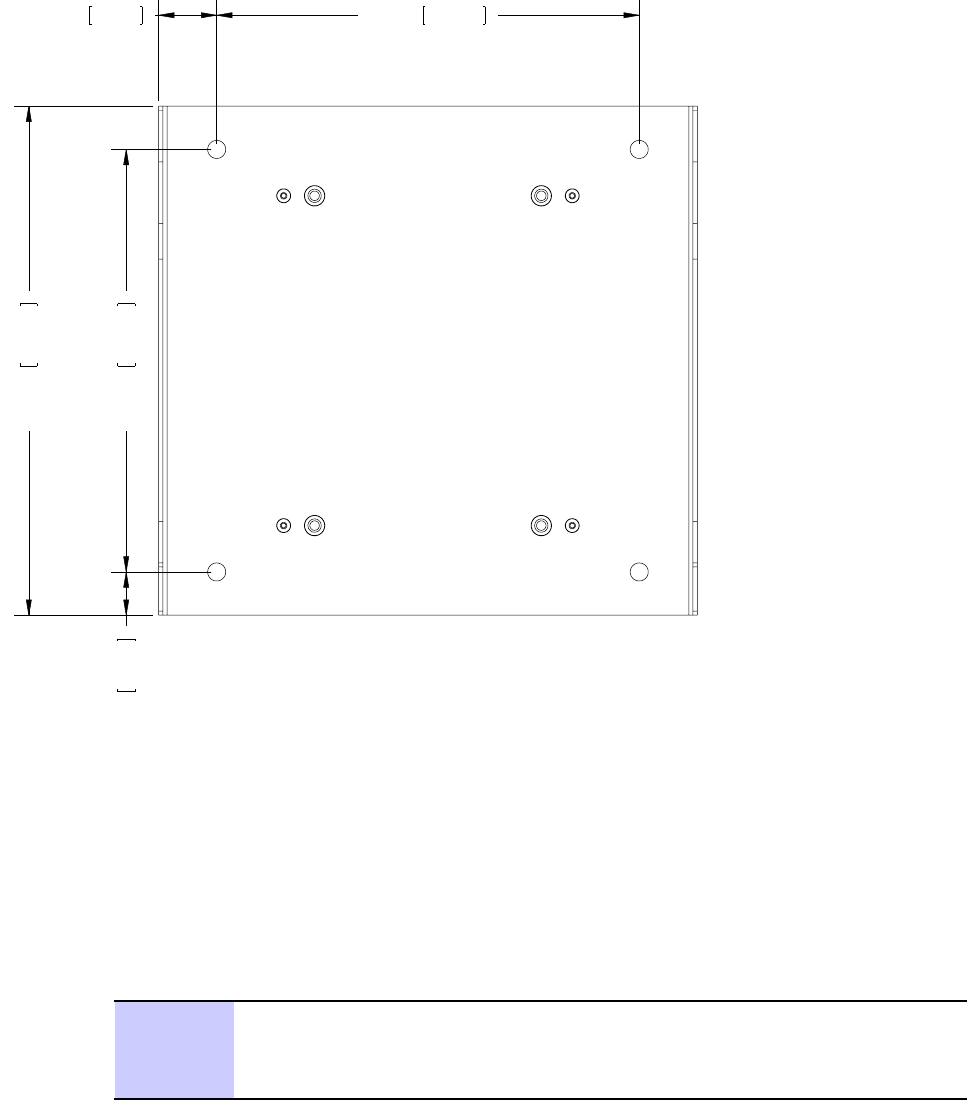
LTEeNodeBIndoorHardwareInstallation2.1/2.6GHzRRHpolemountconguration
Figure5-2LTE2.1/2.6GHzRRHWallMountBracketMountingHoleLocations
053.21
96
.
313
050.176.62 052.01
53
.
062
1.40835.75 10.250
260.35
2.1/2.6GHzRRHpolemountconguration
PerformthestepsinProcedure5-4toinstallthe2.1/2.6GHzRRHtoapole.
Procedure5-42.1/2.6GHzRRHpolemountinstallation
1Attacha50.8mm(2-inch)poleclamptotherearsurfaceofthesupport
bracket.SupportintwolocationsasshowninFigure5-3.FastenwithM5
x12mmlongHexHeadscrewsandtightenedto4.5+/-.22N-m(40+/-2
inch-pounds).
Continued
68P09308A55-65-19
FEB2010

2.1/2.6GHzRRHpolemountcongurationChapter5:InstallationoftheRRH
Procedure5-42.1/2.6GHzRRHpolemountinstallation(Continued)
2InsertfourM8x200mmlongthreadedstudsthroughholesinthepreviously
mountedpoleclamp.Threadintothesupportbracketuntilstudsprotrude
1.524mm-3.175mm(.06-0.1250inches)beyondtheM8clinchnuts.
3Positionthepreviouslyassembledmountingbracketagainsta50.8mm
(2-inchminimum)to114.3mm(4.5-inchmaximum)outsidediameterpole,
sothattheserratedfeaturescapturethepoleandtheM8threadedstuds
straddlethepole.TheassemblymustbeorientedwiththeRRHmounting
slotsfacingupwardasshowninFigure5-3.
4Slidetheremainingpiecesofthe50.8mm(2-inch)poleclampontotheM8
threadedstuds,ontheoppositesideofthepolefromthepreviouslyinstalled
50.8mm(2-inch)poleclamppieces,againcapturingthepolewithinthe
serratedfeaturesofeachpiece.
5InstalltheM8splitlockwasherandtheM8hexnutontoeachM8threaded
stud,andevenlytightento24.3+/–1.3N-m(18+/-1foot-pounds).
6InserttheM8capscrewsintotwouppermountingholesonthesidesofthe
RRH.Engage2to3threadsofeachfastener.
7InserttheRRHintothebracketandsupportbypositioningthethreaded
shanksofthetwopartiallyinstalledM8capscrewsintotheopenslotsat
thetopofthebracket.
8PivotthelowerportionoftheRRHuntilthelowertwomountingholesofthe
bracketalignwiththethreadedlowertwomountingholesatthesidesofthe
RRH.InserttheremainingtwoM8capscrewsandtightento24.3+/–1.3N-m
(18+/-1foot-pounds).TightenthetoptwoM8capscrewsto24.3+/–1.3N-m
(18+/-1foot-pounds).
9Connecttheframegroundcabletothedesignatedpadonthebottom
surfaceofRRHusingthetwo¼-20threadedstuds,lockwashers,andhex
nutsprovidedwiththeRRH.Tightenhexnutsto10.8+/–1.3N-m(8+/-1
foot-pounds).
LTE2.1/2.6GHzRRHMountingBracket
Figure5-3showstheLTE2.1/2.6GHzRRHmountingbracketandFigure5-2illustratesthe
mountingbracketinawallmountcongurationalongwiththenecessarymountinghole
locations.
5-2068P09308A55-6
FEB2010
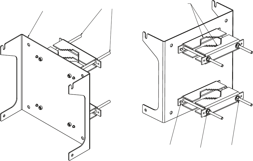
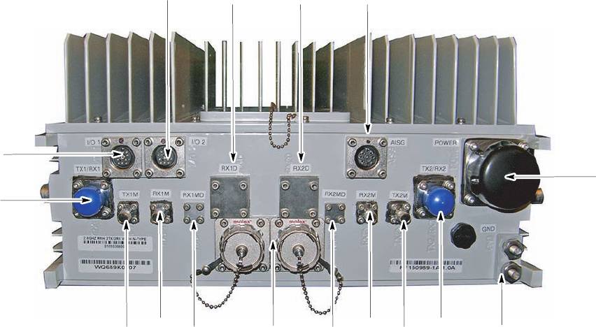
2.1/2.6GHzRRHChapter5:InstallationoftheRRH
Figure5-42.1GHzRRH
E1_radiohd_frt.eps
TX1M 2x MOLEX
RX1D
TX/RX1
I/O 1
I/O 2
RX2MD
RX1M TX2M
RX2M
RX1D RX2D AISG
TX2/RX2
GND
PWR
5-2268P09308A55-6
FEB2010

Chapter
6
CablingoftheRRH
■■■■■■■■■■■■■■■■■■■■■■■■■■■■■■■■■■■■■■■■■■■■■■■■■■■■■■■■■■■■■
■
■
■
■
ThischapterprovidescablinginstructionsfortheRRH,andinterconnectfromtheindoorrack
mountedequipmenttothebuildingI/OpointfortheRemoteRF-BasedeNodeB.
68P09308A55-66-1
FEB2010

Inter-cabling–betweenmajorcomponentsChapter6:CablingoftheRRH
Inter-cabling–betweenmajorcomponents
■■■■■■■■■■■■■■■■■■■■■■■■■■■■■■■■■■■■■■■■■■■■■■■■■■■■■■■■■■■■■
■
■
SafetywhenhandlingFiber/PowerSupplyandEarthCables
HandlingInstructionsforFiberCables
WARNING
Donotlookdirectlyintoberopticcablesordatain/outconnectors.Eitherthedata
in/outconnectorsortheun-terminatedberopticcablesconnectedtodatain/out
connectorscanemitlaserradiation.
Thefollowingspecialhandlingproceduresshouldbefollowedforallbercables:
•Donotremovedustcapsexceptduringoperation.
•Donottouchtheendsurfaceoftheconnectors.Protectitfromdamageatalltimes.If
cleaningisnecessary ,useisopropylalcoholandacleaningtissueonly .
•Makeconnectionscarefullyandslowly ,beingsuretonotetheanti-rotationkeyifapplicable.
•Whenbending,beawareoftheminimumbendradiusallowed.Donotkinkorsqueeze
thecable.
•Preventthecablefromtwisting.Becarefulwhenunwinding.
Safetywheninstallingthepowersupplyandearthcables
WARNING
Observethefollowingpowersupplyandearthcablespre-installationwarnings:
•EnsureacompleteprimaryearthpathbyconnectingtheearthcabletotheRRH
beforeconnectingthepowersupplycabletothemainpowersource.
•Selecttheearthcableratingsinaccordancewiththenationalandregionalwiring
regulations.
•Ensurethattheenclosureearthcableisa6AWG.
•RRHequipmentoperatesatpotentiallyhazardousvoltages.Ensureonlytrained
andcompetentpersonnelworkonthisequipmentinaccordancewiththelocal
regulations.
•Exercisecautionwheninstalling,commissioning,andremovingtheprotective
coversforanypurpose.
•Avoidwearingantistaticwriststrapwhileservicingthepowersuppliesorpower
distributioncablingtopreventseriouspersonalinjury.
6-268P09308A55-6
FEB2010

LTEeNodeBIndoorHardwareInstallationRRHgoundconnections
RRHgoundconnections
PerformthefollowingproceduretoconnectRRHtoground.
Procedure6-1ConnectingRRHtoground
1UsingaT30securityTorxdriver,loosenandremovetheearthgroundlug
ontheRRH.
2Obtaina6AWGearthcablefortheRRHearthlugandremovetheouter
sheathtoexposethecorrectlengthofthebarecopper.
3ReattachthegroundlugontotheRRH.UsingaT30securityTorxdriver,
tightenthecaptivescrewsto5.1N-m(45in-lbs).
4Connecttheoppositeendoftheearthcabletoaneffectiveearthingpoint.
RRHpowerconnections
ThissectioncontainstheprocedureforconnectingtheRRHpowercables.
RRHpowerconnectionconsiderations
NOTE
Alwayscheckwiththelocalbuildingauthoritiesforthewiresizerequirementsfor
yourenvironment.
NOTE
WheninterfacingwiththeBCUII,thecustomerisresponsibleforprovidingdcpower
totheRRH.Thefollowinginformationisareminderofthecustomersresponsibilities.
Thecustomerisultimatelyresponsibletoensurethatallgroundingguidelinesand
customer-suppliedPowerCabinetorservicebayconnectionsmeetlocalelectrical
codes.
Consultthesiteplanningdocumentstodetermineifthewirecolorshavebeenpreviously
specied.Consultthe
Standards and Guidelines for Communication Site, Motorola part number
68P81089E50
forfurtherpowercablinginformation.
Ifthedcpowercablelengthbetweenthecustomer-suppliedPowerCabinetorservicebay
andtheRRHexceeds3meters,verifythatthepowersourcemeetsConductedEmissions
requirementsfromETSIEN301489-1Clause8.3DCPowerInputandOutputPorts.This
actionistomaintaintheregulatorytypeapprovalrequirementforthosemarketsrequiringa
CEmarkontheequipment.
68P09308A55-66-3
FEB2010
RRHpowerconnectionsChapter6:CablingoftheRRH
RRHexternalpowersupply
Propersafeguardsmustbeinplacetoinsurecompliancewithregulatoryspecicationsforthe
regionoftheinstall.TwoareasofconcernareElectromagneticInterference(EMI)andSurge
protection.
Surgeprotectionofthedcoutput
Thespecicationsforsurgeprotectionare:
•MustbecomplianttoIEC61000-4-5,ClassX5KVat2.5KACommonModeand500Vat
250ADifferentialModeIECcombinedwaveform.
•Physicallylocatetheprotectionunitascloseaspossibletowherethedclinecomesinto
thestructure.
•MustmeetelectrostaticdischargeperIEC61000–4–2Level4.
Motorolarecommendedsurgeprotectors:
•Transtector,partnumber12RICP
•EmersonPower ,partnumberDCB-48
Onesurgeprotectorisusedforeachsector .
DCpowerlter(EMIprotection)
ThespecicationsfortheDCpowerlterare:
•LimitsfortheconducteddisturbanceatthemainsportsofClassBITEequipmentmeetthe
limitsspeciedinEN55022:2006(derivedfromCISPR22:2005)
•DCseries,15Ato125A
•General-purposeapplication
•Supportsbulkheadandrackmounting
Motorolarecommendsthefollowingpowerlter:
•TycoElectronics(CORCOM),partnumber10VN1(6609052–2)
Onepowerlterisusedforeachsector.
RRHdcpowercableconnection
Thefollowingprocedureassumes:
•ThecustomerisusingtheMotorolasuppliedRRHdcpowercables.
•TheDCPowerFilterandtheDCSurgeSuppressorunitsarelocatedinsidethecustomer
location.
•TheDCPowerFilterandtheDCSurgeSuppressorunitsarealreadyinstalledandcabled.
6-468P09308A55-6
FEB2010
LTEeNodeBIndoorHardwareInstallationRRHpowerconnections
RefertoFigure6-3forthelocationofthepowerconnectorontheRRHs.Therecanbetwo
methodsofsupplyingpowertotheBCUIIandRRH:
•Twoseparatepowersourcesareused.OnefortheBCUII(-48Vdc)andonefortheRRH
(+54Vdc).
•Asinglepowersource(-48Vdc)suppliespowertoboththeBCUII(-48Vdc)andtheRRH
(+54Vdc).Thepolaritymustbereversedwhenconnectingthecablestotheheadto
convertthepowersourceto+54Vdc.RefertoFigure6-1foragenericsystempower
cablingdiagramofthismethod.
68P09308A55-66-5
FEB2010

RRHpowerconnectionsChapter6:CablingoftheRRH
Figure6-1SystemPowerCabling
E1_SysPwrCabling1.eps
RACK
MGB Rack
Customer
Supplied
Customer
Supplied
Customer
Power
+27 V
PDU
+27 V Radio Shelf
Radio Shelf
Radio Shelf
BCU
AE
AC
AC
AC
AL
AL
**
** When using a Motorola rack, only the BCU and the frame need to be cabled to the MGB.
When using a non-Motorola rack, all items must be cabled to the MGB.
RRH STYLE 1
MGB
Customer
Supplied
Customer
Supplied
Customer
Power
-48 V
PDU
-48 V
RRH
RRH
RRH
BCU Surge suppressors
and filters *
Building
Entrance/Exit
AE
AK
AK
AK
AB
AB
AB
AL
AL
* Surge suppressors and filters are customer supplied.
MGB = Master Ground Bus
RRH STYLE 2
MGB
Customer
Supplied
Customer
Supplied
Customer
Power
-48 V RRH
RRH
RRH
BCU
Surge suppressors
and filters *
Building
Entrance/Exit
AB
AB
AB
AL
* Surge suppressors and filters are customer supplied.
MGB - Master Ground Bus
6-668P09308A55-6
FEB2010
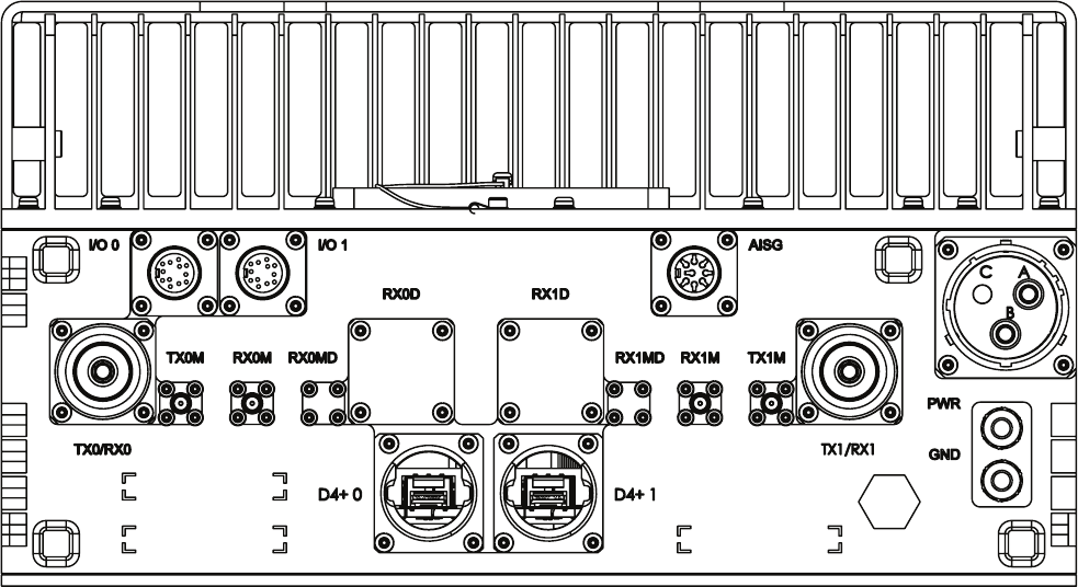
LTEeNodeBIndoorHardwareInstallationRRHpowerconnections
Figure6-22.6GHzRRHconnections
68P09308A55-66-7
FEB2010
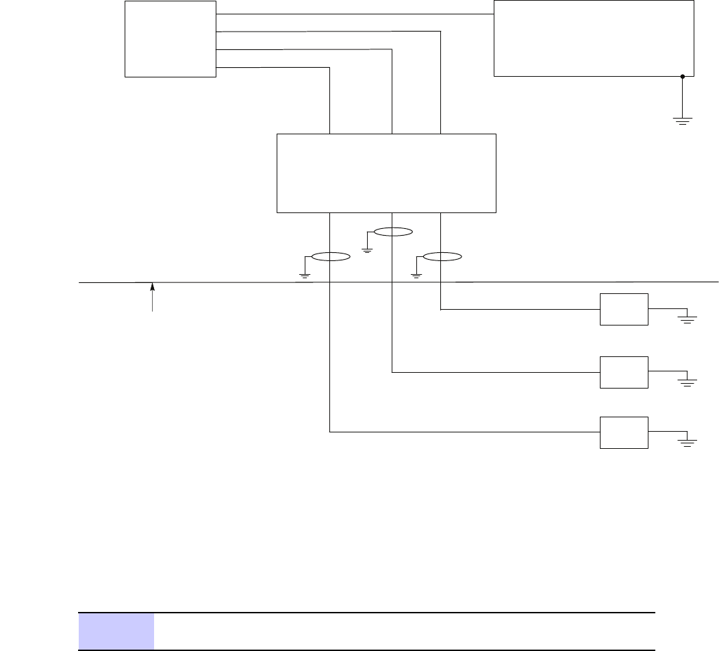
RRHpowerconnectionsChapter6:CablingoftheRRH
Figure6-3RRHpowercabling
E1_Head_IndoorBCUII_PWR1.eps
Site DC Power
or
Motorola PDU
Transmission Entry Point
(Building Entrance/Exit)
Note: Head is designed to use -48 V dc.
EMI Filter and Surge Protector are customer supplied.
BCU
RRH
RRH
RRH
It is a good practice to ground the
cables at the building entrance using
cable clamps. The power cable
includes a ground braid for this purpose.
Cable clamps are customer supplied
and need to support a 9 mm cable.
Surge Protection and
DC Filters - as required
Procedure6-2RRHpowercabling
1Ensurethatcustomersupplieddcpowersource(+54Vdcor–48Vdc)is
disengaged.
Continued
6-868P09308A55-6
FEB2010

LTEeNodeBIndoorHardwareInstallationRRHpowerconnections
Procedure6-2RRHpowercabling(Continued)
2Beforeroutingthedcpowercable,verifythatitisproperlycolorcoded.If
morethanoneRRHisinuse,ensurethattheyareallproperlycolorcoded.
Thecolorsareasfollows:
•RFU1–RED
•RFU2–BLUE
•RFU3–YELLOW
•RFU4–GREEN
PlaceacorrespondingcoloredadhesivebackedlabelontheRRH(1-4)chassis
inthearealabeledRFUID.
3Atthecustomerlocation,locatetheterminalblockwhichsuppliespower
totheheads.
4Ensurethatthereisenoughcableinsidethecustomerlocationsothat:
•TheRedwireofthecablecanconnecttotheDCSurgeSuppressor.
•TheBlackwirecanconnecttotheterminalblock.
5Atthetransmissionentrypoint(customerbuildingexit/entrance),ground
thecablesby:
•Strippingthepowercableofitsouterjackettoexposetheshieldand
innerconductors.
•Stripbacktheshieldtoalengthsuchthatitcanbeproperlygrounded
usingacableclamp.
Securelyclamptheoutercablejacketwithenoughlengthforthepower
conductorstoreachthecorrectterminalblockandtheDCSurgeSuppressor
withoutexcessivestrain.Ensurethatthereispropergroundingbetweenthe
shield,braid,andgroundingcontactsofthecableclamp.
6Terminatethepowerconductorswithferrules(PN2987529D01)@2Xusing
thepropercrimptool(TycoP/N47387-7).Ensurethattherearenoloose
strandsthatmightcomeincontactwithametallicsurface,tool,orother
conductor.
Continued
68P09308A55-66-9
FEB2010

RRHtoBCUIIinterconnectChapter6:CablingoftheRRH
Procedure6-2RRHpowercabling(Continued)
7ConnecttheBlackcabletotheterminalblock.ConnecttheRedcabletothe
DCSurgeSuppressor .Tightentheconnectors.
CAUTION
•Ensurethattheferrulesdonotcontacteachother ,other
metallicstructure,tools,oranyotherconductivemediaafter
nalinstallation.Caremustbetakentoensurethatthecircuit
isisolatedandcomplete.
•DonotengagetheRRHCircuitBreakersuntilacompleteand
properconnectionhasbeenmadeattheRRHendofthe
conductor ,andtheRRHisinitsnalmountedposition.
•Donotovertorquetheterminalblockofthecustomersupplied
powerwhentighteningthecableconnections.Thecustomer
suppliedpowerterminalblockmustnottwist.
8Routethepowercableupthepoletotheappropriateheads.Groundthecable
alongitslengthusingtheshieldandbraidofthecableforgroundconnection
tothetowerstructureorothermaingroundpointorstructure.
Ifconduitisbeingused,routethepowercablesthroughtheconduit.
9ConnectthepowercabletothedcinputconnectorontheRRH.Tie-wrap
cableasnecessary .Ensurethatthereissufcientstrainrelief.
RRHtoBCUIIinterconnect
PerformthestepsinProcedure6-3toconnectthedigitalcabletotheBCUII.
Procedure6-3ConnectingthedigitalcabletotheBCUII
1OpentheBCUIIfrontdoorandinstallonebertransceivermoduleperRadio
intotheBCUII,startingwithSFPportA.
NOTE
TheSFPslotsarelabeledA,B,C,andD.PopulateSlotArst.
2UsingaT20Torxbit,removetwoscrewstoremovethebercablefeed
throughplatefromtheleftinsidewalloftheBCUII.
NOTE
Thefeedthroughplatemayalreadybeoffpertheprevious
procedurestoinstalltheBCUIIintherack.
3Positionthecablesuchthatthecableisinthelowestpositionandthatthe
grommetisinthelocationindicatedinFigure6-4.
Continued
6-1068P09308A55-6
FEB2010
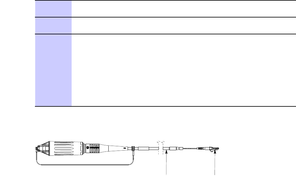
LTEeNodeBIndoorHardwareInstallationRRHtoBCUIIinterconnect
Procedure6-3ConnectingthedigitalcabletotheBCUII(Continued)
4Removetheprotectivecapsfromthebercableconnectorandtheber
transceivermodule.
5Matethebercabletotheleft-mostbertransceiver ,whichismarkedA
underthebertransceivermodule.
Repeatstep1–step5forthesecondandthirdbercableuntiltheyare
routedasshowninFigure6-6andFigure6-7.
6
Connectthesecondandthirdbercablesasfollows:
•Secondbercable–Connecttothesecondgrommet,positionupand
matetobertransceiverB.
•Thirdbercable–Connecttothethirdgrommet,positionupandmate
tobertransceiverC.
GrommetlocationsareshowninFigure6-5
Figure6-4FiberCable
E1_XCR_cable.eps
Grommet
Location
BCU II
Connection
68P09308A55-66-11
FEB2010
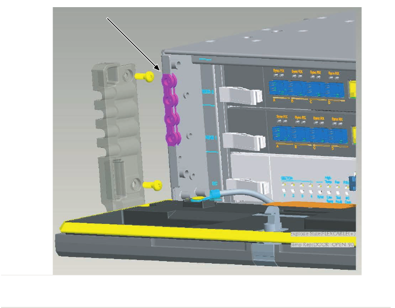
RRHtoBCUIIinterconnectChapter6:CablingoftheRRH
Figure6-5BCUIIFiberOpticCableGrommetLocation
GROMMET
D2_BCUII_Grommet_Location.eps
6-1268P09308A55-6
FEB2010
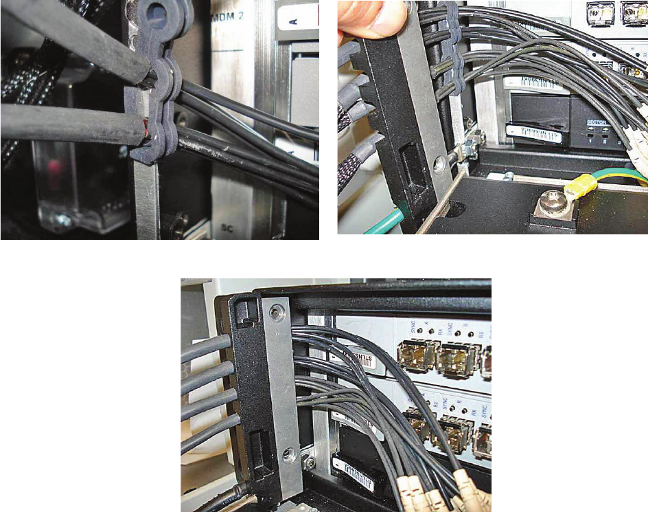
LTEeNodeBIndoorHardwareInstallationRRHtoBCUIIinterconnect
Figure6-6FiberOpticCableBrackets
D2_BCUII_FO_Clip_1.eps
View A View B
View C
68P09308A55-66-13
FEB2010
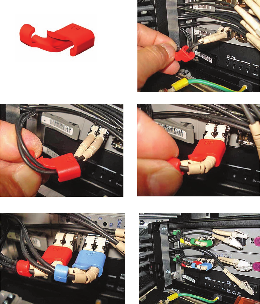

LTEeNodeBIndoorHardwareInstallationRRHtoBCUIIinterconnect
Table6-1Fibercablesrouting
BCUIIbertransceiverRadiobertransceiver
ARRHsector1
BRRHsector2
CRRHsector3
DNone
PerformthestepsinProcedure6-4toconnectthedigitalcabletotheRRH.
Procedure6-4ConnectingthedigitalcabletotheRRH
1
WARNING
Checkthatthedcpowerhasnotbeenconnectedorisolatethedc
powerbeforecommencingthefollowingprocedure.
RoutethebercableoutofthebuildingandtotheRRHsasfollows:
1.FitonesuppliedferriteclipoverapairofD4+cables,insidethecable
entrybox,connectingtotheT43module.
EnsurealltheD4+cablepairshaveoneferritecliptted.
2.FeedtheBCUIIcableendsupthroughthecableglandattherearof
thecabinet.
3.Routethecablesupinsidetherearoftherackandacrossthetopfrom
reartofrontuntiltheyappearatthefrontjustabovetheBCUIIcard.
4.InsertSFPbertransceivermodulesintotheBCUII(followstep2).
ConnecttheberLCconnectortotheSFPbertransceivermodule.
2InstalltheRRHD4+cableasfollows:
1.RemovetheprotectivecoversfromtheD4+socketsontheRRH.
2.UnpacktheSFPbertransceivermodulesandinsertthemintotheD4+
connectors.
3.SecuretheSFPbertransceivermodulesbypushingthemrmlyhome
intothesocketstakingcarenottodamagetheextractionhandle.
TheextractionhandlemustbefoldedagainstthebodyoftheSFPber
transceivermodulebeforetheD4+cablecanbetted.
Continued
68P09308A55-66-15
FEB2010

InstallingRFcablesfromantennastoRRHChapter6:CablingoftheRRH
Procedure6-4ConnectingthedigitalcabletotheRRH(Continued)
CAUTION
•FailuretoensurethattheSFP
bertransceivermoduleisinserted
correctlyandmatedmightresultina
connectionfailure.
•TheD4+cablecanbesecured
intopositioneveniftheSFPber
transceivermoduleisnotfully
inserted,whichresultsinwhatlooks
likearmconnectionexternallybut
internallynoconnectionismade.
4.Withtheberconnectorheldoutoftheway ,insertthetwocablelatches
tothesocket.
5.Holdingtheberconnector,removethetwosmallprotectivecapsand
inserttheconnectorintotheSFPbertransceivermodule.
6.EnsurethatthebercableisfullylatchedintotheSFPbertransceiver
module.
7.Movethecablehousingforwardtocovertheberconnectionandsecure
intopositionbyscrewingithand-tightontothesocket.
InstallingRFcablesfromantennastoRRH
PerformthestepsinProcedure6-5toinstallRFcablesfromantennastoRRH.
Procedure6-5InstallingRFcablesfromantennastoRRH
1RemovetheprotectivecoversfromtheTX/RX0andTX/RX1portsontheRRH.
2ConnecttheRFantennacablestotheTX/RX0andTX/RX1N-typeconnectors
ontheRRH.Usinga19mmtorquewrench,tightentheN-typeconnections
to4.3N-m(38in-lbs).
3SecuretheRFcablesconnectingtheRRHtotheantennausingcabletiesas
appropriatetoreducethechanceofdamagetothecables.
CustomerI/Ocableinstallation
CableAB,listedinTable2-4,isrequiredforthisinstallation.Performthefollowingstepsto
installtheCustomerI/Ocable.
6-1668P09308A55-6
FEB2010

LTEeNodeBIndoorHardwareInstallationEthernetcableinstallation
Procedure6-6InstallingCustomerI/Ocable
1InstalltheCustomerI/Ocable(AB)tothefrontpaneloftheBCUII.
2RoutetheoppositeendoftheCustomerI/Ocabletothetermination
equipment.
Securethecablewithappropriatestrainreliefusingthetiewrapsas
necessary .
3
Ensurethattheberopticandearthgroundcablesareinstalledandthe
BCUIIfrontpanelislatchedproperly .
Ethernetcableinstallation
Ethernetports
TheEthernetportsfortheBCUIIarelocatedonthefrontpanel.Therearethreeportsavailable:
•ENET-A
•ENET-B
•Cust.ENET
TheEthernetportsareusedasfollows:
•Non-redundantEthernetBackhaul(BH)-thetypicalconnectionistoENETA,butENET
Bcanbeused.
•RedundantEthernetBackhaul-thetypicalconnectionistheprimaryBHtoENETAand
redundanttoENETB.RedundantBHisnotsupportedatthistime.
•EthernetBackhaulDiagnostics-thetypicalconnectiontoENETAorENETBisalocal
computerwithEthernettrace(Wireshark).Thisallowsbackhaultrafctobemonitored
ortested.
•CustomerENET-AllowsaccesstothebackhaulwhentheENETAandBportsarebeing
used.
Ethernetcableinstallation
CableAG,listedinTable2-4isrequiredforthisinstallation.PerformthestepsinProcedure6-7
toinstalltheEthernetcable.
Procedure6-7InstallingtheEthernetcable
1OpenthepackagecontainingtheEthernetcables.
Continued
68P09308A55-66-17
FEB2010

EthernetcableinstallationChapter6:CablingoftheRRH
Procedure6-7InstallingtheEthernetcable(Continued)
2ConnecttheEthernetcablestotheEthernetportsENET -AandENET -Bon
theBCUIIfrontpanel.
RoutetheoppositeendtotheRouter .Therouterprovidesadditionalprimary
surgeprotection.
3
Securethecableswithappropriatestrainreliefusingthetiewrapsas
necessary .Ensurethattheberopticandearthgroundcablesareinstalled
andthefrontpanelislatchedproperly .
6-1868P09308A55-6
FEB2010

LTEeNodeBIndoorHardwareInstallationRRHhead–48Vdcpowercablinginstallation
RRHhead–48Vdcpowercablinginstallation
■■■■■■■■■■■■■■■■■■■■■■■■■■■■■■■■■■■■■■■■■■■■■■■■■■■■■■■■■■■■■
■
■
ThissectioncontainstheprocedureforinstallingtheRRHhead–48Vdcpowercables.
RRH–48VdcpowerwhenusingaBCUII
WheninterfacingwiththeBCUII,thecustomerisresponsibleforprovidingdcpowertothe
RRH.ThecustomerhastheoptionofusingtheMotorola–48VPDUorprovidingtheirown
PDUfunction.Thefollowinginformationisareminderofthecustomersresponsibilities.The
customerisultimatelyresponsibletoensurethatallgroundingguidelinesandCustomer
SuppliedPowerCabinetorservicebayconnectionsmeetlocalelectricalcodes.Thefollowing
procedureassumesthatthecustomerisusingtheMotorolasuppliedRRHdcpowercables.
IfthedcpowercablelengthbetweentheCustomerSuppliedPowerCabinetorservicebay
andtheRRHexceeds3meters,verifythatthepowersourcemeetsConductedEmissions
requirementsfromETSIEN301489-1Clause8.3DCPowerInputandOutputPorts.This
vericationistomaintaintheregulatorytypeapprovalrequirementforthosemarketsrequiring
aCEmarkontheequipment.
Propersafeguardsmustbeinplacetoinsurecompliancewithregulatoryspecicationsforthe
regionoftheinstall.TwoareasofconcernareElectromagneticInterference(EMI)andSurge
protection.
Circuitbreakerfordcoutputtohead
ForcircuitbreakerandwiregaugerequirementsforRRHproducts,seeDCsupplyequipment,
Maincircuitbreaker ,andDCinputcableonpage2-7.
Connecting–48VdcPower
TheConnecting–48VdcPowersectionprovidesthefollowinginformationonroutingtheloose
endsofthewirestothesite–48Vdcsourceforconnectiontothesource.
Tominimizecurrentimbalancebetweenthefeed(-V)andreturn(+V)wiresusedinthecable,
ensurethatthewiresize,length,andgaugeofeachwireusedinthecablearethesame.
NOTE
ThissectionappliesforsiteswithoptionalMotorola-providedPDUonly .
68P09308A55-66-19
FEB2010

Connecting–48VdcPowerChapter6:CablingoftheRRH
Requiredmaterialsandtools
Thefollowingmaterialsandtoolsarerequired:
•One–48VdcPowerInputCable-customersupplied.
•Wirestripper/cutters.
•DigitalMulti-Meter(DMM)FlukeModel8062AwithY8134testleadkitorequivalent;used
forprecisionDCandACmeasurements,requiring4-1/2digits.
Powercablingandtiedownrequirements
TocontroltheinductanceattheEnodeBDCpowerinputduetothespacingbetweenwiresused
inthe–48VdcPowerInputCable(DC),bindthefeed(-V)andreturn(+V)wirestogether
atintervalsofonemeterorless.
Connecting–48Vdcpowertothe–48VdcLTEEnodeB.
PerformthestepsinProcedure6-8toconnect–48Vdcpowertothe–48VdcLTEEnodeB.
WARNING
•Donotwearawriststrapwhenservicingthepowersuppliesorpowerdistribution
cabling.
•EnsurethatthesourcefortheDCpowerisintheOFFposition.
•EnsurethatallthePDUcircuitbreakersareOFF .
Forthe–48VdcRemoteRFbasedeNodeBLTEsystem,thecustomerhastheoptionofusingthe
Motorola-provided–48VdcPDUortheirowncircuitbreakers.IftheMotorola—providedPDUis
used,performthestepsinProcedure6-8toinstallandconnectthePDU.WireAWG/breaker
informationisprovidedWireAWG(min90Cinsulationrating)andcircuitbreakersizingfor–48
VDCRRHsystemswithoutPDUoption(customer-providedPDUfunction)onpage2-9.
Procedure6-8Connecting–48VdcPower
1EnsurethatthegroundcableisconnectedbetweentherackandtheMaster
GroundBar.
2Ensurethatthe–48VdcPowerInputCableisnotconnectedtothemain–48
Vdcpowersource.Turnoffthemain–48Vdcpowersource.Conrmthat
thepowerisswitchedOFFusingaDVM.
3ThePDUissuppliedwith2-Holecrimponlugsfor1/0AWGstandardor2
AWGhigh-strandcountexcable.Ifyourequireanothertypeofcable,order
newlugsasneeded.EnsurethatthelugsmeetthecriteriainTable3-2.
Continued
6-2068P09308A55-6
FEB2010
LTEeNodeBIndoorHardwareInstallationConnecting–48VdcPower
Procedure6-8Connecting–48VdcPower(Continued)
NOTE
Theexpectedloadconditionandcablelengthdeterminesthewire
gagerequiredforthesystem.SeeTable2-2.
4Removethelugcoverandservicecoverusingtheirrespectivesnaps.
5Insertthetwo-holelugsthroughtherearofthePDU,sothattheholesinthe
lugsalignwiththeholesinthelugmountingplates.
6InstalltwoM6atwashersandtwoM6x16screwsintoeachlug(4washers
and4nutstotalforthe2lugs)usingaT30Torxdriver.
NOTE
Theatwashersandscrewsaresuppliedinthebagsziptiedtothe
PDUrearbracket.
Leavethescrewsloosesothatthelugscanbeadjustedside-to-side.
7Replacethelugcoverwhileadjustingthecablestoensurethatthecover
canbesnappedintoposition.
8Tightenthelugscrewsto5.1N-m(45in-lb)andreplacetheservicecover.
9Installziptiesaroundthecablesthroughtherearbracketandpulltightfor
sufcientstrainrelief.
10Connecttheotherendofthe–48Vdcpowerandreturnwirestothepower
source.
NOTE
Donotturnonthepowersourceatthistime.Thismustbedone
aftertheinstallationandcablingiscomplete.
Table6-2Lugcriteria
PDUinputLTEPDUinput
labeltext
Crimplug'scenter–to
–centerspacingofM6
(1/4”)screwholes
Wiregagecompatibilityfor
suppliedlugs
–48Vdc(blue
arrow)
19mm(3/4inch)
–48Vdc
0V(blackarrow)16mm(5/8inch)
GroundFrameground16mm(5/8inch)
1/0standardcable
68P09308A55-66-21
FEB2010
CablingofRRHChapter6:CablingoftheRRH
CablingofRRH
■■■■■■■■■■■■■■■■■■■■■■■■■■■■■■■■■■■■■■■■■■■■■■■■■■■■■■■■■■■■■
■
■
2.1/2.6GHzRRH
Chassismountinghardware
Thechassisforboth2.1GHzRRHand2.6GHzaresimilar.
Thechassisgroundinglocationisadoublestud/hexnut.Theinstallersuppliesthelug.Panduit
hasdouble1/4–inchhole5/8–inchspacingcompressionlugsthathandlewiresrangingfrom
2/0to8AWG.
Connectortypes
Followingaretheconnectortypesusedonthe2.1GHzRRH,2.6GHzRRH,andmounting
bracket:
•I/01andI/02—12PinCircularFemale
•AISG—eightPinCircularFemale
•Power—2pinconnectorMale
•TX1/RX1andTX2/RX2—N-TypeFemaleon2.1GHzand7/16connectorson2.6GHz
•TX1M,RX1M,TX2M,andRX2—SMAFemale
ConnectingpowerandtheRFtotheRRH
ForinstructionstoconnectpowerandtheRFtotheRRH,seeProcedure6-2.Forinstructionto
connectRFcablesfromantennastotheRRH,seeProcedure6-5
6-2268P09308A55-6
FEB2010

Chapter
7
Power-upsequence
■■■■■■■■■■■■■■■■■■■■■■■■■■■■■■■■■■■■■■■■■■■■■■■■■■■■■■■■■■■■■
■
■
■
■
Thischapterprovidesthepower-upsequencefortheeNodeB.
68P09308A55-67-1
FEB2010

PowerUpSequenceChapter7:Power-upsequence
PowerUpSequence
■■■■■■■■■■■■■■■■■■■■■■■■■■■■■■■■■■■■■■■■■■■■■■■■■■■■■■■■■■■■■
■
■
Procedure7-1PowerUpSequence
1Turnonthecircuitbreakerforthecustomersuppliedpower.
2ClosetheeNodeBmaindisconnectcircuitbreakerontheexternalpower
feedtopowerthePDU.
3IfaMotorolaPDUisused,closetheBCUIIcircuitbreakeronthePDU.
Ifanon-MotorolaPDUisused,closethecustomer-providedcircuitbreaker.
4OpentheBCUIIfrontpanelbyperformingthefollowing:
•Atthefrontpaneldoor,pushinonthedoorlatchreleasebuttonand
graspthetopedgeofthefrontpaneldoor.
•Pullthedooropenandpivotitdownwardtothe90degreeposition.
5PoweruptheBCUIIbymomentarilypressingtheBCUIIPowerSwitchsothat
theswitchisintheIN/ONposition.
6Switchpowerontoeachradiounitbyclosingitsassociatedcircuitbreaker.
7VerifythattheGreenSTATUSLEDisonfortheSiteController.Verifythat
theGreenSTATUSLEDisonorashing(waitingforasectorassignment)
onthemodemcards.
NOTE
Onthemodem,thelightsremainreduntiltheD4(ber)linksto
theradiounitsareoperatingandsynchronized.
7-268P09308A55-6
FEB2010
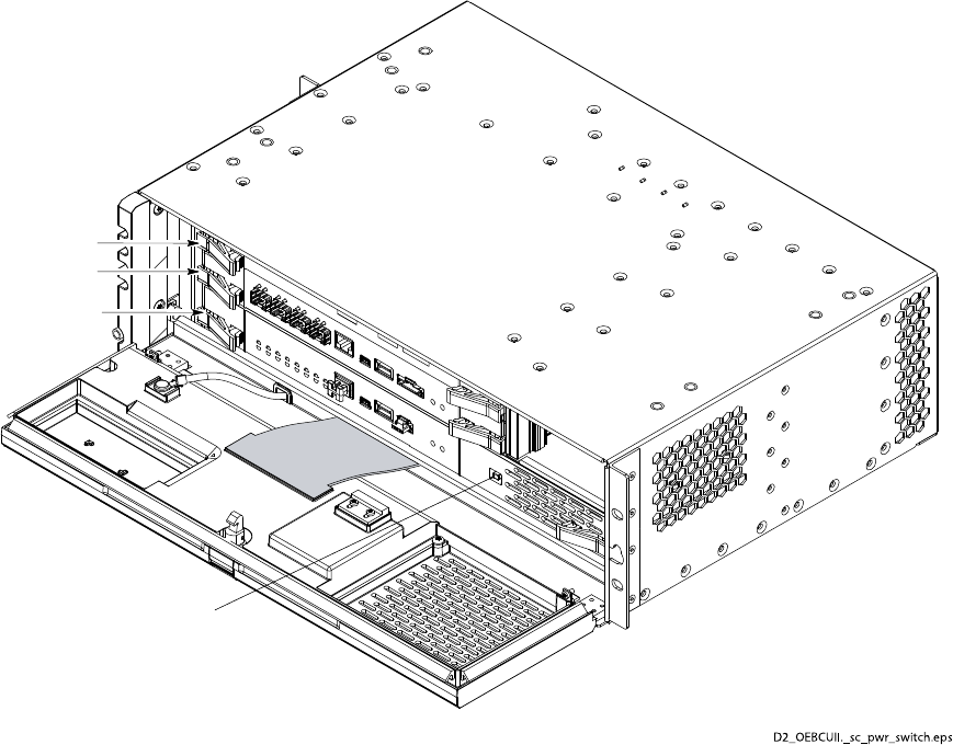
LTEeNodeBIndoorHardwareInstallationPowerUpSequence
Figure7-1BCUIIPowerSwitch
Modem 2
Modem 1
Site Controller
D2_OEBCUII._sc_pwr_switch.eps
BCUII Power Switch
68P09308A55-67-3
FEB2010
PowerUpSequenceChapter7:Power-upsequence
7-468P09308A55-6
FEB2010

Chapter
8
FieldReplaceableUnits
■■■■■■■■■■■■■■■■■■■■■■■■■■■■■■■■■■■■■■■■■■■■■■■■■■■■■■■■■■■■■
■
■
■
■
Thischapterprovidesproceduresforremovalandreplacementofcomponentsthataredeemed
FRU.
68P09308A55-68-1
FEB2010

ListofFieldReplaceableUnits(FRUs)Chapter8:FieldReplaceableUnits
ListofFieldReplaceableUnits(FRUs)
■■■■■■■■■■■■■■■■■■■■■■■■■■■■■■■■■■■■■■■■■■■■■■■■■■■■■■■■■■■■■
■
■
ThissectionliststheitemsdesignatedbyMotorolaasFieldReplaceableUnits(FRUs)forthe
eNodeB.ThefollowingtablesgivevariousinformationabouttheFRUs.
Table8-1eNodeBFRUInformation
ItemDescriptionMotorolaPartNumberNotes
BCUIIFlex4Modem(See
Notescolumn.)
STLN6724RequiresuseofModemCard
DuplexOpticalTransceivers.
ContactyourMotorola
servicerepresentativefor
moreinformation.
BCUIISiteControllerCardSTLN6725
BCUIII/OCardSTLN6704
BCUIIPowerSupplySTPN4058
Q-HSO(QuartzHigh
StabilityOscillator)
SGLA4017
BCUIIFanSGLN1946
eNodeBPDU+27VdcSTLN6905
eNodeBPDU–48VdcSTLN6906
FrameBasedRadio(FBR)STWF4000Theindoor700MHzradio.
RFSFanSTLN6904
Filter/DuplexersSTFF4046
BCUIItoFBRFiberCable
Kit
STKN4134
RemoteRadioHead(RRH)STWK4000ARemoteMountRadiofor
2600MHzbandoperation.
Includesthewallmount
bracket(STLN7037A).
RemoteRadioHead(RRH)STWF4001ARemoteMountRadiofor
700MHzUpperCband
operation.
Includesthewallmount
bracket(SYLF8377).
RemoteRadioHead(RRH)STWG4003ARemoteMountRadiofor
2100MHzbandoperation.
OpticalTransceiversfor
RRH
SYLN8961Thisbertransceivercan
beusedformulti-modeber
installationsupto100m.
OpticalTransceivers
–Modemcardand
frame-basedradio(radio
shelf)
STKN4134Partnumberisforthekit
containingabercableand
opticaltransceiversusedin
theframe-basedsystem.
8-268P09308A55-6
FEB2010

LTEeNodeBIndoorHardwareInstallationBCUIIFlex4ModemReplacement
BCUIIFlex4ModemReplacement
■■■■■■■■■■■■■■■■■■■■■■■■■■■■■■■■■■■■■■■■■■■■■■■■■■■■■■■■■■■■■
■
■
Objectives
Theprimaryobjectiveisasfollows:
•RemovethefailedFlex4ModemcardfromtheBCUIIcardcage.
•InstallareplacementFlex4ModemcardintheBCUIIcardcage.
Preparation
Requiredtools
NotoolsarerequiredtoremoveandinstalltheFlex4Modemcard.
Requireditem
Thefollowingreplacementunitisrequired:
•BCUIIFlex4ModemSTLN6724
ReplacementProcedure
PerformthefollowingproceduretoremovetheFlex4Modem.
Procedure8-1RemovalofFlex4Modem
1Performlock-outcardprocedure.
2
CAUTION
ESDhandlingprecautionsmustbeadheredtowhenhandlingthe
BCUIIplug-incards.Wearaconductive,highimpedancewriststrap.
Openthefrontpaneldoortothe90degreesposition.
3LocatethefailedModemcard.
Continued
68P09308A55-68-3
FEB2010

ReplacementProcedureChapter8:FieldReplaceableUnits
Procedure8-1RemovalofFlex4Modem(Continued)
4
NOTE
Multiplecablesmustbedisconnectedfromconnectors.If
necessary ,usemaskingtapeandamarkerandtemporarilytag
eachcableastotheproperconnectorbeforedisconnection.
Disconnecttheber-opticcablingfromthefrontofthefailedModemcard.
Forber-opticcableconnectionsperformthefollowing:
1.GrasptheLCduplexconnectoranddepressthereleasetoremovethe
bercablesfromtheberoptictransceiver .
2.Removetheberoptictransceiverfromthemodem:pulldownonthe
beroptictransceiverlatchandpullitoutoftheslot.
5Dressalldisconnectedcablesoutoftheway .
6Simultaneouslypressthelockingtabsonbothcardejectorlatches.Rotate
bothcardejectorlatchesoutfromthecardtodisengagethecardfromthe
BCUIIcage.
7GrasptheModemcardfrontpanel.PullthecardawayfromtheBCUIIcard
cage.SlidethecardoutoftheBCUIIcardcage.
PerformthefollowingproceduretoinstalltheFlex4Modem.
Procedure8-2InstallingtheFlex4Modem
1InserttheModemcardintotheBCUIIcardcageasfollows:
1.InserttheModemcardside-edgesintothecardslotrails.
2.Rotatethecardejectorlatchescompletelyoutfromthecardfrontpanel.
3.SlidethecardcompletelyintotheBCUIIcardcage.
4.Makesurethatthecardrear-edgeconnectorsfullyengagewiththe
matingbackplaneconnectors.
5.Simultaneouslypressbothcardejectorlatchesintothecardfrontpanel.
Aclickisheardandfeltwheneachejectorlatchlockingtabengagesthe
cardfrontpanelandseatsthecardintothecage.
2Reconnectallber-opticcablingtothecorrespondingconnectorsonthefront
oftheFlex4Modem.Iftheopticaltransceiverisbeingreplaced,perform
thefollowing:
•Grasptheopticaltransceiverinonehandandtheber-opticcable
connectorinthehand.Depresstheber-opticcableconnectorrelease
andpullthecableconnectoroutofthetransceiver.
Continued
8-468P09308A55-6
FEB2010

LTEeNodeBIndoorHardwareInstallationReplacementProcedure
Procedure8-2InstallingtheFlex4Modem(Continued)
•Plugtheber-opticcableconnectorintothetransceiver.Repeatthisfor
eachopticaltransceiverbeingreplaced
Grasptheopticaltransceiverwiththecableconnected,andplugtheoptical
transceiverintotheappropriatereceptacleontheFlex4Modemcard.
3TheModemcardshouldautomaticallyinitializeandbecomeactive.Notethe
followingindicationforModeminitialization:
NOTE
LEDsgosolidgreenwhenthelinksareactiveorin-service.
68P09308A55-68-5
FEB2010
BCUIISiteControllerCardReplacementChapter8:FieldReplaceableUnits
BCUIISiteControllerCardReplacement
■■■■■■■■■■■■■■■■■■■■■■■■■■■■■■■■■■■■■■■■■■■■■■■■■■■■■■■■■■■■■
■
■
Objectives
Theprimaryobjectiveisasfollows:
•RemovethefailedBCUIISiteControllercardfromtheBCUIIcardcage.
•InstallareplacementBCUIISiteControllercardintheBCUIIcardcage.
Preparation
Requiredtools
ThefollowingtoolsarerequiredtoremoveandinstallaBCUIISiteControllerCard.
•T10TORXbit
•Torquedriver
•ESD(Electro-StaticDischarge)conductive,highimpedancewriststrap
Torquerequirements
WheninstallingtheBCUIISiteControllercard,tightentheex-circuitconnectormounting
M3screwsto:
•1.1N-m(10in-lbs)
Requireditem
Thefollowingreplacementunitisrequired:
•BCUIISiteControllerCardSTLN6725
ReplacementProcedure
PerformthefollowingproceduretoremovetheBCUIISiteControllercard.
8-668P09308A55-6
FEB2010

LTEeNodeBIndoorHardwareInstallationReplacementProcedure
Procedure8-3RemovingtheBCUIISiteControllercard
1Workingatthefrontoftheframe,unlatchthefrontpaneldooroftheBCUII
andswingthedooropen.
2
CAUTION
Thefrontpaneldoormustnotbepivotedopenbeyond120degrees
fromtheclosedposition.Amechanicalstopperpinindicatesthis120
degreesposition.Topreventdamagingthedoorandtheex-circuit,
DONOTforcethedooropenbeyondthe120degreesposition.
Workingatthefrontoftheframe,opentheBCUIIfrontpaneldoorasfollows:
1.Whileholdingthedoorlatchreleasebuttondepressed,graspthetop
edgeofthefrontpaneldoor .
2.PullthedoorawayfromtheBCUIIandpivotitdownwardtoopen.
3.Openthefrontpaneldoortothe90degreesposition.
3PowerdowntheBCUII.
4ObservethatalloftheBCUIIfrontpanelLEDsareOFF .
5
CAUTION
ESDhandlingprecautionsmustbeadheredtowhenhandlingthe
BCUIIplug-incards.Wearaconductive,highimpedancewriststrap.
PlugtheendoftheESDwriststrapintotheBCUIIESDjack.Thisjackis
locatedinthefrontoftheBCUIIattherightendoftheSiteControllercard
slot.Attachthewriststraptoyourwrist.
6UsingaT10TORXbitanddriver ,completelyloosenandremovethetwo
screwsthatsecuretheex-circuitconnectortotheinsideofthefrontpanel
doorassembly .
7Grasptheex-circuitconnectoranddisconnectitfromthefrontpaneldoor
assembly .
8Openthefrontpaneldoortothe120degreesposition.Thisisthemaximum
openlimitforthedoor.Thereisamechanicalstopperpinthatindicatesthis
120degreesposition.
NOTE
ThepowercablesattachedtothefrontofthePDUinterferewith
openingtheBCUIIfrontpanelfarenoughtoreplacethecontroller .
Disconnectthesepowercablesbeforeremovingthecontroller.
9LocatethefailedSiteControllercard.
Continued
68P09308A55-68-7
FEB2010

ReplacementProcedureChapter8:FieldReplaceableUnits
Procedure8-3RemovingtheBCUIISiteControllercard(Continued)
10Simultaneouslypressthelockingtabsonbothcardejectorlatches.Rotate
bothcardejectorlatchesoutfromthecardtodisengagethecardfromthe
BCUIIcage.
11GrasptheSiteControllercardfrontpanel.Pullthecardawayfromthe
BCUIIcardcage.Slidethecardalongwiththeex-circuitoutoftheBCUII
cardcage.
PerformthefollowingproceduretoinstalltheBCUIISiteControllercard.
Procedure8-4InstallingtheBCUIISiteControllercard
1
CAUTION
Thefrontpaneldoormustnotbepivotedopenbeyond120°from
theclosedposition.Thereisamechanicalstopperpinthatindicates
this120–degreeposition.
Topreventdamagingthedoorandtheex-circuit,DONOTforce
thedooropenbeyondthe120–degreeposition.
Openthefrontpaneldoortothe120–degreeposition.Thisisthemaximum
openlimitforthedoor .
2
CAUTION
ESDhandlingprecautionsmustbeadheredtowhenhandlingthe
BCUIIplug-incards.Wearaconductive,highimpedancewriststrap.
PlugtheendoftheESDwriststrapintotheBCUIIESDjack.Thisjackis
locatedinthefrontoftheBCUIIattherightendoftheSiteControllercard
slot.Attachthewriststraptoyourwrist.
3InserttheSiteControllercardintotheBCUIIcardcageasfollows:
1.InserttheSiteControllercardside-edgesintothecardslotrails.
2.Rotatethecardejectorlatchescompletelyoutfromthecardfrontpanel.
3.Slidethecard,alongwiththeex-circuit,completelyintotheBCUII
cardcage.
4.Makesurethatthecardrear-edgeconnectorsfullyengagewiththe
matingbackplaneconnectors.
5.Simultaneouslypressbothcardejectorlatchesintothecardfrontpanel.
Youshouldfeelandhearaclickwheneachejectorlatchlockingtab
engagesthecardfrontpanelandseatsthecardintothecage.
Continued
8-868P09308A55-6
FEB2010

LTEeNodeBIndoorHardwareInstallationReplacementProcedure
Procedure8-4InstallingtheBCUIISiteControllercard(Continued)
4ConnecttheSiteControllercardex-circuitconnectortothefrontpaneldoor
assemblyasfollows:
1.Whileholdingtheopenfrontpaneldoorinthe90–degreeposition,
connecttheex-circuitconnectortothefrontpaneldoorassembly .
2.InsertthetwoM3screwsthatsecuretheex-circuitconnectortothe
frontpaneldoorassembly .
3.UsingaT10Torxbitandtorquedriver ,tightenthetwoscrewsto1.1
N-m(10in-lbs).
5PoweruptheBCUIIbymomentarilydepressingtheSiteControllercard
powerswitchsothattheswitchactuatorisintheIN/ONposition.
6
CAUTION
DONOTdresstheex-circuitdownintothedoorjamtoprevent
damagetotheex-circuit.Theex-circuitfoldsproperlywhenthe
doorisclosed.
ClosetheBCUIIfrontpaneldoor.Makesurethatthedoorlatchengages.
68P09308A55-68-9
FEB2010

eNodeFrameBasedRadioReplacementChapter8:FieldReplaceableUnits
eNodeFrameBasedRadioReplacement
■■■■■■■■■■■■■■■■■■■■■■■■■■■■■■■■■■■■■■■■■■■■■■■■■■■■■■■■■■■■■
■
■
Objectives
Theprimaryobjectiveisasfollows:
•RemovethefailedeNodeBFrameBasedRadio.
•InstallareplacementeNodeBFrameBasedRadio.
Preparation
Requiredtools
ThefollowingtoolsarerequiredtoremoveandinstallaneNodeBFrameBasedRadio
•T20TORXbit
•Torquedriver
•SMAtorquewrench
Requireditem
eNodeBFrameBasedRadio
eNodeBFrameBasedRadioReplacementProcedure
PerformthefollowingprocedurestoreplacetheeNodeBFrameBasedRadio
Procedure8-5RemovingtheeNodeBFrameBasedRadio
1
NOTE
Multiplecablesmustbedisconnectedfromconnectors.If
necessary ,usemaskingtapeandamarkerandtemporarilytag
eachcableastotheproperconnectorbeforedisconnection.
Disconnecttheber-opticcablingfromthefrontofthefailedFBR.For
ber-opticcableconnectionsperformthefollowing:
Continued
8-1068P09308A55-6
FEB2010

LTEeNodeBIndoorHardwareInstallationeNodeBFrameBasedRadioReplacementProcedure
Procedure8-5RemovingtheeNodeBFrameBasedRadio(Continued)
1.GrasptheLCduplexconnectoranddepressthereleasetoremovethe
bercablesfromtheberoptictransceiver .
2.Removetheberoptictransceiverfromtheframebasedradio:pull
downontheberoptictransceiverlatchandpullitoutoftheslot.
2RemovethetwoRFconnectionsatthefrontoftheFBRusingSMAwrench.
3UsingaT20TORXbitanddriver ,completelyloosenthetwoscrewsthat
securetheFBR.
4SlideFBRoutoftheRadio/FilterShelf.
Procedure8-6InstallingtheeNodeBFrameBasedRadio
1InsertFBRintotheRadio/FilterShelf.
2UsingaT20TORXbitanddriver,tightenthetwoscrewsthatsecurethe
FBRto2.2N-m(20in-lbs).
3ReconnectthetwoRFconnectionsatthefrontoftheFBRusingSMAtorque
wrench.
4InstallberoptictransceiversintotheFBRandreconnecttheberoptic
cables.
5Performrecommissioningtaskstoplacetheunitbackinservice.
68P09308A55-68-11
FEB2010
Filter/DuplexerReplacementChapter8:FieldReplaceableUnits
Filter/DuplexerReplacement
■■■■■■■■■■■■■■■■■■■■■■■■■■■■■■■■■■■■■■■■■■■■■■■■■■■■■■■■■■■■■
■
■
Objectives
Theprimaryobjectiveisasfollows:
•RemoveFilter/Duplexer
•InstallFilter/Duplexer
Preparation
Requiredtools
ThefollowingtoolsarerequiredtoremoveandinstallaFilter/Duplexer.
•T20TORXbit
•Torquedriver
•10mmhexsocket
•SMAtorquewrench
•N-connectortorquewrench
Torquerequirements
•M4screwsto2.2N-m(20in-lb)
•M6nutsto5.1N-m(45in-lb)
Requireditem
700MHzUpperCbandFilter/DuplexerSTFF4046
Filter/DuplexerReplacementProcedure
PerformthefollowingprocedurestoreplacetheFilter/Duplexer.
8-1268P09308A55-6
FEB2010

LTEeNodeBIndoorHardwareInstallationFilter/DuplexerReplacementProcedure
Procedure8-7RemovingtheFilter/Duplexer
1RemoveRadio/FilterShelf.
2Removethe2RFcables(RxAandRxB)attherearoftheDuplexer.
3Usinga10mmsocketand3-inchsocketextension,removethetwoM6nuts
atthebottomoftheRadio/Filtershelf.
4UsingaT20Torx,removethetwoM4screwsatthefrontfaceofthe
Radio/FilterShelfDuplexerbody .
5RemovetheFilter/DuplexerunitfromtheRadio/FilterShelf.
Procedure8-8InstallingFilter/Duplexer
1InserttheFilter/DuplexerintotheRadio/FilterShelfavoidingthe2RFcables.
2PulltheFilter/DuplexertowardsthefrontsotheFilter/Duplexerbodyrests
againsttheinsidefrontfaceoftheRadio/FilterShelfchassis.
3UsingaT20Torx,screwtwoM4screwsthroughthefrontfaceofthe
Radio/FilterShelfintotheDuplexerbody .Torqueto1.8N-m(16in-lb).
4Usinga10mmsocketand3-inchsocketextension,securetheFilter/Duplexer
tothetwoM6studsatthebottomoftheRadio/FilterShelfwithtwoM6nuts.
Torqueto5.1N-m(45in-lb).
5Matethe2RFcablesattherearoftheFilter/Duplexer.Ensurethatthecable
bendsarenolessthan6mm(1/4inch)diameter .
68P09308A55-68-13
FEB2010
Radio/FilterShelfFanTrayReplacementChapter8:FieldReplaceableUnits
Radio/FilterShelfFanTrayReplacement
■■■■■■■■■■■■■■■■■■■■■■■■■■■■■■■■■■■■■■■■■■■■■■■■■■■■■■■■■■■■■
■
■
Objective
Theobjectiveisasfollows:
•RemoveRadio/FilterShelfFanTray
•InstallRadio/FilterShelfFanTray
Preparation
Requiredtools
ThefollowingtoolsarerequiredtoremoveandinstalltheRadio/FilterShelfFanTray .
•T25TORXbit
•Driver
Requireditem
Thefollowingreplacementunitisrequired:
•RFSFanTrayMotorolamodelSTLN6904
Radio/FilterShelfFanTrayreplacementprocedure
PerformthefollowingprocedurestoreplacetheRFSFanTray
8-1468P09308A55-6
FEB2010
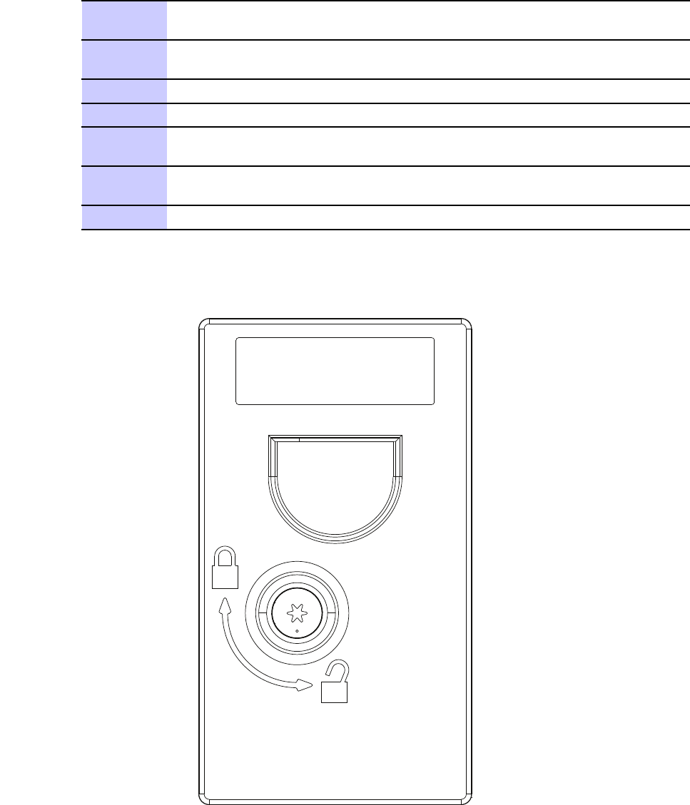
LTEeNodeBIndoorHardwareInstallationRadio/FilterShelfFanTrayreplacementprocedure
Procedure8-9ReplacingtheRFSFantray
1InserttheT25TORXbitintotherecessinthelockingcamonthefrontof
thefantray .
2Usingdriver ,rotatecam90degreescounterclockwise(orientationdotaligns
withtheunlockedlockfeatureonthefrontofthefantray .SeeFigure8-1).
3Slidethefantrayassemblyoutofthefrontoftheradioshelf.
4Slidethenewfantrayassemblyintotheradioshelf.
5InserttheT25TORXbitintotherecessinthelockingcamonthefrontof
thefantray .
6Usingadriver,rotatecam90degreesclockwise(orientationdotalignswith
thelockedlockfeatureonthefrontofthefantray .SeeFigure8-2).
7Restorepowertotheradioshelf(ifneeded,fantrayishot-pluggable).
Figure8-1RFSfantrayinunlockedposition
68P09308A55-68-15
FEB2010
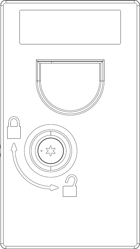
Radio/FilterShelfFanTrayreplacementprocedureChapter8:FieldReplaceableUnits
Figure8-2RFSfantrayinlockedposition
8-1668P09308A55-6
FEB2010
LTEeNodeBIndoorHardwareInstallationQ-HSO(QuartzHighStabilityOscillator)Replacement
Q-HSO(QuartzHighStabilityOscillator)Replacement
■■■■■■■■■■■■■■■■■■■■■■■■■■■■■■■■■■■■■■■■■■■■■■■■■■■■■■■■■■■■■
■
■
Q-HSO(QuartzHighStabilityOscillator)Replacement
Objective
Theobjectiveisasfollows:
•RemovetheBCUIIcardcageassemblyfromtheframe
•ReplacetheQ-HSOlocatedontherearpaneloftheBCUIIcardcageassembly
•ReinstalltheBCUIIcardcageassemblyintheframe
Introduction
TheoptionalQ-HSOislocatedontheBCUIIrearpanel(seeFigure8-3).Itismountedinthe
middleoftherearpanelbetweenthefantrayandthePSU.
TheQ-HSOisabackupsynchronizationsourceformaintainingBTSsystemtiming
established/sourcedbyeithertheoptionalRFGPSreceivermodulelocatedinthefrontpanel
doorassembly .
TheQ-HSOcontainsahighstabilityquartzcrystaloscillator .
TheQ-HSOhasa9–pinD-connectorthatconnectstotheMSOconnectorontheBCUIIrear
panel.ThisconnectionallowstheBCUIItosupplyDCpowertotheQ-HSO.Inaddition,
control/datasignalsareexchangedbetweentheBCUIISiteControllercardandtheQ-HSO
throughthisconnection.
TheQ-HSOprovidesa1PulsePerSecond(1PPS)timingsignal.This1PPSsignalisapplied
totheSiteControllercard.
IfGPSsatellitetrackingislostoriftheRFGPSreceivermodulefails,theQ-HSOmaintainsBTS
systemtimingforupto24hours.
Preparation
Requiredtools
ThefollowingtoolsarerequiredtoremoveandinstallaQ-HSO:
•T20TORXbit
•Torquedriver
68P09308A55-68-17
FEB2010

TorquerequirementsChapter8:FieldReplaceableUnits
Torquerequirements
WheninstallingtheQ-HSO,tightentheQ-HSOM4thumbscrewto:
•2.3N-m(20in-lbs)
Requireditem
Thefollowingreplacementunitisrequired:
•Q-HSO,MotorolamodelSGLA4017
Q-HSOreplacementprocedure
PerformthestepsdescribedinProcedure8-10toreplacetheQ-HSO.
Procedure8-10ReplacingtheQ-HSO
1RemovetheBCUIIcardcageassemblyfromtheframe.
2LocatetheQ-HSOontheBCUIIrearpanel.
3UsingaT20TORXbitanddriver ,loosenthethumbscrewontheQ-HSO(seeFigure8-3).
Usingyourthumbandnger ,completelyloosenthecaptivethumbscrew .
4Graspthetopend(thatis,thethumbscrewend)ofQ-HSOandpullitawayfromtheBCUII
rearpaneluntilthe9–pinD-connectorsarefullydisengaged.
5SlidetheQ-HSOuntilthetabonthebottomendoftheQ-HSOisdisengagedfromthe
retainingslotontheBCUIIrearpanel.
6WiththereplacementQ-HSOproperlypositioned,insertthetabonthebottomendofthe
Q-HSOundertheretainingslotontheBCUIIrearpanel.
7AligntheQ-HSO9–pinD-connectorwiththeMSOconnectorontheBCUIIrearpanel.
FirmlypushthetopendoftheQ-HSOagainsttheBCUIIrearpaneluntiltheconnectorsare
fullyengaged.
8AligntheQ-HSOthumbscrewwiththethreadedhole.UsingaT20TORXbitanddriver,
tightenthethumbscrewto2.3N-m(20in-lbs).
9ReinstalltheBCUIIcardcageassemblyintotheframeaccordingthestepsinProcedure8-12
Reinstallingcardcageassemblyonpage8-23.
Referencediagram
ThefollowingdiagramhelpsclarifyandsupportcertainstepsofProcedure8-10.
8-1868P09308A55-6
FEB2010
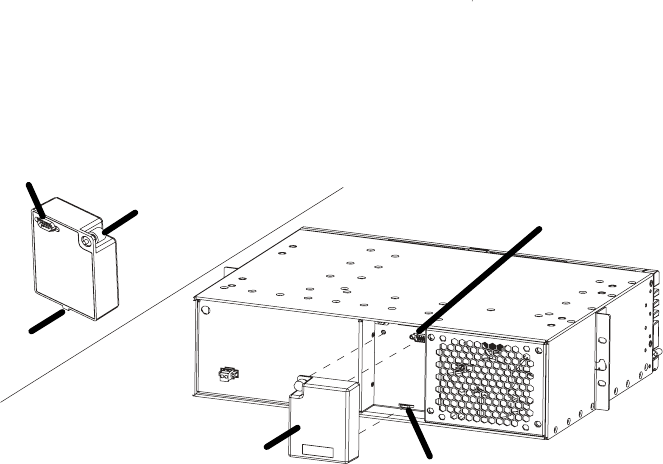
LTEeNodeBIndoorHardwareInstallationReferencediagram
Figure8-3Q-HSOremovalandinstallation
ti-cdma-05694.eps
ti-cdma-05694.eps
Mounting Tab Slot
Q-HSO
Q-HSO
Rear View
9-Pin Sub-D Connector
9-Pin Sub-D Connector
Captive Thumbscrew
Mounting Tab
68P09308A55-68-19
FEB2010
BCUIIcardcageassemblyreplacementproceduresChapter8:FieldReplaceableUnits
BCUIIcardcageassemblyreplacementprocedures
■■■■■■■■■■■■■■■■■■■■■■■■■■■■■■■■■■■■■■■■■■■■■■■■■■■■■■■■■■■■■
■
■
PerformthefollowingproceduretoremovetheBCUIIcardcageassemblyfromtheframe.
Objectives
Theprimaryobjectiveisasfollows:
•RemovethefailingBCUIIcardcageassemblyfromtheframe
•ReplaceaFRUontherearpaneloftheBCUIIcardcageassembly
•ReinstalltheBCUIIcardcageassemblyintheframe
Introduction
TheBCUIIcardcageassemblyprovidesarackmountablefacilityforhousingalloftheBCUII
electronics.ItalsoprovidesinterconnectionoftheBCUIIelectronicsaswellasconnectionto
theexternalcustomerandsiteequipment.
TheBCUIIcardcageassemblyincludes:backplane,frontpaneldoorassembly ,andfantray;all
installed.
Preparation
Requiredtools
ThefollowingtoolsarerequiredtoremoveandinstallaBCUIIcardcageassembly .
•T20TORXbit
•T30TORXbit
•T10TORXbit
•10mmsocket
•3/8inchratchet
•Flat-bladescrewdriver
•Torquedriver
•ESD(Electro-StaticDischarge)conductive,highimpedancewriststrap
8-2068P09308A55-6
FEB2010

LTEeNodeBIndoorHardwareInstallationPreparation
Torquerequirements
Wheninstallingthebuilt-upBCUIIcardcage,tightenthecorrespondingfastenersasfollows:
•BCUIIgroundwirelugM6nuts–4.5N-m(39.8in-lb)
•FibercoverM4screws–2.3N-m(20in-lbs)
Requireditem
Thefollowingreplacementunitisrequired:
•BCUIIcardcageassembly ,MotorolapartnumberSGLN1945
ReplacementProcedure
PerformthestepsinProcedure8-11andProcedure8-12toreplacetheBCUIIcardcage.
Procedure8-11RemovingtheBCUIIcardcage
1
CAUTION
Thefrontpaneldoormustnotbepivotedopenbeyond120degrees
fromtheclosedposition.Thereisamechanicalstopperpinthat
indicatesthis120degreesposition.
Topreventdamagingthedoorandtheex-circuit,DONOTforce
thedooropenbeyondthe120degreesposition.
Workingatthefrontoftheframe,opentheBCUIIfrontpaneldoorasfollows:
1.Whileholdingthedoorlatchreleasebuttondepressed,graspthetop
edgeofthefrontpaneldoor .
2.PullthedoorawayfromtheBCUIIandpivotitdownwardtoopen.
3.Openthefrontpaneldoortothe90degreesposition.
2OntherightendoftheSiteControllercardfrontpanel,locatethepower
ON/OFFswitch.
3PowerdowntheBCUIIbymomentarilydepressingthepowerswitchsothat
theswitchactuatorisintheOUT/OFFposition.
4ObservethatalloftheBCUIIfrontpanelLEDsareOFF .
5SettheexternalBCUIIpowersourcetoOFF .
6Disconnectallofthecablesconnectedtoconnectorsontheoutsideofthe
BCUIIfrontpaneldoor.DressthesecablesawayfromthefrontoftheBCUII.
Continued
68P09308A55-68-21
FEB2010

PreparationChapter8:FieldReplaceableUnits
Procedure8-11RemovingtheBCUIIcardcage(Continued)
7RemovethebercoverattachedtotheBCUIIcardcagefrontleftcorner .
Thetwoscrewssecuringthebercoverarelocatedjustinsidetheopen
frontpaneldoor(seeFigure8-4).UsingaT20TORXbitanddriver,loosen
andremovethetwoscrews.Graspthebercoverandpullitawayandout
fromtheBCUIIcardcage.
8Locatethegroundwire,withthedoubleholelug,attachedtotheBCUIIcard
cagefrontleftcornerjustinsidetheopenfrontpaneldoor(see).Disconnect
thegroundwirelugbyusinga10mmsocketandratchettoloosenandremove
thetwoM6nutsthatsecurethegroundwirelugtothethreadedstuds.
9
NOTE
Multiplecablesarebeingdisconnectedfromtheconnectors.If
necessary ,usemaskingtapeandamarkerandtemporarilytag
eachcableastotheproperconnectorbeforedisconnection.
Disconnecttheber-opticcablingandanyothercablingfromthefrontofthe
Modemcards.Forber-opticcableconnectionsperformthefollowing:
1.GrasptheopticaltransceiverbytheconnectorattheModemcard.
2.Depresstheopticaltransceiverconnectorreleaseandpullthe
transceiver,alongwiththecable,outoftheModemcardreceptacle.
10Pulloutthelooseendsofber-opticcablesthroughthegrommetopenings.
Movetheber-opticcablesandthedisconnectedgroundwirewithlugoutof
thefrontoftheBCUII.
DressthesecablesawayfromthefrontoftheBCUII.
11RemovetheBCUIIrackmountingscrewsasfollows:
1.Usingtheappropriatedriver ,loosenandremoveallbutoneofthe
screwsineachsidemountbracket.
2.WhilesupportingtheBCUIIcardcage,removetheremainingscrewin
eachsidemountbracket.
12GrasptheBCUIIcardcageandpullitpartiallyoutoftheframetoaccess
therearpanel.
13DisconnectallofthecablesconnectedtoconnectorsontherearoftheBCUII.
Thesecablesinclude:
•Cableconnectedtotheinputpowerconnectorlocatedonthelowerleft
cornerofthePSU.
14CompletelypulltheBCUIIcardcageoutoftheframeandmoveittoawork
surface.
8-2268P09308A55-6
FEB2010
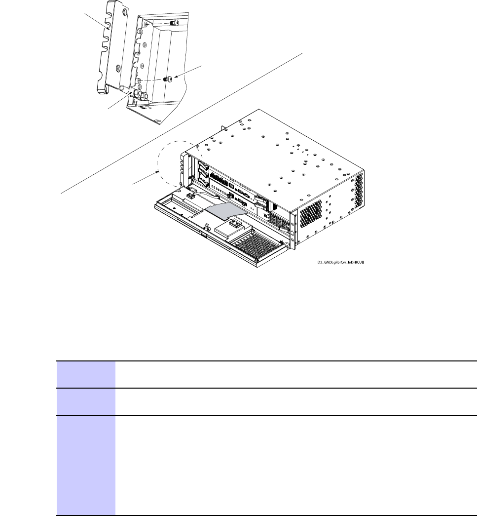
LTEeNodeBIndoorHardwareInstallationPreparation
Figure8-4BCUIIFiberCover
ti-cdma-05694.eps
Fiber Cover
Ground Lug
2X Screws
See Detail A
Detail A
D2_GNDLgFbrCvr_InDrBCUII
Reinstallcardcageassembly
Procedure8-12Reinstallingcardcageassembly
1Positionthebuilt-upreplacementBCUIIcardcageassemblyinfrontofthe
frame.
2PartiallyinserttheBCUIIcardcageintotheframe,sotherearpanelcan
stillbeaccessed.
3Reconnectthecorrespondingcablestotheconnectorsontherearofthe
BCUII.Thesecablesinclude:
1.Cableconnectiontothe–48Vdcinputpowerconnectorlocatedonthe
lowerleftcornerofthe–48VdcPSU(asviewedfromtherearofthe
BCUII).
2.Usingaat-bladescrewdriver ,tightenthetworetainingscrewsonthe
powerconnector.
Continued
68P09308A55-68-23
FEB2010

PreparationChapter8:FieldReplaceableUnits
Procedure8-12Reinstallingcardcageassembly(Continued)
4CompletelyinserttheBCUIIcardcageintotheframe.Aligntheholesineach
sidemountingbracketwiththeapplicableholesintheframerails.
WhilesupportingtheBCUIIcardcage,insertscrewsintothetopandbottom
holesineachsidemountingbracket.
Usingtheappropriatedriver ,tightenthescrewstothepropertorque
specication.
5Openthefrontpaneldoortothe90degreesposition.
6Routethedisconnectedgroundwirewiththedoubleholelugthroughthe
appropriatecablegroove,locatedattheBCUIIcardcagefrontleftcorner,
andintotheinsideofthedoorpanelarea(seeFigure8-4).
NOTE
IfthereplacementBCUIIcardcagealreadyhasaluginstalled,
removeitbeforeproceedingtostep7.
7Attachthegroundwiredoubleholelugtothethreadedstudslocatedatthe
BCUIIcardcagefrontleftcorner.
SecurethegroundwirelugtothethreadedstudswiththetwoM6nuts.Using
a10mmsocketandtorquedriver,tightenthenutsto4.5N-m(39.8in-lb).
8Routethedisconnectedber-opticcablesthroughtheappropriateopenings
inthegrommetlocatedattheBCUIIcardcagefrontleftcorner,andintothe
insideofthedoorpanelarea.
9Reconnectallber-opticcablingtothecorrespondingconnectorsonthefront
oftheModemcards.
Grasptheopticaltransceiver,withthecableconnected,andplugtheoptical
transceiverintotheappropriatereceptacleontheModemcard.
Repeatthisstepforeachber-opticcable.
10AttachthebercovertotheBCUIIcardcagefrontleftcorner(seeFigure8-4).
SecurethebercoverwiththetwoM4screws.UsingaT20TORXbitand
torquedriver,tightenthescrewsto2.3N-m(20in-lbs).
11Reconnectallofthecablestothecorrespondingconnectorsontheoutsideof
theBCUIIfrontpaneldoor .
12SettheexternalBCUIIpowersourcetoON.
13PoweruptheBCUIIbymomentarilydepressingtheSiteControllercard
powerswitchsothattheswitchactuatorisintheIN/ONposition.
14
CAUTION
DONOTdresstheex-circuitdownintothedoorjamtoprevent
damagetotheex-circuit.Theex-circuitfoldsproperlywhenthe
doorisclosed.
ClosetheBCUIIfrontpaneldoor.Makesurethatthedoorlatchengages.
8-2468P09308A55-6
FEB2010
LTEeNodeBIndoorHardwareInstallationBCUIIFanTrayReplacement
BCUIIFanTrayReplacement
■■■■■■■■■■■■■■■■■■■■■■■■■■■■■■■■■■■■■■■■■■■■■■■■■■■■■■■■■■■■■
■
■
Objectives
Theprimaryobjectiveisasfollows:
•RemovetheBCUIIcardcageassemblyfromtheframe
•ReplacethefantraylocatedontherearpaneloftheBCUIIcardcageassembly
•ReinstalltheBCUIIcardcageassemblyintheframe
Introduction
ThefantrayismountedintherightsideoftheBCUIIrearpanelasviewedfromtherearofthe
BCUII(seeFigure8-5).Thefantraycontainsasinglefan.Thefandrawscoolairinfromtheair
intakelocatedalongthefrontoftheBCUII.ThecoolairpassesthroughtheentireBCUIIand
over/underalloftheBCUIIinternalcircuitry .Thefanexhauststhecoolingairouttherearofthe
BCUII.TheelectricalconnectionsforbothDCoperatingpowerandthefancontrol/monitoring
signalsaremadethroughacablethatispartofthefantray .Thefantraycableconnectorplugs
intotheBCUIIbackplane.Thisconnectionismademanuallyandisaccessiblethroughthefront
oftheBCUIIafterremovingtheSiteControllerandModem1cards.
Preparation
Requiredtools
ThefollowingtoolsarerequiredtoremoveandinstallaBCUIIfantray .
•T20TORXbit
•Torquedriver
•ESD(Electro-StaticDischarge)conductive,highimpedancewriststrap
Torquerequirements
WheninstallingtheBCUIIfantray ,tightenthecaptiveM4mountingscrewsto:
•2.3N-m(20in-lbs)
68P09308A55-68-25
FEB2010

ReplacementProcedureChapter8:FieldReplaceableUnits
Requireditem
Thefollowingreplacementunitisrequired:
•Fantray ,MotorolamodelSGLN1946
ReplacementProcedure
PerformthestepsdescribedinProcedure8-13toremovetheBCUIIfantray .
Procedure8-13RemovingtheBCUIIfantray
1RemovetheBCUIIcardcageassemblyfromtheframeaccordingthestepsin
ReplacementProcedureonpage8-3
2WorkingatthefrontoftheBCUIIcardcage,unlatchthefrontpaneldoorof
theBCUIIandswingthedooropen.
3
CAUTION
Thefrontpaneldoormustnotbepivotedopenbeyond120degrees
fromtheclosedposition.Thereisamechanicalstopperpinthat
indicatesthis120degreesposition.
Topreventdamagingthedoorandtheex-circuit,DONOTforce
thedooropenbeyondthe120degreesposition.
Workingatthefrontoftheframe,opentheBCUIIfrontpaneldoorasfollows:
1.Whileholdingthedoorlatchreleasebuttondepressed,graspthetop
edgeofthefrontpaneldoor .
2.PullthedoorawayfromtheBCUIIandpivotitdownwardtotheopen.
3.Openthefrontpaneldoortothe90degreesposition.
4
CAUTION
ESDhandlingprecautionsmustbeadheredtowhenhandlingthe
BCUIIplug-incards.Wearaconductive,highimpedancewriststrap.
PlugtheendoftheESDwriststrapintotheBCUIIESDjack.Thisjackis
locatedinthefrontoftheBCUIIattherightendoftheSiteControllercard
slot.Attachthewriststraptoyourwrist.
Continued
8-2668P09308A55-6
FEB2010

LTEeNodeBIndoorHardwareInstallationReplacementProcedure
Procedure8-13RemovingtheBCUIIfantray(Continued)
5RemovetheSiteControllercardasfollows:
1.LocatetheSiteControllercard.
2.Holdtheopenfrontpaneldoorinthe90degreesposition.
3.UsingaT10TORXbitanddriver,completelyloosenandremovethetwo
screwsthatsecuretheex-circuitconnectortotheinsideofthefront
paneldoorassembly .
4.Grasptheex-circuitconnectoranddisconnectitfromthefrontpanel
doorassembly .
5.Openthefrontpaneldoortothe120degreesposition.Thisisthe
maximumopenlimitforthedoor.Thereisamechanicalstopperpinthat
indicatesthis120degreesposition.
6.Simultaneouslypressthelockingtabsonbothcardejectorlatches.
Rotatebothcardejectorlatchesoutfromthecardtodisengagethe
cardfromtheBCUIIcage.
7.GrasptheSiteControllercardfrontpanel.Pullthecardawayfrom
theBCUIIcardcage.Slidethecard,alongwiththeex-circuit,outof
theBCUIIcardcage.
6RemovetheModem1cardbyperformingthestepsinProcedure8-1Removal
ofFlex4Modem
7ReachinthroughthevacantSiteControllercardandModem1cardslots
towardthefantrayandtheleftendoftheBCUIIcagebackplane.Locatethe
fantraycableconnectorthatispluggedintotheBCUIIbackplane.
8Disconnectthefantraycableconnectorbygraspingtheconnectorandpulling
itawayfromthebackplane.
9LocatethefantrayontheBCUIIrearpanel.
10UsingaT20TORXbitanddriver ,completelyloosenthefourcaptivescrews
thatsecurethefantraytotherearoftheBCUII(seeFigure8-5).Thereis
captivescrewlocatedineachcornerofthefantray .
11
NOTE
Itmaybenecessarytoreachinthroughthevacantcardslotsand
pushthefantrayouttherearoftheBCUII.
GraspthefantrayandpullitoutfromtherearoftheBCUII.
PerformthestepsdescribedinProcedure8-14toinstallthefantray .
68P09308A55-68-27
FEB2010

ReplacementProcedureChapter8:FieldReplaceableUnits
Procedure8-14InstallingtheBCUIIfantray
1Withthereplacementfantrayproperlypositioned,insertthefantrayandcableintothe
openingontherearoftheBCUII(SeeFigure8-5).Besurethatthefantraycabledoes
notgetpinched.
2AtthefrontoftheBCUII,reachinthroughthevacantSiteControllercardandModem1
cardslotstowardthefantrayandtheleftendoftheBCUIIcagebackplane.
LocatethefantraycableconnectorandplugitintotheBCUIIbackplane.
3SecurethefantraytotherearoftheBCUIIasfollows(SeeFigure8-5):
1.UsingaT20Torxbitanddriver,handtightenthefourcaptivescrews.
2.Useanalternatingdiagonalscrewtightenpattern.
3.Afterhandtightening,useaT20Torxbitandtorquedrivertotightenthefourcaptive
screwsto2.3N-m(20in-lbs).
4WorkingatthefrontoftheBCUIIcardcage,reinstalltheModem1cardbyperforming
thestepsinProcedure8-2.
5ReinstalltheSiteControllerintotheBCUIIcardcageasfollows:
1.InserttheSiteControllercardside-edgesintothecardslotrails.
2.Rotatethecardejectorlatchescompletelyoutfromthecardfrontpanel.
3.Slidethecard,alongwiththeex-circuit,completelyintotheBCUIIcardcage.
4.Makesurethatthecardrear-edgeconnectorsfullyengagewiththematingbackplane
connectors.
5.Simultaneouslypressbothcardejectorlatchesintothecardfrontpanel.Feelandhear
aclickwheneachejectorlatchlockingtabengagesthecardfrontpanelandseats
thecardintothecage.
6ConnecttheSiteControllercardex-circuitconnectortothefrontpaneldoorassembly
asfollows:
1.Whileholdingtheopenfrontpaneldoorinthe90–degreeposition,connectthe
ex-circuitconnectortothefrontpaneldoorassembly .
2.InsertthetwoM3screwsthatsecuretheex-circuitconnectortothefrontpanel
doorassembly .
3.UsingaT10Torxbitandtorquedriver,tightenthetwoscrewsto1.1N-m(10in-lbs).
7ReinstalltheBCUIIcardcageassemblyintotheframebyperformingthestepsin
Procedure8-12Reinstallingcardcageassemblyonpage8-23.
8-2868P09308A55-6
FEB2010
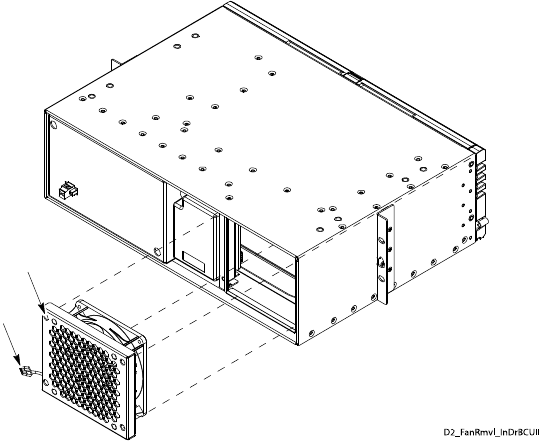
LTEeNodeBIndoorHardwareInstallationReplacementProcedure
Figure8-5Fantrayremovalandinstallation
ti-cdma-05694.eps
4X Recessed Access Holes for Captive Screws
D2_Fan Rmvl_InDrBCUII
Fan Tray Power/Control Connector
68P09308A55-68-29
FEB2010

eNodeBPDUReplacementChapter8:FieldReplaceableUnits
eNodeBPDUReplacement
■■■■■■■■■■■■■■■■■■■■■■■■■■■■■■■■■■■■■■■■■■■■■■■■■■■■■■■■■■■■■
■
■
Objective
Theobjectiveisasfollows:
•RemoveeNodeBPDU
•InstallreplacementeNodeBPDU
Preparation
Requiredtools
ThefollowingtoolsarerequiredtoremoveandinstalltheeNodeBPDU.
•TorqueWrenches
SMATorqueWrench
Torquedrivercapableofdrivingbitsat.
Torquedrivercapableoftorquing10mmsocketto5.1N-m(45in-lb).
•BitDriverandBits
TORXDriver
T20TORXbit
T25TORXbit
T30TORXbit
Torquedriver
10mmsocket
FlatBladeScrewdriverBit
•Zipties
•ESD(Electro-StaticDischarge)conductive,highimpedancewriststrap
8-3068P09308A55-6
FEB2010

LTEeNodeBIndoorHardwareInstallationeNodeBPDUreplacementprocedure
Torquerequirements
•1.1N-m(10in-lb),1.3N-m(12in-lb)
•M4screws1.8N-m(16in-lb)
•M5screws4.7N-m(42in-lb)
•M6x16screws5.1N-m(45in-lb)
Requireditem
Thefollowingreplacementunitisrequired:
•eNodeBPDU+27Vdc,MotorolamodelSTLN6905
•eNodeBPDU–48Vdc,MotorolamodelSTLN6906
eNodeBPDUreplacementprocedure
Procedure8-15ReplacingtheeNodeBPDU
1Removesourcepower.
2Disconnectthesourcepowercableandthegroundcable(ifequipped)atthe
sourceifrequiredforadequateserviceloop.
3Unplugallpowercables.
4UsingaDVM,conrmthatthereisnovoltageonthePDU.
5UsingaT25Torxdriver,loosenandremovethefourrackmountingscrews
thatsecurethePDUtotherack.RemovethePDUfromtherack.
6UsingaT30Torxdriver,removethepowerlugsfromthePDUthroughthe
accesspanel.
Procedure8-16InstallingPDUtoRack
1MountthePDUinthe19-inchrack.
NOTE
MountthePDUinthesamerackunitasthePDUthatwasremoved
inProcedure8-15.
IfotherequipmentaremountedabovethePDU,thesourcepower
cablemustbeconnectedbeforeinstallingthePDU.
Continued
68P09308A55-68-31
FEB2010
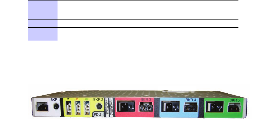
eNodeBPDUreplacementprocedureChapter8:FieldReplaceableUnits
Procedure8-16InstallingPDUtoRack(Continued)
2Usingthesamefourrackmountingscrews,installtwoscrewspersideusing
aT25Torxbitandtorqueto4.7N-m(42in-lb).
3PerformthestepsinProcedure3-5toreconnectpowertothePDU.
4Ifusinganon-Motorolarack,performthestepsinProcedure3-4toground
thePDU.
Figure8-6PDU
PDU front.eps
8-3268P09308A55-6
FEB2010