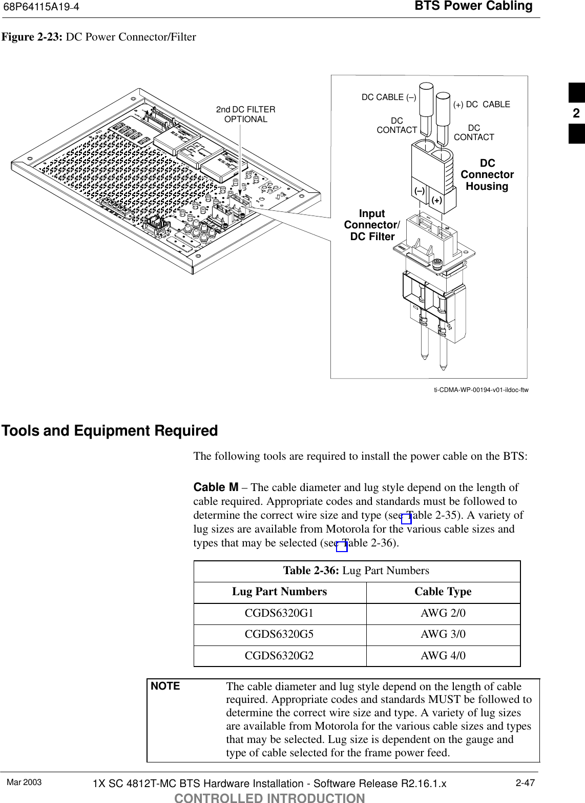
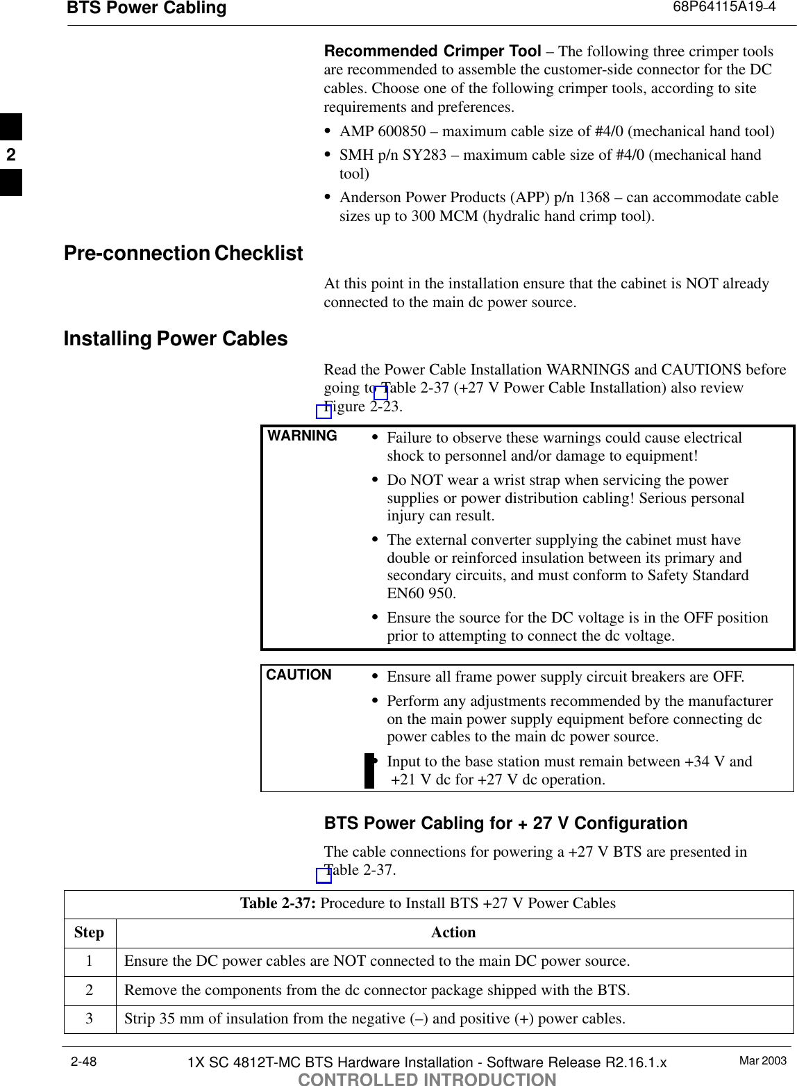
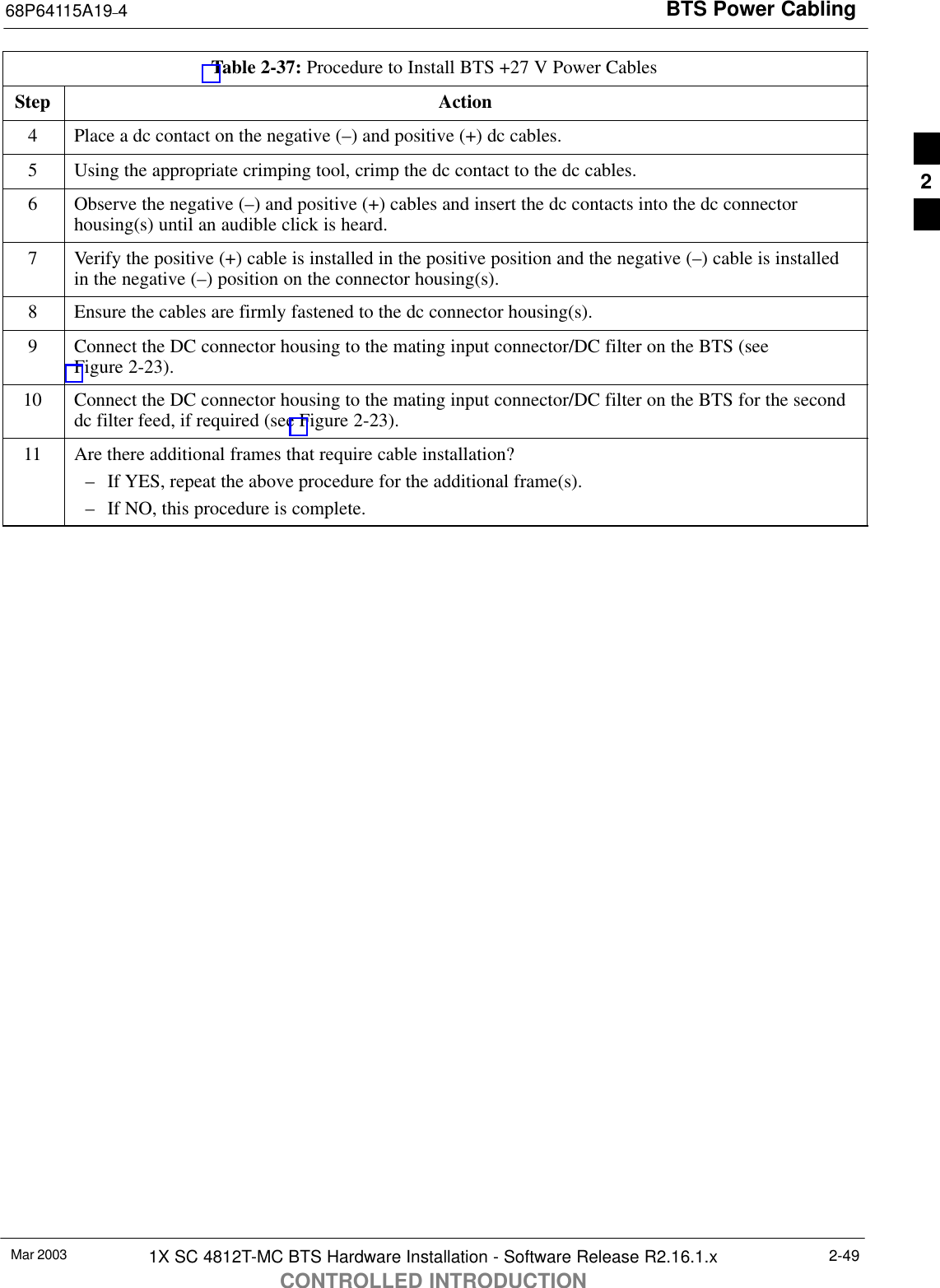
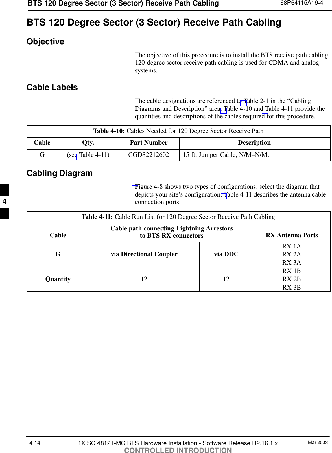
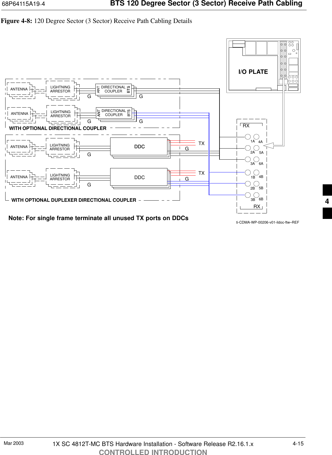
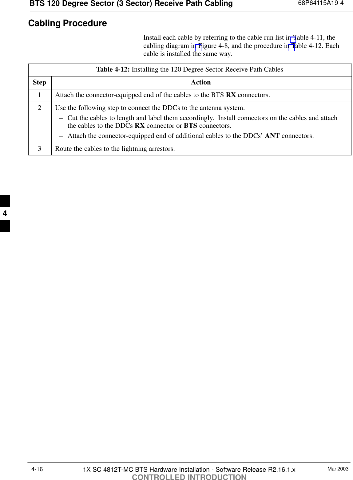
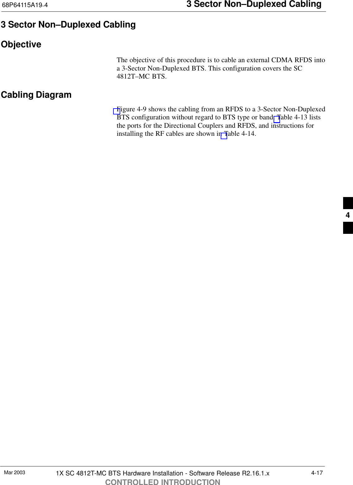
Nokia Solutions and Networks T5DX1 SC4812T-MC 1X/1X-DO @ 800 MHz CDMA BTS User Manual 115a19 4

Nokia Solutions and Networks SC4812T-MC 1X/1X-DO @ 800 MHz CDMA BTS 115a19 4

Users Manual

CONTROLLED INTRODUCTION68P64115A19–4Mar 2003ENGLISHCDMASoftware Release R2.16.1.xTechnicalInformation1X SC 4812T-MC BTS HardwareInstallation800 MHz
CONTROLLEDINTRODUCTIONSPECIFICATIONS SUBJECT TO CHANGE WITHOUT NOTICENoticeWhile reasonable efforts have been made to assure the accuracy of this document, Motorola, Inc. assumes no liability resulting from anyinaccuracies or omissions in this document, or from use of the information obtained herein. The information in this document has beencarefully checked and is believed to be entirely reliable. However, no responsibility is assumed for inaccuracies or omissions. Motorola,Inc. reserves the right to make changes to any products described herein and reserves the right to revise this document and to makechanges from time to time in content hereof with no obligation to notify any person of revisions or changes. Motorola, Inc. does notassume any liability arising out of the application or use of any product, software, or circuit described herein; neither does it conveylicense under its patent rights or the rights of others.It is possible that this publication may contain references to, or information about Motorola products (machines and programs),programming, or services that are not announced in your country. Such references or information must not be construed to meanthat Motorola intends to announce such Motorola products, programming, or services in your country.CopyrightsThis instruction manual, and the Motorola products described in this instruction manual may be, include or describe copyrightedMotorola material, such as computer programs stored in semiconductor memories or other media. Laws in the United States andother countries preserve for Motorola certain exclusive rights for copyrighted material, including the exclusive right to copy,reproduce in any form, distribute and make derivative works of the copyrighted material. Accordingly, any copyrighted Motorolamaterial contained herein or in the Motorola products described in this instruction manual may not be copied, reproduced,distributed, merged or modified in any manner without the express written permission of Motorola. Furthermore, the purchase ofMotorola products shall not be deemed to grant either directly or by implication, estoppel, or otherwise, any license under thecopyrights, patents or patent applications of Motorola, as arises by operation of law in the sale of a product.Usage and Disclosure RestrictionsLicense AgreementThe software described in this document is the property of Motorola, Inc. It is furnished by express license agreement only and maybe used only in accordance with the terms of such an agreement.Copyrighted MaterialsSoftware and documentation are copyrighted materials. Making unauthorized copies is prohibited by law. No part of the software ordocumentation may be reproduced, transmitted, transcribed, stored in a retrieval system, or translated into any language orcomputer language, in any form or by any means, without prior written permission of Motorola, Inc.High Risk ActivitiesComponents, units, or third–party products used in the product described herein are NOT fault–tolerant and are NOT designed,manufactured, or intended for use as on–line control equipment in the following hazardous environments requiring fail–safecontrols: the operation of Nuclear Facilities, Aircraft Navigation or Aircraft Communication Systems, Air Traffic Control, LifeSupport, or Weapons Systems (“High Risk Activities”). Motorola and its supplier(s) specifically disclaim any expressed or impliedwarranty of fitness for such High Risk Activities.
CONTROLLEDINTRODUCTIONSPECIFICATIONS SUBJECT TO CHANGE WITHOUT NOTICETrademarks and Motorola are registered trademarks of Motorola, Inc.Product and service names profiled herein are trademarks of Motorola, Inc. Other manufacturers’ products or services profiledherein may be referred to by trademarks of their respective companies. Copyright 2003 Motorola, Inc.Printed on    Recyclable PaperREV012501
SC 4812T-MC vs SC 4812T BTS Read Me First (Comparison)68P64115A19–4Mar 2003 1X SC 4812T-MC BTS Hardware Installation - Software Release R2.16.1.xCONTROLLED INTRODUCTIONRMF-1Read Me FirstSC 4812T-MC vs SC 4812T BTS Read Me First (Comparison)This Read-me-first document describes a summary of changes betweenthe existing SCt4812T BTS and the SC 4812T-MC (Multicarrier) BTS.The SC 4812T-MC is based on the existing SC 4812T platform andemploys similar hardware and architecture. The differences betweenthese products are briefly described and illustrated below. This section isnot intended to replace the SC 4812T-MC manual set.Multicarrier provides the capability for all PAs in all quadrants toprovide trunked power across all sector/carriers. This differs from theprevious architecture in which PA modules within a quadrant providedtrunked power to only one carrier. Furthermore, in SC 4812T-MC,adjacent channels can be combined onto one antenna versus beingtransmitted on separate antennas in SC 4812T.An overview of the BTS differences is illustrated in the following tableand in illustrations on the following pages (Figure 1 thru Figure 4).SC 4812T Description # Description SC 4812T-MC123x3 DC Power Input(see Figure 1) 12x2 DC Power Input(see Figure 1) 1273I/O Plate supporting 3x3 DC Power Input(see Figure 2)2I/O Plate supporting 2x2 DC Power Input(see Figure 2)34CCCP Fan Tray 3CCCP Speed Controlled Fan Tray 4C-CCP Cage:SCIO (3- or 6-Sector)SBBX-1XSSwitch4C-CCP Cage:SMCIO (3- or 6-Sector)SHigh Power BBX-1XSHigh Power Switch65PA Shelves:SSC 4812T LPAS4x4 TX BackplaneSPA Location andMapping (see Figure 3)5PA Shelves:SSC 4812T CLPASMulticarrier moduleSParallel PA CombinerSEnhanced TrunkingModuleSLPA/PLC Filler PanelSPA Location andMapping (see Figure 3) 5672:1 or 4:1 Combiners orDual Bandpass TXFilters6TX Bandpass Filtersand/orTX Output Terminator5ti-CDMA-WP-00098-v01-ildoc-ftwPA Breaker Mapping(see Figure 4) 7PA Breaker Mapping(see Figure 4) ti-CDMA-WP-00196-v01-ildoc-ftw
SC 4812T-MC vs SC 4812T BTS Read Me First (Comparison) 68P64115A19–4Mar 20031X SC 4812T-MC BTS Hardware Installation - Software Release R2.16.1.xCONTROLLED INTRODUCTIONRMF-2Figure 1: DC Power Input Connector ComparisonSC 4812T SC 4812T–MCCABLEGROMMET(0509591Y02)LUG COVER(1509789V01)M10 NUT(0210971A09)M10 LOCK WASHER(0410985A02)M10 FLAT WASHER(0410983B28)CRIMP LUGFEED COVER(DO NOT REMOVE)ENCLOSUREBASEPOWERINPUT STUDti-CDMA-WP-00024-v01-ildoc-ftwDCCONTACTInputConnector/DC Filterti-CDMA-WP-00074-v01-ildoc-ftwDCConnectorHousingDCCONTACT(+) DC CABLEDC CABLE (–)(–)(+)Figure 2: I/O Plate ComparisonETHERNET ROUTER (IF USED;OTHERWISE, FILLER PLATE) EXP IN FILLERPLATE RF EXPANSION PORT TO ANOTHERBTS (USED ONLY IF EXPANSIONFRAME INSTALLED; OTHERWISE,FILLER PLATE INSTALLED)ti-CDMA-WP-00188-v01-ildoc-ftwSPAN I/OSITE I/OALARMCONNECTORSLANCONNECTIONSGPS INHSO/LFRFILLER PLATERECEIVEANTENNACONNECTORSINPUTCONNECTOR/DC FILTERSPAN I/OREMOTE GPS DISTRIBUTION (RGD) MODULE –USED ONLY IF EXPANSION FRAME(S) INSTALLEDPACKETBACKHAUL PORTS RF EXPANSION PORT(TO ANOTHER BTS)LOW FREQUENCYRECEIVER / HSOSPAN I/OTRANSMITANTENNACONNECTORSPOWERINPUTRECEIVE ANTENNACONNECTORSSITE I/OSPAN I/Oti-CDMA-WP-00101-v01-ildoc-ftwSC 4812T SC 4812T–MC3 to 6 TXANTENNACONNECTORS(depending onconfiguration)2 to 3 TXANTENNAFILLER PLATES(depending onconfiguration)
SC 4812T-MC vs SC 4812T BTS Read Me First (Comparison)68P64115A19–4Mar 2003 1X SC 4812T-MC BTS Hardware Installation - Software Release R2.16.1.xCONTROLLED INTRODUCTIONRMF-3Figure 3: PA Location ComparisonNumberingLPA 1ALPA 1BLPA 1CLPA 1DLPA 3CLPA 3ALPA 3BLPA 3DLPA 2DLPA 2CLPA 2BLPA 2ALPA 4BLPA 4ALPA 4CLPA 4DSector3 SectorSector3 Sector(6 Sector)Numbering2 to 1 Combiner3 Sector or 6 SectorC1, S1–3(C1, S1–3) C2, S1–3(C2, S1–3)C3, S1–3(C1, S4–6) C4, S1–3(C2, S4–6)(6 Sector)123456 1C 2C 3C 4C 1D 2D 3D 4D 3A 2A 1A  1B 2B 3B 4BC1 (C1)C2 (C2)C3 (C1)C4 (C2)C1 (C1)C2 (C2)C3 (C1)C4 (C2)C1 (C1)C2 (C2)C3 (C1)C4 (C2)C1 (C1)C2 (C2)C3 (C1)C4 (C2) 4AS4MCM1CarrierNumbering CarrierNumbering3 Sector and 6 Sector 3 Sector(6 Sector)3 Sector(6 Sector)S5S6S1S2S3MCM2CLPACLPACLPACLPACLPACLPACLPACLPACLPACLPACLPACLPACLPACLPACLPACLPAti-CDMA-WP-00197-v01-ildoc-ftwSC 4812T SC 4812T–MCFW00297 REF.Figure 4: PA Breaker Mapping Comparison50SC 4812T SC4812T–MCLPACCCP2A4A2B4B2C4C2D4D1A3A1B3B1C3C1D3D5012350 50 50 50 50 50 50 50 50ti-CDMA-WP-00224-v01-ildoc-ftwCIRCUITBREAKERPANEL1D1C2C 2D1B1A2A 2B30303030303030303D3C4C 4D3B3A4A 4B505050123CCPLPACFW00380 REF.NOTE IMPORTANT: A breaker supports a pair of PAs. InSC4812T–MC, disengaging (pulling) a PA breaker while theBTS is operational will degrade the TX Output power of ALLsector–carriers, not just a specific carrier as in SC4812T.
SC 4812T-MC vs SC 4812T BTS Read Me First (Comparison) 68P64115A19–4Mar 20031X SC 4812T-MC BTS Hardware Installation - Software Release R2.16.1.xCONTROLLED INTRODUCTIONRMF-4Notes
1X SC 4812T-MC BTS Hardware Installation - Software Release R2.16.1.xCONTROLLED INTRODUCTIONiMar 2003Table of Contents...
Table of Contents 68P64115A19–41X SC 4812T-MC BTS Hardware Installation - Software Release R2.16.1.xCONTROLLED INTRODUCTIONii Mar 2003SC 4812T-MC vs SC 4812T BTS Read Me First (Comparison) RMF-2 . . . . . . . . . . . . . . . . . . . . . . . . . . . . . . . . . . . . ContentsFCC Requirements xi . . . . . . . . . . . . . . . . . . . . . . . . . . . . . . . . . . . . . . . . . . . . . . . . . . . . . . . . . . . . . . . . . . . . . . . . . . Content xi . . . . . . . . . . . . . . . . . . . . . . . . . . . . . . . . . . . . . . . . . . . . . . . . . . . . . . . . . . . . . . . . . . . . . . . . . . . . . FCC Part 15 Requirements xi . . . . . . . . . . . . . . . . . . . . . . . . . . . . . . . . . . . . . . . . . . . . . . . . . . . . . . . . . . . . FCC Part 68 Requirements xii . . . . . . . . . . . . . . . . . . . . . . . . . . . . . . . . . . . . . . . . . . . . . . . . . . . . . . . . . . . . Foreword xiii . . . . . . . . . . . . . . . . . . . . . . . . . . . . . . . . . . . . . . . . . . . . . . . . . . . . . . . . . . . . . . . . . . . . . . . . . . . . . . . . . . . General Safety xv . . . . . . . . . . . . . . . . . . . . . . . . . . . . . . . . . . . . . . . . . . . . . . . . . . . . . . . . . . . . . . . . . . . . . . . . . . . . . . Revision History xvii . . . . . . . . . . . . . . . . . . . . . . . . . . . . . . . . . . . . . . . . . . . . . . . . . . . . . . . . . . . . . . . . . . . . . . . . . . . . . Chapter 1 Manual Overview and BTS General Information 1-1 . . . . . . . . . . . . . . . . . . . Manual Overview, Abbreviations and Acronyms 1-2 . . . . . . . . . . . . . . . . . . . . . . . . . . . . . . . . . . . . . . . . . . . . . . . . . Manual Overview 1-2 . . . . . . . . . . . . . . . . . . . . . . . . . . . . . . . . . . . . . . . . . . . . . . . . . . . . . . . . . . . . . . . . . . . . . Manual Structure 1-2 . . . . . . . . . . . . . . . . . . . . . . . . . . . . . . . . . . . . . . . . . . . . . . . . . . . . . . . . . . . . . . . . . . . . . Abbreviations and Acronyms 1-3 . . . . . . . . . . . . . . . . . . . . . . . . . . . . . . . . . . . . . . . . . . . . . . . . . . . . . . . . . . . Required Documentation and Environmental Specifications 1-5 . . . . . . . . . . . . . . . . . . . . . . . . . . . . . . . . . . . . . . . Required Documentation 1-5 . . . . . . . . . . . . . . . . . . . . . . . . . . . . . . . . . . . . . . . . . . . . . . . . . . . . . . . . . . . . . . Specifications 1-6 . . . . . . . . . . . . . . . . . . . . . . . . . . . . . . . . . . . . . . . . . . . . . . . . . . . . . . . . . . . . . . . . . . . . . . . . BTS Frame Site Layout 1-7 . . . . . . . . . . . . . . . . . . . . . . . . . . . . . . . . . . . . . . . . . . . . . . . . . . . . . . . . . . . . . . . . . . . . . . Base Transceiver Station (BTS) Frame Identification 1-8 . . . . . . . . . . . . . . . . . . . . . . . . . . . . . . . . . . . . . . . . . . . . . BTS Frame 1-8 . . . . . . . . . . . . . . . . . . . . . . . . . . . . . . . . . . . . . . . . . . . . . . . . . . . . . . . . . . . . . . . . . . . . . . . . . . I/O Plate 1-9 . . . . . . . . . . . . . . . . . . . . . . . . . . . . . . . . . . . . . . . . . . . . . . . . . . . . . . . . . . . . . . . . . . . . . . . . . . . . Site I/O 1-9 . . . . . . . . . . . . . . . . . . . . . . . . . . . . . . . . . . . . . . . . . . . . . . . . . . . . . . . . . . . . . . . . . . . . . . . . . . . . . Span I/O 1-9 . . . . . . . . . . . . . . . . . . . . . . . . . . . . . . . . . . . . . . . . . . . . . . . . . . . . . . . . . . . . . . . . . . . . . . . . . . . . Combined CDMA Channel Processor (C-CCP) Shelf 1-9 . . . . . . . . . . . . . . . . . . . . . . . . . . . . . . . . . . . . . . Power Distribution Cage MC Configuration 1-10 . . . . . . . . . . . . . . . . . . . . . . . . . . . . . . . . . . . . . . . . . . . . . . MC CLPA Cage 1-10 . . . . . . . . . . . . . . . . . . . . . . . . . . . . . . . . . . . . . . . . . . . . . . . . . . . . . . . . . . . . . . . . . . . . . . MC Module 1-10 . . . . . . . . . . . . . . . . . . . . . . . . . . . . . . . . . . . . . . . . . . . . . . . . . . . . . . . . . . . . . . . . . . . . . . . . . . In-Frame Components 1-10 . . . . . . . . . . . . . . . . . . . . . . . . . . . . . . . . . . . . . . . . . . . . . . . . . . . . . . . . . . . . . . . . External Components 1-10 . . . . . . . . . . . . . . . . . . . . . . . . . . . . . . . . . . . . . . . . . . . . . . . . . . . . . . . . . . . . . . . . . Chapter 2 Inter-Frame Cabling 2-1 . . . . . . . . . . . . . . . . . . . . . . . . . . . . . . . . . . . . . . . . . . . . . Inter-Frame Cabling 2-2 . . . . . . . . . . . . . . . . . . . . . . . . . . . . . . . . . . . . . . . . . . . . . . . . . . . . . . . . . . . . . . . . . . . . . . . . . Overview 2-2 . . . . . . . . . . . . . . . . . . . . . . . . . . . . . . . . . . . . . . . . . . . . . . . . . . . . . . . . . . . . . . . . . . . . . . . . . . . . Review the Material 2-2 . . . . . . . . . . . . . . . . . . . . . . . . . . . . . . . . . . . . . . . . . . . . . . . . . . . . . . . . . . . . . . . . . . Configurations Supported 2-2 . . . . . . . . . . . . . . . . . . . . . . . . . . . . . . . . . . . . . . . . . . . . . . . . . . . . . . . . . . . . . Cabling Installation Order 2-2 . . . . . . . . . . . . . . . . . . . . . . . . . . . . . . . . . . . . . . . . . . . . . . . . . . . . . . . . . . . . . Cable Labels 2-2 . . . . . . . . . . . . . . . . . . . . . . . . . . . . . . . . . . . . . . . . . . . . . . . . . . . . . . . . . . . . . . . . . . . . . . . . Cable Connections 2-3 . . . . . . . . . . . . . . . . . . . . . . . . . . . . . . . . . . . . . . . . . . . . . . . . . . . . . . . . . . . . . . . . . . . . . . . . . . BTS Frame Description 2-3 . . . . . . . . . . . . . . . . . . . . . . . . . . . . . . . . . . . . . . . . . . . . . . . . . . . . . . . . . . . . . . . Top I/O (Interconnect) Plate (Figure 2-1 and Figure 2-2) 2-3 . . . . . . . . . . . . . . . . . . . . . . . . . . . . . . . . . . . Expansion Frame I/O Plate 2-5 . . . . . . . . . . . . . . . . . . . . . . . . . . . . . . . . . . . . . . . . . . . . . . . . . . . . . . . . . . . . Site I/O and Span I/O Boards 2-6 . . . . . . . . . . . . . . . . . . . . . . . . . . . . . . . . . . . . . . . . . . . . . . . . . . . . . . . . . . Remote GPS Distribution (RGD) Card 2-6 . . . . . . . . . . . . . . . . . . . . . . . . . . . . . . . . . . . . . . . . . . . . . . . . . . Cabling Diagrams and Descriptions 2-7 . . . . . . . . . . . . . . . . . . . . . . . . . . . . . . . . . . . . . . . . . . . . . . . . . . . . . . . . . . . . Cable Descriptions and Part Numbers 2-7 . . . . . . . . . . . . . . . . . . . . . . . . . . . . . . . . . . . . . . . . . . . . . . . . . . . Overall Cabling Diagram (Single Frame) 2-9 . . . . . . . . . . . . . . . . . . . . . . . . . . . . . . . . . . . . . . . . . . . . . . . . . Alarm / Span Cabling 2-10 . . . . . . . . . . . . . . . . . . . . . . . . . . . . . . . . . . . . . . . . . . . . . . . . . . . . . . . . . . . . . . . . . . . . . . . . Objective 2-10 . . . . . . . . . . . . . . . . . . . . . . . . . . . . . . . . . . . . . . . . . . . . . . . . . . . . . . . . . . . . . . . . . . . . . . . . . . . .
Table of Contents68P64115A19–41X SC 4812T-MC BTS Hardware Installation - Software Release R2.16.1.xCONTROLLED INTRODUCTIONiiiMar 2003Cable Labels 2-10 . . . . . . . . . . . . . . . . . . . . . . . . . . . . . . . . . . . . . . . . . . . . . . . . . . . . . . . . . . . . . . . . . . . . . . . . Equipment Needed 2-10 . . . . . . . . . . . . . . . . . . . . . . . . . . . . . . . . . . . . . . . . . . . . . . . . . . . . . . . . . . . . . . . . . . . Cabling Diagram 2-11 . . . . . . . . . . . . . . . . . . . . . . . . . . . . . . . . . . . . . . . . . . . . . . . . . . . . . . . . . . . . . . . . . . . . . Cable Run List 2-11 . . . . . . . . . . . . . . . . . . . . . . . . . . . . . . . . . . . . . . . . . . . . . . . . . . . . . . . . . . . . . . . . . . . . . . . Install Span and Alarm Cables 2-12 . . . . . . . . . . . . . . . . . . . . . . . . . . . . . . . . . . . . . . . . . . . . . . . . . . . . . . . . . Alarm Signal Specifications 2-13 . . . . . . . . . . . . . . . . . . . . . . . . . . . . . . . . . . . . . . . . . . . . . . . . . . . . . . . . . . . . Span Line Cable Pin Numbering 2-14 . . . . . . . . . . . . . . . . . . . . . . . . . . . . . . . . . . . . . . . . . . . . . . . . . . . . . . . . Alarm Connectors Pin and Signal Information 2-15 . . . . . . . . . . . . . . . . . . . . . . . . . . . . . . . . . . . . . . . . . . . . Equipment Compliance 2-18 . . . . . . . . . . . . . . . . . . . . . . . . . . . . . . . . . . . . . . . . . . . . . . . . . . . . . . . . . . . . . . . . . . . . . . . BTS System Timing Options 2-19 . . . . . . . . . . . . . . . . . . . . . . . . . . . . . . . . . . . . . . . . . . . . . . . . . . . . . . . . . . . . . . . . . . Timing Sources 2-19 . . . . . . . . . . . . . . . . . . . . . . . . . . . . . . . . . . . . . . . . . . . . . . . . . . . . . . . . . . . . . . . . . . . . . . RF Global Positioning Satellite (RF GPS) Cabling 2-20 . . . . . . . . . . . . . . . . . . . . . . . . . . . . . . . . . . . . . . . . . . . . . . . . RF GPS Cabling Diagram 2-20 . . . . . . . . . . . . . . . . . . . . . . . . . . . . . . . . . . . . . . . . . . . . . . . . . . . . . . . . . . . . . Cable Run List 2-21 . . . . . . . . . . . . . . . . . . . . . . . . . . . . . . . . . . . . . . . . . . . . . . . . . . . . . . . . . . . . . . . . . . . . . . . RF GPS Cabling Installation Procedure 2-21 . . . . . . . . . . . . . . . . . . . . . . . . . . . . . . . . . . . . . . . . . . . . . . . . . Remote Global Positioning Satellite (RGPS) Cabling 2-22 . . . . . . . . . . . . . . . . . . . . . . . . . . . . . . . . . . . . . . . . . . . . . RGPS Cabling Diagrams 2-22 . . . . . . . . . . . . . . . . . . . . . . . . . . . . . . . . . . . . . . . . . . . . . . . . . . . . . . . . . . . . . . Cabling Run List 2-23 . . . . . . . . . . . . . . . . . . . . . . . . . . . . . . . . . . . . . . . . . . . . . . . . . . . . . . . . . . . . . . . . . . . . . Install RGPS Cable 2-23 . . . . . . . . . . . . . . . . . . . . . . . . . . . . . . . . . . . . . . . . . . . . . . . . . . . . . . . . . . . . . . . . . . . Low Frequency Receiver / High Stability Oscillator (LFR/HSO) Cabling 2-24 . . . . . . . . . . . . . . . . . . . . . . . . . . . . . Overview 2-24 . . . . . . . . . . . . . . . . . . . . . . . . . . . . . . . . . . . . . . . . . . . . . . . . . . . . . . . . . . . . . . . . . . . . . . . . . . . . Cable Labels 2-24 . . . . . . . . . . . . . . . . . . . . . . . . . . . . . . . . . . . . . . . . . . . . . . . . . . . . . . . . . . . . . . . . . . . . . . . . Cable Run List 2-24 . . . . . . . . . . . . . . . . . . . . . . . . . . . . . . . . . . . . . . . . . . . . . . . . . . . . . . . . . . . . . . . . . . . . . . . Procedure 2-24 . . . . . . . . . . . . . . . . . . . . . . . . . . . . . . . . . . . . . . . . . . . . . . . . . . . . . . . . . . . . . . . . . . . . . . . . . . . LFR Cable (Cable L) Pin/Signal Information 2-25 . . . . . . . . . . . . . . . . . . . . . . . . . . . . . . . . . . . . . . . . . . . . . . BTS Antenna Configuration 2-26 . . . . . . . . . . . . . . . . . . . . . . . . . . . . . . . . . . . . . . . . . . . . . . . . . . . . . . . . . . . . . . . . . . . Overview 2-26 . . . . . . . . . . . . . . . . . . . . . . . . . . . . . . . . . . . . . . . . . . . . . . . . . . . . . . . . . . . . . . . . . . . . . . . . . . . . RX Antenna Configurations 2-26 . . . . . . . . . . . . . . . . . . . . . . . . . . . . . . . . . . . . . . . . . . . . . . . . . . . . . . . . . . . . TX Antenna Configurations 2-27 . . . . . . . . . . . . . . . . . . . . . . . . . . . . . . . . . . . . . . . . . . . . . . . . . . . . . . . . . . . . BTS 60 Degree Sector (6 Sector) Transmit Path Cabling 2-28 . . . . . . . . . . . . . . . . . . . . . . . . . . . . . . . . . . . . . . . . . Objective 2-28 . . . . . . . . . . . . . . . . . . . . . . . . . . . . . . . . . . . . . . . . . . . . . . . . . . . . . . . . . . . . . . . . . . . . . . . . . . . . Cable Labels 2-28 . . . . . . . . . . . . . . . . . . . . . . . . . . . . . . . . . . . . . . . . . . . . . . . . . . . . . . . . . . . . . . . . . . . . . . . . Cabling Diagram 2-28 . . . . . . . . . . . . . . . . . . . . . . . . . . . . . . . . . . . . . . . . . . . . . . . . . . . . . . . . . . . . . . . . . . . . . 60 Degree Sector Configuration 2-30 . . . . . . . . . . . . . . . . . . . . . . . . . . . . . . . . . . . . . . . . . . . . . . . . . . . . . . . . TX Ports for 6 Sector Configuration 2-30 . . . . . . . . . . . . . . . . . . . . . . . . . . . . . . . . . . . . . . . . . . . . . . . . . . . . . Procedure 2-30 . . . . . . . . . . . . . . . . . . . . . . . . . . . . . . . . . . . . . . . . . . . . . . . . . . . . . . . . . . . . . . . . . . . . . . . . . . . BTS 60 Degree Sector (6 Sector) Receive Path Cabling 2-31 . . . . . . . . . . . . . . . . . . . . . . . . . . . . . . . . . . . . . . . . . . Objective 2-31 . . . . . . . . . . . . . . . . . . . . . . . . . . . . . . . . . . . . . . . . . . . . . . . . . . . . . . . . . . . . . . . . . . . . . . . . . . . . Cable Labels 2-31 . . . . . . . . . . . . . . . . . . . . . . . . . . . . . . . . . . . . . . . . . . . . . . . . . . . . . . . . . . . . . . . . . . . . . . . . Cabling Diagram 2-31 . . . . . . . . . . . . . . . . . . . . . . . . . . . . . . . . . . . . . . . . . . . . . . . . . . . . . . . . . . . . . . . . . . . . . Procedure 2-32 . . . . . . . . . . . . . . . . . . . . . . . . . . . . . . . . . . . . . . . . . . . . . . . . . . . . . . . . . . . . . . . . . . . . . . . . . . . BTS 120 Degree Sector (3 Sector) Transmit Path Cabling 2-33 . . . . . . . . . . . . . . . . . . . . . . . . . . . . . . . . . . . . . . . . Objective 2-33 . . . . . . . . . . . . . . . . . . . . . . . . . . . . . . . . . . . . . . . . . . . . . . . . . . . . . . . . . . . . . . . . . . . . . . . . . . . . Cable Labels 2-33 . . . . . . . . . . . . . . . . . . . . . . . . . . . . . . . . . . . . . . . . . . . . . . . . . . . . . . . . . . . . . . . . . . . . . . . . Cabling Diagram 2-33 . . . . . . . . . . . . . . . . . . . . . . . . . . . . . . . . . . . . . . . . . . . . . . . . . . . . . . . . . . . . . . . . . . . . . Procedure 2-35 . . . . . . . . . . . . . . . . . . . . . . . . . . . . . . . . . . . . . . . . . . . . . . . . . . . . . . . . . . . . . . . . . . . . . . . . . . . BTS 120 Degree Sector (3 Sector) Receive Path Cabling 2-36 . . . . . . . . . . . . . . . . . . . . . . . . . . . . . . . . . . . . . . . . . Objective 2-36 . . . . . . . . . . . . . . . . . . . . . . . . . . . . . . . . . . . . . . . . . . . . . . . . . . . . . . . . . . . . . . . . . . . . . . . . . . . . Cable Labels 2-36 . . . . . . . . . . . . . . . . . . . . . . . . . . . . . . . . . . . . . . . . . . . . . . . . . . . . . . . . . . . . . . . . . . . . . . . . Cabling Diagram 2-36 . . . . . . . . . . . . . . . . . . . . . . . . . . . . . . . . . . . . . . . . . . . . . . . . . . . . . . . . . . . . . . . . . . . . . Cabling Procedure 2-38 . . . . . . . . . . . . . . . . . . . . . . . . . . . . . . . . . . . . . . . . . . . . . . . . . . . . . . . . . . . . . . . . . . .
Table of Contents 68P64115A19–41X SC 4812T-MC BTS Hardware Installation - Software Release R2.16.1.xCONTROLLED INTRODUCTIONiv Mar 2003Earth Ground Cabling 2-39 . . . . . . . . . . . . . . . . . . . . . . . . . . . . . . . . . . . . . . . . . . . . . . . . . . . . . . . . . . . . . . . . . . . . . . . . Objective 2-39 . . . . . . . . . . . . . . . . . . . . . . . . . . . . . . . . . . . . . . . . . . . . . . . . . . . . . . . . . . . . . . . . . . . . . . . . . . . . Earth Grounding Diagram 2-39 . . . . . . . . . . . . . . . . . . . . . . . . . . . . . . . . . . . . . . . . . . . . . . . . . . . . . . . . . . . . . Cable Labels 2-39 . . . . . . . . . . . . . . . . . . . . . . . . . . . . . . . . . . . . . . . . . . . . . . . . . . . . . . . . . . . . . . . . . . . . . . . . Equipment Needed 2-39 . . . . . . . . . . . . . . . . . . . . . . . . . . . . . . . . . . . . . . . . . . . . . . . . . . . . . . . . . . . . . . . . . . . Install Earth Grounding Cables 2-40 . . . . . . . . . . . . . . . . . . . . . . . . . . . . . . . . . . . . . . . . . . . . . . . . . . . . . . . . . BTS Power Cabling 2-41 . . . . . . . . . . . . . . . . . . . . . . . . . . . . . . . . . . . . . . . . . . . . . . . . . . . . . . . . . . . . . . . . . . . . . . . . . . Objective 2-41 . . . . . . . . . . . . . . . . . . . . . . . . . . . . . . . . . . . . . . . . . . . . . . . . . . . . . . . . . . . . . . . . . . . . . . . . . . . . Important Guidelines 2-41 . . . . . . . . . . . . . . . . . . . . . . . . . . . . . . . . . . . . . . . . . . . . . . . . . . . . . . . . . . . . . . . . . . Option A. Power Distribution Cabling for +27 V BTS Configuration with One Power Feed 2-44 . . . . . . Option B. Power Distribution Cabling for +27 V BTS Configuration with Two Power Feeds 2-45 . . . . . Tools and Equipment Required 2-46 . . . . . . . . . . . . . . . . . . . . . . . . . . . . . . . . . . . . . . . . . . . . . . . . . . . . . . . . . Pre-connection Checklist 2-47 . . . . . . . . . . . . . . . . . . . . . . . . . . . . . . . . . . . . . . . . . . . . . . . . . . . . . . . . . . . . . . Installing Power Cables 2-47 . . . . . . . . . . . . . . . . . . . . . . . . . . . . . . . . . . . . . . . . . . . . . . . . . . . . . . . . . . . . . . . BTS Power Cabling 2-48 . . . . . . . . . . . . . . . . . . . . . . . . . . . . . . . . . . . . . . . . . . . . . . . . . . . . . . . . . . . . . . . . . . . . . . . . . . Chapter 3 Expansion Frame Cabling and Installation 3-1 . . . . . . . . . . . . . . . . . . . . . . . . Expansion Frame (+27 V BTS Configuration) 3-2 . . . . . . . . . . . . . . . . . . . . . . . . . . . . . . . . . . . . . . . . . . . . . . . . . . . Installation Procedures 3-2 . . . . . . . . . . . . . . . . . . . . . . . . . . . . . . . . . . . . . . . . . . . . . . . . . . . . . . . . . . . . . . . . Inter-frame Cables 3-2 . . . . . . . . . . . . . . . . . . . . . . . . . . . . . . . . . . . . . . . . . . . . . . . . . . . . . . . . . . . . . . . . . . . Before You Begin 3-2 . . . . . . . . . . . . . . . . . . . . . . . . . . . . . . . . . . . . . . . . . . . . . . . . . . . . . . . . . . . . . . . . . . . . Expansion Frame and Expansion I/O Plate 3-3 . . . . . . . . . . . . . . . . . . . . . . . . . . . . . . . . . . . . . . . . . . . . . . Cable Labels 3-6 . . . . . . . . . . . . . . . . . . . . . . . . . . . . . . . . . . . . . . . . . . . . . . . . . . . . . . . . . . . . . . . . . . . . . . . . Expansion Frame Cabling Diagram 3-6 . . . . . . . . . . . . . . . . . . . . . . . . . . . . . . . . . . . . . . . . . . . . . . . . . . . . . Expansion Frame Inter-Frame Cabling 3-7 . . . . . . . . . . . . . . . . . . . . . . . . . . . . . . . . . . . . . . . . . . . . . . . . . . . . . . . . . Remote GPS Distribution (RGD) Board Diagram 3-7 . . . . . . . . . . . . . . . . . . . . . . . . . . . . . . . . . . . . . . . . . Expansion of the +27 V Frame 3-8 . . . . . . . . . . . . . . . . . . . . . . . . . . . . . . . . . . . . . . . . . . . . . . . . . . . . . . . . . . . . . . . . Antenna Sharing 3-8 . . . . . . . . . . . . . . . . . . . . . . . . . . . . . . . . . . . . . . . . . . . . . . . . . . . . . . . . . . . . . . . . . . . . . Tools Required 3-8 . . . . . . . . . . . . . . . . . . . . . . . . . . . . . . . . . . . . . . . . . . . . . . . . . . . . . . . . . . . . . . . . . . . . . . . Expansion Procedure 3-8 . . . . . . . . . . . . . . . . . . . . . . . . . . . . . . . . . . . . . . . . . . . . . . . . . . . . . . . . . . . . . . . . . RF GPS Expansion Installation 3-10 . . . . . . . . . . . . . . . . . . . . . . . . . . . . . . . . . . . . . . . . . . . . . . . . . . . . . . . . . . . . . . . . GPS Expansion 3-10 . . . . . . . . . . . . . . . . . . . . . . . . . . . . . . . . . . . . . . . . . . . . . . . . . . . . . . . . . . . . . . . . . . . . . . Customer Equipment Considerations and System Constrains 3-10 . . . . . . . . . . . . . . . . . . . . . . . . . . . . . . RF RGPS Expansion Installation Considerations 3-10 . . . . . . . . . . . . . . . . . . . . . . . . . . . . . . . . . . . . . . . . . Remote GPS Distribution Expansion 3-12 . . . . . . . . . . . . . . . . . . . . . . . . . . . . . . . . . . . . . . . . . . . . . . . . . . . . . . . . . . . Configuration 3-12 . . . . . . . . . . . . . . . . . . . . . . . . . . . . . . . . . . . . . . . . . . . . . . . . . . . . . . . . . . . . . . . . . . . . . . . . Tools Required 3-12 . . . . . . . . . . . . . . . . . . . . . . . . . . . . . . . . . . . . . . . . . . . . . . . . . . . . . . . . . . . . . . . . . . . . . . . Remote GPS (RGD) Expansion Procedure 3-12 . . . . . . . . . . . . . . . . . . . . . . . . . . . . . . . . . . . . . . . . . . . . . . High Stability Oscillator Expansion (HSOX) 3-13 . . . . . . . . . . . . . . . . . . . . . . . . . . . . . . . . . . . . . . . . . . . . . . . . . . . . . Configuration 3-13 . . . . . . . . . . . . . . . . . . . . . . . . . . . . . . . . . . . . . . . . . . . . . . . . . . . . . . . . . . . . . . . . . . . . . . . . Tools Required 3-13 . . . . . . . . . . . . . . . . . . . . . . . . . . . . . . . . . . . . . . . . . . . . . . . . . . . . . . . . . . . . . . . . . . . . . . . HSO Expansion Procedure 3-13 . . . . . . . . . . . . . . . . . . . . . . . . . . . . . . . . . . . . . . . . . . . . . . . . . . . . . . . . . . . . Local Area Network (LAN) Expansion Installation 3-14 . . . . . . . . . . . . . . . . . . . . . . . . . . . . . . . . . . . . . . . . . . . . . . . . Configuration 3-14 . . . . . . . . . . . . . . . . . . . . . . . . . . . . . . . . . . . . . . . . . . . . . . . . . . . . . . . . . . . . . . . . . . . . . . . . Tools Required 3-14 . . . . . . . . . . . . . . . . . . . . . . . . . . . . . . . . . . . . . . . . . . . . . . . . . . . . . . . . . . . . . . . . . . . . . . . Torque Specifications 3-14 . . . . . . . . . . . . . . . . . . . . . . . . . . . . . . . . . . . . . . . . . . . . . . . . . . . . . . . . . . . . . . . . . LAN Expansion Installation Procedure 3-14 . . . . . . . . . . . . . . . . . . . . . . . . . . . . . . . . . . . . . . . . . . . . . . . . . . Setting Frame C-CCP Shelf Configuration Switch 3-16 . . . . . . . . . . . . . . . . . . . . . . . . . . . . . . . . . . . . . . . . . . . . . . . . Chapter 4 Optional Equipment 4-1 . . . . . . . . . . . . . . . . . . . . . . . . . . . . . . . . . . . . . . . . . . . . . Optional BTS Equipment Identification 4-2 . . . . . . . . . . . . . . . . . . . . . . . . . . . . . . . . . . . . . . . . . . . . . . . . . . . . . . . . .
Table of Contents68P64115A19–41X SC 4812T-MC BTS Hardware Installation - Software Release R2.16.1.xCONTROLLED INTRODUCTIONvMar 2003Overview 4-2 . . . . . . . . . . . . . . . . . . . . . . . . . . . . . . . . . . . . . . . . . . . . . . . . . . . . . . . . . . . . . . . . . . . . . . . . . . . . Directional Couplers 4-2 . . . . . . . . . . . . . . . . . . . . . . . . . . . . . . . . . . . . . . . . . . . . . . . . . . . . . . . . . . . . . . . . . . Duplex Directional Couplers (DDC) and Mounting Bracket 4-3 . . . . . . . . . . . . . . . . . . . . . . . . . . . . . . . . . RFDS 4-4 . . . . . . . . . . . . . . . . . . . . . . . . . . . . . . . . . . . . . . . . . . . . . . . . . . . . . . . . . . . . . . . . . . . . . . . . . . . . . . RF Interfaces 4-4 . . . . . . . . . . . . . . . . . . . . . . . . . . . . . . . . . . . . . . . . . . . . . . . . . . . . . . . . . . . . . . . . . . . . . . . . RFDS Function 4-4 . . . . . . . . . . . . . . . . . . . . . . . . . . . . . . . . . . . . . . . . . . . . . . . . . . . . . . . . . . . . . . . . . . . . . . RFDS Cabling to the BTS 4-6 . . . . . . . . . . . . . . . . . . . . . . . . . . . . . . . . . . . . . . . . . . . . . . . . . . . . . . . . . . . . . BTS Antenna Configuration 4-7 . . . . . . . . . . . . . . . . . . . . . . . . . . . . . . . . . . . . . . . . . . . . . . . . . . . . . . . . . . . . . . . . . . . Overview 4-7 . . . . . . . . . . . . . . . . . . . . . . . . . . . . . . . . . . . . . . . . . . . . . . . . . . . . . . . . . . . . . . . . . . . . . . . . . . . . BTS 60 Degree Sector (6 Sector) Transmit Path Cabling 4-8 . . . . . . . . . . . . . . . . . . . . . . . . . . . . . . . . . . . . . . . . . Objective 4-8 . . . . . . . . . . . . . . . . . . . . . . . . . . . . . . . . . . . . . . . . . . . . . . . . . . . . . . . . . . . . . . . . . . . . . . . . . . . . Cable Labels 4-8 . . . . . . . . . . . . . . . . . . . . . . . . . . . . . . . . . . . . . . . . . . . . . . . . . . . . . . . . . . . . . . . . . . . . . . . . Cabling Diagram 4-8 . . . . . . . . . . . . . . . . . . . . . . . . . . . . . . . . . . . . . . . . . . . . . . . . . . . . . . . . . . . . . . . . . . . . . 60 Degree Sector Configuration 4-9 . . . . . . . . . . . . . . . . . . . . . . . . . . . . . . . . . . . . . . . . . . . . . . . . . . . . . . . . Procedure 4-9 . . . . . . . . . . . . . . . . . . . . . . . . . . . . . . . . . . . . . . . . . . . . . . . . . . . . . . . . . . . . . . . . . . . . . . . . . . . BTS 60 Degree Sector (6 Sector) Receive Path Cabling 4-10 . . . . . . . . . . . . . . . . . . . . . . . . . . . . . . . . . . . . . . . . . . Objective 4-10 . . . . . . . . . . . . . . . . . . . . . . . . . . . . . . . . . . . . . . . . . . . . . . . . . . . . . . . . . . . . . . . . . . . . . . . . . . . . Cable Labels 4-10 . . . . . . . . . . . . . . . . . . . . . . . . . . . . . . . . . . . . . . . . . . . . . . . . . . . . . . . . . . . . . . . . . . . . . . . . Cabling Diagram 4-10 . . . . . . . . . . . . . . . . . . . . . . . . . . . . . . . . . . . . . . . . . . . . . . . . . . . . . . . . . . . . . . . . . . . . . Procedure 4-11 . . . . . . . . . . . . . . . . . . . . . . . . . . . . . . . . . . . . . . . . . . . . . . . . . . . . . . . . . . . . . . . . . . . . . . . . . . . BTS 120 Degree Sector (3 Sector) Transmit Path Cabling 4-12 . . . . . . . . . . . . . . . . . . . . . . . . . . . . . . . . . . . . . . . . Objective 4-12 . . . . . . . . . . . . . . . . . . . . . . . . . . . . . . . . . . . . . . . . . . . . . . . . . . . . . . . . . . . . . . . . . . . . . . . . . . . . Cable Labels 4-12 . . . . . . . . . . . . . . . . . . . . . . . . . . . . . . . . . . . . . . . . . . . . . . . . . . . . . . . . . . . . . . . . . . . . . . . . Cabling Diagram 4-12 . . . . . . . . . . . . . . . . . . . . . . . . . . . . . . . . . . . . . . . . . . . . . . . . . . . . . . . . . . . . . . . . . . . . . Procedure 4-13 . . . . . . . . . . . . . . . . . . . . . . . . . . . . . . . . . . . . . . . . . . . . . . . . . . . . . . . . . . . . . . . . . . . . . . . . . . . BTS 120 Degree Sector (3 Sector) Receive Path Cabling 4-14 . . . . . . . . . . . . . . . . . . . . . . . . . . . . . . . . . . . . . . . . . Objective 4-14 . . . . . . . . . . . . . . . . . . . . . . . . . . . . . . . . . . . . . . . . . . . . . . . . . . . . . . . . . . . . . . . . . . . . . . . . . . . . Cable Labels 4-14 . . . . . . . . . . . . . . . . . . . . . . . . . . . . . . . . . . . . . . . . . . . . . . . . . . . . . . . . . . . . . . . . . . . . . . . . Cabling Diagram 4-14 . . . . . . . . . . . . . . . . . . . . . . . . . . . . . . . . . . . . . . . . . . . . . . . . . . . . . . . . . . . . . . . . . . . . . Cabling Procedure 4-16 . . . . . . . . . . . . . . . . . . . . . . . . . . . . . . . . . . . . . . . . . . . . . . . . . . . . . . . . . . . . . . . . . . . 3 Sector Non–Duplexed Cabling 4-17 . . . . . . . . . . . . . . . . . . . . . . . . . . . . . . . . . . . . . . . . . . . . . . . . . . . . . . . . . . . . . . . 4-17 . . . . . . . . . . . . . . . . . . . . . . . . . . . . . . . . . . . . . . . . . . . . . . . . . . . . . . . . . . . . . . . . . . . . . . . . . . . . . . . . . . . . Objective 4-17 . . . . . . . . . . . . . . . . . . . . . . . . . . . . . . . . . . . . . . . . . . . . . . . . . . . . . . . . . . . . . . . . . . . . . . . . . . . . Cabling Diagram 4-17 . . . . . . . . . . . . . . . . . . . . . . . . . . . . . . . . . . . . . . . . . . . . . . . . . . . . . . . . . . . . . . . . . . . . . 3 Sector Duplexed 4-20 . . . . . . . . . . . . . . . . . . . . . . . . . . . . . . . . . . . . . . . . . . . . . . . . . . . . . . . . . . . . . . . . . . . . . . . . . . . Objective 4-20 . . . . . . . . . . . . . . . . . . . . . . . . . . . . . . . . . . . . . . . . . . . . . . . . . . . . . . . . . . . . . . . . . . . . . . . . . . . . Cabling Diagram 4-20 . . . . . . . . . . . . . . . . . . . . . . . . . . . . . . . . . . . . . . . . . . . . . . . . . . . . . . . . . . . . . . . . . . . . . 6 Sector Duplexed 4-22 . . . . . . . . . . . . . . . . . . . . . . . . . . . . . . . . . . . . . . . . . . . . . . . . . . . . . . . . . . . . . . . . . . . . . . . . . . . Objective 4-22 . . . . . . . . . . . . . . . . . . . . . . . . . . . . . . . . . . . . . . . . . . . . . . . . . . . . . . . . . . . . . . . . . . . . . . . . . . . . Cabling Diagram 4-22 . . . . . . . . . . . . . . . . . . . . . . . . . . . . . . . . . . . . . . . . . . . . . . . . . . . . . . . . . . . . . . . . . . . . . Chapter 5 What’s Next and Site Cleanup 5-1 . . . . . . . . . . . . . . . . . . . . . . . . . . . . . . . . . . . . What’s Next 5-2 . . . . . . . . . . . . . . . . . . . . . . . . . . . . . . . . . . . . . . . . . . . . . . . . . . . . . . . . . . . . . . . . . . . . . . . . . . . . . . . . Introduction 5-2 . . . . . . . . . . . . . . . . . . . . . . . . . . . . . . . . . . . . . . . . . . . . . . . . . . . . . . . . . . . . . . . . . . . . . . . . . Clean Up the Site 5-2 . . . . . . . . . . . . . . . . . . . . . . . . . . . . . . . . . . . . . . . . . . . . . . . . . . . . . . . . . . . . . . . . . . . . Fill Out Checklist 5-2 . . . . . . . . . . . . . . . . . . . . . . . . . . . . . . . . . . . . . . . . . . . . . . . . . . . . . . . . . . . . . . . . . . . . . Optimize the System 5-2 . . . . . . . . . . . . . . . . . . . . . . . . . . . . . . . . . . . . . . . . . . . . . . . . . . . . . . . . . . . . . . . . . Site Cleanup 5-3 . . . . . . . . . . . . . . . . . . . . . . . . . . . . . . . . . . . . . . . . . . . . . . . . . . . . . . . . . . . . . . . . . . . . . . . . . . . . . . . . Remove Protective Covering 5-3 . . . . . . . . . . . . . . . . . . . . . . . . . . . . . . . . . . . . . . . . . . . . . . . . . . . . . . . . . . . Lighting Fixtures 5-3 . . . . . . . . . . . . . . . . . . . . . . . . . . . . . . . . . . . . . . . . . . . . . . . . . . . . . . . . . . . . . . . . . . . . . Tools 5-3 . . . . . . . . . . . . . . . . . . . . . . . . . . . . . . . . . . . . . . . . . . . . . . . . . . . . . . . . . . . . . . . . . . . . . . . . . . . . . . .
Table of Contents 68P64115A19–41X SC 4812T-MC BTS Hardware Installation - Software Release R2.16.1.xCONTROLLED INTRODUCTIONvi Mar 2003Materials 5-3 . . . . . . . . . . . . . . . . . . . . . . . . . . . . . . . . . . . . . . . . . . . . . . . . . . . . . . . . . . . . . . . . . . . . . . . . . . . . Remove Debris 5-3 . . . . . . . . . . . . . . . . . . . . . . . . . . . . . . . . . . . . . . . . . . . . . . . . . . . . . . . . . . . . . . . . . . . . . . Environment 5-3 . . . . . . . . . . . . . . . . . . . . . . . . . . . . . . . . . . . . . . . . . . . . . . . . . . . . . . . . . . . . . . . . . . . . . . . . . Installation Completion Checklist 5-4 . . . . . . . . . . . . . . . . . . . . . . . . . . . . . . . . . . . . . . . . . . . . . . . . . . . . . . . . . . . . . . Directions 5-4 . . . . . . . . . . . . . . . . . . . . . . . . . . . . . . . . . . . . . . . . . . . . . . . . . . . . . . . . . . . . . . . . . . . . . . . . . . . Installation Completion Checklist 5-4 . . . . . . . . . . . . . . . . . . . . . . . . . . . . . . . . . . . . . . . . . . . . . . . . . . . . . . . Appendix A Carrier Add Instructions A-1 . . . . . . . . . . . . . . . . . . . . . . . . . . . . . . . . . . . . . . . Carrier Add Instructions A-2 . . . . . . . . . . . . . . . . . . . . . . . . . . . . . . . . . . . . . . . . . . . . . . . . . . . . . . . . . . . . . . . . . . . . . . Overview A-2 . . . . . . . . . . . . . . . . . . . . . . . . . . . . . . . . . . . . . . . . . . . . . . . . . . . . . . . . . . . . . . . . . . . . . . . . . . . . Tool & Torque Requirements A-2 . . . . . . . . . . . . . . . . . . . . . . . . . . . . . . . . . . . . . . . . . . . . . . . . . . . . . . . . . . . T– Options A-2 . . . . . . . . . . . . . . . . . . . . . . . . . . . . . . . . . . . . . . . . . . . . . . . . . . . . . . . . . . . . . . . . . . . . . . . . . . Carrier Add Matrix (3 Sector) A-2 . . . . . . . . . . . . . . . . . . . . . . . . . . . . . . . . . . . . . . . . . . . . . . . . . . . . . . . . . . Adding a Carrier (3 Sector) A-3 . . . . . . . . . . . . . . . . . . . . . . . . . . . . . . . . . . . . . . . . . . . . . . . . . . . . . . . . . . . . Carrier Add (6 Sector) A-5 . . . . . . . . . . . . . . . . . . . . . . . . . . . . . . . . . . . . . . . . . . . . . . . . . . . . . . . . . . . . . . . . Carrier Add Matrix (6 Sector) A-5 . . . . . . . . . . . . . . . . . . . . . . . . . . . . . . . . . . . . . . . . . . . . . . . . . . . . . . . . . . Installing a Second Carrier A-5 . . . . . . . . . . . . . . . . . . . . . . . . . . . . . . . . . . . . . . . . . . . . . . . . . . . . . . . . . . . . Index Index-1 . . . . . . . . . . . . . . . . . . . . . . . . . . . . . . . . . . . . . . . . . . . . . . . . . . . . . . . . . . . . . . . . . . . . .
Table of Contents68P64115A19–41X SC 4812T-MC BTS Hardware Installation - Software Release R2.16.1.xCONTROLLED INTRODUCTIONviiMar 2003Figure 1: DC Power Input Connector Comparison RMF-3 . . . . . . . . . . . . . . . . . . . . . . . . . . . . . . . . . . . . . . . . Figure 2: I/O Plate Comparison RMF-3 . . . . . . . . . . . . . . . . . . . . . . . . . . . . . . . . . . . . . . . . . . . . . . . . . . . . . . . . Figure 3: PA Location Comparison RMF-4 . . . . . . . . . . . . . . . . . . . . . . . . . . . . . . . . . . . . . . . . . . . . . . . . . . . . . . Figure 4: PA Breaker Mapping Comparison RMF-4 . . . . . . . . . . . . . . . . . . . . . . . . . . . . . . . . . . . . . . . . . . . . . . List of FiguresFigure 1-1:Dimensions and Clearances for the BTS 1-7 . . . . . . . . . . . . . . . . . . . . . . . . . . . . . . . . . . . . . . . Figure 1-2: SC 4812T–MC BTS Frame 1-8 . . . . . . . . . . . . . . . . . . . . . . . . . . . . . . . . . . . . . . . . . . . . . . . . . . Figure 2-1: SC4812T–MC Starter Frame I/O Plate 2-4 . . . . . . . . . . . . . . . . . . . . . . . . . . . . . . . . . . . . . . . . Figure 2-2: SC4812T–MC Expansion Frame I/O Plate 2-5 . . . . . . . . . . . . . . . . . . . . . . . . . . . . . . . . . . . . . Figure 2-3: Site I/O and Span I/O Boards 2-6 . . . . . . . . . . . . . . . . . . . . . . . . . . . . . . . . . . . . . . . . . . . . . . . . Figure 2-4: RGD Board Cables Connection 2-6 . . . . . . . . . . . . . . . . . . . . . . . . . . . . . . . . . . . . . . . . . . . . . . Figure 2-5: Overall Signal Cabling Diagram for CDMA Systems 2-9 . . . . . . . . . . . . . . . . . . . . . . . . . . . . Figure 2-6: Alarm and Span Line Cabling Details 2-11 . . . . . . . . . . . . . . . . . . . . . . . . . . . . . . . . . . . . . . . . . Figure 2-7: Cable A (Span Line) Pin Numbering 2-14 . . . . . . . . . . . . . . . . . . . . . . . . . . . . . . . . . . . . . . . . . . Figure 2-8: Cable B (Alarm) Pin Numbering 2-15 . . . . . . . . . . . . . . . . . . . . . . . . . . . . . . . . . . . . . . . . . . . . . . Figure 2-9: RF GPS Cabling Detail 2-20 . . . . . . . . . . . . . . . . . . . . . . . . . . . . . . . . . . . . . . . . . . . . . . . . . . . . . Figure 2-10: Remote GPS Mounting Detail 2-22 . . . . . . . . . . . . . . . . . . . . . . . . . . . . . . . . . . . . . . . . . . . . . . Figure 2-11: Remote GPS Cabling Diagram 2-23 . . . . . . . . . . . . . . . . . . . . . . . . . . . . . . . . . . . . . . . . . . . . . . Figure 2-12: 60 Degree Sector (6 Sector) Transmit Path Cabling Details (Outside Frame) 2-28 . . . . . . Figure 2-13: 60 Degree Sector (6 Sector) Transmit Path Cabling Details (Inside frame) 2-29 . . . . . . . . Figure 2-14: 60 Degree Sector (6 Sector) Receive Path Cabling Details 2-31 . . . . . . . . . . . . . . . . . . . . . Figure 2-15: 120 Degree Sector (3 Sector) Transmit Path Cabling Details (outside the frame) 2-33 . . . Figure 2-16: 120 Degree Sector (3 Sector) Transmit Path Cabling Details (inside the frame) 2-34 . . . . Figure 2-17: 120 Degree Sector (3 Sector) Receive Path Cabling Details 2-37 . . . . . . . . . . . . . . . . . . . . Figure 2-18: Earth Ground Cabling Details 2-39 . . . . . . . . . . . . . . . . . . . . . . . . . . . . . . . . . . . . . . . . . . . . . . . Figure 2-19: Breaker Panel Identification 2-42 . . . . . . . . . . . . . . . . . . . . . . . . . . . . . . . . . . . . . . . . . . . . . . . . Figure 2-20: Length and Tie-Down Requirements for BTS Power Cables 2-43 . . . . . . . . . . . . . . . . . . . . . Figure 2-21: BTS Power Cabling for the +27 V BTS Configuration using One Power Feed 2-44 . . . . . Figure 2-22: BTS Power Cabling for the + 27 V BTS Configuration using TwoPower Feeds 2-45 . . . . . Figure 2-23: DC Power Connector/Filter 2-46 . . . . . . . . . . . . . . . . . . . . . . . . . . . . . . . . . . . . . . . . . . . . . . . . . Figure 3-1:BTS MC Expansion Frame (+27 V Configuration) 3-3 . . . . . . . . . . . . . . . . . . . . . . . . . . . . . . . Figure 3-2: Expansion Frame I/O Plate (+27 V Configuration) 3-4 . . . . . . . . . . . . . . . . . . . . . . . . . . . . . . Figure 3-3: Starter Frame I/O Plate 3-5 . . . . . . . . . . . . . . . . . . . . . . . . . . . . . . . . . . . . . . . . . . . . . . . . . . . . . Figure 3-4: Expansion Frame Cabling Details 3-6 . . . . . . . . . . . . . . . . . . . . . . . . . . . . . . . . . . . . . . . . . . . . Figure 3-5: RGD Board Cable Connections 3-7 . . . . . . . . . . . . . . . . . . . . . . . . . . . . . . . . . . . . . . . . . . . . . . Figure 3-6: RX Antenna Sharing with an Expansion Frame 3-8 . . . . . . . . . . . . . . . . . . . . . . . . . . . . . . . . . Figure 3-7: System to Feed Multiple BTS’s from One RF GPS Antenna 3-11 . . . . . . . . . . . . . . . . . . . . . . Figure 3-8: HSOX Cable (3086458H01) for Expansion Frame 3-13 . . . . . . . . . . . . . . . . . . . . . . . . . . . . . . Figure 3-9: LAN Grounding Stud 3-15 . . . . . . . . . . . . . . . . . . . . . . . . . . . . . . . . . . . . . . . . . . . . . . . . . . . . . . . Figure 3-10: Backplane DIP Switch Settings 3-16 . . . . . . . . . . . . . . . . . . . . . . . . . . . . . . . . . . . . . . . . . . . . .
Table of Contents 68P64115A19–41X SC 4812T-MC BTS Hardware Installation - Software Release R2.16.1.xCONTROLLED INTRODUCTIONviii Mar 2003Figure 4-1: Directional Couplers 4-2 . . . . . . . . . . . . . . . . . . . . . . . . . . . . . . . . . . . . . . . . . . . . . . . . . . . . . . . . Figure 4-2: DDC (Duplexers – Directional Couplers) 4-3 . . . . . . . . . . . . . . . . . . . . . . . . . . . . . . . . . . . . . . . Figure 4-3: RFDS (Rack Mount Unit) 4-5 . . . . . . . . . . . . . . . . . . . . . . . . . . . . . . . . . . . . . . . . . . . . . . . . . . . . Figure 4-4: RFDS (Block Diagram) 4-6 . . . . . . . . . . . . . . . . . . . . . . . . . . . . . . . . . . . . . . . . . . . . . . . . . . . . . Figure 4-5: 60 Degree Sector (6 Sector) Transmit Path Cabling Details 4-8 . . . . . . . . . . . . . . . . . . . . . . Figure 4-6: 60 Degree Sector (6 Sector) Receive Path Cabling Details 4-10 . . . . . . . . . . . . . . . . . . . . . . . Figure 4-7: 120 Degree Sector (3 Sector) Transmit Path Cabling Details 4-12 . . . . . . . . . . . . . . . . . . . . . Figure 4-8: 120 Degree Sector (3 Sector) Receive Path Cabling Details 4-15 . . . . . . . . . . . . . . . . . . . . . Figure 4-9: 3-Sector Non–Duplexed Cabling Configurations 4-18 . . . . . . . . . . . . . . . . . . . . . . . . . . . . . . . . Figure 4-10: 3–Sector Duplexed Cabling Configurations 4-20 . . . . . . . . . . . . . . . . . . . . . . . . . . . . . . . . . . . Figure 4-11: 6-Sector Duplexed Cabling Configurations 4-23 . . . . . . . . . . . . . . . . . . . . . . . . . . . . . . . . . . . . Figure A-1: PLC Filler Plate Location (3X3 Enhanced Trunking Module) A-4 . . . . . . . . . . . . . . . . . . . . . . Figure A-2: PLC Filler Plate Location (4X4 Enhanced Trunking Module) A-4 . . . . . . . . . . . . . . . . . . . . . . Figure A-3: PLC Filler Plate Locations 6 Sector (3X3 Enhanced Trunking Module) A-6 . . . . . . . . . . . . . Figure A-4: PLC Filler Plate Locations (4X4 Enhanced Trunking Module) A-6 . . . . . . . . . . . . . . . . . . . . .
Table of Contents68P64115A19–41X SC 4812T-MC BTS Hardware Installation - Software Release R2.16.1.xCONTROLLED INTRODUCTIONixMar 2003List of TablesFCC Part 68 Registered Devices xii . . . . . . . . . . . . . . . . . . . . . . . . . . . . . . . . . . . . . . . . . . . . . . . . . . . . . . . Table 1-1: Abbreviations and Acronyms 1-3 . . . . . . . . . . . . . . . . . . . . . . . . . . . . . . . . . . . . . . . . . . . . . . . . . Table 1-2: Environmental Specifications 1-6 . . . . . . . . . . . . . . . . . . . . . . . . . . . . . . . . . . . . . . . . . . . . . . . . . Table 2-1: Cable Descriptions and Part Numbers 2-7 . . . . . . . . . . . . . . . . . . . . . . . . . . . . . . . . . . . . . . . . . Table 2-2: Cables Needed for Alarm and Span Line Cabling 2-10 . . . . . . . . . . . . . . . . . . . . . . . . . . . . . . . . Table 2-3: Cable Run List for Alarm and Span Line Cabling 2-11 . . . . . . . . . . . . . . . . . . . . . . . . . . . . . . . . Table 2-4: Procedure to Install Span Line A Cable 2-12 . . . . . . . . . . . . . . . . . . . . . . . . . . . . . . . . . . . . . . . . Table 2-5: Procedure to Install Span Line B Cable 2-12 . . . . . . . . . . . . . . . . . . . . . . . . . . . . . . . . . . . . . . . . Table 2-6: Procedure to Install Alarm Cables 2-12 . . . . . . . . . . . . . . . . . . . . . . . . . . . . . . . . . . . . . . . . . . . . . Table 2-7: External Alarm Connector Characteristics and Requirements 2-13 . . . . . . . . . . . . . . . . . . . . . Table 2-8: Span I/O Connector 2-14 . . . . . . . . . . . . . . . . . . . . . . . . . . . . . . . . . . . . . . . . . . . . . . . . . . . . . . . . . Table 2-9: Pin and Signal Information for ALARM A Connectors 2-16 . . . . . . . . . . . . . . . . . . . . . . . . . . . . Table 2-10: Pin and Signal Information for ALARM B Connectors 2-17 . . . . . . . . . . . . . . . . . . . . . . . . . . . Table 2-11: Cable Run List for GPS and LFR Cabling 2-21 . . . . . . . . . . . . . . . . . . . . . . . . . . . . . . . . . . . . . Table 2-12: Procedure to Install the RF GPS Cabling 2-21 . . . . . . . . . . . . . . . . . . . . . . . . . . . . . . . . . . . . . . Table 2-13: Remote GPS Cable Descriptions and Part Numbers 2-23 . . . . . . . . . . . . . . . . . . . . . . . . . . . . Table 2-14: Installing the RGPS Cabling 2-23 . . . . . . . . . . . . . . . . . . . . . . . . . . . . . . . . . . . . . . . . . . . . . . . . . Table 2-15: Cable Run List for GPS and LFR Cabling 2-24 . . . . . . . . . . . . . . . . . . . . . . . . . . . . . . . . . . . . . Table 2-16: Procedure to Install LFR Cabling 2-24 . . . . . . . . . . . . . . . . . . . . . . . . . . . . . . . . . . . . . . . . . . . . . Table 2-17: Pin /Signal Information for LFR Cable (Cable C) 2-25 . . . . . . . . . . . . . . . . . . . . . . . . . . . . . . . Table 2-18: RX Antenna Configuration 2-26 . . . . . . . . . . . . . . . . . . . . . . . . . . . . . . . . . . . . . . . . . . . . . . . . . . Table 2-19: Multicarrier BTS TX Antenna Configuration 2-27 . . . . . . . . . . . . . . . . . . . . . . . . . . . . . . . . . . . . Table 2-20: Cable Run List for 60 Degree Sector TX Configuration 2-30 . . . . . . . . . . . . . . . . . . . . . . . . . . Table 2-21: Cable Run List for 60 Degree Sector Receive Path Cabling 2-30 . . . . . . . . . . . . . . . . . . . . . . Table 2-22: Installing the 60 Degree Sector TX Path Cables 2-30 . . . . . . . . . . . . . . . . . . . . . . . . . . . . . . . . Table 2-23: Cables Needed for 120 Degree Sector Receive Path 2-32 . . . . . . . . . . . . . . . . . . . . . . . . . . . Table 2-24: Cable Run List for 60 Degree Sector Receive Path Cabling 2-32 . . . . . . . . . . . . . . . . . . . . . . Table 2-25: Installing the 60 Degree Sector Receive Path Cables 2-32 . . . . . . . . . . . . . . . . . . . . . . . . . . . Table 2-26: Cables Needed for 120 Degree Sector Transmit Path 2-34 . . . . . . . . . . . . . . . . . . . . . . . . . . . Table 2-27: Cable Run List for 120 Degree Sector TX Configuration 2-34 . . . . . . . . . . . . . . . . . . . . . . . . . Table 2-28: Installing the 120 Degree Sector TX Path Cables 2-35 . . . . . . . . . . . . . . . . . . . . . . . . . . . . . . . Table 2-29: Cables Needed for 120 Degree Sector Receive Path 2-36 . . . . . . . . . . . . . . . . . . . . . . . . . . . Table 2-30: Cable Run List for 120 Degree Sector Receive Path Cabling 2-36 . . . . . . . . . . . . . . . . . . . . . Table 2-31: Installing the 120 Degree Sector Receive Path Cables 2-38 . . . . . . . . . . . . . . . . . . . . . . . . . . Table 2-32: Items Required for Earth Grounding 2-39 . . . . . . . . . . . . . . . . . . . . . . . . . . . . . . . . . . . . . . . . . . Table 2-33: Procedure to Install Earth Grounding Cables 2-40 . . . . . . . . . . . . . . . . . . . . . . . . . . . . . . . . . . Table 2-34: DC Filter Power Feed Configurations 2-41 . . . . . . . . . . . . . . . . . . . . . . . . . . . . . . . . . . . . . . . . . Table 2-35: Maximum Cable Length 2-43 . . . . . . . . . . . . . . . . . . . . . . . . . . . . . . . . . . . . . . . . . . . . . . . . . . . . . Table 2-36: Lug Part Numbers 2-46 . . . . . . . . . . . . . . . . . . . . . . . . . . . . . . . . . . . . . . . . . . . . . . . . . . . . . . . . .
Table of Contents 68P64115A19–41X SC 4812T-MC BTS Hardware Installation - Software Release R2.16.1.xCONTROLLED INTRODUCTIONxMar 2003Table 2-37: Procedure to Install BTS +27 V Power Cables 2-48 . . . . . . . . . . . . . . . . . . . . . . . . . . . . . . . . . Table 3-1: Expansion Cable/Hardware Descriptions and Part Numbers 3-2 . . . . . . . . . . . . . . . . . . . . . . Table 3-2: Installing an Expansion BTS 3-8 . . . . . . . . . . . . . . . . . . . . . . . . . . . . . . . . . . . . . . . . . . . . . . . . . . Table 3-3: Installing Remote GPS (RGD) Expansion 3-12 . . . . . . . . . . . . . . . . . . . . . . . . . . . . . . . . . . . . . . Table 3-4: Installing the HSOX Cable and Card 3-13 . . . . . . . . . . . . . . . . . . . . . . . . . . . . . . . . . . . . . . . . . . . Table 3-5: Installing LAN Expansion 3-14 . . . . . . . . . . . . . . . . . . . . . . . . . . . . . . . . . . . . . . . . . . . . . . . . . . . . . Table 4-1: CDMA Frequency Spectrum in MHz 4-4 . . . . . . . . . . . . . . . . . . . . . . . . . . . . . . . . . . . . . . . . . . . Table 4-2: Cable Run List for 60 Degree Sector TX Configuration 4-9 . . . . . . . . . . . . . . . . . . . . . . . . . . . Table 4-3: Installing the 60 Degree Sector TX Path Cables 4-9 . . . . . . . . . . . . . . . . . . . . . . . . . . . . . . . . . Table 4-4: Cables Needed for 120 Degree Sector Receive Path 4-11 . . . . . . . . . . . . . . . . . . . . . . . . . . . . Table 4-5: Cable Run List for 60 Degree Sector Receive Path Cabling 4-11 . . . . . . . . . . . . . . . . . . . . . . . Table 4-6: Installing the 60 Degree Sector Receive Path Cables 4-11 . . . . . . . . . . . . . . . . . . . . . . . . . . . . Table 4-7: Cables Needed for 120 Degree Sector Transmit Path 4-12 . . . . . . . . . . . . . . . . . . . . . . . . . . . . Table 4-8: Cable Run List for 120 Degree Sector Configuration 4-13 . . . . . . . . . . . . . . . . . . . . . . . . . . . . . Table 4-9: Installing the 120 Degree Sector TX Path Cables 4-13 . . . . . . . . . . . . . . . . . . . . . . . . . . . . . . . . Table 4-10: Cables Needed for 120 Degree Sector Receive Path 4-14 . . . . . . . . . . . . . . . . . . . . . . . . . . . Table 4-11: Cable Run List for 120 Degree Sector Receive Path Cabling 4-14 . . . . . . . . . . . . . . . . . . . . . Table 4-12: Installing the 120 Degree Sector Receive Path Cables 4-16 . . . . . . . . . . . . . . . . . . . . . . . . . . Table 4-13: 3-Sector Non-Duplexed Directional Coupler to RFDS Cabling Table 4-19 . . . . . . . . . . . . . . . Table 4-14: Installing RF Cables in a 3-Sector Non-Duplexed System 4-19 . . . . . . . . . . . . . . . . . . . . . . . Table 4-15: 3-Sector Duplexed Directional Coupler to RFDS Cabling Table 4-21 . . . . . . . . . . . . . . . . . . . Table 4-16: Installing RF Cables in a 3-Sector Duplexed System 4-21 . . . . . . . . . . . . . . . . . . . . . . . . . . . . Table 4-17: 6-Sector Duplexed Directional Coupler to RFDS Cabling Table 4-24 . . . . . . . . . . . . . . . . . . . Table 4-18: Installing RF Cables in a 6-Sector Duplexed System 4-24 . . . . . . . . . . . . . . . . . . . . . . . . . . . . Table 5-1: Installation Completion Checklist 5-4 . . . . . . . . . . . . . . . . . . . . . . . . . . . . . . . . . . . . . . . . . . . . . . Table A-1: 3 Sector Carrier Add Matrix A-3 . . . . . . . . . . . . . . . . . . . . . . . . . . . . . . . . . . . . . . . . . . . . . . . . . . Table A-3: Adding a Carrier A-3 . . . . . . . . . . . . . . . . . . . . . . . . . . . . . . . . . . . . . . . . . . . . . . . . . . . . . . . . . . . . Table A-4: Six Sector Carrier Add Matrix A-5 . . . . . . . . . . . . . . . . . . . . . . . . . . . . . . . . . . . . . . . . . . . . . . . . . Table A-5: Installing a Second Carrier A-5 . . . . . . . . . . . . . . . . . . . . . . . . . . . . . . . . . . . . . . . . . . . . . . . . . . .
FCC Requirements68P64115A19–41X SC 4812T-MC BTS Hardware Installation - Software Release R2.16.1.xCONTROLLED INTRODUCTIONxiMar 2003FCC RequirementsContentThis section presents Federal Communications Commission (FCC)Rules Parts 15 and 68 requirements and compliance information for theSCt4812T/ET/ET Lite series Radio Frequency Base TransceiverStations.FCC Part 15 RequirementsPart 15.19a(3) – INFORMATION TO USERNOTE This device complies with Part 15 of the FCC Rules. Operationis subject to the following two conditions:1. This device may not cause harmful interference, and2. This device must accept any interference received, includinginterference that may cause undesired operation.Part 15.21 – INFORMATION TO USERCAUTION Changes or modifications not expressly approved by Motorolacould void your authority to operate the equipment.15.105(b) – INFORMATION TO USERNOTE This equipment has been tested and found to comply with thelimits for a Class B digital device, pursuant to Part 15 of theFCC Rules. These limits are designed to provide reasonableprotection against harmful interference in a residentialinstallation. This equipment generates, uses and can radiate radiofrequency energy and, if not installed and used in accordancewith the instructions, may cause harmful interference to radiocommunications. However, there is no guarantee thatinterference will not occur in a particular installation. If thisequipment does cause harmful interference to radio or televisionreception, which can be determined by turning the equipmentOFF and ON, the user is encouraged to try to correct theinterference by one or more of the following measures:SReorient or relocate the receiving antenna.SIncrease the separation between the equipment and receiver.SConnect the equipment into an outlet on a circuit differentfrom that to which the receiver is connected.SConsult the dealer or an experienced radio/TV technician forhelp.
FCC Requirements 68P64115A19–41X SC 4812T-MC BTS Hardware Installation - Software Release R2.16.1.xCONTROLLED INTRODUCTIONxii Mar 2003FCC Part 68 RequirementsThis equipment complies with Part 68 of the Federal CommunicationsCommission (FCC) Rules. A label on the GLI board, easily visible withthe board removed, contains the FCC Registration Number for thisequipment. If requested, this information must be provided to thetelephone company.FCC Part 68 Registered DevicesDevice FCC Part 68 IDGroup Line Interface (GLI2) US: IHEUSA–32769–XD–EGroup Line Interface (GLI3) US: IHEXDNANGLI3–1XThe telephone company may make changes in its facilities, equipment,operations, or procedures that could affect the operation of your T1. Ifthis happens, the telephone company will provide advance notice so thatyou can modify your equipment as required to maintain uninterruptedservice.If this equipment causes harm to the telephone network, the telephonecompany will notify you in advance that temporary discontinuance ofservice may be required. If advance notice is not practical, the telephonecompany will notify you as soon as possible. Also, you will be advisedof your right to file a complaint with the FCC if you believe it isnecessary.If you experience trouble operating this equipment with the T1, pleasecontact:Global Customer Network Resolution Center (CNRC)1501 W. Shure Drive, 3436NArlington Heights, Illinois 60004Phone Number: (847) 632–5390for repair and/or warranty information. You should not attempt to repairthis equipment yourself. This equipment contains no customer oruser-serviceable parts.Changes or modifications not expressly approved by Motorola couldvoid your authority to operate this equipment.
Foreword68P64115A19–41X SC 4812T-MC BTS Hardware Installation - Software Release R2.16.1.xCONTROLLED INTRODUCTIONxiiiMar 2003ForewordScope of manualThis manual is intended for use by cellular telephone systemcraftspersons in the day-to-day operation of Motorola cellular systemequipment and ancillary devices.This manual is not intended to replace the system and equipmenttraining offered by Motorola, although it can be used to supplement orenhance the knowledge gained through such training.Obtaining ManualsTo view, download, order manuals (original or revised), visit theMotorola Lifecycles Customer web page at http://services.motorola.com,or contact your Motorola account representative.If Motorola changes the content of a manual after the original printingdate, Motorola publishes a new version with the same part number but adifferent revision character.Text conventionsThe following special paragraphs are used in this manual to point outinformation that must be read. This information may be set-off from thesurrounding text, but is always preceded by a bold title in capital letters.The three categories of these special paragraphs are:NOTE Presents additional, helpful, non-critical information that you canuse. Bold-text notes indicate information to help you avoidan undesirable situation or provides additional informationto help you understand a topic or concept.CAUTION Presents information to identify a situation in which equipmentdamage could occur, thus avoiding damage to equipment.WARNING Presents information to warn you of a potentially hazardoussituation in which there is a possibility of personal injury.The following typographical conventions are used for the presentation ofsoftware information:SIn text, sans serif BOLDFACE CAPITAL characters (a type stylewithout angular strokes: i.e., SERIF versus SANS SERIF) are used toname a command.SIn text, typewriter  style characters represent prompts and thesystem output as displayed on an operator terminal or printer.SIn command definitions, sans serif boldface characters represent thoseparts of the command string that must be entered exactly as shown andtypewriter  style characters represent command output responsesas displayed on an operator terminal or printer.SIn the command format of the command definition, typewriterstyle characters represent the command parameters.
Foreword 68P64115A19–41X SC 4812T-MC BTS Hardware Installation - Software Release R2.16.1.xCONTROLLED INTRODUCTIONxiv Mar 2003Reporting manual errorsTo report a documentation error, call the CNRC (Customer NetworkResolution Center) and provide the following information to enableCNRC to open an MR (Modification Request):– the document type – the manual title, part number, and revision character– the page number(s) with the error– a detailed description of the error and if possible the proposed solutionMotorola appreciates feedback from the users of our manuals.Contact usSend questions and comments regarding user documentation to the emailaddress below:cdma.documentation@motorola.comMotorola appreciates feedback from the users of our information.Manual banner definitionsA banner (oversized text on the bottom of the page, for example,PRELIMINARY) indicates that some information contained in themanual is not yet approved for general customer use.24-hour support serviceIf you have problems regarding the operation of your equipment, pleasecontact the Customer Network Resolution Center for immediateassistance. The 24 hour telephone numbers are:NA CNRC +1–800–433–5202EMEA CNRC +44– (0) 1793–565444ASPAC CNRC +86–10–88417733Japan & Korea CNRC +81–3–5463–3550LAC CNRC +51–1–212–4020For further CNRC contact information, contact your Motorola accountrepresentative.
General Safety68P64115A19–41X SC 4812T-MC BTS Hardware Installation - Software Release R2.16.1.xCONTROLLED INTRODUCTIONxvMar 2003General SafetyRemember! . . . Safetydepends on you!!The following general safety precautions must be observed during allphases of operation, service, and repair of the equipment described inthis manual. Failure to comply with these precautions or with specificwarnings elsewhere in this manual violates safety standards of design,manufacture, and intended use of the equipment. Motorola, Inc. assumesno liability for the customer’s failure to comply with these requirements.The safety precautions listed below represent warnings of certain dangersof which we are aware. You, as the user of this product, should followthese warnings and all other safety precautions necessary for the safeoperation of the equipment in your operating environment.Ground the instrumentTo minimize shock hazard, the equipment chassis and enclosure must beconnected to an electrical ground. If the equipment is supplied with athree-conductor ac power cable, the power cable must be either pluggedinto an approved three-contact electrical outlet or used with athree-contact to two-contact adapter. The three-contact to two-contactadapter must have the grounding wire (green) firmly connected to anelectrical ground (safety ground) at the power outlet. The power jack andmating plug of the power cable must meet International ElectrotechnicalCommission (IEC) safety standards.NOTE Refer to Grounding Guideline for Cellular Radio Installations –68P81150E62.Do not operate in an explosiveatmosphereDo not operate the equipment in the presence of flammable gases orfumes. Operation of any electrical equipment in such an environmentconstitutes a definite safety hazard.Keep away from live circuitsOperating personnel must:Snot remove equipment covers. Only Factory Authorized ServicePersonnel or other qualified maintenance personnel may removeequipment covers for internal subassembly, or componentreplacement, or any internal adjustment.Snot replace components with power cable connected. Under certainconditions, dangerous voltages may exist even with the power cableremoved.Salways disconnect power and discharge circuits before touching them.Do not service or adjust aloneDo not attempt internal service or adjustment, unless another person,capable of rendering first aid and resuscitation, is present.
General Safety 68P64115A19–41X SC 4812T-MC BTS Hardware Installation - Software Release R2.16.1.xCONTROLLED INTRODUCTIONxvi Mar 2003Use caution when exposing orhandling the CRTBreakage of the Cathode–Ray Tube (CRT) causes a high-velocityscattering of glass fragments (implosion). To prevent CRT implosion,avoid rough handling or jarring of the equipment. The CRT should behandled only by qualified maintenance personnel, using approved safetymask and gloves.Do not substitute parts ormodify equipmentBecause of the danger of introducing additional hazards, do not installsubstitute parts or perform any unauthorized modification of equipment.Contact Motorola Warranty and Repair for service and repair to ensurethat safety features are maintained.Dangerous procedurewarningsWarnings, such as the example below, precede potentially dangerousprocedures throughout this manual. Instructions contained in thewarnings must be followed. You should also employ all other safetyprecautions that you deem necessary for the operation of the equipmentin your operating environment.WARNING Dangerous voltages, capable of causing death, are present in thisequipment. Use extreme caution when handling, testing, andadjusting.
Revision History68P64115A19–41X SC 4812T-MC BTS Hardware Installation - Software Release R2.16.1.xCONTROLLED INTRODUCTIONxviiMar 2003Revision HistoryManual Number68P64115A19–4Manual Title1X SC 4812T-MC BTS Hardware Installation - Software ReleaseR2.16.1.xVersion InformationThe following table lists the manual version, date of version, andremarks on the version. Revision bars printed in page margins (as shownto the side) identify material which has changed from the previousrelease of this publication.VersionLevel Date of Issue Remarks1Jan 2003 DRAFT Manual submitted for engineering markup2Feb 2003 Preliminary Manual submitted for engineering review3Feb 2003 DV&V Test Review4Mar 2003 CONTROLLED INTRODUCTION
Revision History 68P64115A19–41X SC 4812T-MC BTS Hardware Installation - Software Release R2.16.1.xCONTROLLED INTRODUCTIONxviii Mar 2003Notes
Mar 2003 1X SC 4812T-MC BTS Hardware Installation - Software Release R2.16.1.xCONTROLLED INTRODUCTION1-1Chapter 1Manual Overview and BTS GeneralInformation1
Manual Overview, Abbreviations and Acronyms 68P64115A19–4Mar 20031X SC 4812T-MC BTS Hardware Installation - Software Release R2.16.1.xCONTROLLED INTRODUCTION1-2Manual Overview, Abbreviations and AcronymsManual OverviewNOTE This document supports Software Version Release 16.1.The SC 4812T-MC Base Transceiver Station can be a stand alone BTS,or can be co-located with an SC 4812T for use as an expansion frame. Ina single stand alone configuration, the SC4812T-MC system is capableof supporting a maximum of 4 carriers in 3-sector configuration or 2carriers in 6-sector configuration. With the addition of one expansionframe, the maximum carrier capacity becomes 8 in a 3-sectorconfiguration or 4 in a 6-sector configuration.This document provides information pertaining to the specific hardwareand cable installation of the Motorola 1X SCt4812T–MC BTSMulticarrier frame.The basic frame installation procedure is described in the SC ProductFamily Frame Mounting Guide – 68P09226A18. For detailedinstallation information on non-Motorola equipment, refer to the vendormanuals provided with such equipment.Manual StructureChapter 1 – OverviewThis chapter provides the following information:SOverview of manual content (including Abbreviations and Acronyms)SRequired documentsSSite layoutSFrame IdentificationChapter 2 – Inter-frame CablingThis chapter contains procedures for cabling the BTS frameconfiguration and cabling instruction for optional equipment.Chapter 3 – Expansion Frame CablingThis chapter contains procedures for cabling the Expansion frameassociated with the configuration of the BTS.Chapter 4 – Optional EquipmentThis chapter provides identification of optional BTS equipment and theprocedures to install the equipment.Chapter 5 – What’s Next and CleanupThis chapter includes site cleanup and a pre-optimization checklist.Appendix A – Carrier AddProvides detailed instructions for installing one or more additionalcarriers to a BTS frame.1
Manual Overview, Abbreviations and Acronyms68P64115A19–4Mar 2003 1X SC 4812T-MC BTS Hardware Installation - Software Release R2.16.1.xCONTROLLED INTRODUCTION1-3Abbreviations and AcronymsTable 1-1 identifies the equipment related abbreviations and acronymsused in this manual.Table 1-1: Abbreviations and AcronymsAcronym DefinitionAMR Alarm Monitor ReportingATP Acceptance Test Procedure or PlanBBX Broadband TransceiverBLO Bay Level OffsetBTS Base Transceiver StationCBSC Centralized Base Station ControllerC-CCP Combined CDMA Channel ProcessorCCD CDMA Clock DistributionCDMA Code Division Multiple AccessCE Channel ElementCLI Command Line InterfaceCLPA Higher Power Linear Power AmplifierCM Channel ModuleCMR Cellular Manual RevisionCSM Clock Synchronization ManagerDBPF Dual Bandpass FilterDBM Debug MonitorDDC Duplexer/Directional CouplerDSP Digital Signal ProcessorEMPC Expansion Multicoupler Preselector CardETM Enhanced Trunking ModuleFRU Field Replaceable UnitFSI Frame Status IndicatorGLI Group Line InterfaceGPS Global Positioning SystemHSO High Stability OscillatorI&Q In–phase and QuadratureLAPD Link Access Protocol “D”LFR Low Frequency ReceiverLMF Local Maintenance FacilityLORAN Long Range NavigationalLPA Linear Power AmplifierMC MulticarrierMCC Multi-channel CDMAMCIO Multicarrier Combiner Input/Output. . . continued on next page1
Manual Overview, Abbreviations and Acronyms 68P64115A19–4Mar 20031X SC 4812T-MC BTS Hardware Installation - Software Release R2.16.1.xCONTROLLED INTRODUCTION1-4Table 1-1: Abbreviations and AcronymsAcronym DefinitionMCM Multicarrier ModuleMGLI Master Group Line InterfaceMM Mobility ManagerMMI Man Machine InterfaceMPC Multicoupler Preselector CardMSC Mobile Switching CenterOMCR Operations Maintenance Center – RadioPAC Power Alarms CardPCS Personal Communication SystemPLC Parallel LPA CombinerPN Pseudo-random NoisePSTN Public Switched Telephone NetworkPSM Power Supply ModulePWM Pulse Width MonitorQPSK Quadrature Phase Shift KeyedRGD Remote GPS Distribution CardRFDS Radio Frequency Diagnostic SubsystemRSSI Received Signal Strength IndicatorSCAP Super Cell Application ProtocolTCH Traffic ChannelTSI Time Slot Interchanger 1
Required Documentation and Environmental SpecificationsMar 2003 1X SC 4812T-MC BTS Hardware Installation - Software Release R2.16.1.xCONTROLLED INTRODUCTION1-5Required Documentation and Environmental SpecificationsRequired DocumentationThe following documents are required to perform the installation of thecell site equipment:SSC Product Family Frame Mounting Guide (Motorola part number68P09226A18)NOTE The Frame Mounting Guide manual is a generic manualdesigned to provide specific information needed to install anySC frame at a variety of sites.Instructions for installing certain optional material, (i.e.,directional couplers, circulators, etc.) is also contained in theFrame Mounting Guide. If your site includes such options, usethe information provided therein.However, some material in the Frame Mounting Guide may notapply to your site. The RFDS shown in the Frame MountingGuide is for analog cell sites. The Frame Mounting Guide willbe revised to include new options as they become available.Other optional material, such as duplexers, is contained in thismanual. If your site includes the duplexer option, use theinformation provided later in this manual.S1X SC 4812T-MC BTSOptimization/ATP  (Motorola part number68P64115A21)S1X SC 4812T-MC BTS FRU Guide (Motorola part number68P64115A20)SSite Document (generated by Motorola Systems Engineering) whichincludes:– trial specific documentation– channel allocation– contact list (customer)– ancillary/expendable equipment list– site wiring lists– card placement– contact list (Motorola support)– job box inventorySDemarcation Document (Scope of Work agreement)SGrounding Guidelines for Cellular Radio Installations (Motorola partnumber 68P81150E62)SInstallation manuals for non-Motorola equipment (for referencepurposes)1
Required Documentation and Environmental Specifications 68P64115A19–4Mar 20031X SC 4812T-MC BTS Hardware Installation - Software Release R2.16.1.xCONTROLLED INTRODUCTION1-6SpecificationsTable 1-2 describes the environmental specifications for the 1XSCt4812T–MC BTS configuration.Table 1-2: Environmental SpecificationsSpecification DescriptionOperating Temperature 0 Deg C to +50 Deg CHumidity:Operating 0 Deg C to +35 Deg C: 20 to 90 percent relative humidity35Deg C to +50 Deg C: 20 to 80 percent relative humidityStorage 10 to 95 percent relative humidity non-condensingMax Absolute Operating/storage humidity not to exceed 0.024 gram H2O/gram dryairStorage Temperature –40 Deg C to 60 Deg COperating Altitude –61 to 1524 meters above sea levelSeismic per Bellcore GR-63-CORE Zone 3 without top bracing Zone 4 with top bracing (HILTIHSL M12/25 anchors, or equivalent;are required for seismic integrity). Note: For raised floor mountingconsult a licensed civil engineer regarding site-specific requirementsand/or consult the Frame Mounting Guide.Airborne Particulate per BellcoreGR-63-CORE 0 to 25 mg/m3 average yearly concentrationElectromagnetic Susceptibility Withstand an electric field due to AC power, having field strength 5 V/m at 50–60 Hz, measured 1 meter from the frame.Sound Level per BellcoreGR-63-CORE 75 dBA maximum56 dBA for 1 carrier/3 sectors at 25 Deg C1
BTS Frame Site Layout68P64115A19–4Mar 2003 1X SC 4812T-MC BTS Hardware Installation - Software Release R2.16.1.xCONTROLLED INTRODUCTION1-7BTS Frame Site LayoutFigure 1-1 provides an illustration of the dimensions and clearances forthe BTS.Figure 1-1:Dimensions and Clearances for the BTSFRONT VIEW70.9 in.(1800 mm)for BTS94.5 in.(2400 mm)(recommendedfor lighting,cable trays, etc.)TOP VIEW52.4 in.(1330 mm)5.9 in. (150 mm)Rear ClearanceRECOMMENDED BTS CLEARANCES0.12 in. (3 mm) spacing between frames.31.5 in.(800 mm)23.6 in. (600 mm)minimum front clearancefor service accessFRONT(Optional2nd BTS)24.2 in.(615 mm)tttiti–CDMA–WP–00043–02–ildoc–ftw1
Base Transceiver Station (BTS) Frame Identification 68P64115A19–4Mar 20031X SC 4812T-MC BTS Hardware Installation - Software Release R2.16.1.xCONTROLLED INTRODUCTION1-8Base Transceiver Station (BTS) Frame IdentificationBTS FrameThe Motorola SC 4812T–MC BTS (1800 mm) BTS frame contains RXfront-end and CLPAs housed in one frame. For increased channelcapacity, a second frame (called an “Expansion” frame) may be added tothe Starter Frame.Figure 1-2: SC 4812T–MC BTS Frameti-CDMA-WP-00196-v01-ildoc-ftwI/O InterconnectC–CCP CageC–CCP Cageand PA BreakersPowerFan ModuleEnhancedTrunking ModuleTX FilterAmplifierCagePlate1
Base Transceiver Station (BTS) Frame Identification68P64115A19–4Mar 2003 1X SC 4812T-MC BTS Hardware Installation - Software Release R2.16.1.xCONTROLLED INTRODUCTION1-9I/O PlateThe I/O plate for the SC4812T–MC BTS Configuration (see Figure 2-1)contains the following:SAlarm connectors (2)SSite I/OSSpan I/O (2)SRX antenna ports (1–12)STX antenna ports (1–12)SLocal Area Network (LAN) A and B OutSLAN A and B InSGround (GND) connectionSRF connector for expansionSDC power inputsSGlobal Positioning Satellite (GPS) connectorSLow Frequency Receiver/High Stability Oscillator (LFR/HSO)SRemote GPS Distribution (RGD) card (required for expansion only)SAir Exhaust RegionSite I/OThe Site I/O (see Figure 2-3) contains the following:SAlarm Monitoring and Reporting connectors (AMR A & AMR B)SRemote Global Positioning Satellite System (RGPS) connectorSMan Machine Interface (MMI) connectorSpan I/OThe Span I/O (see Figure 2-3) contains the following:STelco interface to networkSPOTS line interface to modemCombined CDMA Channel Processor (C-CCP) ShelfThe C-CCP shelf (see Figure 1-2) contains the following:SLow Frequency Receiver/High Stability Oscillator (LFR/HSO)SClock Synchronization Manager (CSM) and CSM with GPSSCDMA Clock Distribution (CCD) cards (2)SPower Supply cards (2 minimum, 3 maximum)SMulticoupler Preselector Cards (MPC) (2)SAlarm Monitoring and Reporting (AMR) cards (2)SMulti Channel CDMA (MCC8E/MCC24E or MCC–1X) cards(up to 12)SBroadband Transceiver (BBX2 or BBX–1X) cards (up to 13)NOTE MC uses only BBX–1X or above. BBX2 or lower cards will notsatisfy the Multicarrier requirements.1
Base Transceiver Station (BTS) Frame Identification 68P64115A19–4Mar 20031X SC 4812T-MC BTS Hardware Installation - Software Release R2.16.1.xCONTROLLED INTRODUCTION1-10SGroup Line Interface (GLI) cards (2)SBBX Switch cardSCCP Fans (3)SModem (optional)Power Distribution Cage MC ConfigurationThe power distribution cage contains:SBreaker AssemblyMC CLPA CageThe MC CLPA cage contains:SHigher Power Linear Power Amplifiers (CLPAs – 8 maximum percage; 16 maximum per frame)SFan Modules (4 maximum per cage; 8 maximum per frame)SPLC (2 maximum per cage; 4 maximum per frame)SPLC Fillers Panel (2 maximum per cage; 4 maximum per frame)– Only required in 1–Carrier, 3–Sector MC OperationSMulticarrier Module (1 maximum per cage; 2 maximum per frame)MC ModuleThe Multicarrier Module contains:S Enhanced Trunking Module (1 maximum per module; 2 maximumper frame)S Transmit Filters (3 maximum per module; 6 maximum per frame)In-Frame ComponentsThe In-Frame components are:SReceive Bandpass filtersExternal ComponentsThe external components are:SDirectional CouplersSDuplexer Directional Couplers (DDCs)SRadio Frequency Diagnostic Subsystem (RFDS)1
Mar 2003 1X SC 4812T-MC BTS Hardware Installation - Software Release R2.16.1.xCONTROLLED INTRODUCTION2-1Chapter 2Inter-Frame Cabling2
Inter-Frame Cabling 68P64115A19–4Mar 20031X SC 4812T-MC BTS Hardware Installation - Software Release R2.16.1.xCONTROLLED INTRODUCTION2-2Inter-Frame CablingOverviewThis chapter provides the BTS inter-frame cabling procedures for the SC4812T–MC BTS configuration.NOTE Cabling is one of the most noticeable aspects of workmanship.Straight runs and proper turns are critical for a positiveevaluation of the work. Power and signal cables should be runwith sharp corners, while grounds and antenna lines requiregentle corners.Review the MaterialBefore installing cables, it is recommended that you become familiarwith the equipment and the cable connection locations. Start byreviewing “Connection Locations” topic in this chapter and Table 2-1,BTS Cable Descriptions and part numbers.Configurations SupportedThis chapter supports Inter-Frame cabling installation for a StandaloneBase Transceiver Station (BTS) in the following configurations:S120 Degree Sector/Sector (3 Sector)S60 Degree Sector/Sector (6 Sector)Cabling Installation OrderTo install BTS inter-frame cabling, perform the following procedures inthe order shown:1. Alarm and Span Line2. Modem/TELCO (optional)3. GPS and optional LFR4. Transmit path – perform one of the following based on sitespecifications:– 120 Degree Sector Transmit Path– 60 Degree Sector Transmit Path5. Receive path – Perform one of the following based on sitespecifications:– 120 Degree Sector Receive Path– 60 Degree Sector Receive Path6. Earth ground7. DC power cablesCable LabelsThe “Overall Cabling Diagrams and Description” area providesgeneralized cabling diagrams and cable descriptions. The labels used todesignate the cables in this area are used throughout this chapter.2
Cable Connections68P64115A19–4Mar 2003 1X SC 4812T-MC BTS Hardware Installation - Software Release R2.16.1.xCONTROLLED INTRODUCTION2-3Cable ConnectionsBTS Frame DescriptionThe BTS is the interface between the span lines to/from the CentralizedBase Station Controller (CBSC) and the site antennas. This frame isdescribed in three sections:SThe top interconnect plate where all connections are made.SThe upper portion of the frame which houses circuit breakers, coolingfans, and the C–CCP shelf.SThe lower portion of the frame which houses the PA fans, PAs, andTX filter.Top I/O (Interconnect) Plate (Figure 2-1 and Figure 2-2)All cabling to and from the BTS equipment frames is via the I/O(interconnect) panel on the top of each frame. Connections made hereinclude:SSpan linesSRX antennasSTX antennaSAlarm connectionsSPower inputSLAN connectionsSGPS input or Remote Global Positioning System (RGPS) on the SiteI/O BoardSRemote Global Positioning System Distribution (RGD)SLORAN–C Low Frequency Receiver (LFR) inputSExpansion frame connectionSGround connections2
Cable Connections 68P64115A19–4Mar 20031X SC 4812T-MC BTS Hardware Installation - Software Release R2.16.1.xCONTROLLED INTRODUCTION2-4Figure 2-1: SC4812T–MC Starter Frame I/O PlateFRONTSPAN I/OSITE I/OALARMCONNECTORSLANCONNECTIONSRF GPS IN3 TO 6 TRANSMITANTENNACONNECTORSDEPENDING ONCONFIGURATIONHSO/LFRFILLER PLATERECEIVEANTENNACONNECTORSINPUTCONNECTOR/DC FILTERETHERNET ROUTER (IF USED;OTHERWISE, FILLER PLATE) EXP IN FILLERPLATE3A2A1A6A5A4A3B2B1B6B5B4BREAR2 TO 3TRANSMITANTENNA FILLERPLATESDEPENDING ONCONFIGURATIONSPAN I/O A SITE I/O SPAN I/O BALARM BSPAN I/O ASPAN I/O BALARM ASITE I/OGNDDC FILTER 2RXRXDC FILTER 1SPAN I/OREMOTE GPS DISTRIBUTION (RGD) MODULE –USED ONLY IF EXPANSION FRAME(S) INSTALLEDRF EXPANSION PORT TO ANOTHERBTS (USED ONLY IF EXPANSION FRAMEINSTALLED; OTHERWISE, FILLER PLATEINSTALLED)ti-CDMA-WP-00188-v01-ildoc-ftwREFRGPS2
Cable Connections68P64115A19–4Mar 2003 1X SC 4812T-MC BTS Hardware Installation - Software Release R2.16.1.xCONTROLLED INTRODUCTION2-5Expansion Frame I/O PlateFigure 2-2 provides a detailed view of the connections associated withthe SC4812T–MC Expansion Frame I/O Plate.Figure 2-2: SC4812T–MC Expansion Frame I/O PlateFRONTSPAN I/OSITE I/OALARMCONNECTORSLANCONNECTIONSRF GPS IN3 TO 6 TRANSMITANTENNACONNECTORSDEPENDING ONCONFIGURATIONHSO/LFRFILLER PLATERECEIVEANTENNACOVERSINPUTCONNECTOR/DC FILTERETHERNET ROUTER (IF USED;OTHERWISE, FILLER PLATE) EXP OUTFILLER PLATE3A2A1A6A5A4A3B2B1B6B5B4BREAR2 TO 3TRANSMITANTENNA FILLERPLATESDEPENDING ONCONFIGURATIONSPAN I/O A SITE I/O SPAN I/O BALARM BSPAN I/O ASPAN I/O BALARM ASITE I/OGNDDC FILTER 2RXRXDC FILTER 1SPAN I/ORF EXPANSION PORTFROM STARTER BTSti-CDMA-WP-00189-v01-ildoc-ftw–REFRGPS2
Cable Connections 68P64115A19–4Mar 20031X SC 4812T-MC BTS Hardware Installation - Software Release R2.16.1.xCONTROLLED INTRODUCTION2-6Site I/O and Span I/O BoardsFigure 2-3 provides a detailed view of the Site I/O and Span I/O boards.Figure 2-3: Site I/O and Span I/O BoardsOVER VOLTAGEPROTECTIONMMIAMR AAMR BSite I/OSpan I/OSURGEPROTECTIONSPAN A TELCOSPAN B TELSETSPAN INREMOTE GPS IN9–Pin D8–Pin Jack8–Pin Jack50–PinD–sub15–Pin D50–Pin Telco37–PinD–sub6–Pin Jackti-CDMA-WP-00009-v01-ildoc-ftwRemote GPS Distribution (RGD) CardFigure 2-4 provides a detailed view of the Remote GPS Distribution(RGD) card which is used with a Starter BTS to provide signal to theExpansion frame.Figure 2-4: RGD Board Cables ConnectionNOTE:RGD card is required on the Starter frame only.It provides Remote GPS signal to the Expansion frame.RGDExpansion 1Not Used(Main out)Remote GPSAntennaNot UsedSurge ProtectedPunch blockSite I/Oti-CDMA-WP-00010-v01-ildoc-ftwREF2
Cabling Diagrams and Descriptions68P64115A19–4Mar 2003 1X SC 4812T-MC BTS Hardware Installation - Software Release R2.16.1.xCONTROLLED INTRODUCTION2-7Cabling Diagrams and DescriptionsCable Descriptions and Part NumbersTable 2-1 lists the cable descriptions and part numbers. The letter listedunder the cable label column is used as a reference for ALL cablingprocedures and diagrams in this manual. This information also applies toall system configurations.Table 2-1: Cable Descriptions and Part NumbersCable Label Part Number DescriptionA CGDS1583461 Cable, 50-wire, shielded twisted 25 pair, 100 ohm, 24-AWG, 7.6 m(25 ft), one male TELCO connector attached. One end of cable hasshielded twisted pairs, no connector.CGDS1583462 Cable, 50-wire, shielded twisted 25 pair, 100 ohm, 24-AWG, 15.2 m(50 ft), one male TELCO connector attached. One end of cable hasshielded twisted pairs, no connector.B CGDS1583451 Cable, 60-wire, 100 ohm, 24-AWG, 7.6 m (25 ft), one 60-pin Dconnector. One end of cable has shielded twisted pairs.CGDS1583452 Cable, 60-wire, 100 ohm, 24-AWG, 15.2 m (50 ft), one 60-pin Dconnector. One end of cable has shielded twisted pairs.C CGDSMCXNJACK Cable, GPS antenna adapter, OSX connector and female N-typeconnector. Mounts inside antenna assembly (assembly #SGAN4000A)E CGDS997264 Coaxial cable (RG-58), 50 ohm, shielded, 26 m (85.3 ft), 18 BNCconnectors included.CGDS997265 Coaxial cable (RG-58), 50 ohm, shielded, 13 m (42.6 ft), 10 BNCconnectors included.G CGDS2212602 15 ft. Jumper cable, N/M–N/M (only one end of the cable isterminated with an N connector).J CGDSGFEL04MS82 Cable, 4-wire, 26-AWG, 25 m (82 ft), two 4-pin RJ-11 connectorsattached to cable.K N/A Cable, 50 ohm coaxial, two male N-type connectors. Maximum Loss:< 4.5 dB at 1575 MHz for all cabling and connections between theGPS antenna and the BTS frame.Cable style and length is determined by the site configuration. Referto the site specific documentation for information about this cable.The following are maximum suggested cable lengths for threecommon cable types:SRG-393U – with adapter cable and connectors; will accommodatedistances up to 12.5 m (41 ft).SAndrew FT5-50T – Heliax with adapter cable and connectors; willaccommodate distances up to 39.6 m (130 ft).SAndrew LDF7-50A – Heliax with adapter cable and connectors;will accommodate distances up to 100.6 m (330 ft)....continued on next page2
Cabling Diagrams and Descriptions 68P64115A19–4Mar 20031X SC 4812T-MC BTS Hardware Installation - Software Release R2.16.1.xCONTROLLED INTRODUCTION2-8Table 2-1: Cable Descriptions and Part NumbersCable Label DescriptionPart NumberL CGDS315SA038 Cable, 5-wire, 100 ohm, 24-AWG, shielded twisted pair, 91.5 m (300 ft). One 9-pin sub-miniature D-connector and one 5-pin circularconnector.M N/A Power cable – See Power Cable section for detailed information oncable termination lugs. Customer supplied cable.N N/A Ground cable, 6-AWG, insulated copper wire, loop connectors.Customer supplied cable. 2
Cabling Diagrams and Descriptions68P64115A19–4Mar 2003 1X SC 4812T-MC BTS Hardware Installation - Software Release R2.16.1.xCONTROLLED INTRODUCTION2-9Overall Cabling Diagram (Single Frame)Omni SystemsThe following diagram shows the overall BTS cabling (power andground cables are not shown) for an Omni/Omni system. Table 2-1contains the detailed cable descriptions.3 and 6 Sector SystemsFigure 2-5 also represents the overall BTS cabling (power and groundcables are not shown) for a 3 and 6 sector CDMA system. Refer to thelegend in the following diagram and Table 2-1 for detailed cabledescriptions.Figure 2-5: Overall Signal Cabling Diagram for CDMA SystemsA/2 (SPAN LINES)J/1 (MODEM/TELCO)J/1 (TELSET)NAMENUMBER OF CABLESCABLE LABEL(OMNI)  = OMNI/OMNI SYSTEMS(SECTOR) = 60/120 DEGREE SECTOR/SECTOR SYSTEMSB/2 (ALARMS)TERMINATIONEQUIPMENTLIGHTNINGARRESTORSG/6 (3 SECTORS)G/12 (6 SECTORS)RX ANTENNASLIGHTNINGARRESTOR ANTENNAK/1 (GPS)(CDMA ONLY)LIGHTNINGARRESTORL/1 (LFR)(CDMA ONLY)Indicates equipmentexisting prior to thisinstallation.B/2 (ALARMS)LEGENDLIGHTNINGARRESTORG/3 (3Sectors 1–4 CARRIER)G/6 (6Sectors 1–2 CARRIER)TX ANTENNASBTSFRAMEPHONEGPSANTENNALFRANTENNATXANTENNARXREMOTEGPSLIGHTNINGARRESTORSti-CDMA-WP-00045-v01-ildoc-ftw2
Alarm / Span Cabling 68P64115A19–4Mar 20031X SC 4812T-MC BTS Hardware Installation - Software Release R2.16.1.xCONTROLLED INTRODUCTION2-10Alarm / Span CablingObjectiveThe objective of this procedure is to install the BTS alarm and span linecabling.Cable LabelsThe cable designations are referenced to Table 2-1 in the “OverallCabling Diagrams and Description” area.Equipment NeededTable 2-2 lists the quantity and description of the required cables.Table 2-2: Cables Needed for Alarm and Span Line CablingCable Qty. Part Number DescriptionA1 or 2 CGDS1583461 Cable, 50-wire, shielded twisted 25 pair, 100 ohm, 24-AWG, 7.6 m(25 ft), one male TELCO connector attached. One end of cable hasshielded twisted pairs, no connector.CGDS1583462 Cable, 50-wire, shielded twisted 25 pair, 10 ohm, 24-AWG, 15.2 m(50 ft), one male TELCO connector attached. One end of cable hasshielded twisted pairs, no connector.B 2 CGDS1583451 Cable, 60-wire, 100 ohm, 24 AWG, 7.6 m (25 ft), one 60-pinconnector. One end of cable has shielded twisted pairs.CGDS1583452 Cable, 60-wire, 100 ohm, 24 AWG, 15.2 m (50 ft), one 60-pinconnector. One end of cable has shielded twisted pairs.2
Alarm / Span Cabling68P64115A19–4Mar 2003 1X SC 4812T-MC BTS Hardware Installation - Software Release R2.16.1.xCONTROLLED INTRODUCTION2-11Cabling DiagramFigure 2-6 illustrates the recommended BTS span and alarm cabling.Figure 2-6: Alarm and Span Line Cabling DetailsTERMINATIONEQUIPMENTBBASC 4812T–MCALARM_BALARM_ASPANI/O A SPANI/O BSpan I/OSURGEPROTECTIONSPAN A TELCOSPAN B TELSETSPAN IN50–Pin Telco37–PinD–sub6–Pin Jackti-CDMA-WP-00046-v02 ildoc–ftwCable Run ListTable 2-3 provides the cable run list for alarm and span line cabling.Table 2-3: Cable Run List for Alarm and Span Line CablingCable From BTS Connector ToASPAN LINE (on Span I/O board) Termination EquipmentBALARM ATermination EquipmentALARM BTermination Equipment* IMPORTANTSite I/O and Span I/O boards are located on the top of the BTS frame.2
Alarm / Span Cabling 68P64115A19–4Mar 20031X SC 4812T-MC BTS Hardware Installation - Software Release R2.16.1.xCONTROLLED INTRODUCTION2-12Install Span and Alarm CablesInstall the cables by using the cable run list provided in Table 2-3, byreferencing Figure 2-6, and by following the procedures in Table 2-4through Table 2-6.Span I/O Board (A) InstallationPerform the following procedure to connect cable A, to Span I/O boardA.Table 2-4: Procedure to Install Span Line A CableStep Action1Connect the TELCO connector of cable A to the SPAN LINE connector of Span I/O board A.2Route the cable to the termination equipment.3Cut the cable to length, and connect it to the termination equipment. Refer to Figure 2-7 and Table 2-8for pin and signal information.Span I/O Board (B) InstallationPerform the following procedure to connect cable A, to Span I/O boardB.Table 2-5: Procedure to Install Span Line B CableStep Action1Connect the TELCO connector of cable A to the SPAN LINE connector of Span I/O board B.2Route the cable to the termination equipment.3Cut the cable to length, and connect it to the termination equipment. Refer to Figure 2-7 and Table 2-8for pin and signal information.Alarm Cable InstallationPerform the following procedure to install the alarm cables.Table 2-6: Procedure to Install Alarm CablesStep Action1Connect the 60-pin connector of one cable B to the ALARM A connector.2Route the cable to the termination equipment.3Cut the cable to length and connect it to the termination equipment. Refer to Figure 2-8, and Table 2-9for pin and signal information. Alarm signal specifications are described on the following page.4Repeat Steps 1 through 3, using the other cable B and the ALARM B connector.2
Alarm / Span Cabling68P64115A19–4Mar 2003 1X SC 4812T-MC BTS Hardware Installation - Software Release R2.16.1.xCONTROLLED INTRODUCTION2-13Alarm Signal SpecificationsThere are two ALARM connectors, A and B. A connector is alwaysfunctional; B is only functional when an AMR module is equipped in theAMR 2 slot in the Combined CDMA Channel Processing Shelf(C-CCP).FunctionALARM connectors provide for Customer Defined Alarm Inputs andOutputs. The customer can connect BTS site alarm input sensors andoutput devices to the BTS, thus providing alarm reporting of activesensors as well controlling output devices.ALARM A connector provides 18 inputs and 8 outputs. ALARM Bconnector provides 17 inputs and 8 outputs. If both AMR cards arepresent, 35 inputs and 16 outputs are available.Power Alarms Card (PAC)The PAC combines alarms from five (5) power supply modules in theBTS, generating one alarm output. The alarm signal is output throughthe Alarm B connector, as follows:SMajor alarm – pin 29SMajor alarm return – pin 30NOTE Alarm B pin connections above are for –48V frame applicationonly. These pins ar not used in the +27V application.CAUTION These pins are NOT to be used as a customer defined input orthe PSM alarms will not function correctly.Internal ConnectionsBoth ALARM A and B connectors are cabled to the C-CCP shelfbackplane CUSTOMER I/O connector via a single 120-wire (twistedpair) shielded cable. The inputs/outputs of ALARM A connector aresupported by the control interface module AMR 1. The input/outputs ofALARM B connector are supported by the optional control interfacemodule AMR 2. The AMR detects signals from input sensors andprovides relay controlled switched contacts to output devices.External ConnectionsTable 2-7 describes the characteristics and requirements for the inputs(each of which consists of a wire/pin pair) and outputs (each of whichconsists of 3-wires/pins–COM, NC, and NO).2
Alarm / Span Cabling 68P64115A19–4Mar 20031X SC 4812T-MC BTS Hardware Installation - Software Release R2.16.1.xCONTROLLED INTRODUCTION2-14Table 2-7: External Alarm Connector Characteristics and RequirementsInputs OutputsTo ensure proper operation, each pair to be used must beconnected to an external sensor that provides a dry-contactclosure. The customer sensor output contacts between anoptically isolated 9V DC signal and an isolated return.S10k ohms or greater across the input pair is detected as anopen contact.S1k ohms or less across the input pair is detected as a closedcontact.Either of the above states can be defined by the customer insystem software as an alarm condition.The customer output device control inputsconnect between the common (COM) andeither the normally closed (NC) or normallyopen (NO) contacts of a relay.SRelay contacts are load rated for amaximum of 1 A @ 24 Vdc and 0.5 A @48 Vdc.The toggling of the relay contacts to theopposite state is controlled by systemsoftware.2
Alarm / Span Cabling68P64115A19–4Mar 2003 1X SC 4812T-MC BTS Hardware Installation - Software Release R2.16.1.xCONTROLLED INTRODUCTION2-15Span Line Cable Pin NumberingFigure 2-7 shows the pin numbering for Cable A –  CGDS1583461,CGDS1583462. Table 2-8 provides the Telco connector pin outdesignators on the Span I/O PCB.Figure 2-7: Cable A (Span Line) Pin Numbering25150 LOOSE WIRES, NO CONNECTOR(MALE 50–PIN TELCO)26ti-CDMA-WP-00013-v01-ildoc-ftwCABLES CGDS1583461 AND CGDS1583462Table 2-8: Span I/O ConnectorSpanI/O T1 SignalName InputPinWire Color Signal Name InputPinWire ColorA BRX1 RX_TIP_1 1 BLU/WHT RX_RING_1 26 WHT/BLUSpan # 1 2 TX1 TX_TIP_1 2 ORG/WHT TX_RING_1 27 WHT/ORGRX2 RX_TIP_2 3 GRN/WHT RX_RING_2 28 WHT/GRNSpan # 3 4 TX2 TX_TIP_2 4 BRN/WHT TX_RING_2 29 WHT/BRNRX3 RX_TIP_3 5 SLT/WHT RX_RING_3 30 WHT/SLTSpan # 5 6 TX3 TX_TIP_3 6 BLU/RED TX_RING_3 31 RED/BLU2
Alarm / Span Cabling 68P64115A19–4Mar 20031X SC 4812T-MC BTS Hardware Installation - Software Release R2.16.1.xCONTROLLED INTRODUCTION2-16Alarm Connectors Pin and Signal InformationFigure 2-8 shows the Alarm A and B pin numbering for Cable B -CGDS1583451, CGDS1583452, respectively. Pin and signal informationare described in Table 2-9 for Alarm A and Table 2-10 for Alarm B.Figure 2-8: Cable B (Alarm) Pin Numbering591602575834LOOSE WIRES, NO CONNECTORti-CDMA-WP-00014-v01-ildoc-ftwCABLES CGDS1583451 AND CGDS1583452(FEMALE 60-PIN)2
Alarm / Span Cabling68P64115A19–4Mar 2003 1X SC 4812T-MC BTS Hardware Installation - Software Release R2.16.1.xCONTROLLED INTRODUCTION2-17Table 2-9: Pin and Signal Information for ALARM A ConnectorsTable 2-9: Pin and Signal Information for ALARM A ConnectorsPin Wire Color Signal Name Pin Wire Color Signal Name1 BLU/WHT A CDO1 NC 16 RED/GRN A CDO6 NC2 WHT/BLU A CDO1 COM 17 BRN/RED A CDO6 COM3 ORG/WHT A CDO1 NO 18 RED/BRN A CDO6 NO4 WHT/ORG A CDO2 NC 19 SLT/RED A CDO7 NC5 GRN/WHT A CDO2 COM 20 RED/SLT A CDO7 COM6 WHT/GRN A CDO2 NO 21 BLU/BLK A CDO7 NO7 BRN/WHT A CDO3 NC 22 BLK/BLU A CDO8 NC8 WHT/BRN A CDO3 COM 23 ORG/BLK A CDO8 COM9 SLT/WHT A CDO3 NO 24 BLK/ORG A CDO8 NO10 WHT/SLT A CDO4 NC 25 GRN/BLK Cust Retn 111 BLU/RED A CDO4 COM 26 BLK/GRN A CDI 112 RED/BLU A CDO4 NO 27 BRN/BLK Cust Retn 213 ORG/RED A CDO5 NC 28 BLK/BRN A CDI 214 RED/ORG A CDO5 COM 29 SLT/BLK Cust Retn 315 GRN/RED A CDO5 NO 30 BLK/SLT A CDI 3Pin Wire Color Signal Name Pin Wire Color Signal Name31 BLU/YEL CUST RTRN 4 46 VIO/GRN A CDI 1132 YEL/BLU A CDI 4 47 BRN/VIO CUST RTRM 1233 ORG/YEL CUST RTRN 5 48 VIO/BRN A CDI 1234 YEL/ORG A CDI 5 49 SLT/VIO CUST RTRM 1335 GRN/YEL CUST RTRN 6 50 VIO/SLT A CDI 1336 YEL/GRN A CDI 6 51 RED/WHT CUST RTRM 1437 BRN/YEL CUST RTRN 7 52 WHT/RED A CDI 1438 YEL/BRN A CDI 7 53 BLK/WHT CUST RTRM 1539 SLT/YEL CUST RTRN 8 54 WHT/BLK A CDI 1540 YEL/SLT A CDI 8 55 YEL/WHT CUST RTRM 1641 BLU/VIO CUST RTRN 9 56 WHT/YEL A CDI 1642 VIO/BLU A CDI 9 57 VIO/WHT CUST RTRM 1743 ORG/VIO CUST RTRN 10 58 WHT/VIO A CDI 1744 VIO/ORG A CDI 10 59 BLK/RED CUST RTRM 1845 GRN/VIO CUST RTRN 11 60 RED/BLK A CDI 18NC – normally closed, NO – normally open, Com – common, CDO – Customer Defined Output,CDI – Customer Defined InputAll Cust Rtrm 1–18 are electronically tied together at the RFMF.The A CDI numbering is from the LMF/OMCR/CBSC perspective. LMF/OMCR/CBSC starts the numbering at 1 (giving1 – 18). Actual cable hardware starts the numbering at 0 (giving 0–17)2
Alarm / Span Cabling 68P64115A19–4Mar 20031X SC 4812T-MC BTS Hardware Installation - Software Release R2.16.1.xCONTROLLED INTRODUCTION2-18Table 2-10: Pin and Signal Information for ALARM B ConnectorsPin Wire Color Signal Name Pin Wire Color Signal Name1 BLU/WHT B CDO9 NC 16 RED/GRN B CDO14 NC2 WHT/BLU B CDO9 COM 17 BRN/RED B CDO14 COM3 ORG/WHT B CDO9 NO 18 RED/BRN B CDO14 NO4 WHT/ORG B CDO10 NC 19 SLT/RED B CDO15 NC5 GRN/WHT B CDO10 COM 20 RED/SLT B CDO15 COM6 WHT/GRN B CDO10 NO 21 BLU/BLK B CDO15 NO7 BRN/WHT B CDO11 NC 22 BLK/BLU B CDO16 NC8 WHT/BRN B CDO11 COM 23 ORG/BLK B CDO16 COM9 SLT/WHT B CDO11 NO 24 BLK/ORG B CDO16 NO10 WHT/SLT B CDO12 NC 25 GRN/BLK B CDI 1911 BLU/RED B CDO12 COM 26 BLK/GRN Cust Retn 1912 RED/BLU B CDO12 NO 27 BRN/BLK B CDI 2013 ORG/RED B CDO13 NC 28 BLK/BRN Cust Retn 2014 RED/ORG B CDO13 COM 29 Power Supply Module Alarm*15 GRN/RED B CDO13 NO 30 Power Supply Module Alarm Return*Pin Wire Color Signal Name Pin Wire Color Signal Name31 BLU/YEL B CDI 22 46 VIO/GRN CUST RTRM 2932 YEL/BLU CUST RTRN 22 47 BRN/VIO B CDI 3033 ORG/YEL B CDI 23 48 VIO/BRN CUST RTRM 3034 YEL/ORG CUST RTRN 23 49 SLT/VIO B CDI 3135 GRN/YEL B CDI 24 50 VIO/SLT CUST RTRM 3136 YEL/GRN CUST RTRN 24 51 RED/WHT B CDI 3237 BRN/YEL B CDI 25 52 WHT/RED CUST RTRM 3238 YEL/BRN CUST RTRN 25 53 BLK/WHT B CDI 3339 SLT/YEL B CDI 26 54 WHT/BLK CUST RTRM 3340 YEL/SLT CUST RTRN 26 55 YEL/WHT B CDI 3441 BLU/VIO B CDI 27 56 WHT/YEL CUST RTRM 3442 VIO/BLU CUST RTRN 27 57 VIO/WHT B CDI 3543 ORG/VIO B CDI 28 58 WHT/VIO CUST RTRM 3544 VIO/ORG CUST RTRN 28 59 BLK/RED B CDI 3645 GRN/VIO B CDI 29 60 RED/BLK CUST RTRM 36NC – normally closed, NO – normally open, Com – common, CDO – Customer Defined Output,CDI – Customer Defined InputAll Cust Rtrm 19–36 are electronically tied together at the RFMF.The A CDI numbering is from the LMF/OMCR/CBSC perspective. LMF/OMCR/CBSC starts the numbering at 19 (giving19 – 36). Actual cable hardware starts the numbering at 0 (giving 0–17)*CAUTIONReserved for PSM Alarm signal (–48V application ONLY). DO NOT use these pins for CDOs or CDIs. 2
Equipment Compliance68P64115A19–4Mar 2003 1X SC 4812T-MC BTS Hardware Installation - Software Release R2.16.1.xCONTROLLED INTRODUCTION2-19Equipment ComplianceThis equipment complies with Part 68 of the Federal communicationscommission (FCC) Rules and regulations. On the top of the Frame is alabel, located inside the cabinet frame on the top, left side, that contains,among other information, the FCC Registration Number and RingingEquivalence Number (REN) for this equipment. If requested, thisinformation must be provided to the telephone company.The REN is useful to determine the quantity of the devices which mayconnect to the telephone line. Excessive REN’s on the telephone linemay result in the devices not ringing in response to incoming call. Inmost, but not all areas, the sum of the REN’s should not exceed five(5.0). To be certain of the number of devices that may be connected tothe line as determined by the total REN’s, contact the telephonecompany to determine the maximum REN for the calling area.If the dial-in site access modem causes harm to the telephone network,the telephone company will notify you in advance that temporarydiscontinuance of service may be required. If advance notice is notpractical, the telephone company will notify you of the discontinuance assoon as possible. Also, you will be advised of your right to file acomplaint with the FCC if you believe it is necessary.The telephone company may make changes in its facilities, equipment,operations, or procedures that could affect the operation of your dial-insite access modem. If this happens, the telephone company will provideadvance notice so that you can modify your equipment as required tomaintain uninterrupted service.If you experience trouble with the dial-in site access modem, contactMotorola Service Center for repair and/or warranty information:Motorola Cellular Service Center (MCSC)1501 W. Shure DriveArlington Heights, Illinois  60004Phone Number: (847) 632–5390If the trouble is causing harm to the telephone network, the telephonecompany may request you to disconnect the equipment from the networkuntil the problem is solved. You should not attempt to repair thisequipment yourself. This equipment contains no customer oruser-serviceable parts.Changes or modifications not expressly approved by Motorola couldvoid your authority to operate this equipment.2
BTS System Timing Options 68P64115A19–4Mar 20031X SC 4812T-MC BTS Hardware Installation - Software Release R2.16.1.xCONTROLLED INTRODUCTION2-20BTS System Timing OptionsTiming SourcesThe BTS is able to receive timing information from the followingsources:SRF Global Positioning Satellite (RF GPS)SRemote GPS (RGPS)SLow Frequency Receiver (LFR)SHigh Stability Oscillator (HSO)Customers have the option of installing either an RF GPS or RemoteGPS. Site characteristics determine the cabling to be installed (GPS,LFR or HSO, if any).Timing sources can be used independently. However, in typicalapplications, sites are outfitted in pairs so that if a failure occurs in themain source, a backup system will provide timing to keep the cell site inoperation.Typical installations include:SRF GPS with LFR backupSRemote GPS with LFR backupSGPS with LFR or HSO backupEach of these cabling installations are described in the followingsections.2
RF Global Positioning Satellite (RF GPS) Cabling68P64115A19–4Mar 2003 1X SC 4812T-MC BTS Hardware Installation - Software Release R2.16.1.xCONTROLLED INTRODUCTION2-21RF Global Positioning Satellite (RF GPS) CablingRF GPS Cabling DiagramFigure 2-9 shows a detailed diagram of RF GPS cabling in the Starterframe. Refer to Table 2-1 for a description of the cables required forinstalling the RF GPS.Figure 2-9: RF GPS Cabling DetailRF GPSANTENNAKCCable C is mountedinside the antennaassembly.Starter BTSNOTE: Surge protection for the GPSantenna must pass 5 Vdc.Surge ProtectorK2
RF Global Positioning Satellite (RF GPS) Cabling 68P64115A19–4Mar 20031X SC 4812T-MC BTS Hardware Installation - Software Release R2.16.1.xCONTROLLED INTRODUCTION2-22Cable Run ListTable 2-11 lists the cable runs for the BTS GPS and LFR cables. Iflightning arrestors are used with the LFR antenna, refer to the sitespecific documentation for cabling information.Table 2-11: Cable Run List for GPS and LFR CablingCable From Connector ToK GPS GPS AntennaRF GPS Cabling Installation ProcedureInstall each cable by referring to the cable run list in Table 2-1, thecabling diagram in Figure 2-9, and the procedure in Table 2-12. Iflightning arrestors are used with the RF GPS antenna, refer to the sitespecific documentation for cabling information.NOTE Site specific characteristics determine the GPS/LFR cabling thatis installed.Table 2-12: Procedure to Install the RF GPS CablingStep Action1Follow the OEM information to disassemble the GPS antenna and gain access to the OSX connector.2Connect the the OSX connector of cable C to the antenna.3Follow the OEM information to assemble the GPS antenna with cable C attached.4Connect one end of cable K to the N-type connector of cable C.5Connect the other end of cable K to the GPS connector on the BTS.2
Remote Global Positioning Satellite (RGPS) Cabling68P64115A19–4Mar 2003 1X SC 4812T-MC BTS Hardware Installation - Software Release R2.16.1.xCONTROLLED INTRODUCTION2-23Remote Global Positioning Satellite (RGPS) CablingRGPS Cabling DiagramsFigure 2-10 depicts the detail for mounting the RGPS antenna and thecable leading to the BTS. Figure 2-11 shows the detailed remote GPScabling diagram.NOTE The Remote GPS cable is comprised of 6-twisted pairs of wires.For proper Remote GPS operation, each black wire in this cableis unique and MUST be paired with its proper mate.Figure 2-10: Remote GPS Mounting DetailCABLE TO BTSWALL MOUNTINGBRACKETS (2)CLAMPBRACKETS (2)ti-CDMA-WP-00016-v01-ildoc-ftw2
Remote Global Positioning Satellite (RGPS) Cabling 68P64115A19–4Mar 20031X SC 4812T-MC BTS Hardware Installation - Software Release R2.16.1.xCONTROLLED INTRODUCTION2-24Figure 2-11: Remote GPS Cabling DiagramMMIAMR ARemote GPSAntennaSurgeProtectedPunchblock(Customersupplied)A1A2Cabling Run ListTable 2-13 provides a listing of the cables need for installing the RemoteGPS option.Table 2-13: Remote GPS Cable Descriptions and Part NumbersCableLabel Part Number DescriptionA1T472Ax RGD Antenna to Punchblock Cable; x=A–F fordifferent A1 cable length 50 feet to 2000 feetA23086433H07 Punchblock to Site I/O boardInstall RGPS CableInstall each cable by referring to the cable run list in Table 2-13, thecabling diagram in Figure 2-11, and the procedure in Table 2-14. Iflightning arrestors are used with the RGPS, refer to the site specificdocumentation for cabling information.NOTE Site specific characteristics determine the GPS/LFR cabling thatis installed.Table 2-14: Installing the RGPS CablingStep Action1Connect cables A1 and A2 into the punch block, as if they were part of the same cable, cut in themiddle maintaining color code and signal integrity..2Connect the same corresponding color on both sides of the punchblock (see Figure 2-11).2
Low Frequency Receiver / High Stability Oscillator (LFR/HSO) Cabling68P64115A19–4Mar 2003 1X SC 4812T-MC BTS Hardware Installation - Software Release R2.16.1.xCONTROLLED INTRODUCTION2-25Low Frequency Receiver / High Stability Oscillator (LFR/HSO)CablingOverviewThis section provides the information to install the Low FrequencyReceiver/High Stability Oscillator (LFR/HSO) cabling for CDMAsystems.Cable LabelsThe cable designations are referenced in Table 2-1 on 2-7 in the “OverallCabling Diagrams and Description” area.Cable Run ListTable 2-15 lists the cable runs for the BTS GPS and LFR cables. Iflightning arrestors are used with the LFR antenna, refer to the sitespecific documentation for cabling information.Table 2-15: Cable Run List for GPS and LFR CablingCable From Connector ToL LFR LFR AntennaProcedureInstall each cable by referring to the cable run list in Table 2-15, thecabling diagram in Figure 2-9, and the procedure in Table 2-16. Iflightning arrestors are used with the LFR antenna, refer to the sitespecific documentation for cabling information.NOTE Site specific characteristics determine the GPS/LFR cabling thatis installed.Table 2-16: Procedure to Install LFR CablingStep Action1Attach the 9-pin subminiature connector of cable L to the LFR connector of the BTS.2Attach the 5-pin circular connector of cable L to the LFR antenna.2
Low Frequency Receiver / High Stability Oscillator (LFR/HSO) Cabling 68P64115A19–4Mar 20031X SC 4812T-MC BTS Hardware Installation - Software Release R2.16.1.xCONTROLLED INTRODUCTION2-26LFR Cable (Cable L) Pin/Signal InformationThe pin/signal information for the LFR cable is presented in Table 2-17.This information applies to the standard LFR cable.Table 2-17: Pin /Signal Information for LFR Cable (Cable C)Pin Number for Connector Type9-Pin D Connector 5-Pin Circular(for antenna/preamplifier) Wire Color Description1 D Red Antenna + (power and signal)6 E Black(paired with red) Antenna –(power and signal)5 A White Calibrator +9 B Black(paired with white) Calibrator –3 C Bare Drain from shield2
BTS Antenna Configuration68P64115A19–4Mar 2003 1X SC 4812T-MC BTS Hardware Installation - Software Release R2.16.1.xCONTROLLED INTRODUCTION2-27BTS Antenna ConfigurationOverviewThis section provides detail on the antenna configurations supported bythe BTS, including:S3 SectorS6 SectorRX Antenna ConfigurationsTable 2-18 provides the RX antenna configurations for the BTS.Table 2-18: RX Antenna ConfigurationConfiguration 3 Sector 6 Sector RX Antenna Connections1A S1 Main S1 MainRX Antenna Connections1B S1 Div S1 Div1A 4A1A 4A2A S2 Main S2 Main1A 4A1A 4A2B S2 Div S2 Div 2A 5A2A 5A3A S3 Main S3 Main3B S3 Div S3 Div RX3A 6ARX3A 6A4A S4 MainRXRX4B S4 Div 1B 4B1B 4BI/O Plate5A S5 Main 2B 5B2B 5BI/O Plate5B S5 Div2B 5B2B 5B6A S6 Main 3B 6B3B 6B6B S6 Div 3 Sector 6 Sector2
BTS Antenna Configuration 68P64115A19–4Mar 20031X SC 4812T-MC BTS Hardware Installation - Software Release R2.16.1.xCONTROLLED INTRODUCTION2-28TX Antenna ConfigurationsTable 2-19, show configurations for a fully populated SC 4812T–MCframe with 4X4 ETM. For a SC 4812T–MC frame populated with a 3X3ETM the lower right quadrant will not be populated.Table 2-19, also displays the I/O plate for 3 to 6 Transmit AntennaConnectors (depending on configuration) and 2 to 3 Transmit AntennaFiller plates (depending on configuration).Table 2-19: Multicarrier BTS TX Antenna ConfigurationTX Filter Sector/CarrierI/O PlateBTS TX Ports 3 Sector 6 Sector I/O Plate 123TXTX 1 S1/C1–C4 S1/C1–C2456TXTX 2 S2/C1–C4 S2/C1–C2456TX 3 S3/C1–C4 S3/C1–C2 789TX 4 S4/C1–C2TX 5 S5/C1–C2TX 6 S6/C1–C2 FILLER PLATEMax No. Carriers 4 2ti-CD 1C 2C 3C 4C 1D 2D 3D 4D 3A 2A 1A  1B 2B 3B 4BC1 (C1)C2 (C2)C3 (C1)C4 (C2)C1 (C1)C2 (C2)C3 (C1)C4 (C2)C1 (C1)C2 (C2)C3 (C1)C4 (C2)C1 (C1)C2 (C2)C3 (C1)C4 (C2) 4AS4MCM1SC4812T–MCCarrierNumbering CarrierNumbering3 Sector and 6 Sector3 Sector(6 Sector)3 Sector(6 Sector)S5S6S1S2S3MCM2CLPACLPACLPACLPACLPACLPACLPACLPACLPACLPACLPACLPACLPACLPACLPACLPANOTES:1. C1, C2, C3 and C4 denote carriers 1, 2, 3 and 4, respectively.2. The maximum number of CLPAs for a given carrier is shown.3. SC 4812T–MC frames with a 3 X 3 ETM, the lower right quadrant will not be populated.4. SC 4812T–MC frame with a 3 Sector configuration only one MCM is used.2
BTS 60 Degree Sector (6 Sector) Transmit Path Cabling68P64115A19–4Mar 2003 1X SC 4812T-MC BTS Hardware Installation - Software Release R2.16.1.xCONTROLLED INTRODUCTION2-29BTS 60 Degree Sector (6 Sector) Transmit Path CablingObjectiveThe objective of this procedure is to install the BTS transmit pathcabling.Cable LabelsThe cable designations referenced in Table 2-20, provide the quantitiesand descriptions of the cables required for the procedure.Cabling DiagramFigure 2-12 and Figure 2-13 shows direct connect cable configurations(both inside and outside the BTS frame). Table 2-21 describes theantenna cable connection ports.Figure 2-12: 60 Degree Sector (6 Sector) Transmit Path Cabling Details (Outside Frame)TX OUTLIGHTNINGARRESTORANTENNA CARRIER 1 & 2G (See Table 2-20) I/O PLATE61..61..6ti-CDMA-WP-00048-v04-ildoc-ftw–REF12345678910 11 12 DIRECT CONNECT2
BTS 60 Degree Sector (6 Sector) Transmit Path Cabling 68P64115A19–4Mar 20031X SC 4812T-MC BTS Hardware Installation - Software Release R2.16.1.xCONTROLLED INTRODUCTION2-30Figure 2-13: 60 Degree Sector (6 Sector) Transmit Path Cabling Details (Inside frame)BBX–1S1 C1 TX16–SectorMCPA CIOBBX–2S2 C1BBX–3S3 C1BBX–4S1 C3BBX–5S2 C3BBX–6S3 C3BBX–7S1 C2BBX–8S2 C2BBX–9S3 C2BBX–10S1 C4BBX–11S2 C4BBX–12S3 C4BBX–RTX2TX3TX4TX5TX6TX7TX8TX9TX10TX11TX12J1J5TX4 TX5 TX6N–F N–F N–FBPFBPFMULTITONEMODULEBPFSMBSMBSMBC–CCP BACKPLANEti-CDMA-WP-00243-v01-ildoc-ftwJ14MULTITONEMODULESMBSMBSMBTX1 TX2 TX3N–F N–F N–FPA1PA2PA3PA4PA5PA6 HARTING 6–PACKBPFBPFBPF S1C1 & C2S2C1 & C2S3C1 & C2S4C1 & C2S5C1 & C2S6C1 & C2S1C1 & C2S2C1 & C2S3C1 & C2S4C1 & C2S5C1 & C2S6C1 & C2HARTING 6–PACKJ7HARTING 6–PACKHARTING 6–PACK2
BTS 60 Degree Sector (6 Sector) Transmit Path Cabling68P64115A19–4Mar 2003 1X SC 4812T-MC BTS Hardware Installation - Software Release R2.16.1.xCONTROLLED INTRODUCTION2-3160 Degree Sector ConfigurationTable 2-20 provides the Cable Run List for 60 degree sector transmitpaths.Table 2-20: Cable Run List for 60 Degree Sector TX ConfigurationCable Cable Parts Connecting Lightning Arrestors To BTS TX ConnectorsG DirectQuantity 6TX Ports for 6 Sector ConfigurationTable 2-21: Cable Run List for 60 Degree Sector Receive Path CablingCable Cable path connecting Lightning Arrestors to BTS TX connectors TX Ports UsedQuantity 6TX 1A–6AProcedure Install each cable by using the cable run list in Table 2-20, the cablingdiagram in Figure 2-12, and the procedure in Table 2-22. Each cable isinstalled the same way.Table 2-22: Installing the 60 Degree Sector TX Path CablesStep Action1Attach the connector–equipped end of the cables to the BTS TX connectors.2Route the cables to the lightning arrestors.3Cut the cables to length and label them accordingly. Install connectors on the cables and attach thecables to the Lightning Arrestors.2
BTS 60 Degree Sector (6 Sector) Receive Path Cabling 68P64115A19–4Mar 20031X SC 4812T-MC BTS Hardware Installation - Software Release R2.16.1.xCONTROLLED INTRODUCTION2-32BTS 60 Degree Sector (6 Sector) Receive Path CablingObjectiveThe objective of this procedure is to install the BTS transmit pathcabling.Cable LabelsThe cable designations are referenced in Table 2-1 the “Overall CablingDiagrams and Description” area. Table 2-23, and Table 2-24 provide thequantities and descriptions of the cables required for this procedure.Cabling DiagramFigure 2-14 shows RX (Main/Diversity) antenna configurations.Table 2-24 describes the antenna cable connection ports.Figure 2-14: 60 Degree Sector (6 Sector) Receive Path Cabling DetailsDIRECT CONNECTIONLIGHTNINGARRESTORSLIGHTNINGARRESTORS1A, 2A, 3A, 4A, 5A, 6A1B, 2B, 3B, 4B, 5B, 6B1A, 2A, 3A 4A, 5A, 6AMAINDIV1B, 2B, 3B 4B, 5B, 6Bti-CDMA-WP-00049-v04-ildoc-ftw–REF3A2A6A5A4A3B2B1B6B5B4B1A12345678910 11 12RXRXI/O PLATEGGMAINDIVERSITY2
BTS 60 Degree Sector (6 Sector) Receive Path Cabling68P64115A19–4Mar 2003 1X SC 4812T-MC BTS Hardware Installation - Software Release R2.16.1.xCONTROLLED INTRODUCTION2-33Table 2-23: Cables Needed for 120 Degree Sector Receive PathCable Qty. Part Number DescriptionG 12 CGDS2212602 15 ft. Jumper Cable, N/M–N/M.Table 2-24: Cable Run List for 60 Degree Sector Receive Path CablingCable Cable path connecting Lightning Arrestorsto BTS RX connectors RX CONNECT RX Ports UsedQuantity6 MAIN RX 1A–6AQuantity 6 DIVERSITY RX 1B–6BProcedureInstall each cable by using the cable run list in Table 2-23, the cablingdiagram in Figure 2-14, and the procedure in Table 2-25. Each cable isinstalled the same way.Table 2-25: Installing the 60 Degree Sector Receive Path CablesStep Action1Attach the connector–equipped end of the cables to the BTS RX connectors.2Route the cables to the lightning arrestors.3Cut the cables to length and label them accordingly. Install connectors on the cables.2
BTS 120 Degree Sector (3 Sector) Transmit Path Cabling 68P64115A19–4Mar 20031X SC 4812T-MC BTS Hardware Installation - Software Release R2.16.1.xCONTROLLED INTRODUCTION2-34BTS 120 Degree Sector (3 Sector) Transmit Path CablingObjectiveThe objective of this procedure is to install the 120 degree BTS transmitpath cabling.Cable LabelsThe cable designations are referenced to Table 2-1 in the “CablingDiagrams and Description” area. Table 2-26 and Table 2-27 provide thequantities and descriptions of the cables required for this procedure.Cabling DiagramFigure 2-15 and Figure 2-16 shows both inside and outside cableconnections for 3 Sector direct connect configurations. Table 2-26 andTable 2-27, describes the antenna cable connection ports.Figure 2-15: 120 Degree Sector (3 Sector) Transmit Path Cabling Details (outside the frame)LIGHTNINGARRESTORANTENNAGDIRECT CONNECTIONti-CDMA-WP-00050-v04-ildoc-ftwTX OUT12345678910 11 12I/O PLATES1 C1–C4S2 C1–C4S3 C1–C42
BTS 120 Degree Sector (3 Sector) Transmit Path Cabling68P64115A19–4Mar 2003 1X SC 4812T-MC BTS Hardware Installation - Software Release R2.16.1.xCONTROLLED INTRODUCTION2-35Figure 2-16: 120 Degree Sector (3 Sector) Transmit Path Cabling Details (inside the frame)BPFBPFBBX–1S1 C1 TX13–SectorMCPA CIOBBX–2S2 C1BBX–3S3 C1BBX–4S1 C3BBX–5S2 C3BBX–6S3 C3BBX–7S1 C2BBX–8S2 C2BBX–9S3 C2BBX–10S1 C4BBX–11S2 C4BBX–12S3 C4BBX–RTX2TX3TX4TX5TX6TX7TX8TX9TX10TX11TX12J1J5J14 MULTITONEMODULEBPF S1C1–C4S2C1–C4S3C1–C4NOT USEDS1C1–C4S2C1–C4S3C1–C4SMBSMBSMBTX1 TX2 TX3N–F N–F N–FC–CCP BACKPLANESMBti-CDMA-WP-00242-v01-ildoc-ftwPA1PA2PA3PA4PA5PA6 HARTING 6–PACKTable 2-26: Cables Needed for 120 Degree Sector Transmit PathCable Qty. Part Number DescriptionG(see Table 2-27) CGDS2212602 15 ft Jumper Cable, N/M–N/M.Table 2-27: Cable Run List for 120 Degree Sector TX ConfigurationCable Cable Parts Connecting Lightning Arrestors To BTS TX ConnectorsG Direct BTS TX PortsQuantity (TX–only path) 3TX1, TX2, TX3 2
BTS 120 Degree Sector (3 Sector) Transmit Path Cabling 68P64115A19–4Mar 20031X SC 4812T-MC BTS Hardware Installation - Software Release R2.16.1.xCONTROLLED INTRODUCTION2-36Procedure Install each cable by using the cable run list in Table 2-27, the cablingdiagram in Figure 2-15, and the procedure in Table 2-28. Each cable isinstalled the same way.Table 2-28: Installing the 120 Degree Sector TX Path CablesStep Action1Attach the connector–equipped end of the cables to the BTS TX connectors.2Route the cables to the lightning arrestors.3Cut the cables to length and label them accordingly.  Install connectors on the cables and attach thecables to the Lightning Arrestors.2
BTS 120 Degree Sector (3 Sector) Receive Path Cabling68P64115A19–4Mar 2003 1X SC 4812T-MC BTS Hardware Installation - Software Release R2.16.1.xCONTROLLED INTRODUCTION2-37BTS 120 Degree Sector (3 Sector) Receive Path CablingObjectiveThe objective of this procedure is to install the BTS RX Port receivepath cabling. 120-degree sector receive path cabling is used for CDMAsystems.Cable LabelsThe cable designations are referenced to Table 2-1 in the “CablingDiagrams and Description” area. Table 2-29 and Table 2-30 provide thequantities and descriptions of the cables required for this procedure.Table 2-29: Cables Needed for 120 Degree Sector Receive PathCable Qty. Part Number DescriptionG(see Table 2-30) CGDS2212602 15 ft. Jumper Cable, N/M–N/M.Cabling DiagramFigure 2-17 shows RX antenna (Direct Connect) configuration.Table 2-30 describes the antenna cable connection ports.Table 2-30: Cable Run List for 120 Degree Sector Receive Path CablingCable Cable path connecting Lightning Arrestorsto BTS RX connectors RX Antenna PortsQuantity6RX 1ARX 2ARX 3AQuantity6RX 1BRX 2BRX 3B2
BTS 120 Degree Sector (3 Sector) Receive Path Cabling 68P64115A19–4Mar 20031X SC 4812T-MC BTS Hardware Installation - Software Release R2.16.1.xCONTROLLED INTRODUCTION2-38Figure 2-17: 120 Degree Sector (3 Sector) Receive Path Cabling DetailsLIGHTNINGARRESTORANTENNALIGHTNINGARRESTORANTENNAGGDIRECT CONNECTIONti-CDMA-WP-00185-v01-ildoc-ftw3A2A6A5A4A3B2B1B6B5B4BTX OUT1A12345678910 11 12RXRXMAIN / A / 1A   MAIN / B / 2A      MAIN / G / 3ADIV / A / 1B   DIV / B / 2B      DIV / G /  3BMAINDIVERSITY2
BTS 120 Degree Sector (3 Sector) Receive Path Cabling68P64115A19–4Mar 2003 1X SC 4812T-MC BTS Hardware Installation - Software Release R2.16.1.xCONTROLLED INTRODUCTION2-39Cabling ProcedureInstall each cable by referring to the cable run list in Table 2-30, thecabling diagram in Figure 2-17, and the procedure in Table 2-31. Eachcable is installed the same way.Table 2-31: Installing the 120 Degree Sector Receive Path CablesStep Action1Attach the connector-equipped end of the cables to the BTS RX connectors.2Route the cables to the lightning arrestors.3Cut the cables to length and label them accordingly.  Install connectors on the cables, and attach thecables to the lightning arrestors.2
Earth Ground Cabling 68P64115A19–4Mar 20031X SC 4812T-MC BTS Hardware Installation - Software Release R2.16.1.xCONTROLLED INTRODUCTION2-40Earth Ground CablingObjectiveThe objective of this procedure is to install the BTS earth ground cables.This manual describes only general procedures for grounding the site.Refer to the Grounding Guidelines for Cellular Radio Installations,Motorola part no. 68P81150E62, for detailed grounding information.WARNING Each cabinet must be grounded separately and NOT daisychained together!Earth Grounding DiagramFigure 2-18 illustrates the earth ground cable.Figure 2-18: Earth Ground Cabling DetailsMASTER GROUND BARNGNDti-CDMA-WP-00052-v02–ildoc–ftwBTSCable LabelsThe cable designations are referenced in Table 2-1, in the “CablingDiagrams and Description” section of this manual.Equipment NeededTable 2-32 describes the cable and ring lugs required for earthgrounding.NOTE Two-hole (Thomas & Betts part no. 54207; or equivalent) arerecommended.Table 2-32: Items Required for Earth GroundingItem Qty DescriptionCable(N) 1Ground cable, 6-AWG, insulated copper wire, loopconnectors. Customer supplied cable.RingLugs 1Ring lugs to attach to the BTS end of the cable.Customer supplied item.2
Earth Ground Cabling68P64115A19–4Mar 2003 1X SC 4812T-MC BTS Hardware Installation - Software Release R2.16.1.xCONTROLLED INTRODUCTION2-41Install Earth Grounding CablesInstall the earth ground cables according to the procedures in Table 2-33(see Figure 2-18).WARNING SDo NOT wear a wrist strap when servicing the powersupplies or power distribution cabling! Serious personalinjury can result.SBefore starting the procedure, ensure that the BTS powercables are not connected to the main DC source.Table 2-33: Procedure to Install Earth Grounding CablesStep Action1Route the ground cables (cable N) between the MasterGround Bar (MGB) and the BTS frames.NOTEGround cables must not have sharp bends.2Strip insulation from the BTS end of each cable.3Attach a ring lug to the BTS end of each cable.4Connect a ground cable (cable N) to the ground stud of eachBTS frame.5Connect the ground lugs to directional coupler bracket,duplexer bracket, and RFDS (if used).6Attach the ground cables to the MGB using the appropriateconnectors.2
BTS Power Cabling 68P64115A19–4Mar 20031X SC 4812T-MC BTS Hardware Installation - Software Release R2.16.1.xCONTROLLED INTRODUCTION2-42BTS Power CablingObjectiveThe objective of this procedure is to define the BTS’s site powerdistribution system requirements, and install the DC power inputcabling.Important GuidelinesSeveral guidelines must be followed in the design of the site powerdistribution system. Depending on site requirements and specificguidelines, two different cabling choices are offered in this section,Option A or Option B. Read this entire section before power cabling theBTS.Inrush CurrentWhen the frame is powered on, there is the potential for an inrushcurrent which exceeds the steady state current draw of the frame. Inorder to prevent this inrush current from affecting other equipment,power feeds and circuit breakers should NOT be shared between theBTS and any other equipment. This BTS is designed to comply with theETS 300-132-2 standard for DC inrush current.Feeds and Breaker SizesTable 2-34 lists different site configurations, depending on the number ofcarriers. Select a power distribution system configuration that is mostappropriate for your site. Figure 2-19 identifies the BTS Breaker Panel.Table 2-34: DC Filter Power Feed ConfigurationsNumber ofCarriersNumber ofFeeds Required(+ and – pair) Breaker Size(per Feed) UtilizeCable Option1–2 1 125A A3–4 1 250A A3–4 2 125A B2
BTS Power Cabling68P64115A19–4Mar 2003 1X SC 4812T-MC BTS Hardware Installation - Software Release R2.16.1.xCONTROLLED INTRODUCTION2-43Figure 2-19: Breaker Panel Identificationti-CDMA-WP-00227-v01-ildoc-ftw–REFLPACCCP2A4A2B4B2C4C2D4D1A3A1B3B1C3C1D3D5012350 50 50 50 50 50 50 50 50 50Source ImpedanceThe frame power interface supports AWG 2/0, AWG 3/0, and AWG 4/0cable sizes.In order to limit the voltage drop due to cable resistance, the length ofthe cable runs from power source to BTS must be less than themaximum distance for each cable size shown in the Table 2-35. Thesevalues apply for both single feed and two feed configurations.2
BTS Power Cabling 68P64115A19–4Mar 20031X SC 4812T-MC BTS Hardware Installation - Software Release R2.16.1.xCONTROLLED INTRODUCTION2-44In the + 27 V configuration the power supply input “+” and “–”terminals are isolated from the BTS chassis ground. In order to controlthe inductance at the BTS power input due to the feed cables, thepositive and negative cables (feed and return) must be bound together atintervals of 1 meter or less (see Figure 2-20).Meeting these limits will ensure a voltage drop of less than 2% due tocable resistance, and will control the source impedance to ensurestability of the power supply.Table 2-35: Maximum Cable LengthNumber ofCarriers Number ofFeeds Cable TypeMaximumLength inmeters1–2 1 AWG 2/0 221–2 1 AWG 3/0 28*1–2 1 AWG 4/0 28*3–4 1 AWG 2/0 12.23–4 1 AWG 3/0 15.43–4 1 AWG 4/0 19.43–4 2 AWG 2/0 223–4 2 AWG 3/0 283–4 2 AWG 4/0 28** Limited by inductance rather than voltage drop.Figure 2-20: Length and Tie-Down Requirements for BTS Power Cablesti-CDMA-WP-00077-v02–ildoc–ftw REF.12POWER SOURCEBREAKER 1TIE ALL CABLESAT 1 METER INTERVALSSee Table 2-35for cable lengthBREAKER 2GROUNDBTS2
BTS Power Cabling68P64115A19–4Mar 2003 1X SC 4812T-MC BTS Hardware Installation - Software Release R2.16.1.xCONTROLLED INTRODUCTION2-45Current SharingFor installations with one power feed (2 carrier system cabling) useOption A (see Figure 2-21).For installations with two feeds (e.g., 3 carrier or 4 carrier systems usingcabling Option B, (see Figure 2-22), the total current will be sharedbetween the two feeds. If the current becomes greatly unbalancedbetween the two feeds, the circuit breaker carrying the greater currentmay be tripped. In this case, all current will flow in the remaining feed,causing the breaker to be tripped, and the BTS to go out-of-service. Inorder to minimize the current imbalance between the feeds, it isnecessary to:Sensure the cable lengths and sizes of the cables are the same,Sthe breakers on the two feeds are the same (same manufacturer, samepart number, etc.), andScontacts and connectors are identical.For short cable runs with two feeds, it is recommended that 2/0 cable beused rather than 3/0 or 4/0.Option A. Power Distribution Cabling for +27 V BTS Configuration with OnePower FeedFigure 2-21: BTS Power Cabling for the +27 V BTS Configuration using One Power Feed+27 VOLTSGROUND (0 VOLTS)M/1M/1SC4812T–MCti-CDMA-WP-00190-v01-ildoc-ftw–REF2
BTS Power Cabling 68P64115A19–4Mar 20031X SC 4812T-MC BTS Hardware Installation - Software Release R2.16.1.xCONTROLLED INTRODUCTION2-46Option B. Power Distribution Cabling for +27 V BTS Configuration with TwoPower FeedsFigure 2-22: BTS Power Cabling for the + 27 V BTS Configuration using TwoPower Feeds+ 27 VOLTGROUND (0 VOLT)M/2ti-CDMA-WP-00193-v01-ildoc-ftw–REFSC4812T–MCM/22
BTS Power Cabling68P64115A19–4Mar 2003 1X SC 4812T-MC BTS Hardware Installation - Software Release R2.16.1.xCONTROLLED INTRODUCTION2-47Figure 2-23: DC Power Connector/Filterti-CDMA-WP-00194-v01-ildoc-ftwInputConnector/DC Filter2nd DC FILTEROPTIONAL(–) (+)DCConnectorHousingDCCONTACT(+) DC  CABLEDC CABLE (–)DCCONTACTTools and Equipment RequiredThe following tools are required to install the power cable on the BTS:Cable M – The cable diameter and lug style depend on the length ofcable required. Appropriate codes and standards must be followed todetermine the correct wire size and type (see Table 2-35). A variety oflug sizes are available from Motorola for the various cable sizes andtypes that may be selected (see Table 2-36).Table 2-36: Lug Part NumbersLug Part Numbers Cable TypeCGDS6320G1 AWG 2/0CGDS6320G5 AWG 3/0CGDS6320G2 AWG 4/0NOTE The cable diameter and lug style depend on the length of cablerequired. Appropriate codes and standards MUST be followed todetermine the correct wire size and type. A variety of lug sizesare available from Motorola for the various cable sizes and typesthat may be selected. Lug size is dependent on the gauge andtype of cable selected for the frame power feed.2
BTS Power Cabling 68P64115A19–4Mar 20031X SC 4812T-MC BTS Hardware Installation - Software Release R2.16.1.xCONTROLLED INTRODUCTION2-48Recommended Crimper Tool – The following three crimper toolsare recommended to assemble the customer-side connector for the DCcables. Choose one of the following crimper tools, according to siterequirements and preferences.SAMP 600850 – maximum cable size of #4/0 (mechanical hand tool)SSMH p/n SY283 – maximum cable size of #4/0 (mechanical handtool)SAnderson Power Products (APP) p/n 1368 – can accommodate cablesizes up to 300 MCM (hydralic hand crimp tool).Pre-connection ChecklistAt this point in the installation ensure that the cabinet is NOT alreadyconnected to the main dc power source.Installing Power CablesRead the Power Cable Installation WARNINGS and CAUTIONS beforegoing to Table 2-37 (+27 V Power Cable Installation) also reviewFigure 2-23.WARNING SFailure to observe these warnings could cause electricalshock to personnel and/or damage to equipment!SDo NOT wear a wrist strap when servicing the powersupplies or power distribution cabling! Serious personalinjury can result.SThe external converter supplying the cabinet must havedouble or reinforced insulation between its primary andsecondary circuits, and must conform to Safety StandardEN60 950.SEnsure the source for the DC voltage is in the OFF positionprior to attempting to connect the dc voltage.CAUTION SEnsure all frame power supply circuit breakers are OFF.SPerform any adjustments recommended by the manufactureron the main power supply equipment before connecting dcpower cables to the main dc power source.SInput to the base station must remain between +34 V and +21 V dc for +27 V dc operation.BTS Power Cabling for + 27 V ConfigurationThe cable connections for powering a +27 V BTS are presented inTable 2-37.Table 2-37: Procedure to Install BTS +27 V Power CablesStep Action1Ensure the DC power cables are NOT connected to the main DC power source.2Remove the components from the dc connector package shipped with the BTS.3Strip 35 mm of insulation from the negative (–) and positive (+) power cables.2
BTS Power Cabling68P64115A19–4Mar 2003 1X SC 4812T-MC BTS Hardware Installation - Software Release R2.16.1.xCONTROLLED INTRODUCTION2-49Table 2-37: Procedure to Install BTS +27 V Power CablesStep Action4Place a dc contact on the negative (–) and positive (+) dc cables.5Using the appropriate crimping tool, crimp the dc contact to the dc cables.6Observe the negative (–) and positive (+) cables and insert the dc contacts into the dc connectorhousing(s) until an audible click is heard.7Verify the positive (+) cable is installed in the positive position and the negative (–) cable is installedin the negative (–) position on the connector housing(s).8Ensure the cables are firmly fastened to the dc connector housing(s).9Connect the DC connector housing to the mating input connector/DC filter on the BTS (seeFigure 2-23).10 Connect the DC connector housing to the mating input connector/DC filter on the BTS for the seconddc filter feed, if required (see Figure 2-23).11 Are there additional frames that require cable installation?– If YES, repeat the above procedure for the additional frame(s).– If NO, this procedure is complete.2
Mar 2003 1X SC 4812T-MC BTS Hardware Installation - Software Release R2.16.1.xCONTROLLED INTRODUCTION3-1Chapter 3Expansion Frame Cabling andInstallation3
Expansion Frame (+27 V BTS Configuration) 68P64115A19–4Mar 20031X SC 4812T-MC BTS Hardware Installation - Software Release R2.16.1.xCONTROLLED INTRODUCTION3-2Expansion Frame (+27 V BTS Configuration)This chapter provides the procedures for installing an Expansion frameto either a SC4812T or SC 4812T–MC Starter frame.Installation ProceduresThis chapter includes installation and setup procedures for the following:SRF Cabling (TX & RX)SRF GPSSRemote GPS Distribution (RGD)SHSOXSLocal Area Network (LAN)SC-CCP Cage Dip Switch SettingsInter-frame CablesSites utilizing Expansion frames require certain procedures to becompleted (depending on site requirements) before proper operation canbe obtained. The BTS cable description and part numbers for certaindifferent procedures are listed in Table 3-1. The letters, referenced underthe Cable Label column in Table 3-1, are used as a reference for allcabling procedures and diagrams in this manual. This informationapplies to all system configurations.Table 3-1: Expansion Cable/Hardware Descriptions and Part NumbersCableLabel PartNumber DescriptionA1T472Ax RGD Antenna punch block cable; where x=A–F for different A1 cable lengths (50 to 2000 ft).A23086433H07 Punch block to RGD Site I/O board cableB 3086433H02 RGD Expansion cableC 3086433H01 RGD to Site I/O cableD 3086458H01 HSOX cableE 3086412H01 RF Expansion cableF 1586370H01 Harting; 12 packM N.A. Power cable – See Power Cable section, for detailed information on cabletermination lugs. Customer supplied cable. Before You BeginEnsure each Starter and/or Expansion frame has been properly poweredoff before performing any installation procedures.3
Expansion Frame (+27 V BTS Configuration)68P64115A19–4Mar 2003 1X SC 4812T-MC BTS Hardware Installation - Software Release R2.16.1.xCONTROLLED INTRODUCTION3-3Expansion Frame and Expansion I/O PlateFigure 3-1 shows the SC 4812T–MC BTS that can be used as anexpansion frame and Figure 3-2 that shows a detailed version of theExpansion I/O plate for the +27 V configuration.Figure 3-1:BTS MC Expansion Frame (+27 V Configuration)For clarity, doors are not shown.I/O InterconnectC–CCP CageFan Moduleti-CDMA-WP-00205-v01-ildoc-ftwC–CCP CagePowerand PA BreakersAmplifierCagePlate3
Expansion Frame (+27 V BTS Configuration) 68P64115A19–4Mar 20031X SC 4812T-MC BTS Hardware Installation - Software Release R2.16.1.xCONTROLLED INTRODUCTION3-4Figure 3-2: Expansion Frame I/O Plate (+27 V Configuration)FRONTSPAN I/OSITE I/OALARMCONNECTORSLANCONNECTIONSRF GPS IN3 TO 6 TRANSMITANTENNACONNECTORSDEPENDING ONCONFIGURATIONHSO/LFRFILLER PLATERECEIVEANTENNACOVERSINPUTCONNECTOR/DC FILTERETHERNET ROUTER (IF USED;OTHERWISE, FILLER PLATE) EXP OUTFILLER PLATE3A2A1A6A5A4A3B2B1B6B5B4BREAR2 TO 3TRANSMITANTENNA FILLERPLATESDEPENDING ONCONFIGURATIONSPAN I/O A SITE I/O SPAN I/O BALARM BSPAN I/O ASPAN I/O BALARM ASITE I/OGNDDC FILTER 2RXRXDC FILTER 1SPAN I/ORF EXPANSION PORTFROM STARTER BTSti-CDMA-WP-00189-v01-ildoc-ftw–REFRGPS3
Expansion Frame (+27 V BTS Configuration)68P64115A19–4Mar 2003 1X SC 4812T-MC BTS Hardware Installation - Software Release R2.16.1.xCONTROLLED INTRODUCTION3-5Figure 3-3: Starter Frame I/O PlateFRONTSPAN I/OSITE I/OALARMCONNECTORSLANCONNECTIONSRF GPS IN3 TO 6 TRANSMITANTENNACONNECTORSDEPENDING ONCONFIGURATIONHSO/LFRFILLER PLATERECEIVEANTENNACONNECTORSINPUTCONNECTOR/DC FILTERETHERNET ROUTER (IF USED;OTHERWISE, FILLER PLATE) EXP IN FILLERPLATE3A2A1A6A5A4A3B2B1B6B5B4BREAR2 TO 3TRANSMITANTENNA FILLERPLATESDEPENDING ONCONFIGURATIONSPAN I/O A SITE I/O SPAN I/O BALARM BSPAN I/O ASPAN I/O BALARM ASITE I/OGNDDC FILTER 2RXRXDC FILTER 1SPAN I/OREMOTE GPS DISTRIBUTION (RGD) MODULE –USED ONLY IF EXPANSION FRAME(S) INSTALLEDRF EXPANSION PORT TO ANOTHERBTS (USED ONLY IF EXPANSION FRAMEINSTALLED; OTHERWISE, FILLER PLATEINSTALLED)ti-CDMA-WP-00188-v01-ildoc-ftwREFRGPS3
Expansion Frame (+27 V BTS Configuration) 68P64115A19–4Mar 20031X SC 4812T-MC BTS Hardware Installation - Software Release R2.16.1.xCONTROLLED INTRODUCTION3-6Cable LabelsThe cable designations are referenced to Table 2-13 in “CableDescription and Part Numbers”.Expansion Frame Cabling DiagramFigure 3-4 illustrates the BTS Expansion Frame cabling details with the RFGPS or Remote GPS option.Figure 3-4: Expansion Frame Cabling DetailsLFR/HSO(9 Pin D)Site I/OHarting 12 PKRF Expansion CableRGD PCBRemote GPSAntennaStarterFrame ExpansionFrameLFR/HSO(9 Pin D)DBECA2A1Lighting ProtectedPunch blockti-CDMA-WP-00088-v01-ildoc-ftwRemote GPSREF3
Expansion Frame Inter-Frame Cabling68P64115A19–4Mar 2003 1X SC 4812T-MC BTS Hardware Installation - Software Release R2.16.1.xCONTROLLED INTRODUCTION3-7Expansion Frame Inter-Frame CablingThis section describes the connections between an expansion frame witha starter frame.Remote GPS Distribution (RGD) Board DiagramFigure 3-5 shows the RGD board cable connections. Both RGD and SiteI/O boards are on the strater BTS.  Table 3-1 provides a description of allcables associated with the installation of RGD.Figure 3-5: RGD Board Cable ConnectionsNOTE:RGD card is required on the Starter frame only.It provides Remote GPS signal to the Expansion frame.RGDTo Expansion FrameNot used(Main out)Remote GPS AntennaNot usedSurge ProtectedPunch blockSite I/Oti-CDMA-WP-00087-v01-ildoc-ftw–REFA1A2BCNOTE SCables A1 and A2 must be punched into the punch block asif they were part of the same cable, cut in the middle. Thesame colors must be punched on both sides of the punchblock.SFrame MUST be equipped with CSM2 for Remote GPSoperations.SRemote GPS is NOT supported in all Motorola 4-digitframes.3
Expansion of the +27 V Frame 68P64115A19–4Mar 20031X SC 4812T-MC BTS Hardware Installation - Software Release R2.16.1.xCONTROLLED INTRODUCTION3-8Expansion of the +27 V FrameSite configurations can include a  +27 V SC 4812T–MC BTS StarterFrame using either a +27 V SC 4812T–MC BTS frame or a +27 V SC4812T BTS as an Expansion frame.Another site configuration can include a  +27 V SC 4812T BTS StarterFrame using a +27 V SC 4812T–MC BTS frame as an Expansion frame.Antenna SharingSeparate TX antennas are used in each frame. One Expansion frame canshare RX antennas with the Starter Frame. RX antenna sharing is shownin Figure 3-6.Figure 3-6: RX Antenna Sharing with an Expansion FrameRXEXP.OUTRXEXP.INRXTXTXStarter Frame Expansion Frameti-CDMA-WP-00056-v01-ildoc-ftw–REFREFTools RequiredST10 and T30 Torx bits and driverSFlat head screwdriver or 5/16” Hex socketSTorque driverNOTE Use the following procedures to add an Expansion frame to aStarter frame. The instructions are identical when connecting aSC 4812T–MC BTS “Expansion” frame to either a SC 4812T orSC4812T–MC BTS “Starter” frame.Expansion ProcedureTable 3-2 provides the procedures necessary to install a SC 4812T–MCBTS Expansion Frame to a Starter frame.Table 3-2: Installing an Expansion BTSStep Action1Confirm the BTS is powered down.2Locate the Expansion I/O Filler Plate on the Starter Frame I/O plate (see Figure 3-3).3Using the Torx T10 bit, remove four M3 screws attaching the Expansion I/O Filler Plate to the I/Oplate. (The filler plate can be discarded.). . . continued on next page3
Expansion of the +27 V Frame68P64115A19–4Mar 2003 1X SC 4812T-MC BTS Hardware Installation - Software Release R2.16.1.xCONTROLLED INTRODUCTION3-9Table 3-2: Installing an Expansion BTSStep Action4Install the Expansion I/O Housing on the Starter I/O in the same area as the filler plate.5Secure the housing to the I/O plate by using four M3x10 screws, T10 Torx bit and torque to 10–12 in-lb. The label FRONT on the Expansion I/O housing should face EXP I/O text on the I/O plate.6Using the T30 bit, remove the eight M6 screws attaching the front cosmetic panel to the cabinet.7Locate the two Expansion OUT cables tie-wrapped behind the front cosmetic panel.8Remove Harting terminators, if present, on the Expansion out cables.9Carefully cut the tie-wrap, taking care as not to cut cables, and insert the cables into the ExpansionI/O housing from below the I/O plate. Note the cables are keyed, and can only be installed one way inthe Expansion I/O housing. Confirm the cables are fully snapped into place in the Expansion I/Ohousing.10 Attach the front cosmetic panel to the cabinet using the eight M6 screws torqued to 45 in-lb.11 Install one end of the RF expansion cable (see Figure 3-4) to the Starter frame by plugging the end ofthe cable labeled SC 4812T into the Expansion I/O housing labeled EXP I/O, located on the Starterframe I/O plate (see Figure 3-3). The cable is keyed and can only be installed one way.12 Secure the connection by fastening the four retention screws of the cable into the Expansion I/Ohousing. The screws should be fastened to 20 in-lb torque using a flat head screwdriver or a 5/16”socket and ratchet.13 Following the same procedure, install the other end of the RF expansion cable, labeled SC 4812TEXP to the expansion housing labeled EXP I/O on the +27  V SC 4812T (1800 mm) Expansionframe I/O plate (see Figure 3-2). 3
RF GPS Expansion InstallationMar 20031X SC 4812T-MC BTS Hardware Installation - Software Release R2.16.1.xCONTROLLED INTRODUCTION3-10RF GPS Expansion InstallationGPS ExpansionThe Global Positioning System (GPS) is used by Motorola as theprimary means to synchronize all base stations in a CDMA cellularsystem. The GPS signal is the input to the CSM, which develops thetiming references for the Base Transceiver system (BTS). Every BTS ata site requires a GPS input.On some versions of the SC 4812T product, GPS timing is provided bya built-in dedicated RF GPS receiver module installed on the CSM. OnBTSs equipped with redundancy, two (2) CSMs are installed.On some versions of the SC 4812T product, GPS timing is provided byan optional Remote GPS receiver (RGPS). The RGD card accepts timinginformation in digital format from the RGPS head and distributes itwithin the BTS, and to other Expansion cabinets by a small digital cable.The procedure for RGPS is covered in a separate section.Customer Equipment Considerations and System ConstrainsIn order to share RF GPS signals, customer equipment external to theBTS must be carefully designed to ensure that overall performance is notdegraded. Both the gain and the noise of the complete system affect theperformance and the A/D converter in the GPS receiver. A typicaldiagram of a system to feed multiple BTSs from one GPS antenna isshown in Figure 3-7.RF RGPS Expansion Installation ConsiderationsFollowing are recommendations for the RF GPS distributing amplifiermethod:SThe maximum GPS system NF is 4 dB, per OnCore TechnicalApplication Note (CSM GPS Vendor).SGPS distributed amplifier is acceptable, but only with Motorolarecommended parts.SRecommended amplifier model number is HP58516A (4–way).SMust have surge protection before the distribution amplifier(PolyPhaser number is IS–MR50LNZ–6–MA).SMaximum cable loss between GPS antenna and BTS is 4.5 dB.SMaximum cable length difference between the 4:1 splitter to anycabinet is 8 meters.3
RF GPS Expansion Installation68P64115A19–4Mar 2003 1X SC 4812T-MC BTS Hardware Installation - Software Release R2.16.1.xCONTROLLED INTRODUCTION3-11Figure 3-7: System to Feed Multiple BTS’s from One RF GPS AntennaGPSReceiverBTSGPSReceiverBTSGPSReceiverBTSGPSReceiverBTSAntenna /LNADCBlockDCBlockDCBlock4-WaySplitter Preamp LightningArrestorw/ DC PassThroughNote: Motorola P/N is CGDSHP58516A(HP P/N is HP58516A). Can be used toreplace all parts in box.ti-CDMA-WP-00028-v01-ildoc-ftwNOTE – Maximum cable loss is 4.5 dB with or without 4:1 splitter.– HP58516A replaces all three components (DC Block,Splitter, and Pre-amplifier.3
Remote GPS Distribution Expansion 68P64115A19–4Mar 20031X SC 4812T-MC BTS Hardware Installation - Software Release R2.16.1.xCONTROLLED INTRODUCTION3-12Remote GPS Distribution ExpansionConfigurationRGD and Remote GPS ExpansionTools RequiredST10 Torx bitSFlat head screwdriverSTorque driverRemote GPS (RGD) Expansion ProcedureThe Remote GPS Expansion procedure is listed in Table 3-3 andFigure 3-8 shows the RGD board cable connections.Table 3-3: Installing Remote GPS (RGD) ExpansionStep Action1Install the RGD board on the I/O plate of the MC Starter frame of the cell site. The RGD boardmounting area on the frame I/O plate is shown in Figure 2-1 and Figure 2-2. Align the RGD board tothe I/O plate using six M3 screws, fastening the screws to 8–10 in-lb (0.9 – 1.1 N-m) using the T10Torx bit and torque driver.2Install the RGD cover over the board. Align the connector ports on the cover with the connectors onthe RGD board. The cover will snap into place.3Install the Remote GPS IN cable. Plug the 15-pin D-sub end of the cable into the RGD boardconnector labeled REMOTE GPS IN. This cable may have to be unplugged from the Starter frameremote GPS connector on the Site I/O board (see Figure 3-3).4Unfasten the cable connector retention screws using the flat head screwdriver to remove the cable.5Secure the cable to the RGD board connector by fastening the cable connector retention screws usingthe flat head screwdriver.6Install the RGD to Site I/O cable (15 pin D-sub to 15-pin D-sub short ribbon cable). Plug either end ofthe cable into the RGD board connector labeled MAIN OUT.7Fasten the cable connector retention screws to 4–6 in-lbs (0.4 – 0.7 N-m) using the screwdriver.8Fasten the other end of the cable to connector labeled REMOTE GPS on the Site I/O board (seeFigure 3-3).9Fasten cable connector  retention screws to 4–6 in-lbs (0.4 – 0.7 N-m) using the screwdriver.10 Install the RGD expansion cable (15 pin D-sub to 15 pin D-sub long ribbon cable). Plug either end ofthe cable into the RGD board connector labeled EXP 1 (see Figure 2-1).11 Fasten cable connector retention screws to 4–6 in-lbs (0.4 – 0.7 N–m) using the screwdriver.12 Plug the opposite end of the cable into the SC 4812T–MC Expansion Frame Remote GPS connectoron the Site I/O board (see Figure 2-2). 3
High Stability Oscillator Expansion (HSOX)68P64115A19–4Mar 2003 1X SC 4812T-MC BTS Hardware Installation - Software Release R2.16.1.xCONTROLLED INTRODUCTION3-13High Stability Oscillator Expansion (HSOX)ConfigurationHigh Stability Oscillator Expansion (HSOX)Tools RequiredSFlat head screwdriverHSO Expansion ProcedureInstall the HSOX cable and card per instructions in Table 3-4.Table 3-4: Installing the HSOX Cable and CardStep Action1Disconnect the LFR antenna cable from the HSO/LFR connector on the Starter Frame I/O plate, ifnecessary.2Install the HSO expansion cable (9-pin D-sub “Y” ribbon cable). Plug connector “B” of the HSOexpansion cable (see Figure 3-8) into the Starter Frame HSO/LFR input/output port on the I/O plate(see Figure 2-1).3Fasten the cable connector retention screws to 4–6 in-lb (0.4 – 0.7 N-m) using the flat headscrewdriver.4If an LFR antenna is used, connect the LFR antenna cable to connector  “C” (see Figure 3-8) of theHSO expansion cable.5Plug connector “A” of the HSO expansion cable (see Figure 3-8) into the Expansion Frame HSO/LFRinput/output port on the I/O plate (see Figure 2-2).6Fasten the cable connector retention screws to 4–6 in-lbs (0.4 – 0.7 N-m) using the flat headscrewdriver.7Attach a static wrist strap to your wrist and to the ESD plug on the BTS.8Install the HSO expansion card into the appropriate HSO/LFR slot. Latch the top and bottom latchesat the same time to properly seat the card.Figure 3-8: HSOX Cable (3086458H01) for Expansion FrameLFRCONNECTORRETENTIONSCREWCONN ACONN BCONN CLFR /HSOSTARTER FRAMEI/O PLATELFR /HSOEXPANSIONFRAMETO LFRANTENNAti-CDMA-WP-00029-v01-ildoc-ftw3
Local Area Network (LAN) Expansion InstallationMar 20031X SC 4812T-MC BTS Hardware Installation - Software Release R2.16.1.xCONTROLLED INTRODUCTION3-14Local Area Network (LAN) Expansion InstallationConfigurationThe LAN is only connected between frames in a BTS if the system isrunning software revision 2.9 or later, and the site is configured as alogical BTS.NOTE C-CCP dip switch changes are required to reflect frame ID (referto Figure 3-10).Tools RequiredS5.5 mm Hex socketTorque SpecificationsTerminator grounding stud nut: 10–12 in-lbs (1.1 – 1.3 N-m).LAN Expansion Installation ProcedureTable 3-5 provides the procedure to install LAN Expansion.Table 3-5: Installing LAN ExpansionStep Action1Remove the LAN OUT A and LAN OUT B terminators (BNC) located on the Starter frame I/O plate.2Remove the LAN IN A and LAN IN B terminators (BNC) located on the Expansion frame I/O platethrough a conductive tether and lug attached to a grounding stud (see Figure 3-9).3To remove the lug of the tether from the grounding stud, remove the nut and washer from thegrounding stud using a 5.5 mm hex socket and ratchet. Slide the lug off the stud.4Reinstall the nut and washer on the grounding stud, tightening the nut to 8–10 in-lbs using the 5.5 mmhex socket and torque ratchet.5Install the frame-to-frame LAN cables by plugging one end of a BNC cable into the LAN OUT Bconnector on the Starter Frame I/O plate. Plug the opposite ends of the cables into the appropriateLAN IN (A and B) connector on the Expansion Frame I/O plate.3
Local Area Network (LAN) Expansion Installation68P64115A19–4Mar 2003 1X SC 4812T-MC BTS Hardware Installation - Software Release R2.16.1.xCONTROLLED INTRODUCTION3-15Figure 3-9: LAN Grounding Studti-CDMA-WP-00215-v01-ildoc-ftwI/O PLATELANCONNECTIONSLAN GROUNDSTUD3
Setting Frame C-CCP Shelf Configuration Switch 68P64115A19–4Mar 20031X SC 4812T-MC BTS Hardware Installation - Software Release R2.16.1.xCONTROLLED INTRODUCTION3-16Setting Frame C-CCP Shelf Configuration SwitchWhen the frame is a Starter BTS, the backplane switch settings behindthe fan module nearest the breaker panel must be set to the ON position(see Figure 3-10).NOTE The switch setting must be verified and set before power isapplied to the BTS equipment!NOTE Dip switch settings are only changed in the Expansion frame ifthe system is running software release 2.9 or later, AND the siteis configured as a logical BTS.Figure 3-10: Backplane DIP Switch Settings19 mm Filter PanelPower SupplyAMR / MACHHSOCSMCSM39 mm Filter PanelAMR / MACHGLI–1GLI–2MCC–6BBX–1BBX–2BBX–3BBX–4BBX–5BBX–6BBX–RSwitchMPCMPCMCIOBBX–7BBX–8BBX–9BBX–10BBX–11BBX–12MCC–5MCC–4MCC–3MCC–2MCC–1MCC–12MCC–11MCC–10MCC–9MCC–8MCC–7Power SupplyPower SupplyCCD CCDONOFFSC 4812T–MC  C–CCP SHELFFAN MODULEREMOVEDSTARTERFRAMESETTINGONOFFEXPANSIONFRAMESETTINGBOTTOM / TOPRIGHT / LEFTMODEM_FRAME_ID_1MODEM_FRAME_ID_0BOTTOM / TOPRIGHT / LEFTMODEM_FRAME_ID_1MODEM_FRAME_ID_0ti-CDMA-WP-00211-v01-ildoc-ftwSPEEDCONTROLLEDFANMODULEREARFRONT PWR/ALMSPEEDCONTROLLEDFANMODULEREARFRONT PWR/ALM3
Mar 2003 1X SC 4812T-MC BTS Hardware Installation - Software Release R2.16.1.xCONTROLLED INTRODUCTION4-1Chapter 4Optional Equipment4
Optional BTS Equipment Identification 68P64115A19–4Mar 20031X SC 4812T-MC BTS Hardware Installation - Software Release R2.16.1.xCONTROLLED INTRODUCTION4-2Optional BTS Equipment IdentificationOverviewThis section of the manual provides identification of the optional BTS equipment and helpful information when installing the equipment.Directional CouplersDirectional couplers are used when an external RFDS is used.Directional couplers are not used at sites where duplexed antennas aredesired. Figure 4-1 depicts the directional couplers and their identifyingconnections.Figure 4-1: Directional CouplersFORWARD PORT(SMA TYPE) TO RFDSREFLECTED PORT(SMA TYPE) TO RFDSINPUT PORT FROM BTSFRAME (N TYPE)OUTPUT PORT TO TXANTENNA FEEDS (N TYPE OR 7/16)TX ANTENNA DIRECTIONALCOUPLER CONNECTION DETAIL(frame mount orientation)INPUT PORT FROMANTENNA (N TYPE OR7/16)REFLECTED PORT(SMA TYPE) TO RFDSFORWARD PORT(SMA TYPE) TO RFDS OUTPUT PORT TO BTSFRAME  (N TYPE)RX ANTENNA DIRECTIONALCOUPLER CONNECTION DETAIL(frame mount orientation)ti-CDMA-WP-00126-v01-ildoc-ftw4
Optional BTS Equipment Identification68P64115A19–4Mar 2003 1X SC 4812T-MC BTS Hardware Installation - Software Release R2.16.1.xCONTROLLED INTRODUCTION4-3Duplex Directional Couplers (DDC) and Mounting BracketDuplex directional couplers (DDCs) are used when it is desired toduplex transmit and receive antennas. This device incorporatesdirectional coupler function so separate directional couplers are notrequired.The Universal Bracket is designed for mounting on a 19-inch rack, to thewall, or on a cable ladder.  This bracket is 19 x 15 inches and canaccommodate up to six sets of DDCs (or directional couplers). After theDDCs are mounted on the Universal Bracket, the whole assembly willextend 6-1/2 inches from the mounting surface.Figure 4-2 shows the Duplex Directional Couplers (mounted in theuniversal mounting bracket) and identifies the connections.Figure 4-2: DDC (Duplexers – Directional Couplers)ANT COUPLEDPORT – REFLECTEDBTS COUPLEDPORT – FORWARDANTENNARX TO BTS(RFM)TX FROMBTS (RFM)UNIVERSALBRACKETDDCsti-CDMA-WP-00063-v01-ildoc-ftw–REF4
Optional BTS Equipment Identification 68P64115A19–4Mar 20031X SC 4812T-MC BTS Hardware Installation - Software Release R2.16.1.xCONTROLLED INTRODUCTION4-4RFDS The CDMA RFDS equipment operates in the CDMA radio frequencyspectrum. Refer to Table 4-1 for the CDMA frequency spectrums.Table 4-1: CDMA Frequency Spectrum in MHzDirection 800 MHz BandReceive 824 – 849Transmit 869 – 894RF Interfaces RFDS interfacing is through directional couplers. The CDMA RFDSequipment connects to coupled ports of directional couplers, cabled intothe Base Transceiver Station (BTS) site RX and TX antenna paths. Thecoupled port connections provide the RF signal interface between the RFdiagnostic function and the following:SSite RX antennas and the site receiver equipmentSSite TX antennas and the site transmitter equipmentRFDS FunctionThe CDMA RFDS equipment, operating under software control, is usedto test and verify operation of:SSite RX and TX antenna path equipment including the antenna, filter,antenna path equipment in the BTS, any RF cabling, etc.SBTS broadband transceivers (BBXs)STX Power amplifiersSCall paths, including:– uplink over the RX antenna path through the BTS– downlink over the TX antenna path through the BTSCDMA RFDS tests can be operated automatically at scheduled times torun a battery of tests, or manually, performing one test at a time.Complete testing covers each antenna path and its associatedtransceivers.CDMA RFDS testing is controlled from either the Local MaintenanceFacility (LMF) computer, or the control entity Operations &Maintenance Center-Radio (OMC-R) for CDMA which evokes the testand displays the results.The CDMA RFDS equipment essentially monitors a TX antenna pathfor TX RF signals and generates RX RF signals into an RX antennapath.For testing accuracy and repeatability, all RF monitoring and signalgeneration is via conductive paths and not radiated through the air.Therefore, if the site is equipped with an RF Diagnostic Sub-system,each RX and TX antenna path is configured with a directional couplerwhich is the RF signal interface between the RFDS and the antenna path.The RFDS (see Figure 4-3) is rack mounted next to the 1X SC 4812TBTS. For detailed information on installation and operation please orderthe RFDS Users Guide (Motorola part no. 68P64113A37).4
Optional BTS Equipment Identification68P64115A19–4Mar 2003 1X SC 4812T-MC BTS Hardware Installation - Software Release R2.16.1.xCONTROLLED INTRODUCTION4-5Figure 4-3: RFDS (Rack Mount Unit)TOP COVERFRONT VIEW(SHOWN WITH COVER OFF)REAR VIEWPOWER SWITCHESD PLUGSMA CONNECTORSTOP COVER LATCH (2)REFL(ANT)FWD(BTS)REFL(ANT)FWD(BTS)123456123456123456123456GNDAMR–A AMR–B POWER27VOLTSDC–+ASU1ASU2REAR VIEW(SEE BELOW)MMI PORTFIELD REPLACEABLEUNIT (FRU)ESN LABEL423.1 MM(16.7 IN)127.0 MM(5.0 IN)322.0 MM(12.7 IN)FW005294
Optional BTS Equipment Identification 68P64115A19–4Mar 20031X SC 4812T-MC BTS Hardware Installation - Software Release R2.16.1.xCONTROLLED INTRODUCTION4-6RFDS Cabling to the BTSThis section of the manual will cover the basic cabling connection forthe SC 4812T–MC BTS frame. Figure 4-4 showns the connects from theTX and RX BTS antennas to the CDMA RFDS unit.Figure 4-4: RFDS (Block Diagram)OMC–RTTE(SAGE)CBSCMDM AND LPAsBTSXC MMCDMARFDSMSCDIRECTIONALCOUPLERSRX TXFW005284
BTS Antenna Configuration68P64115A19–4Mar 2003 1X SC 4812T-MC BTS Hardware Installation - Software Release R2.16.1.xCONTROLLED INTRODUCTION4-7BTS Antenna ConfigurationOverviewThis section provides detail on the antenna configurations supported bythe BTS, including:S3 SectorS6 Sector4
BTS 60 Degree Sector (6 Sector) Transmit Path Cabling 68P64115A19–4Mar 20031X SC 4812T-MC BTS Hardware Installation - Software Release R2.16.1.xCONTROLLED INTRODUCTION4-8BTS 60 Degree Sector (6 Sector) Transmit Path CablingObjectiveThe objective of this procedure is to install the BTS transmit pathcabling.Cable LabelsThe cable designations referenced in Table 4-2, provide the quantitiesand descriptions of the cables required for the procedure.Cabling DiagramFigure 4-5 shows two types of configurations. Select the diagram thatdepicts your site’s configuration. Table 4-5 describes the antenna cableconnection ports.Figure 4-5: 60 Degree Sector (6 Sector) Transmit Path Cabling DetailsTX OUTLIGHTNINGARRESTORANTENNAWITH OPTIONAL DIRECTIONAL COUPLERDIRECTIONALCOUPLER CARRIER 1 & 2I/O PLATE61..61..61..6GLIGHTNINGARRESTORANTENNA61..61..61..WITH OPTIONAL DUPLEXER DIRECTIONAL COUPLER6G66RXNOTE: Unused TX ports on the DDC must be terminated.DDCti-CDMA-WP-00048-v04-ildoc-ftw12345678910 11 12 4
BTS 60 Degree Sector (6 Sector) Transmit Path Cabling68P64115A19–4Mar 2003 1X SC 4812T-MC BTS Hardware Installation - Software Release R2.16.1.xCONTROLLED INTRODUCTION4-960 Degree Sector ConfigurationTable 4-2 provides the Cable Run List for 60 degree sector transmitpaths.Table 4-2: Cable Run List for 60 Degree Sector TX ConfigurationCable Cable Parts Connecting Lightning Arrestors To BTS TX ConnectorsGvia Directional Coupler via DDC BTS TX PortsQuantity 12 18 TX1 to TX6Procedure Install each cable by using the cable run list in Table 4-2, the cablingdiagram in Figure 4-5, and the procedure in Table 4-3. Each cable isinstalled the same way.Table 4-3: Installing the 60 Degree Sector TX Path CablesStep Action1Attach the connector–equipped end of the cables to the BTS TX connectors.2Route the cables to the DCs or DDCs.3Cut the cables to length and label them accordingly. Install connectors on the cables and attach thecables to the DDCs TX connector or Directional Couplers BTS connectors.4Attach the connector-equipped end of additional cables to the DDCs or Directional Couplers ANTconnectors.5Route the cables to the lightning arrestors.4
BTS 60 Degree Sector (6 Sector) Receive Path Cabling 68P64115A19–4Mar 20031X SC 4812T-MC BTS Hardware Installation - Software Release R2.16.1.xCONTROLLED INTRODUCTION4-10BTS 60 Degree Sector (6 Sector) Receive Path CablingObjectiveThe objective of this procedure is to install the BTS transmit pathcabling.Cable LabelsThe cable designations are referenced in Table 2-1 the “Overall CablingDiagrams and Description” area. Table 4-4, and Table 4-5 provide thequantities and descriptions of the cables required for this procedure.Cabling DiagramFigure 4-6 shows two types of configurations. Select the diagram thatdepicts your site’s configuration. Table 4-5 describes the antenna cableconnection ports.Figure 4-6: 60 Degree Sector (6 Sector) Receive Path Cabling DetailsLIGHTNINGARRESTORSWITH OPTIONAL DIRECTIONAL COUPLERWITH OPTIONAL DUPLEXER DIRECTIONAL COUPLERDIRECTIONALCOUPLERLIGHTNINGARRESTORSLIGHTNINGARRESTORSDIRECTIONALCOUPLERLIGHTNINGARRESTORSGGGGGG1A, 2A, 3A 4A, 5A, 6AMAINDIV1B, 2B, 3B 4B, 5B, 6B1A, 2A, 3A 4A, 5A, 6AMAINDIV1B, 2B, 3B 4B, 5B, 6BDDCDDCti-CDMA-WP-00049-v04-ildoc-ftw3A2A6A5A4A3B2B1B6B5B4B1ARXRXI/O PLATEGG1B, 2B, 3B, 4B, 5B, 6B1A, 2A, 3A, 4A, 5A, 6A1A, 2A, 3A, 4A, 5A, 6A1B, 2B, 3B, 4B, 5B, 6BTXTX4
BTS 60 Degree Sector (6 Sector) Receive Path Cabling68P64115A19–4Mar 2003 1X SC 4812T-MC BTS Hardware Installation - Software Release R2.16.1.xCONTROLLED INTRODUCTION4-11Table 4-4: Cables Needed for 120 Degree Sector Receive PathCable Qty. Part Number DescriptionG(see Table 4-11) CGDS2212602 15 ft. Jumper Cable, N/M–N/M.Table 4-5: Cable Run List for 60 Degree Sector Receive Path CablingCable Cable path connecting Lightning Arrestors to BTS RX connectors RX Ports UsedGvia Directional Coupler  via DDC RX 1A–6AQuantity 24 36RX 1A 6ARX 1B–6BProcedureInstall each cable by using the cable run list in Table 4-11, the cablingdiagram in Figure 4-8, and the procedure in Table 4-12. Each cable isinstalled the same way.Table 4-6: Installing the 60 Degree Sector Receive Path CablesStep Action1Attach the connector–equipped end of the cables to the BTS RX connectors.2Route the cables to the DDCs.3Cut the cables to length and label them accordingly. Install connectors on the cables, and attach thecables to the DDCs RX connector or Directional Couplers BTS connectors.4Attach the connector-equipped end of additional cables to the DDCs or Directional Couplers ANTconnectors.5Route the cables to the lightning arrestors.6Cut the cables to length and label them accordingly. Install connectors on the cables.4
BTS 120 Degree Sector (3 Sector) Transmit Path Cabling 68P64115A19–4Mar 20031X SC 4812T-MC BTS Hardware Installation - Software Release R2.16.1.xCONTROLLED INTRODUCTION4-12BTS 120 Degree Sector (3 Sector) Transmit Path CablingObjectiveThe objective of this procedure is to install the 120 degree BTS transmitpath cabling.Cable LabelsThe cable designations are referenced to Table 2-1 in the “CablingDiagrams and Description” area. Table 4-7 and Table 4-8 provide thequantities and descriptions of the cables required for this procedure.Cabling DiagramFigure 4-7 shows two types of configurations; select the diagram thatdepicts your site’s configuration. Table 4-7 and Table 4-8, on page 4-13,describes the antenna cable connection ports.Figure 4-7: 120 Degree Sector (3 Sector) Transmit Path Cabling DetailsLIGHTNINGARRESTORANTENNANOTE: Unused TX ports on the DDC must be terminated with 50ohm loads (Part #58–82106P01) which are included withthe duplexer mounting hardware kit (STLN4001A).WITH OPTIONAL DIRECTIONAL COUPLERWITH OPTIONAL DUPLEXER DIRECTIONAL COUPLERDIRECTIONALCOUPLERGGGLIGHTNINGARRESTORANTENNAGGGDDCDDCti-CDMA-WP-00050-v04-ildoc-ftwTX OUT12345678910 11 12RXI/O PLATECARRIER 1–4Table 4-7: Cables Needed for 120 Degree Sector Transmit PathCable Qty. Part Number DescriptionG(see Table 4-8) CGDS2212602 15 ft Jumper Cable, N/M–N/M.4
BTS 120 Degree Sector (3 Sector) Transmit Path Cabling68P64115A19–4Mar 2003 1X SC 4812T-MC BTS Hardware Installation - Software Release R2.16.1.xCONTROLLED INTRODUCTION4-13Table 4-8: Cable Run List for 120 Degree Sector ConfigurationCable Cable Parts Connecting Lightning Arrestors To BTS TX ConnectorsGvia Directional Coupler via DDC BTS TX PortsQuantity6 9 TX1, TX2, TX3 (1)Quantity 12 12 TX1, TX2, TX3 Procedure Install each cable by using the cable run list in Table 4-8, the cablingdiagram in Figure 4-7, and the procedure in Table 4-9. Each cable isinstalled the same way.Table 4-9: Installing the 120 Degree Sector TX Path CablesStep Action1Attach the connector–equipped end of the cables to the BTS TX connectors.2Route the cables to the DCs or DDCs.3Cut the cables to length and label them accordingly. Install connectors on the cables and attach thecables to the DDCs TX connector or Directional Couplers BTS connectors.4Attach the connector–equipped end of additional cables to the DDCs ANT connectors.5Route the cables to the lightning arrestors.6Cut the cables to length and label them accordingly.  Install connectors on the cables and attach thecables to the Lightning Arrestors.4
BTS 120 Degree Sector (3 Sector) Receive Path Cabling 68P64115A19–4Mar 20031X SC 4812T-MC BTS Hardware Installation - Software Release R2.16.1.xCONTROLLED INTRODUCTION4-14BTS 120 Degree Sector (3 Sector) Receive Path CablingObjectiveThe objective of this procedure is to install the BTS receive path cabling.120-degree sector receive path cabling is used for CDMA and analogsystems.Cable LabelsThe cable designations are referenced to Table 2-1 in the “CablingDiagrams and Description” area. Table 4-10 and Table 4-11 provide thequantities and descriptions of the cables required for this procedure.Table 4-10: Cables Needed for 120 Degree Sector Receive PathCable Qty. Part Number DescriptionG(see Table 4-11) CGDS2212602 15 ft. Jumper Cable, N/M–N/M.Cabling DiagramFigure 4-8 shows two types of configurations; select the diagram thatdepicts your site’s configuration. Table 4-11 describes the antenna cableconnection ports.Table 4-11: Cable Run List for 120 Degree Sector Receive Path CablingCable Cable path connecting Lightning Arrestorsto BTS RX connectors RX Antenna PortsGvia Directional Coupler via DDC RX 1ARX 2ARX 3AQuantity 12 12RX 3ARX 1BRX 2BRX 3B4
BTS 120 Degree Sector (3 Sector) Receive Path Cabling68P64115A19–4Mar 2003 1X SC 4812T-MC BTS Hardware Installation - Software Release R2.16.1.xCONTROLLED INTRODUCTION4-15Figure 4-8: 120 Degree Sector (3 Sector) Receive Path Cabling DetailsLIGHTNINGARRESTORANTENNAWITH OPTIONAL DIRECTIONAL COUPLERWITH OPTIONAL DUPLEXER DIRECTIONAL COUPLERDIRECTIONALCOUPLERDIRECTIONALCOUPLERGLIGHTNINGARRESTORANTENNAGGLIGHTNINGARRESTORANTENNAGLIGHTNINGARRESTORANTENNAGGGGDDCDDCDDCti-CDMA-WP-00206-v01-ildoc-ftw–REF3A2A6A5A4A3B2B1B6B5B4B1ARXRXTXTXI/O PLATENote: For single frame terminate all unused TX ports on DDCs4
BTS 120 Degree Sector (3 Sector) Receive Path Cabling 68P64115A19–4Mar 20031X SC 4812T-MC BTS Hardware Installation - Software Release R2.16.1.xCONTROLLED INTRODUCTION4-16Cabling ProcedureInstall each cable by referring to the cable run list in Table 4-11, thecabling diagram in Figure 4-8, and the procedure in Table 4-12. Eachcable is installed the same way.Table 4-12: Installing the 120 Degree Sector Receive Path CablesStep Action1Attach the connector-equipped end of the cables to the BTS RX connectors.2Use the following step to connect the DDCs to the antenna system.– Cut the cables to length and label them accordingly.  Install connectors on the cables and attachthe cables to the DDCs RX connector or BTS connectors.– Attach the connector-equipped end of additional cables to the DDCs’ ANT connectors.3Route the cables to the lightning arrestors.4
3 Sector Non–Duplexed Cabling68P64115A19–4Mar 2003 1X SC 4812T-MC BTS Hardware Installation - Software Release R2.16.1.xCONTROLLED INTRODUCTION4-173 Sector Non–Duplexed CablingObjectiveThe objective of this procedure is to cable an external CDMA RFDS intoa 3-Sector Non-Duplexed BTS. This configuration covers the SC4812T–MC BTS.Cabling DiagramFigure 4-9 shows the cabling from an RFDS to a 3-Sector Non-DuplexedBTS configuration without regard to BTS type or band. Table 4-13 liststhe ports for the Directional Couplers and RFDS, and instructions forinstalling the RF cables are shown in Table 4-14.4
3 Sector Non–Duplexed Cabling 68P64115A19–4Mar 20031X SC 4812T-MC BTS Hardware Installation - Software Release R2.16.1.xCONTROLLED INTRODUCTION4-18ASU2ASU1DIRECTIONALCOUPLERFWD REVLIGHTNINGARRESTORANT1234561234 5 6RX PrimaryDIRECTIONALCOUPLERFWD REVLIGHTNINGARRESTORANTDIRECTIONALCOUPLERFWD REVLIGHTNINGARRESTORANTDIRECTIONALCOUPLERFWD REVLIGHTNINGARRESTORANTDIRECTIONALCOUPLERFWD REVLIGHTNINGARRESTORANTDIRECTIONALCOUPLERFWD REVLIGHTNINGARRESTORANTFWDREFLTO BTSSector 1RX PrimaryFigure 4-9: 3-Sector Non–Duplexed Cabling ConfigurationsFWDREFLTO BTSSector 1RX DiversityTO BTSSector 2RX PrimaryTO BTSSector 2RX DiversityTO BTSSector 3RX PrimaryTO BTSSector 3RX Diversity1234561234 5 6RX Diversity RX Primary RX Diversity RX Primary RX DiversityDIRECTIONALCOUPLERFWD REVLIGHTNINGARRESTORANTTX1DIRECTIONALCOUPLERFWD REVLIGHTNINGARRESTORANTDIRECTIONALCOUPLERFWD REVLIGHTNINGARRESTORANTDIRECTIONALCOUPLERFWD REVLIGHTNINGARRESTORANTDIRECTIONALCOUPLERFWD REVLIGHTNINGARRESTORANTDIRECTIONALCOUPLERFWD REVLIGHTNINGARRESTORANTTO BTSSector 1TX1TO BTSSector 1TX2*TO BTSSector 2TX1TO BTSSector 2TX2*TO BTSSector 2TX1TO BTSSector 3TX2*TX2* TX1 TX2* TX1 TX2*SECTOR 1 SECTOR 2 SECTOR 3SECTOR 1 SECTOR 2 SECTOR 3* TX2 – FOR SINGLE FRAME  UNUSED TX PORTS ON THEDUPLEXER MUST BE TERMINATED WITH A 50 OHM LOAD.FOR EXPANSION CONNECT CABLES HERELEGEND:=  EXISTING  EQUIPMENT4
3 Sector Non–Duplexed Cabling68P64115A19–4Mar 2003 1X SC 4812T-MC BTS Hardware Installation - Software Release R2.16.1.xCONTROLLED INTRODUCTION4-19Table 4-13: 3-Sector Non-Duplexed Directional Coupler to RFDS Cabling TableDirectional Coupler Port (RX) Cobra RFDS Port Stand-Alone RFDS PortSector 1 RX Pri FWD ASU1–1 FWD ASU1–1Sector 1 RX Pri REF ASU1–1 REF ASU1–8Sector 1 RX Div FWD ASU1–2 FWD ASU1–2Sector 1 RX Div REF ASU1–2 REV ASU1–9Sector 2 RX Pri FWD ASU1–3 FWD ASU1–3Sector 2 RX Pri REF ASU1–3 REV ASU1–10Sector 2 RX Div FWD ASU1–4 FWD ASU1–4Sector 2 RX Div REF ASU1–4 REV ASU1–11Sector 3 RX Pri FWD ASU1–5 FWD ASU1–5Sector 3 RX Pri REF ASU1–5 REF ASU1–12Sector 3 RX Div FWD ASU1–6 FWD ASU1–6Sector 3 RX Div REF ASU1–6 REF ASU1–13Directional Coupler Port (TX) Cobra RFDS Port Stand-Alone RFDS PortSector 1 TX1 FWD ASU2–1 FWD ASU2–1Sector 1 TX1 REF ASU2–1 REF ASU2–8Sector 1 TX2 FWD ASU2–2 FWD ASU2–2Sector 1 TX2 REF ASU2–2 REF ASU2–9Sector 2 TX1 FWD ASU2–3 FWD ASU2–3Sector 2 TX1 REF ASU2–3 REF ASU2–10Sector 2 TX2 FWD ASU2–4 FWD ASU2–4Sector 2 TX2 REF ASU2–4 REF ASU2–11Sector 3 TX1 FWD ASU2–5 FWD ASU2–5Sector 3 TX1 REF ASU2–5 REF ASU2–12Sector 3 TX2 FWD ASU2–6 FWD ASU2–6Sector 3 TX2 REF ASU2–6 REF ASU2–13Table 4-14: Installing RF Cables in a 3-Sector Non-Duplexed SystemStep Action1Attach the SMA-type connector cables to the Directional Couplers.2Route the cables to the RFDS.3Attach the cables to the RFDS according to Figure 4-9, and Table 4-13.4Torque all SMA-type RF connectors to 8 in-lb.4
3 Sector Duplexed 68P64115A19–4Mar 20031X SC 4812T-MC BTS Hardware Installation - Software Release R2.16.1.xCONTROLLED INTRODUCTION4-203 Sector DuplexedObjectiveThe objective of this procedure is to install an external CDMA RFDSinto a 3-Sector Duplexed site. This configuration covers all indoor BTStypes.Cabling DiagramFigure 4-10 shows the cabling from an RFDS to a 3-Sector DuplexedBTS configuration without regard to BTS type or band. Table 4-15 liststhe ports for the Directional Couplers and RFDS, and instructions forinstalling the RF cables are shown in Table 4-16.ASU2ASU1DIRECTIONALCOUPLERFWD REVLIGHTNINGARRESTORANT1234561234 5 6RX Pri / TX1DIRECTIONALCOUPLERFWD REVLIGHTNINGARRESTORANTDIRECTIONALCOUPLERFWD REVLIGHTNINGARRESTORANTDIRECTIONALCOUPLERFWD REVLIGHTNINGARRESTORANTDIRECTIONALCOUPLERFWD REVLIGHTNINGARRESTORANTDIRECTIONALCOUPLERFWD REVLIGHTNINGARRESTORANTFWDREFLTO BTSSector 1TX1           RX PriFigure 4-10: 3–Sector Duplexed Cabling ConfigurationsFWDREFLTO BTSSector 1TX2 *          RX DivTO BTSSector 2TX1           RX PriTO BTSSector 2TX2*           RX DivTO BTSSector 3TX1           RX PriTO BTSSector 3TX2*           RX Div1234561234 5 6RX Div / TX2* RX Pri / TX1 RX Div / TX2* RX Pri / TX1 RX Div / TX2*SECTOR 1 SECTOR 2 SECTOR 3* TX2 – FOR SINGLE FRAME  UNUSED TX PORTS ON THEDUPLEXER MUST BE TERMINATED WITH A 50 OHM LOAD.FOR EXPANSION CONNECT CABLES HERELEGEND:=  EXISTING  EQUIPMENTDUPLEXERANTTX RXDUPLEXERANTTX RXDUPLEXERANTTX RXDUPLEXERANTTX RXDUPLEXERANTTX RXDUPLEXERANTTX RX4
3 Sector Duplexed68P64115A19–4Mar 2003 1X SC 4812T-MC BTS Hardware Installation - Software Release R2.16.1.xCONTROLLED INTRODUCTION4-21Table 4-15: 3-Sector Duplexed Directional Coupler to RFDS Cabling TableDirectional Coupler Port Cobra RFDS Port Stand-Alone RFDS PortSector 1 RX Pri/TX1 Fwd ASU1–1 FWD ASU1–1Sector 1 RX Pri/TX1 Ref ASU1–1 REF ASU1–8Sector 1 RX Div/TX2 Fwd ASU1–2 FWD ASU1–2Sector 1 RX Div/TX2 Ref ASU1–2 REV ASU1–9Sector 2 RX Pri/TX1 Fwd ASU1–3 FWD ASU1–3Sector 2 RX Pri/TX1 Ref ASU1–3 REV ASU1–10Sector 2 RX Div/TX2 Fwd ASU1–4 FWD ASU1–4Sector 2 RX Div/TX2 Ref ASU1–4 REV ASU1–11Sector 3 RX Pri/TX1 Fwd ASU1–5 FWD ASU1–5Sector 3 RX Pri/TX1 Ref ASU1–5 REF ASU1–12Sector 3 RX Div/TX2 Fwd ASU1–6 FWD ASU1–6Sector 3 RX Div/TX2 Ref ASU1–6 REF ASU1–13Table 4-16: Installing RF Cables in a 3-Sector Duplexed SystemStep Action1Attach the SMA-type connector cables to the Directional Couplers.2Route the cables to the RFDS.3Attach the cables to the RFDS according to Figure 4-10, and Table 4-15.4Torque all SMA-type RF connectors to 8 in-lb.4
6 Sector Duplexed 68P64115A19–4Mar 20031X SC 4812T-MC BTS Hardware Installation - Software Release R2.16.1.xCONTROLLED INTRODUCTION4-226 Sector DuplexedObjectiveThe objective of this procedure is to cable an external CDMA RFDS intoa 6-Sector Duplexed BTS system. This configuration covers theSC 4812T BTS.Cabling DiagramFigure 4-11 shows the cabling from an RFDS to a 6–Sector DuplexedBTS configuration without regard to BTS type or band. Table 4-17 liststhe ports for the Directional Couplers and RFDS, and instructions forinstalling the RF cables are shown in Table 4-18.4
6 Sector Duplexed68P64115A19–4Mar 2003 1X SC 4812T-MC BTS Hardware Installation - Software Release R2.16.1.xCONTROLLED INTRODUCTION4-23ASU2ASU1DIRECTIONALCOUPLERFWD REVLIGHTNINGARRESTORANT1234561234 5 6RX Pri / TX1DIRECTIONALCOUPLERFWD REVLIGHTNINGARRESTORANTDIRECTIONALCOUPLERFWD REVLIGHTNINGARRESTORANTDIRECTIONALCOUPLERFWD REVLIGHTNINGARRESTORANTDIRECTIONALCOUPLERFWD REVLIGHTNINGARRESTORANTDIRECTIONALCOUPLERFWD REVLIGHTNINGARRESTORANTFWDREFLTO BTSSector 1TX1           RX PriFigure 4-11: 6-Sector Duplexed Cabling ConfigurationsFWDREFLTO BTSSector 1TX*           RX DivTO BTSSector 2TX1           RX PriTO BTSSector 2TX*           RX DivTO BTSSector 3TX1           RX PriTO BTSSector 3TX*           RX Div1234561234 5 6RX Div / RX Pri / TX2 RX Div / RX Pri / TX3 RX Div /DIRECTIONALCOUPLERFWD REVLIGHTNINGARRESTORANTRX Pri / TX4DIRECTIONALCOUPLERFWD REVLIGHTNINGARRESTORANTDIRECTIONALCOUPLERFWD REVLIGHTNINGARRESTORANTDIRECTIONALCOUPLERFWD REVLIGHTNINGARRESTORANTDIRECTIONALCOUPLERFWD REVLIGHTNINGARRESTORANTDIRECTIONALCOUPLERFWD REVLIGHTNINGARRESTORANTTO BTSSector 4TX1           RX PriTO BTSSector 4TX*           RX DivTO BTSSector 5TX1           RX PriTO BTSSector 5TX*           RX DivTO BTSSector 6TX1           RX PriTO BTSSector 6TX*           RX DivRX Div / RX Pri / TX5 RX Div / RX Pri / TX6 RX Div / TX2*DUPLEXERANTTX RXDUPLEXERANTTX RXDUPLEXERANTTX RXDUPLEXERANTTX RXDUPLEXERANTTX RXDUPLEXERANTTX RXDUPLEXERANTTX RXDUPLEXERANTTX RXDUPLEXERANTTX RXDUPLEXERANTTX RXDUPLEXERANTTX RXDUPLEXERANTTX RXSECTOR 1 SECTOR 2 SECTOR 3SECTOR 4 SECTOR 5 SECTOR 6TX* – FOR SINGLE FRAME  UNUSED TX PORTS ON THEDUPLEXER MUST BE TERMINATED WITH A 50 OHM LOAD.FOR EXPANSION CONNECT CABLES HERELEGEND:=  EXISTING  EQUIPMENT4
6 Sector Duplexed 68P64115A19–4Mar 20031X SC 4812T-MC BTS Hardware Installation - Software Release R2.16.1.xCONTROLLED INTRODUCTION4-24Table 4-17: 6-Sector Duplexed Directional Coupler to RFDS Cabling TableDirectional Coupler Port Cobra RFDS Port Stand-Alone RFDS PortSector 1 RX Pri/TX1 Fwd ASU1–1 FWD ASU1–1Sector 1 RX Pri/TX1 Ref ASU1–1 REF ASU1–8Sector 1 RX Div/TX2 Fwd ASU1–2 FWD ASU1–2Sector 1 RX Div/TX2 Ref ASU1–2 REV ASU1–9Sector 2 RX Pri/TX1 Fwd ASU1–3 FWD ASU1–3Sector 2 RX Pri/TX1 Ref ASU1–3 REV ASU1–10Sector 2 RX Div/TX2 Fwd ASU1–4 FWD ASU1–4Sector 2 RX Div/TX2 Ref ASU1–4 REV ASU1–11Sector 3 RX Pri/TX1 Fwd ASU1–5 FWD ASU1–5Sector 3 RX Pri/TX1 Ref ASU1–5 REF ASU1–12Sector 3 RX Div/TX2 Fwd ASU1–6 FWD ASU1–6Sector 3 RX Div/TX2 Ref ASU1–6 REF ASU1–13Sector 4 RX Pri/TX1 Fwd ASU2–1 FWD ASU2–1Sector 4 RX Pri/TX1 Ref ASU2–1 REF ASU2–8Sector 4 RX Div/TX2 Fwd ASU2–2 FWD ASU2–2Sector 4 RX Div/TX2 Ref ASU2–2 REF ASU2–9Sector 5 RX Pri/TX1 Fwd ASU2–3 FWD ASU2–3Sector 5 RX Pri/TX1 Ref ASU2–3 REF ASU2–10Sector 5 RX Div/TX2 Fwd ASU2–4 FWD ASU2–4Sector 5 RX Div/TX2 Ref ASU2–4 REF ASU2–11Sector 6 RX Pri/TX1 Fwd ASU2–5 FWD ASU2–5Sector 6 RX Pri/TX1 Ref ASU2–5 REF ASU2–12Sector 6 RX Div/TX2 Fwd ASU2–6 FWD ASU2–6Sector 6 RX Div/TX2 Ref ASU2–6 REF ASU2–13Table 4-18: Installing RF Cables in a 6-Sector Duplexed SystemStep Action1Attach the SMA-type connector cables to the Directional Couplers.2Route the cables to the RFDS.3Attach the cables to the RFDS according to Figure 4-11, and Table 4-17.4Torque all SMA-type RF connectors to 8 in-lb.4
Mar 2003 1X SC 4812T-MC BTS Hardware Installation - Software Release R2.16.1.xCONTROLLED INTRODUCTION5-1Chapter 5What’s Next and Site Cleanup5
What’s Next 68P64115A19–4Mar 20031X SC 4812T-MC BTS Hardware Installation - Software Release R2.16.1.xCONTROLLED INTRODUCTION5-2What’s NextIntroductionBefore beginning the Optimization procedure, there are two things left todo.SClean up the site.SFill out the installation completion checklist.Clean Up the SiteClean up the site by following the information given in the “SiteCleanup” area in this chapter.Fill Out ChecklistAfter the site is cleaned up, fill out the installation completion checklist.This checklist is located in the “Installation Completion Checklist” areaof this chapter.Optimize the SystemOptimize the system by following the procedures given in theappropriate optimization manual for your site.The hardware installation manual does not include card placement andturning on power. These procedures are covered in the appropriateoptimization manual.5
Site Cleanup68P64115A19–4Mar 2003 1X SC 4812T-MC BTS Hardware Installation - Software Release R2.16.1.xCONTROLLED INTRODUCTION5-3Site CleanupRemove Protective CoveringRemove any cardboard from the walls used to protect the walls.Remove any antistatic plastic or cloth sheeting used to cover theequipment.Lighting FixturesRemove any masking tape from the fluorescent light fixtures.ToolsPlace all hand and power tools in the installation tool kit or otherappropriate place. Note any tools needing replacement, cleaning, oradjustment.MaterialsPlace any leftover materials in a location specified by the site manager.Remove DebrisRemove any packing material.Ensure that all scrap materials have been removed from any tables orstands.Clean/sweep the floor. Ensure all chalk line marks have been removed.EnvironmentCheck that all covers, frame doors, and fan housings are in place.Confirm all power connections are tight.Organize any items (manuals, materials, etc.) left on site and place themin a safe location specified by the site manager.5
Installation Completion Checklist 68P64115A19–4Mar 20031X SC 4812T-MC BTS Hardware Installation - Software Release R2.16.1.xCONTROLLED INTRODUCTION5-4Installation Completion ChecklistDirectionsFill out the installation completion checklist and make any necessarycopies. You may copy this check sheet as needed.Installation Completion ChecklistDate Hardware Installation Completed: Site:Master BTS Frame Serial Number:Expansion BTS Frame Serial Number(s):Checklist Completed By:Checklist Reviewed By:Table 5-1: Installation Completion ChecklistStatus No. Item Notes1Frames are bolted down.2DC power cabling completed.3Each frame has its own earth ground.4RX RF cables installed.5TX RF cables installed.6LAN cables installed.7Span line cables installed.8Alarm cables installed.9Modem cables installed.10 GPS antenna installed.11 LFR antenna installed (if required).12 GPS antenna cabling installed.13 LFR antenna cabling installed (if required).14 RF connectors are tight.15 Power connections are tight.16 RF cables are labeled the same at both ends.17 Data cables labeled at both ends.18 Remote GPS (if required).19 Remote GPS cables (if required).20 Ethernet LAN cables and terminatorsinstalled.. . . continued on next page5
Installation Completion Checklist68P64115A19–4Mar 2003 1X SC 4812T-MC BTS Hardware Installation - Software Release R2.16.1.xCONTROLLED INTRODUCTION5-5Table 5-1: Installation Completion ChecklistStatus NotesItemNo.21 All cables dressed and tied.22 Cross-connect completed (if applicable).23 Installation and site specific manuals at site.24 Cable racks properly grounded.25 Static wrist straps are present.26 Site cleaned, swept, and trash removed.27 Any deficiencies reported to the appropriatepeople.28 Correct polarity has been maintained from theDC power source to the frame.29 Power has not been applied to any frame. 5
Installation Completion Checklist 68P64115A19–4Mar 20031X SC 4812T-MC BTS Hardware Installation - Software Release R2.16.1.xCONTROLLED INTRODUCTION5-6Notes5
Mar 2003 1X SC 4812T-MC BTS Hardware Installation - Software Release R2.16.1.xCONTROLLED INTRODUCTIONA-1Appendix ACarrier Add InstructionsA
Carrier Add Instructions 68P64115A19–4Mar 20031X SC 4812T-MC BTS Hardware Installation - Software Release R2.16.1.xCONTROLLED INTRODUCTIONA-2Carrier Add InstructionsOverviewThis section of the manual has been added to provide details instructionsfor installing one or more additional carriers to a SC 4812T–MC BTSframe.NOTE Before you begin the add carrier install, check the Carrier AddT–Option number listed below (check with a Motorola AccountTeam representative for any changes to the kit number).Tool & Torque RequirementsToolsST15 TORX bitSTorque DriverTorque RequirementsS1.1–1.3 N–m (10–12 in.–lb)T– OptionsSFor T–MC frames with 3x3 ETM:– T423AZ Standard Power 3 CLPA Set, (3 x STLF1098)– T602AA PA Fan Tray Set for 3 Quadrants, (3 x STLN4500)SFor T–MC frames with 4x4 ETM:– T423BA High Power 4 CLPA CLPA Set, (4 x STLF1098)– T602AB PA Fan Tray Set for 4 Quadrants, (4 x STLN4500)Carrier Add Matrix (3 Sector)NOTE After completing the installation steps for carrier add, calibrate,optimize, and ATP the new carrier. Enable the new carrier at alow power level.CAUTION If the ATP is not possible during peak air time, download adefault BLO (40 dB) and enable BBX carrier.NOTE All PAs for the carrier under test must be INS during testing. Forcarriers not under test, key one BBX per carrier to a minimumpower level.A
Carrier Add Instructions68P64115A19–4Mar 2003 1X SC 4812T-MC BTS Hardware Installation - Software Release R2.16.1.xCONTROLLED INTRODUCTIONA-3Table A-1 identifies the number of components needed when adding acarrier. This matrix is for 3 Sector only.Table A-1: 3 Sector Carrier Add MatrixAdd Fan Add BBX Add PA Add 3X3 PA Add 4X4 MCC Add PLC Filler Removal CCCP PSCarrier  2 None 3 3 4 As Needed 3 or 4 NoneCarrier  33 or 4 3 3  4 As Needed None Add 1Carrier  4 None 3 3  4 As Needed None NoneTable A-2: 3 Sector Carrier FRU MatrixAdd BBX Add PA Add 3X3 PA Add 4X4 MCCCarrier 2 BBX 7, BBX 8, BBX 9 CLPA 2A, 2B, 2C CLPA 2A, 2B, 2C, 2D As NeededCarrier 3 BBX 4, BBX 5, BBX6 CLPA 3A, 3B, 3C CLPA 3A, 3B, 3C, 3D** As NeededCarrier 4 BBX 10, BBX 11, BBX 12 CLPA 4A, 4B, 4C CLPA 4A, 4B, 4C, 4D As Needed** Add C–CCP Power Supply #3 for a 3rd Carrier.Adding a Carrier (3 Sector)Follow the step–by–step procedure (Table A-3) to add a carrier to the SC4812T–MC BTS frame.Table A-3: Adding a CarrierStep Action1Remove the PA Fan Trays from the top slots of both PA Cages (see FRU Guide for removalinstructions– SC 4812T–MC FRU Guide 68P64115A20).2Remove the PLC Filler Panels from the PA Cages using T15 Torx driver.NOTEPLC Filler Plate is located in the second CLPA slot in all quadrants (see Figure A-1 and Figure A-2).3Follow the instructions in the FRU Guide for installing CLPA modules and PA Fan Trays in theCarrier 2 locations indicated in Figure 22–2.NOTEPA Fan Trays are installed over CLPAs. PA Fan trays are not required in locations without CLPAs.4Add a 3rd C–CCP Power Suppy Card to the frame. Refer toinstall instructions (see FRU Guide – SC4812T–MC  68P64115A205Install BBXs and MCCs (see Table A-1) for required number corresponding to carrier of newlyinstalled CLPAs.6All PAs for the carrier under test must be INS during testing. For carriers not under test, key one BBXper carrier to a minimum power level.A
Carrier Add Instructions 68P64115A19–4Mar 20031X SC 4812T-MC BTS Hardware Installation - Software Release R2.16.1.xCONTROLLED INTRODUCTIONA-4Figure A-1: PLC Filler Plate Location (3X3 Enhanced Trunking Module) 1C 1A  1BC1 C2 C1 C2 C1 C2 MCM1SC4812T–MCCarrierNumberingCarrierNumbering3 Sector  3X3 ETM3 Sector3 SectorS1S2S3CLPACLPACLPAFigure A-2: PLC Filler Plate Location (4X4 Enhanced Trunking Module) 1C 1A  1BC1 C1 C1 MCM1SC4812T–MCCarrierNumberingCarrierNumbering3 Sector  4X4 ETM3 Sector3 SectorS1S2S3CLPACLPACLPA  1CCLPANOTE Figure A-1 and Figure A-2 show single carrier with CLPAlocations plus PLC Filler Plates (shown in gray) to be removedwhen another carrier is added.A
Carrier Add Instructions68P64115A19–4Mar 2003 1X SC 4812T-MC BTS Hardware Installation - Software Release R2.16.1.xCONTROLLED INTRODUCTIONA-5Carrier Add (6 Sector)NOTE After completing the installation steps for carrier add, calibrate,optimize, and ATP the new carrier. Enable the new carrier at alow power levelCAUTION If the ATP is not possible during peak air time, download adefault BLO (40 dB) and enable BBX carrierNOTE All PAs for the carrier under test must be INS during testing. Forcarriers not under test, key one BBX per carrier to a minimumpower level.Carrier Add Matrix (6 Sector)Table A-4 identifies the number of components needed when adding acarrier. This matrix is for 6 Sector only.Table A-4: Six Sector Carrier Add MatrixAdd Fan Add BBX Add PA Add MCC Add PLC Filler Removal CCCP PS AddCarrier 2 None BBX 7 thru BBX 12 6 or 8 As Needed 6 or 8 1**** Add C–CCP Power Supply #3 Card for a 2nd Carrier.Installing a Second CarrierFollow the step–by–step procedure (Table A-5) to add a second carrier toa 6 sector SC 4812T–MC BTS frame.Table A-5: Installing a Second CarrierStep Action1Remove the PA Fan Trays from PA Cages (see FRU Guide for removal instructions– SC 4812T–MCFRU Guide 68P64115A20).2Remove the PLC Filler panels from the PA Cage using a T15 Torx driver3Follow the instructions in the FRU Guide for installing CLPA modules and PA Fan Trays in theCarrier 2 locations indicated in Figure 22–2.NOTEPA Fan Trays are installed over CLPAs. PA Fan trays are not required in locations without CLPAs.4Add a 3rd C–CCP Power Suppy Card to the frame. Refer toinstall instructions (see FRU Guide – SC4812T–MC  68P64115A205Install BBXs and MCCs (see Table A-4, Figure A-3 and Figure A-4) for required numbercorresponding to carrier of newly installed CLPAs.6All PAs for the carrier under test must be INS during testing. For carriers not under test, key one BBXper carrier to a minimum power level.A
Carrier Add Instructions 68P64115A19–4Mar 20031X SC 4812T-MC BTS Hardware Installation - Software Release R2.16.1.xCONTROLLED INTRODUCTIONA-6Figure A-3: PLC Filler Plate Locations 6 Sector (3X3 Enhanced Trunking Module) 1C 3C 3A 1A  1B 3BC1 C1C1 C1S4MCM1SC4812T–MCCarrierNumbering CarrierNumbering6 Sector 3X 3 ETM6 SectorS5S6S1S2S3MCM2CLPACLPACLPACLPACLPACLPA6 SectorC1 C1Figure A-4: PLC Filler Plate Locations (4X4 Enhanced Trunking Module) 1C 3C 3A 1A  1B 3BC1 C1C1 C1S4MCM1SC4812T–MCCarrierNumbering CarrierNumbering6 Sector 4 X 4 ETM6 SectorS5S6S1S2S3MCM2CLPACLPACLPACLPACLPACLPA6 SectorC1 C1 1D 3DCLPACLPAC1 C1NOTE Figure A-3 and Figure A-4 show single carrier with CLPAlocations plus PLC Filler Plates (shown in gray) to be removedwhen another carrier is added.A
CONTROLLED INTRODUCTIONMar 2003 1X SC 4812T-MC BTS Hardware Installation - Software Release R2.16.1.x Index-1Index
Index 68P64115A19–41X SC 4812T-MC BTS Hardware Installation - Software Release R2.16.1.xCONTROLLED INTRODUCTIONMar 2003Index-2Numbers120 Degree Sector Receive Path Cabling, 2-31, 2-37,4-10, 4-15120 Degree Sector Transmit Path Cabling, 2-28, 2-29,2-33, 2-34, 4-8, 4-123–Sector Duplexed Cabling, 4-203–Sector Duplexed Cabling Configurations, 4-203–Sector Duplexed Directional Coupler to RFDSCabling Table, 4-213–Sector Non–Duplexed Cabling, 4-173–Sector Non–Duplexed Directional Coupler toRFDS Cabling Table, 4-193-Sector Non-Duplexed Cabling Configuration, 4-186–Sector Duplexed Cabling, 4-226–Sector Duplexer–to–BTS Cabling Table, 4-2460 degree sector configuration, 2-30, 4-960 Degree Sector Receive Path Cabling, 2-31, 4-106-Sector Dup, 4-23Aacronyms, 1-3Alarm / Span Cabling, 2-10Alarm cable installation, 2-12Alarm Connectors Pin and Signal Information, 2-15Alarm signal specifications, 2-13AMR, 1-3Antenna Sharing, 3-8ATP,   1-3BBBX, 1-3BLO, 1-3BTS, 1-3BTS 120 Degree Sector  (3 Sector) Receive PathCabling, 2-36, 4-14BTS 120 Degree Sector (3 Sector) Transmit PathCabling, 2-33, 4-12BTS 60 Degree Sector (6 Sector) Transmit PathCabling, 2-28, 4-8BTS earth ground cables, 2-39BTS Frame Site Layout, 1-7BTS MC Expansion Frame (+27 V Configuration),3-3BTS Power Cabling, 2-41, 2-48BTS Power Cabling for + 27 V Power Cables, 2-48CC–CCP, 1-3Cable descriptions and part numbers, 2-7Cable labels, 2-10Cable Run List, 2-21Cable run list, 2-11Cabling diagram, 2-11Cabling installation order, 2-2Carrier Add Instructions, A-2CBSC, 1-3CCD, 1-3CDMA, 1-3CDMA RFDS Function, 4-4, 4-6CE, 1-3checklist, 5-2Clean up the site, 5-2CLI, 1-3CLPA, 1-3CM, 1-3CMR, 1-3Configurations Supported, 2-2CSM, 1-3Customer Equipment Considerations and SystemConstrains, 3-10DDBM, 1-3DBPF, 1-3DDC, 1-3Dimensions and Clearances for the BTS, 1-7Directional Couplers and Bracket , 4-2DSP, 1-3Duplex Directional Couplers (DDC) and MountingBracket, 4-3EEarth Ground Cabling, 2-39
Index68P64115A19–4CONTROLLED INTRODUCTIONMar 2003 1X SC 4812T-MC BTS Hardware Installation - Software Release R2.16.1.x Index-3EMPC, 1-3Environment, 5-3Equipment Compliance, 2-18ETM, 1-3Expansion Cable/Hardware Descriptions, 3-2Expansion Frame (+27 V BTS Configuration), 3-2Expansion Frame cabling diagram, 3-6Expansion Frame I/O Plate, 2-5Expansion Frame Inter–Frame Cabling, 3-7Expansion I/O plate, 3-3External Components, 1-10FForeword, xiiiFrame Identification, 1-8FRU, 1-3FSI, 1-3GGeneral Safety, xvGLI, 1-3Global Positioning System (GPS), 3-10GPS, 1-3HHSO, 1-3HSO expansion procedure, 3-13II&Q, 1-3I/O Plate, 1-9In–Frame Components, 1-10Install earth grounding cables, 2-40Installation Completion Checklist, 5-4Installation completion checklist, 5-4Installing Power Cables, 2-47Installing RF Cables, 4-19, 4-21, 4-24Inter–frame cables, 3-2LLAPD, 1-3LFR, 1-3LFR cable cable L pin/signal information, 2-25Lighting fixtures, 5-3LMF, 1-3Local Area Network (LAN) Expansion Installation,3-14LORAN, 1-3Low Frequency Receiver / High Stability Oscillator(LFR/HSO) Cabling, 2-24LPA, 1-3MManual Overview, Abbreviations and Acronyms, 1-2Manual Structure, 1-2Materials, 5-3MC, 1-3MC CLPA Cage, 1-10MCC, 1-3MCIO, 1-3MCM, 1-4MGLI, 1-4MM, 1-4MMI, 1-4MPC, 1-4MSC, 1-4OOMCR, 1-4Omni/Omni systems, 2-9Optimize the system, 5-2Optional BTS Equipment Identification, 4-2Overall Cabling Diagram (Single Frame), 2-9PPAC, 1-4PCS, 1-4Pin/Signal Information for ARM A Cable, 2-16, 2-17PLC, 1-4PN, 1-4
Index 68P64115A19–41X SC 4812T-MC BTS Hardware Installation - Software Release R2.16.1.xCONTROLLED INTRODUCTIONMar 2003Index-4Power Alarms Card (PAC), 2-13Power distribution cabling diagram for systems withone power feed, 2-44Power distribution cabling diagram for systems withtwo power feeds, 2-45Power Distribution Cage MC Configuration, 1-10Power Distribution shelf PDS, 1-9Pre–connection checklist, 2-47PSM, 1-4PSTN, 1-4PWM, 1-4QQPSK, 1-4RRemote GPS (RGD) expansion procedure, 3-12Remote GPS Distribution (RGD) Board, 3-7Remote GPS Distribution (RGD) Card, 2-6Remove debris, 5-3Required Documentation, 1-5Revision History, xviiRF GPS Cabling Diagram, 2-20RF GPS Cabling Installation Procedure, 2-21RF Interfaces, 4-4RF RGPS Expansion Installation Considerations,3-10RFDS, 1-4RFDS , 4-4RGD, 1-4RGD Board Cable connections, 3-7RGPS Cabling Diagrams, 2-22RSSI, 1-4RX Antenna  Configuration, 2-26SSC4812T–MC Expansion Frame I/O Plate, 2-4SCAP, 1-4Setting Frame C–CCP Shelf Configuration Switch,3-16Site Document , 1-5Site I/O, 1-9Site I/O and Span I/O Boards, 2-6Span I/O, 1-9Span I/O board (A) installation, 2-12Span I/O board (B) installation, 2-12Span line cable pin numbering, 2-14Specifications, 1-6System to Feed Multiple BTSs from One GPSAntenna, 3-11TTCH, 1-4Timing Sources, 2-19Tools, 5-3Tools and equipment required, 2-46Top Interconnect Plate, 2-3TSI, 1-4TX antenna; –48 V configuration, 2-27WWhat’s Next, 5-2

Navigation menu