Nokia Solutions and Networks T5DX1 SC4812T-MC 1X/1X-DO @ 800 MHz CDMA BTS User Manual 115a19 4
Nokia Solutions and Networks SC4812T-MC 1X/1X-DO @ 800 MHz CDMA BTS 115a19 4
Users Manual

CONTROLLED INTRODUCTION
68P64115A19–4
Mar 2003
ENGLISH
CDMA
Software Release R2.16.1.x
Technical
Information
1X SC 4812T-MC BTS Hardware
Installation
800 MHz
CONTROLLED
INTRODUCTION
SPECIFICATIONS SUBJECT TO CHANGE WITHOUT NOTICE
Notice
While reasonable efforts have been made to assure the accuracy of this document, Motorola, Inc. assumes no liability resulting from any
inaccuracies or omissions in this document, or from use of the information obtained herein. The information in this document has been
carefully checked and is believed to be entirely reliable. However, no responsibility is assumed for inaccuracies or omissions. Motorola,
Inc. reserves the right to make changes to any products described herein and reserves the right to revise this document and to make
changes from time to time in content hereof with no obligation to notify any person of revisions or changes. Motorola, Inc. does not
assume any liability arising out of the application or use of any product, software, or circuit described herein; neither does it convey
license under its patent rights or the rights of others.
It is possible that this publication may contain references to, or information about Motorola products (machines and programs),
programming, or services that are not announced in your country. Such references or information must not be construed to mean
that Motorola intends to announce such Motorola products, programming, or services in your country.
Copyrights
This instruction manual, and the Motorola products described in this instruction manual may be, include or describe copyrighted
Motorola material, such as computer programs stored in semiconductor memories or other media. Laws in the United States and
other countries preserve for Motorola certain exclusive rights for copyrighted material, including the exclusive right to copy,
reproduce in any form, distribute and make derivative works of the copyrighted material. Accordingly, any copyrighted Motorola
material contained herein or in the Motorola products described in this instruction manual may not be copied, reproduced,
distributed, merged or modified in any manner without the express written permission of Motorola. Furthermore, the purchase of
Motorola products shall not be deemed to grant either directly or by implication, estoppel, or otherwise, any license under the
copyrights, patents or patent applications of Motorola, as arises by operation of law in the sale of a product.
Usage and Disclosure Restrictions
License Agreement
The software described in this document is the property of Motorola, Inc. It is furnished by express license agreement only and may
be used only in accordance with the terms of such an agreement.
Copyrighted Materials
Software and documentation are copyrighted materials. Making unauthorized copies is prohibited by law. No part of the software or
documentation may be reproduced, transmitted, transcribed, stored in a retrieval system, or translated into any language or
computer language, in any form or by any means, without prior written permission of Motorola, Inc.
High Risk Activities
Components, units, or third–party products used in the product described herein are NOT fault–tolerant and are NOT designed,
manufactured, or intended for use as on–line control equipment in the following hazardous environments requiring fail–safe
controls: the operation of Nuclear Facilities, Aircraft Navigation or Aircraft Communication Systems, Air Traffic Control, Life
Support, or Weapons Systems (“High Risk Activities”). Motorola and its supplier(s) specifically disclaim any expressed or implied
warranty of fitness for such High Risk Activities.

CONTROLLED
INTRODUCTION
SPECIFICATIONS SUBJECT TO CHANGE WITHOUT NOTICE
Trademarks
and Motorola are registered trademarks of Motorola, Inc.
Product and service names profiled herein are trademarks of Motorola, Inc. Other manufacturers’ products or services profiled
herein may be referred to by trademarks of their respective companies.
Copyright 2003 Motorola, Inc.
Printed on
Recyclable Paper
REV012501
SC 4812T-MC vs SC 4812T BTS Read Me First (Comparison)
68P64115A19–4
Mar 2003 1X SC 4812T-MC BTS Hardware Installation - Software Release R2.16.1.x
CONTROLLED INTRODUCTION
RMF-1
Read Me First
SC 4812T-MC vs SC 4812T BTS Read Me First (Comparison)
This Read-me-first document describes a summary of changes between
the existing SCt4812T BTS and the SC 4812T-MC (Multicarrier) BTS.
The SC 4812T-MC is based on the existing SC 4812T platform and
employs similar hardware and architecture. The differences between
these products are briefly described and illustrated below. This section is
not intended to replace the SC 4812T-MC manual set.
Multicarrier provides the capability for all PAs in all quadrants to
provide trunked power across all sector/carriers. This differs from the
previous architecture in which PA modules within a quadrant provided
trunked power to only one carrier. Furthermore, in SC 4812T-MC,
adjacent channels can be combined onto one antenna versus being
transmitted on separate antennas in SC 4812T.
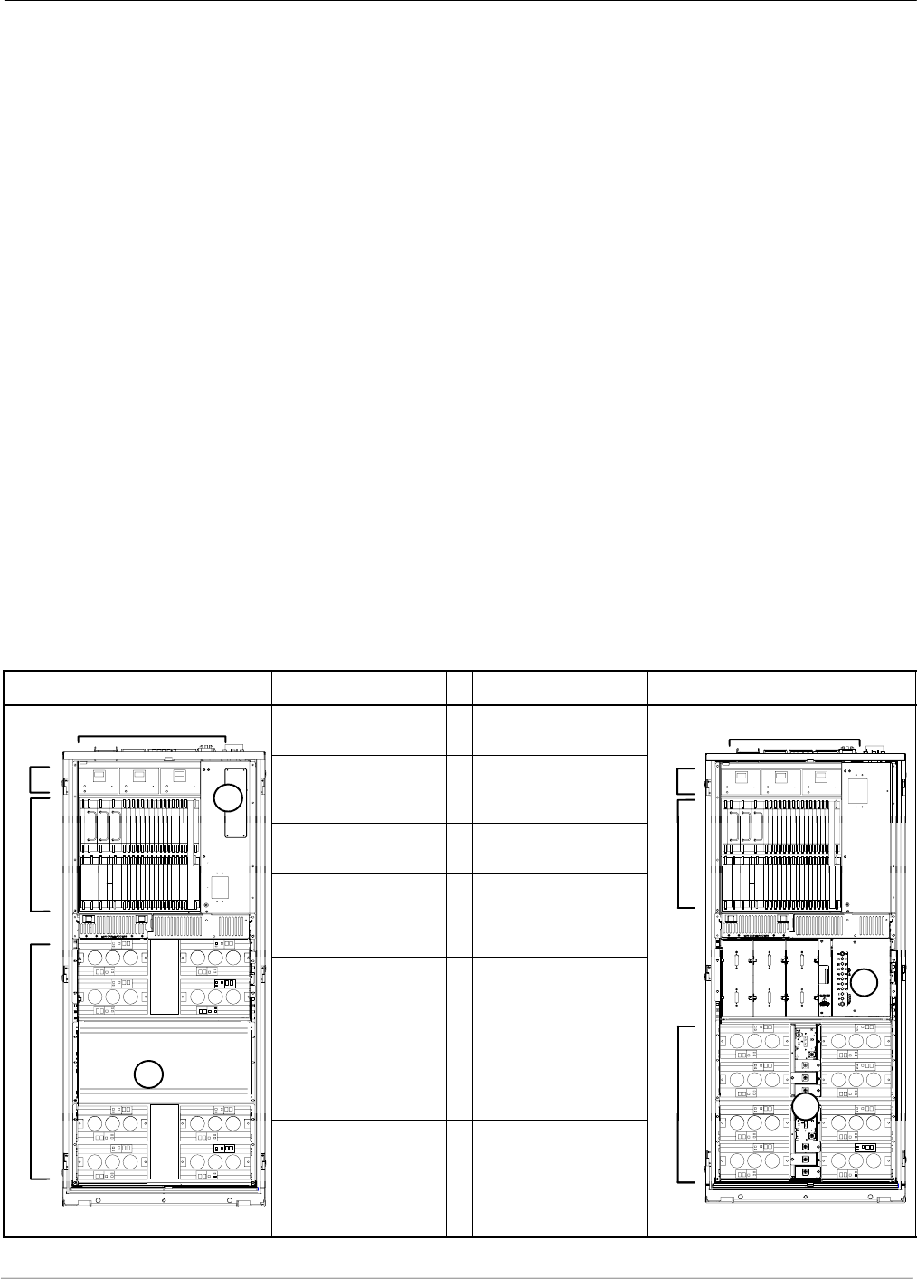
An overview of the BTS differences is illustrated in the following table
and in illustrations on the following pages (Figure 1 thru Figure 4).
SC 4812T Description # Description SC 4812T-MC
1
23x3 DC Power Input
(see Figure 1) 12x2 DC Power Input
(see Figure 1) 1
2
7
3I/O Plate supporting
3x3 DC Power Input
(see Figure 2)
2I/O Plate supporting
2x2 DC Power Input
(see Figure 2)
3
4CCCP Fan Tray 3CCCP Speed
Controlled Fan Tray 4
C-CCP Cage:
SCIO (3- or 6-Sector)
SBBX-1X
SSwitch
4C-CCP Cage:
SMCIO (3- or 6-Sector)
SHigh Power BBX-1X
SHigh Power Switch
6
5
PA Shelves:
SSC 4812T LPA
S4x4 TX Backplane
SPA Location and
Mapping (see Figure 3)
5PA Shelves:
SSC 4812T CLPA
SMulticarrier module
SParallel PA Combiner
SEnhanced Trunking
Module
SLPA/PLC Filler Panel
SPA Location and
Mapping (see Figure 3) 56
7
2:1 or 4:1 Combiners or
Dual Bandpass TX
Filters
6TX Bandpass Filters
and/or
TX Output Terminator
5
ti-CDMA-WP-00098-v01-ildoc-ftw
PA Breaker Mapping
(see Figure 4) 7PA Breaker Mapping
(see Figure 4) ti-CDMA-WP-00196-v01-ildoc-ftw
SC 4812T-MC vs SC 4812T BTS Read Me First (Comparison) 68P64115A19–4
Mar 20031X SC 4812T-MC BTS Hardware Installation - Software Release R2.16.1.x
CONTROLLED INTRODUCTION
RMF-2
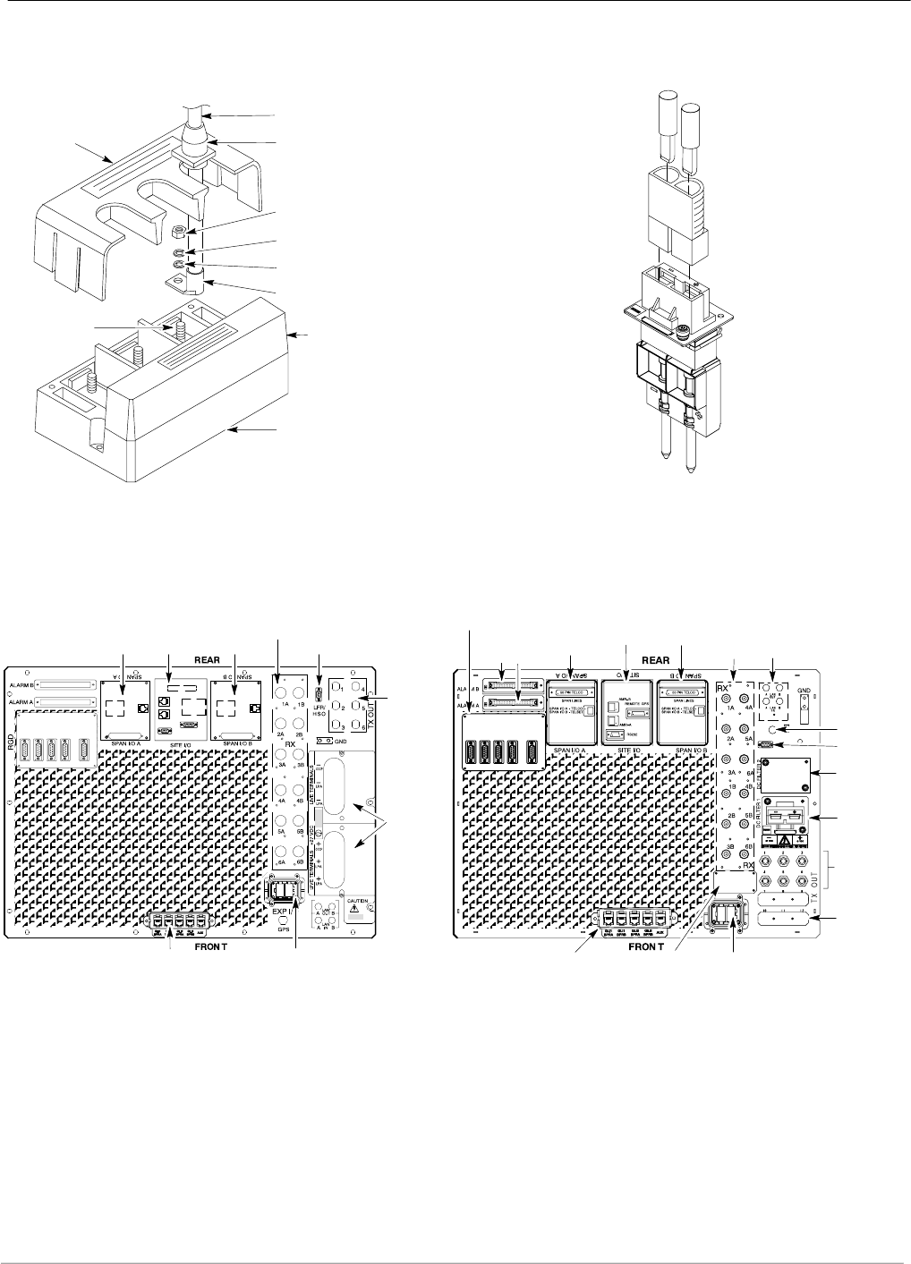
Figure 1: DC Power Input Connector Comparison
SC 4812T SC 4812T–MC
CABLE
GROMMET
(0509591Y02)
LUG COVER
(1509789V01)
M10 NUT
(0210971A09)
M10 LOCK WASHER
(0410985A02)
M10 FLAT WASHER
(0410983B28)
CRIMP LUG
FEED COVER
(DO NOT REMOVE)
ENCLOSURE
BASE
POWER
INPUT STUD
ti-CDMA-WP-00024-v01-ildoc-ftw
DC
CONTACT
Input
Connector/
DC Filter
ti-CDMA-WP-00074-v01-ildoc-ftw
DC
Connector
Housing
DC
CONTACT
(+) DC CABLE
DC CABLE (–)
(–)
(+)
Figure 2: I/O Plate Comparison
ETHERNET ROUTER (IF USED;
OTHERWISE, FILLER PLATE) EXP IN FILLER
PLATE RF EXPANSION PORT TO ANOTHER
BTS (USED ONLY IF EXPANSION
FRAME INSTALLED; OTHERWISE,
FILLER PLATE INSTALLED)
ti-CDMA-WP-00188-v01-ildoc-ftw
SPAN I/O
SITE I/O
ALARM
CONNECTORS
LAN
CONNECTIONS
GPS IN
HSO/LFR
FILLER PLATE
RECEIVE
ANTENNA
CONNECTORS
INPUT
CONNECTOR/
DC FILTER
SPAN I/O
REMOTE GPS DISTRIBUTION (RGD) MODULE –
USED ONLY IF EXPANSION FRAME(S) INSTALLED
PACKET
BACKHAUL PORTS RF EXPANSION PORT
(TO ANOTHER BTS)
LOW FREQUENCY
RECEIVER / HSO
SPAN I/O
TRANSMIT
ANTENNA
CONNECTORS
POWER
INPUT
RECEIVE ANTENNA
CONNECTORS
SITE I/OSPAN I/O
ti-CDMA-WP-00101-v01-ildoc-ftw
SC 4812T SC 4812T–MC
3 to 6 TX
ANTENNA
CONNECTORS
(depending on
configuration)
2 to 3 TX
ANTENNA
FILLER PLATES
(depending on
configuration)
SC 4812T-MC vs SC 4812T BTS Read Me First (Comparison)
68P64115A19–4
Mar 2003 1X SC 4812T-MC BTS Hardware Installation - Software Release R2.16.1.x
CONTROLLED INTRODUCTION
RMF-3
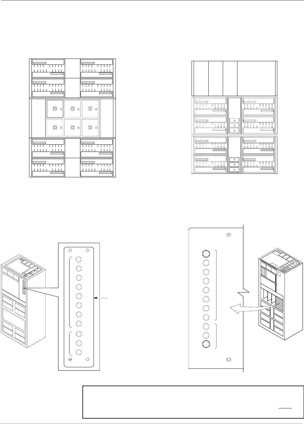
Figure 3: PA Location Comparison
Numbering
LPA 1A
LPA 1B
LPA 1C
LPA 1D
LPA 3C
LPA 3A
LPA 3B
LPA 3D
LPA 2D
LPA 2C
LPA 2B
LPA 2A
LPA 4B
LPA 4A
LPA 4C
LPA 4D
Sector
3 Sector
Sector
3 Sector
(6 Sector)
Numbering
2 to 1 Combiner
3 Sector or 6 Sector
C1, S1–3
(C1, S1–3) C2, S1–3
(C2, S1–3)
C3, S1–3
(C1, S4–6) C4, S1–3
(C2, S4–6)
(6 Sector)
123
456
1C
2C
3C
4C
1D
2D
3D
4D
3A
2A
1A 1B
2B
3B
4B
C1 (C1)
C2 (C2)
C3 (C1)
C4 (C2)
C1 (C1)
C2 (C2)
C3 (C1)
C4 (C2)
C1 (C1)
C2 (C2)
C3 (C1)
C4 (C2)
C1 (C1)
C2 (C2)
C3 (C1)
C4 (C2)
4A
S4
MCM
1
Carrier
Numbering Carrier
Numbering
3 Sector and 6 Sector 3 Sector
(6 Sector)
3 Sector
(6 Sector)
S5
S6
S1
S2
S3
MCM
2
CLPACLPA
CLPA
CLPA
CLPA
CLPA
CLPA
CLPA
CLPA
CLPA
CLPA
CLPA
CLPA
CLPA
CLPA
CLPA
ti-CDMA-WP-00197-v01-ildoc-ftw
SC 4812T SC 4812T–MC
FW00297 REF.
Figure 4: PA Breaker Mapping Comparison
50
SC 4812T SC4812T–MC
L
P
A
C
C
C
P
2A
4A
2B
4B
2C
4C
2D
4D
1A
3A
1B
3B
1C
3C
1D
3D
50
1
2
3
50 50 50 50 50 50 50 50 50
ti-CDMA-WP-00224-v01-ildoc-ftw
CIRCUIT
BREAKER
PANEL
1D
1C
2C 2D
1B
1A
2A 2B
30
30
30
30
30
30
30
30
3D
3C
4C 4D
3B
3A
4A 4B
50
50
50
1
2
3
C
C
P
L
P
A
C
FW00380 REF.
NOTE IMPORTANT: A breaker supports a pair of PAs. In
SC4812T–MC, disengaging (pulling) a PA breaker while the
BTS is operational will degrade the TX Output power of ALL
sector–carriers, not just a specific carrier as in SC4812T.

SC 4812T-MC vs SC 4812T BTS Read Me First (Comparison) 68P64115A19–4
Mar 20031X SC 4812T-MC BTS Hardware Installation - Software Release R2.16.1.x
CONTROLLED INTRODUCTION
RMF-4
Notes

1X SC 4812T-MC BTS Hardware Installation - Software Release R2.16.1.x
CONTROLLED INTRODUCTION
i
Mar 2003
Table of Contents
.
.
.

Table of Contents 68P64115A19–4
1X SC 4812T-MC BTS Hardware Installation - Software Release R2.16.1.x
CONTROLLED INTRODUCTION
ii Mar 2003
SC 4812T-MC vs SC 4812T BTS Read Me First (Comparison) RMF-2 . . . . . . . . . . . . . . . . . . . . . . . . . . . . . . . . . . . .
Contents
FCC Requirements xi . . . . . . . . . . . . . . . . . . . . . . . . . . . . . . . . . . . . . . . . . . . . . . . . . . . . . . . . . . . . . . . . . . . . . . . . . .
Content xi . . . . . . . . . . . . . . . . . . . . . . . . . . . . . . . . . . . . . . . . . . . . . . . . . . . . . . . . . . . . . . . . . . . . . . . . . . . . .
FCC Part 15 Requirements xi . . . . . . . . . . . . . . . . . . . . . . . . . . . . . . . . . . . . . . . . . . . . . . . . . . . . . . . . . . . .
FCC Part 68 Requirements xii . . . . . . . . . . . . . . . . . . . . . . . . . . . . . . . . . . . . . . . . . . . . . . . . . . . . . . . . . . . .
Foreword xiii . . . . . . . . . . . . . . . . . . . . . . . . . . . . . . . . . . . . . . . . . . . . . . . . . . . . . . . . . . . . . . . . . . . . . . . . . . . . . . . . . . .
General Safety xv . . . . . . . . . . . . . . . . . . . . . . . . . . . . . . . . . . . . . . . . . . . . . . . . . . . . . . . . . . . . . . . . . . . . . . . . . . . . . .
Revision History xvii . . . . . . . . . . . . . . . . . . . . . . . . . . . . . . . . . . . . . . . . . . . . . . . . . . . . . . . . . . . . . . . . . . . . . . . . . . . . .
Chapter 1 Manual Overview and BTS General Information 1-1 . . . . . . . . . . . . . . . . . . .
Manual Overview, Abbreviations and Acronyms 1-2 . . . . . . . . . . . . . . . . . . . . . . . . . . . . . . . . . . . . . . . . . . . . . . . . .
Manual Overview 1-2 . . . . . . . . . . . . . . . . . . . . . . . . . . . . . . . . . . . . . . . . . . . . . . . . . . . . . . . . . . . . . . . . . . . . .
Manual Structure 1-2 . . . . . . . . . . . . . . . . . . . . . . . . . . . . . . . . . . . . . . . . . . . . . . . . . . . . . . . . . . . . . . . . . . . . .
Abbreviations and Acronyms 1-3 . . . . . . . . . . . . . . . . . . . . . . . . . . . . . . . . . . . . . . . . . . . . . . . . . . . . . . . . . . .
Required Documentation and Environmental Specifications 1-5 . . . . . . . . . . . . . . . . . . . . . . . . . . . . . . . . . . . . . . .
Required Documentation 1-5 . . . . . . . . . . . . . . . . . . . . . . . . . . . . . . . . . . . . . . . . . . . . . . . . . . . . . . . . . . . . . .
Specifications 1-6 . . . . . . . . . . . . . . . . . . . . . . . . . . . . . . . . . . . . . . . . . . . . . . . . . . . . . . . . . . . . . . . . . . . . . . . .
BTS Frame Site Layout 1-7 . . . . . . . . . . . . . . . . . . . . . . . . . . . . . . . . . . . . . . . . . . . . . . . . . . . . . . . . . . . . . . . . . . . . . .
Base Transceiver Station (BTS) Frame Identification 1-8 . . . . . . . . . . . . . . . . . . . . . . . . . . . . . . . . . . . . . . . . . . . . .
BTS Frame 1-8 . . . . . . . . . . . . . . . . . . . . . . . . . . . . . . . . . . . . . . . . . . . . . . . . . . . . . . . . . . . . . . . . . . . . . . . . . .
I/O Plate 1-9 . . . . . . . . . . . . . . . . . . . . . . . . . . . . . . . . . . . . . . . . . . . . . . . . . . . . . . . . . . . . . . . . . . . . . . . . . . . .
Site I/O 1-9 . . . . . . . . . . . . . . . . . . . . . . . . . . . . . . . . . . . . . . . . . . . . . . . . . . . . . . . . . . . . . . . . . . . . . . . . . . . . .
Span I/O 1-9 . . . . . . . . . . . . . . . . . . . . . . . . . . . . . . . . . . . . . . . . . . . . . . . . . . . . . . . . . . . . . . . . . . . . . . . . . . . .
Combined CDMA Channel Processor (C-CCP) Shelf 1-9 . . . . . . . . . . . . . . . . . . . . . . . . . . . . . . . . . . . . . .
Power Distribution Cage MC Configuration 1-10 . . . . . . . . . . . . . . . . . . . . . . . . . . . . . . . . . . . . . . . . . . . . . .
MC CLPA Cage 1-10 . . . . . . . . . . . . . . . . . . . . . . . . . . . . . . . . . . . . . . . . . . . . . . . . . . . . . . . . . . . . . . . . . . . . . .
MC Module 1-10 . . . . . . . . . . . . . . . . . . . . . . . . . . . . . . . . . . . . . . . . . . . . . . . . . . . . . . . . . . . . . . . . . . . . . . . . . .
In-Frame Components 1-10 . . . . . . . . . . . . . . . . . . . . . . . . . . . . . . . . . . . . . . . . . . . . . . . . . . . . . . . . . . . . . . . .
External Components 1-10 . . . . . . . . . . . . . . . . . . . . . . . . . . . . . . . . . . . . . . . . . . . . . . . . . . . . . . . . . . . . . . . . .
Chapter 2 Inter-Frame Cabling 2-1 . . . . . . . . . . . . . . . . . . . . . . . . . . . . . . . . . . . . . . . . . . . . .
Inter-Frame Cabling 2-2 . . . . . . . . . . . . . . . . . . . . . . . . . . . . . . . . . . . . . . . . . . . . . . . . . . . . . . . . . . . . . . . . . . . . . . . . .
Overview 2-2 . . . . . . . . . . . . . . . . . . . . . . . . . . . . . . . . . . . . . . . . . . . . . . . . . . . . . . . . . . . . . . . . . . . . . . . . . . . .
Review the Material 2-2 . . . . . . . . . . . . . . . . . . . . . . . . . . . . . . . . . . . . . . . . . . . . . . . . . . . . . . . . . . . . . . . . . .
Configurations Supported 2-2 . . . . . . . . . . . . . . . . . . . . . . . . . . . . . . . . . . . . . . . . . . . . . . . . . . . . . . . . . . . . .
Cabling Installation Order 2-2 . . . . . . . . . . . . . . . . . . . . . . . . . . . . . . . . . . . . . . . . . . . . . . . . . . . . . . . . . . . . .
Cable Labels 2-2 . . . . . . . . . . . . . . . . . . . . . . . . . . . . . . . . . . . . . . . . . . . . . . . . . . . . . . . . . . . . . . . . . . . . . . . .
Cable Connections 2-3 . . . . . . . . . . . . . . . . . . . . . . . . . . . . . . . . . . . . . . . . . . . . . . . . . . . . . . . . . . . . . . . . . . . . . . . . . .
BTS Frame Description 2-3 . . . . . . . . . . . . . . . . . . . . . . . . . . . . . . . . . . . . . . . . . . . . . . . . . . . . . . . . . . . . . . .
Top I/O (Interconnect) Plate (Figure 2-1 and Figure 2-2) 2-3 . . . . . . . . . . . . . . . . . . . . . . . . . . . . . . . . . . .
Expansion Frame I/O Plate 2-5 . . . . . . . . . . . . . . . . . . . . . . . . . . . . . . . . . . . . . . . . . . . . . . . . . . . . . . . . . . . .
Site I/O and Span I/O Boards 2-6 . . . . . . . . . . . . . . . . . . . . . . . . . . . . . . . . . . . . . . . . . . . . . . . . . . . . . . . . . .
Remote GPS Distribution (RGD) Card 2-6 . . . . . . . . . . . . . . . . . . . . . . . . . . . . . . . . . . . . . . . . . . . . . . . . . .
Cabling Diagrams and Descriptions 2-7 . . . . . . . . . . . . . . . . . . . . . . . . . . . . . . . . . . . . . . . . . . . . . . . . . . . . . . . . . . . .
Cable Descriptions and Part Numbers 2-7 . . . . . . . . . . . . . . . . . . . . . . . . . . . . . . . . . . . . . . . . . . . . . . . . . . .
Overall Cabling Diagram (Single Frame) 2-9 . . . . . . . . . . . . . . . . . . . . . . . . . . . . . . . . . . . . . . . . . . . . . . . . .
Alarm / Span Cabling 2-10 . . . . . . . . . . . . . . . . . . . . . . . . . . . . . . . . . . . . . . . . . . . . . . . . . . . . . . . . . . . . . . . . . . . . . . . .
Objective 2-10 . . . . . . . . . . . . . . . . . . . . . . . . . . . . . . . . . . . . . . . . . . . . . . . . . . . . . . . . . . . . . . . . . . . . . . . . . . . .

Table of Contents
68P64115A19–4
1X SC 4812T-MC BTS Hardware Installation - Software Release R2.16.1.x
CONTROLLED INTRODUCTION
iii
Mar 2003
Cable Labels 2-10 . . . . . . . . . . . . . . . . . . . . . . . . . . . . . . . . . . . . . . . . . . . . . . . . . . . . . . . . . . . . . . . . . . . . . . . .
Equipment Needed 2-10 . . . . . . . . . . . . . . . . . . . . . . . . . . . . . . . . . . . . . . . . . . . . . . . . . . . . . . . . . . . . . . . . . . .
Cabling Diagram 2-11 . . . . . . . . . . . . . . . . . . . . . . . . . . . . . . . . . . . . . . . . . . . . . . . . . . . . . . . . . . . . . . . . . . . . .
Cable Run List 2-11 . . . . . . . . . . . . . . . . . . . . . . . . . . . . . . . . . . . . . . . . . . . . . . . . . . . . . . . . . . . . . . . . . . . . . . .
Install Span and Alarm Cables 2-12 . . . . . . . . . . . . . . . . . . . . . . . . . . . . . . . . . . . . . . . . . . . . . . . . . . . . . . . . .
Alarm Signal Specifications 2-13 . . . . . . . . . . . . . . . . . . . . . . . . . . . . . . . . . . . . . . . . . . . . . . . . . . . . . . . . . . . .
Span Line Cable Pin Numbering 2-14 . . . . . . . . . . . . . . . . . . . . . . . . . . . . . . . . . . . . . . . . . . . . . . . . . . . . . . . .
Alarm Connectors Pin and Signal Information 2-15 . . . . . . . . . . . . . . . . . . . . . . . . . . . . . . . . . . . . . . . . . . . .
Equipment Compliance 2-18 . . . . . . . . . . . . . . . . . . . . . . . . . . . . . . . . . . . . . . . . . . . . . . . . . . . . . . . . . . . . . . . . . . . . . . .
BTS System Timing Options 2-19 . . . . . . . . . . . . . . . . . . . . . . . . . . . . . . . . . . . . . . . . . . . . . . . . . . . . . . . . . . . . . . . . . .
Timing Sources 2-19 . . . . . . . . . . . . . . . . . . . . . . . . . . . . . . . . . . . . . . . . . . . . . . . . . . . . . . . . . . . . . . . . . . . . . .
RF Global Positioning Satellite (RF GPS) Cabling 2-20 . . . . . . . . . . . . . . . . . . . . . . . . . . . . . . . . . . . . . . . . . . . . . . . .
RF GPS Cabling Diagram 2-20 . . . . . . . . . . . . . . . . . . . . . . . . . . . . . . . . . . . . . . . . . . . . . . . . . . . . . . . . . . . . .
Cable Run List 2-21 . . . . . . . . . . . . . . . . . . . . . . . . . . . . . . . . . . . . . . . . . . . . . . . . . . . . . . . . . . . . . . . . . . . . . . .
RF GPS Cabling Installation Procedure 2-21 . . . . . . . . . . . . . . . . . . . . . . . . . . . . . . . . . . . . . . . . . . . . . . . . .
Remote Global Positioning Satellite (RGPS) Cabling 2-22 . . . . . . . . . . . . . . . . . . . . . . . . . . . . . . . . . . . . . . . . . . . . .
RGPS Cabling Diagrams 2-22 . . . . . . . . . . . . . . . . . . . . . . . . . . . . . . . . . . . . . . . . . . . . . . . . . . . . . . . . . . . . . .
Cabling Run List 2-23 . . . . . . . . . . . . . . . . . . . . . . . . . . . . . . . . . . . . . . . . . . . . . . . . . . . . . . . . . . . . . . . . . . . . .
Install RGPS Cable 2-23 . . . . . . . . . . . . . . . . . . . . . . . . . . . . . . . . . . . . . . . . . . . . . . . . . . . . . . . . . . . . . . . . . . .
Low Frequency Receiver / High Stability Oscillator (LFR/HSO) Cabling 2-24 . . . . . . . . . . . . . . . . . . . . . . . . . . . . .
Overview 2-24 . . . . . . . . . . . . . . . . . . . . . . . . . . . . . . . . . . . . . . . . . . . . . . . . . . . . . . . . . . . . . . . . . . . . . . . . . . . .
Cable Labels 2-24 . . . . . . . . . . . . . . . . . . . . . . . . . . . . . . . . . . . . . . . . . . . . . . . . . . . . . . . . . . . . . . . . . . . . . . . .
Cable Run List 2-24 . . . . . . . . . . . . . . . . . . . . . . . . . . . . . . . . . . . . . . . . . . . . . . . . . . . . . . . . . . . . . . . . . . . . . . .
Procedure 2-24 . . . . . . . . . . . . . . . . . . . . . . . . . . . . . . . . . . . . . . . . . . . . . . . . . . . . . . . . . . . . . . . . . . . . . . . . . . .
LFR Cable (Cable L) Pin/Signal Information 2-25 . . . . . . . . . . . . . . . . . . . . . . . . . . . . . . . . . . . . . . . . . . . . . .
BTS Antenna Configuration 2-26 . . . . . . . . . . . . . . . . . . . . . . . . . . . . . . . . . . . . . . . . . . . . . . . . . . . . . . . . . . . . . . . . . . .
Overview 2-26 . . . . . . . . . . . . . . . . . . . . . . . . . . . . . . . . . . . . . . . . . . . . . . . . . . . . . . . . . . . . . . . . . . . . . . . . . . . .
RX Antenna Configurations 2-26 . . . . . . . . . . . . . . . . . . . . . . . . . . . . . . . . . . . . . . . . . . . . . . . . . . . . . . . . . . . .
TX Antenna Configurations 2-27 . . . . . . . . . . . . . . . . . . . . . . . . . . . . . . . . . . . . . . . . . . . . . . . . . . . . . . . . . . . .
BTS 60 Degree Sector (6 Sector) Transmit Path Cabling 2-28 . . . . . . . . . . . . . . . . . . . . . . . . . . . . . . . . . . . . . . . . .
Objective 2-28 . . . . . . . . . . . . . . . . . . . . . . . . . . . . . . . . . . . . . . . . . . . . . . . . . . . . . . . . . . . . . . . . . . . . . . . . . . . .
Cable Labels 2-28 . . . . . . . . . . . . . . . . . . . . . . . . . . . . . . . . . . . . . . . . . . . . . . . . . . . . . . . . . . . . . . . . . . . . . . . .
Cabling Diagram 2-28 . . . . . . . . . . . . . . . . . . . . . . . . . . . . . . . . . . . . . . . . . . . . . . . . . . . . . . . . . . . . . . . . . . . . .
60 Degree Sector Configuration 2-30 . . . . . . . . . . . . . . . . . . . . . . . . . . . . . . . . . . . . . . . . . . . . . . . . . . . . . . . .
TX Ports for 6 Sector Configuration 2-30 . . . . . . . . . . . . . . . . . . . . . . . . . . . . . . . . . . . . . . . . . . . . . . . . . . . . .
Procedure 2-30 . . . . . . . . . . . . . . . . . . . . . . . . . . . . . . . . . . . . . . . . . . . . . . . . . . . . . . . . . . . . . . . . . . . . . . . . . . .
BTS 60 Degree Sector (6 Sector) Receive Path Cabling 2-31 . . . . . . . . . . . . . . . . . . . . . . . . . . . . . . . . . . . . . . . . . .
Objective 2-31 . . . . . . . . . . . . . . . . . . . . . . . . . . . . . . . . . . . . . . . . . . . . . . . . . . . . . . . . . . . . . . . . . . . . . . . . . . . .
Cable Labels 2-31 . . . . . . . . . . . . . . . . . . . . . . . . . . . . . . . . . . . . . . . . . . . . . . . . . . . . . . . . . . . . . . . . . . . . . . . .
Cabling Diagram 2-31 . . . . . . . . . . . . . . . . . . . . . . . . . . . . . . . . . . . . . . . . . . . . . . . . . . . . . . . . . . . . . . . . . . . . .
Procedure 2-32 . . . . . . . . . . . . . . . . . . . . . . . . . . . . . . . . . . . . . . . . . . . . . . . . . . . . . . . . . . . . . . . . . . . . . . . . . . .
BTS 120 Degree Sector (3 Sector) Transmit Path Cabling 2-33 . . . . . . . . . . . . . . . . . . . . . . . . . . . . . . . . . . . . . . . .
Objective 2-33 . . . . . . . . . . . . . . . . . . . . . . . . . . . . . . . . . . . . . . . . . . . . . . . . . . . . . . . . . . . . . . . . . . . . . . . . . . . .
Cable Labels 2-33 . . . . . . . . . . . . . . . . . . . . . . . . . . . . . . . . . . . . . . . . . . . . . . . . . . . . . . . . . . . . . . . . . . . . . . . .
Cabling Diagram 2-33 . . . . . . . . . . . . . . . . . . . . . . . . . . . . . . . . . . . . . . . . . . . . . . . . . . . . . . . . . . . . . . . . . . . . .
Procedure 2-35 . . . . . . . . . . . . . . . . . . . . . . . . . . . . . . . . . . . . . . . . . . . . . . . . . . . . . . . . . . . . . . . . . . . . . . . . . . .
BTS 120 Degree Sector (3 Sector) Receive Path Cabling 2-36 . . . . . . . . . . . . . . . . . . . . . . . . . . . . . . . . . . . . . . . . .
Objective 2-36 . . . . . . . . . . . . . . . . . . . . . . . . . . . . . . . . . . . . . . . . . . . . . . . . . . . . . . . . . . . . . . . . . . . . . . . . . . . .
Cable Labels 2-36 . . . . . . . . . . . . . . . . . . . . . . . . . . . . . . . . . . . . . . . . . . . . . . . . . . . . . . . . . . . . . . . . . . . . . . . .
Cabling Diagram 2-36 . . . . . . . . . . . . . . . . . . . . . . . . . . . . . . . . . . . . . . . . . . . . . . . . . . . . . . . . . . . . . . . . . . . . .
Cabling Procedure 2-38 . . . . . . . . . . . . . . . . . . . . . . . . . . . . . . . . . . . . . . . . . . . . . . . . . . . . . . . . . . . . . . . . . . .

Table of Contents 68P64115A19–4
1X SC 4812T-MC BTS Hardware Installation - Software Release R2.16.1.x
CONTROLLED INTRODUCTION
iv Mar 2003
Earth Ground Cabling 2-39 . . . . . . . . . . . . . . . . . . . . . . . . . . . . . . . . . . . . . . . . . . . . . . . . . . . . . . . . . . . . . . . . . . . . . . . .
Objective 2-39 . . . . . . . . . . . . . . . . . . . . . . . . . . . . . . . . . . . . . . . . . . . . . . . . . . . . . . . . . . . . . . . . . . . . . . . . . . . .
Earth Grounding Diagram 2-39 . . . . . . . . . . . . . . . . . . . . . . . . . . . . . . . . . . . . . . . . . . . . . . . . . . . . . . . . . . . . .
Cable Labels 2-39 . . . . . . . . . . . . . . . . . . . . . . . . . . . . . . . . . . . . . . . . . . . . . . . . . . . . . . . . . . . . . . . . . . . . . . . .
Equipment Needed 2-39 . . . . . . . . . . . . . . . . . . . . . . . . . . . . . . . . . . . . . . . . . . . . . . . . . . . . . . . . . . . . . . . . . . .
Install Earth Grounding Cables 2-40 . . . . . . . . . . . . . . . . . . . . . . . . . . . . . . . . . . . . . . . . . . . . . . . . . . . . . . . . .
BTS Power Cabling 2-41 . . . . . . . . . . . . . . . . . . . . . . . . . . . . . . . . . . . . . . . . . . . . . . . . . . . . . . . . . . . . . . . . . . . . . . . . . .
Objective 2-41 . . . . . . . . . . . . . . . . . . . . . . . . . . . . . . . . . . . . . . . . . . . . . . . . . . . . . . . . . . . . . . . . . . . . . . . . . . . .
Important Guidelines 2-41 . . . . . . . . . . . . . . . . . . . . . . . . . . . . . . . . . . . . . . . . . . . . . . . . . . . . . . . . . . . . . . . . . .
Option A. Power Distribution Cabling for +27 V BTS Configuration with One Power Feed 2-44 . . . . . .
Option B. Power Distribution Cabling for +27 V BTS Configuration with Two Power Feeds 2-45 . . . . .
Tools and Equipment Required 2-46 . . . . . . . . . . . . . . . . . . . . . . . . . . . . . . . . . . . . . . . . . . . . . . . . . . . . . . . . .
Pre-connection Checklist 2-47 . . . . . . . . . . . . . . . . . . . . . . . . . . . . . . . . . . . . . . . . . . . . . . . . . . . . . . . . . . . . . .
Installing Power Cables 2-47 . . . . . . . . . . . . . . . . . . . . . . . . . . . . . . . . . . . . . . . . . . . . . . . . . . . . . . . . . . . . . . .
BTS Power Cabling 2-48 . . . . . . . . . . . . . . . . . . . . . . . . . . . . . . . . . . . . . . . . . . . . . . . . . . . . . . . . . . . . . . . . . . . . . . . . . .
Chapter 3 Expansion Frame Cabling and Installation 3-1 . . . . . . . . . . . . . . . . . . . . . . . .
Expansion Frame (+27 V BTS Configuration) 3-2 . . . . . . . . . . . . . . . . . . . . . . . . . . . . . . . . . . . . . . . . . . . . . . . . . . .
Installation Procedures 3-2 . . . . . . . . . . . . . . . . . . . . . . . . . . . . . . . . . . . . . . . . . . . . . . . . . . . . . . . . . . . . . . . .
Inter-frame Cables 3-2 . . . . . . . . . . . . . . . . . . . . . . . . . . . . . . . . . . . . . . . . . . . . . . . . . . . . . . . . . . . . . . . . . . .
Before You Begin 3-2 . . . . . . . . . . . . . . . . . . . . . . . . . . . . . . . . . . . . . . . . . . . . . . . . . . . . . . . . . . . . . . . . . . . .
Expansion Frame and Expansion I/O Plate 3-3 . . . . . . . . . . . . . . . . . . . . . . . . . . . . . . . . . . . . . . . . . . . . . .
Cable Labels 3-6 . . . . . . . . . . . . . . . . . . . . . . . . . . . . . . . . . . . . . . . . . . . . . . . . . . . . . . . . . . . . . . . . . . . . . . . .
Expansion Frame Cabling Diagram 3-6 . . . . . . . . . . . . . . . . . . . . . . . . . . . . . . . . . . . . . . . . . . . . . . . . . . . . .
Expansion Frame Inter-Frame Cabling 3-7 . . . . . . . . . . . . . . . . . . . . . . . . . . . . . . . . . . . . . . . . . . . . . . . . . . . . . . . . .
Remote GPS Distribution (RGD) Board Diagram 3-7 . . . . . . . . . . . . . . . . . . . . . . . . . . . . . . . . . . . . . . . . .
Expansion of the +27 V Frame 3-8 . . . . . . . . . . . . . . . . . . . . . . . . . . . . . . . . . . . . . . . . . . . . . . . . . . . . . . . . . . . . . . . .
Antenna Sharing 3-8 . . . . . . . . . . . . . . . . . . . . . . . . . . . . . . . . . . . . . . . . . . . . . . . . . . . . . . . . . . . . . . . . . . . . .
Tools Required 3-8 . . . . . . . . . . . . . . . . . . . . . . . . . . . . . . . . . . . . . . . . . . . . . . . . . . . . . . . . . . . . . . . . . . . . . . .
Expansion Procedure 3-8 . . . . . . . . . . . . . . . . . . . . . . . . . . . . . . . . . . . . . . . . . . . . . . . . . . . . . . . . . . . . . . . . .
RF GPS Expansion Installation 3-10 . . . . . . . . . . . . . . . . . . . . . . . . . . . . . . . . . . . . . . . . . . . . . . . . . . . . . . . . . . . . . . . .
GPS Expansion 3-10 . . . . . . . . . . . . . . . . . . . . . . . . . . . . . . . . . . . . . . . . . . . . . . . . . . . . . . . . . . . . . . . . . . . . . .
Customer Equipment Considerations and System Constrains 3-10 . . . . . . . . . . . . . . . . . . . . . . . . . . . . . .
RF RGPS Expansion Installation Considerations 3-10 . . . . . . . . . . . . . . . . . . . . . . . . . . . . . . . . . . . . . . . . .
Remote GPS Distribution Expansion 3-12 . . . . . . . . . . . . . . . . . . . . . . . . . . . . . . . . . . . . . . . . . . . . . . . . . . . . . . . . . . .
Configuration 3-12 . . . . . . . . . . . . . . . . . . . . . . . . . . . . . . . . . . . . . . . . . . . . . . . . . . . . . . . . . . . . . . . . . . . . . . . .
Tools Required 3-12 . . . . . . . . . . . . . . . . . . . . . . . . . . . . . . . . . . . . . . . . . . . . . . . . . . . . . . . . . . . . . . . . . . . . . . .
Remote GPS (RGD) Expansion Procedure 3-12 . . . . . . . . . . . . . . . . . . . . . . . . . . . . . . . . . . . . . . . . . . . . . .
High Stability Oscillator Expansion (HSOX) 3-13 . . . . . . . . . . . . . . . . . . . . . . . . . . . . . . . . . . . . . . . . . . . . . . . . . . . . .
Configuration 3-13 . . . . . . . . . . . . . . . . . . . . . . . . . . . . . . . . . . . . . . . . . . . . . . . . . . . . . . . . . . . . . . . . . . . . . . . .
Tools Required 3-13 . . . . . . . . . . . . . . . . . . . . . . . . . . . . . . . . . . . . . . . . . . . . . . . . . . . . . . . . . . . . . . . . . . . . . . .
HSO Expansion Procedure 3-13 . . . . . . . . . . . . . . . . . . . . . . . . . . . . . . . . . . . . . . . . . . . . . . . . . . . . . . . . . . . .
Local Area Network (LAN) Expansion Installation 3-14 . . . . . . . . . . . . . . . . . . . . . . . . . . . . . . . . . . . . . . . . . . . . . . . .
Configuration 3-14 . . . . . . . . . . . . . . . . . . . . . . . . . . . . . . . . . . . . . . . . . . . . . . . . . . . . . . . . . . . . . . . . . . . . . . . .
Tools Required 3-14 . . . . . . . . . . . . . . . . . . . . . . . . . . . . . . . . . . . . . . . . . . . . . . . . . . . . . . . . . . . . . . . . . . . . . . .
Torque Specifications 3-14 . . . . . . . . . . . . . . . . . . . . . . . . . . . . . . . . . . . . . . . . . . . . . . . . . . . . . . . . . . . . . . . . .
LAN Expansion Installation Procedure 3-14 . . . . . . . . . . . . . . . . . . . . . . . . . . . . . . . . . . . . . . . . . . . . . . . . . .
Setting Frame C-CCP Shelf Configuration Switch 3-16 . . . . . . . . . . . . . . . . . . . . . . . . . . . . . . . . . . . . . . . . . . . . . . . .
Chapter 4 Optional Equipment 4-1 . . . . . . . . . . . . . . . . . . . . . . . . . . . . . . . . . . . . . . . . . . . . .
Optional BTS Equipment Identification 4-2 . . . . . . . . . . . . . . . . . . . . . . . . . . . . . . . . . . . . . . . . . . . . . . . . . . . . . . . . .

Table of Contents
68P64115A19–4
1X SC 4812T-MC BTS Hardware Installation - Software Release R2.16.1.x
CONTROLLED INTRODUCTION
v
Mar 2003
Overview 4-2 . . . . . . . . . . . . . . . . . . . . . . . . . . . . . . . . . . . . . . . . . . . . . . . . . . . . . . . . . . . . . . . . . . . . . . . . . . . .
Directional Couplers 4-2 . . . . . . . . . . . . . . . . . . . . . . . . . . . . . . . . . . . . . . . . . . . . . . . . . . . . . . . . . . . . . . . . . .
Duplex Directional Couplers (DDC) and Mounting Bracket 4-3 . . . . . . . . . . . . . . . . . . . . . . . . . . . . . . . . .
RFDS 4-4 . . . . . . . . . . . . . . . . . . . . . . . . . . . . . . . . . . . . . . . . . . . . . . . . . . . . . . . . . . . . . . . . . . . . . . . . . . . . . .
RF Interfaces 4-4 . . . . . . . . . . . . . . . . . . . . . . . . . . . . . . . . . . . . . . . . . . . . . . . . . . . . . . . . . . . . . . . . . . . . . . . .
RFDS Function 4-4 . . . . . . . . . . . . . . . . . . . . . . . . . . . . . . . . . . . . . . . . . . . . . . . . . . . . . . . . . . . . . . . . . . . . . .
RFDS Cabling to the BTS 4-6 . . . . . . . . . . . . . . . . . . . . . . . . . . . . . . . . . . . . . . . . . . . . . . . . . . . . . . . . . . . . .
BTS Antenna Configuration 4-7 . . . . . . . . . . . . . . . . . . . . . . . . . . . . . . . . . . . . . . . . . . . . . . . . . . . . . . . . . . . . . . . . . . .
Overview 4-7 . . . . . . . . . . . . . . . . . . . . . . . . . . . . . . . . . . . . . . . . . . . . . . . . . . . . . . . . . . . . . . . . . . . . . . . . . . . .
BTS 60 Degree Sector (6 Sector) Transmit Path Cabling 4-8 . . . . . . . . . . . . . . . . . . . . . . . . . . . . . . . . . . . . . . . . .
Objective 4-8 . . . . . . . . . . . . . . . . . . . . . . . . . . . . . . . . . . . . . . . . . . . . . . . . . . . . . . . . . . . . . . . . . . . . . . . . . . . .
Cable Labels 4-8 . . . . . . . . . . . . . . . . . . . . . . . . . . . . . . . . . . . . . . . . . . . . . . . . . . . . . . . . . . . . . . . . . . . . . . . .
Cabling Diagram 4-8 . . . . . . . . . . . . . . . . . . . . . . . . . . . . . . . . . . . . . . . . . . . . . . . . . . . . . . . . . . . . . . . . . . . . .
60 Degree Sector Configuration 4-9 . . . . . . . . . . . . . . . . . . . . . . . . . . . . . . . . . . . . . . . . . . . . . . . . . . . . . . . .
Procedure 4-9 . . . . . . . . . . . . . . . . . . . . . . . . . . . . . . . . . . . . . . . . . . . . . . . . . . . . . . . . . . . . . . . . . . . . . . . . . . .
BTS 60 Degree Sector (6 Sector) Receive Path Cabling 4-10 . . . . . . . . . . . . . . . . . . . . . . . . . . . . . . . . . . . . . . . . . .
Objective 4-10 . . . . . . . . . . . . . . . . . . . . . . . . . . . . . . . . . . . . . . . . . . . . . . . . . . . . . . . . . . . . . . . . . . . . . . . . . . . .
Cable Labels 4-10 . . . . . . . . . . . . . . . . . . . . . . . . . . . . . . . . . . . . . . . . . . . . . . . . . . . . . . . . . . . . . . . . . . . . . . . .
Cabling Diagram 4-10 . . . . . . . . . . . . . . . . . . . . . . . . . . . . . . . . . . . . . . . . . . . . . . . . . . . . . . . . . . . . . . . . . . . . .
Procedure 4-11 . . . . . . . . . . . . . . . . . . . . . . . . . . . . . . . . . . . . . . . . . . . . . . . . . . . . . . . . . . . . . . . . . . . . . . . . . . .
BTS 120 Degree Sector (3 Sector) Transmit Path Cabling 4-12 . . . . . . . . . . . . . . . . . . . . . . . . . . . . . . . . . . . . . . . .
Objective 4-12 . . . . . . . . . . . . . . . . . . . . . . . . . . . . . . . . . . . . . . . . . . . . . . . . . . . . . . . . . . . . . . . . . . . . . . . . . . . .
Cable Labels 4-12 . . . . . . . . . . . . . . . . . . . . . . . . . . . . . . . . . . . . . . . . . . . . . . . . . . . . . . . . . . . . . . . . . . . . . . . .
Cabling Diagram 4-12 . . . . . . . . . . . . . . . . . . . . . . . . . . . . . . . . . . . . . . . . . . . . . . . . . . . . . . . . . . . . . . . . . . . . .
Procedure 4-13 . . . . . . . . . . . . . . . . . . . . . . . . . . . . . . . . . . . . . . . . . . . . . . . . . . . . . . . . . . . . . . . . . . . . . . . . . . .
BTS 120 Degree Sector (3 Sector) Receive Path Cabling 4-14 . . . . . . . . . . . . . . . . . . . . . . . . . . . . . . . . . . . . . . . . .
Objective 4-14 . . . . . . . . . . . . . . . . . . . . . . . . . . . . . . . . . . . . . . . . . . . . . . . . . . . . . . . . . . . . . . . . . . . . . . . . . . . .
Cable Labels 4-14 . . . . . . . . . . . . . . . . . . . . . . . . . . . . . . . . . . . . . . . . . . . . . . . . . . . . . . . . . . . . . . . . . . . . . . . .
Cabling Diagram 4-14 . . . . . . . . . . . . . . . . . . . . . . . . . . . . . . . . . . . . . . . . . . . . . . . . . . . . . . . . . . . . . . . . . . . . .
Cabling Procedure 4-16 . . . . . . . . . . . . . . . . . . . . . . . . . . . . . . . . . . . . . . . . . . . . . . . . . . . . . . . . . . . . . . . . . . .
3 Sector Non–Duplexed Cabling 4-17 . . . . . . . . . . . . . . . . . . . . . . . . . . . . . . . . . . . . . . . . . . . . . . . . . . . . . . . . . . . . . . .
4-17 . . . . . . . . . . . . . . . . . . . . . . . . . . . . . . . . . . . . . . . . . . . . . . . . . . . . . . . . . . . . . . . . . . . . . . . . . . . . . . . . . . . .
Objective 4-17 . . . . . . . . . . . . . . . . . . . . . . . . . . . . . . . . . . . . . . . . . . . . . . . . . . . . . . . . . . . . . . . . . . . . . . . . . . . .
Cabling Diagram 4-17 . . . . . . . . . . . . . . . . . . . . . . . . . . . . . . . . . . . . . . . . . . . . . . . . . . . . . . . . . . . . . . . . . . . . .
3 Sector Duplexed 4-20 . . . . . . . . . . . . . . . . . . . . . . . . . . . . . . . . . . . . . . . . . . . . . . . . . . . . . . . . . . . . . . . . . . . . . . . . . . .
Objective 4-20 . . . . . . . . . . . . . . . . . . . . . . . . . . . . . . . . . . . . . . . . . . . . . . . . . . . . . . . . . . . . . . . . . . . . . . . . . . . .
Cabling Diagram 4-20 . . . . . . . . . . . . . . . . . . . . . . . . . . . . . . . . . . . . . . . . . . . . . . . . . . . . . . . . . . . . . . . . . . . . .
6 Sector Duplexed 4-22 . . . . . . . . . . . . . . . . . . . . . . . . . . . . . . . . . . . . . . . . . . . . . . . . . . . . . . . . . . . . . . . . . . . . . . . . . . .
Objective 4-22 . . . . . . . . . . . . . . . . . . . . . . . . . . . . . . . . . . . . . . . . . . . . . . . . . . . . . . . . . . . . . . . . . . . . . . . . . . . .
Cabling Diagram 4-22 . . . . . . . . . . . . . . . . . . . . . . . . . . . . . . . . . . . . . . . . . . . . . . . . . . . . . . . . . . . . . . . . . . . . .
Chapter 5 What’s Next and Site Cleanup 5-1 . . . . . . . . . . . . . . . . . . . . . . . . . . . . . . . . . . . .
What’s Next 5-2 . . . . . . . . . . . . . . . . . . . . . . . . . . . . . . . . . . . . . . . . . . . . . . . . . . . . . . . . . . . . . . . . . . . . . . . . . . . . . . . .
Introduction 5-2 . . . . . . . . . . . . . . . . . . . . . . . . . . . . . . . . . . . . . . . . . . . . . . . . . . . . . . . . . . . . . . . . . . . . . . . . .
Clean Up the Site 5-2 . . . . . . . . . . . . . . . . . . . . . . . . . . . . . . . . . . . . . . . . . . . . . . . . . . . . . . . . . . . . . . . . . . . .
Fill Out Checklist 5-2 . . . . . . . . . . . . . . . . . . . . . . . . . . . . . . . . . . . . . . . . . . . . . . . . . . . . . . . . . . . . . . . . . . . . .
Optimize the System 5-2 . . . . . . . . . . . . . . . . . . . . . . . . . . . . . . . . . . . . . . . . . . . . . . . . . . . . . . . . . . . . . . . . .
Site Cleanup 5-3 . . . . . . . . . . . . . . . . . . . . . . . . . . . . . . . . . . . . . . . . . . . . . . . . . . . . . . . . . . . . . . . . . . . . . . . . . . . . . . . .
Remove Protective Covering 5-3 . . . . . . . . . . . . . . . . . . . . . . . . . . . . . . . . . . . . . . . . . . . . . . . . . . . . . . . . . . .
Lighting Fixtures 5-3 . . . . . . . . . . . . . . . . . . . . . . . . . . . . . . . . . . . . . . . . . . . . . . . . . . . . . . . . . . . . . . . . . . . . .
Tools 5-3 . . . . . . . . . . . . . . . . . . . . . . . . . . . . . . . . . . . . . . . . . . . . . . . . . . . . . . . . . . . . . . . . . . . . . . . . . . . . . . .

Table of Contents 68P64115A19–4
1X SC 4812T-MC BTS Hardware Installation - Software Release R2.16.1.x
CONTROLLED INTRODUCTION
vi Mar 2003
Materials 5-3 . . . . . . . . . . . . . . . . . . . . . . . . . . . . . . . . . . . . . . . . . . . . . . . . . . . . . . . . . . . . . . . . . . . . . . . . . . . .
Remove Debris 5-3 . . . . . . . . . . . . . . . . . . . . . . . . . . . . . . . . . . . . . . . . . . . . . . . . . . . . . . . . . . . . . . . . . . . . . .
Environment 5-3 . . . . . . . . . . . . . . . . . . . . . . . . . . . . . . . . . . . . . . . . . . . . . . . . . . . . . . . . . . . . . . . . . . . . . . . . .
Installation Completion Checklist 5-4 . . . . . . . . . . . . . . . . . . . . . . . . . . . . . . . . . . . . . . . . . . . . . . . . . . . . . . . . . . . . . .
Directions 5-4 . . . . . . . . . . . . . . . . . . . . . . . . . . . . . . . . . . . . . . . . . . . . . . . . . . . . . . . . . . . . . . . . . . . . . . . . . . .
Installation Completion Checklist 5-4 . . . . . . . . . . . . . . . . . . . . . . . . . . . . . . . . . . . . . . . . . . . . . . . . . . . . . . .
Appendix A Carrier Add Instructions A-1 . . . . . . . . . . . . . . . . . . . . . . . . . . . . . . . . . . . . . . .
Carrier Add Instructions A-2 . . . . . . . . . . . . . . . . . . . . . . . . . . . . . . . . . . . . . . . . . . . . . . . . . . . . . . . . . . . . . . . . . . . . . .
Overview A-2 . . . . . . . . . . . . . . . . . . . . . . . . . . . . . . . . . . . . . . . . . . . . . . . . . . . . . . . . . . . . . . . . . . . . . . . . . . . .
Tool & Torque Requirements A-2 . . . . . . . . . . . . . . . . . . . . . . . . . . . . . . . . . . . . . . . . . . . . . . . . . . . . . . . . . . .
T– Options A-2 . . . . . . . . . . . . . . . . . . . . . . . . . . . . . . . . . . . . . . . . . . . . . . . . . . . . . . . . . . . . . . . . . . . . . . . . . .
Carrier Add Matrix (3 Sector) A-2 . . . . . . . . . . . . . . . . . . . . . . . . . . . . . . . . . . . . . . . . . . . . . . . . . . . . . . . . . .
Adding a Carrier (3 Sector) A-3 . . . . . . . . . . . . . . . . . . . . . . . . . . . . . . . . . . . . . . . . . . . . . . . . . . . . . . . . . . . .
Carrier Add (6 Sector) A-5 . . . . . . . . . . . . . . . . . . . . . . . . . . . . . . . . . . . . . . . . . . . . . . . . . . . . . . . . . . . . . . . .
Carrier Add Matrix (6 Sector) A-5 . . . . . . . . . . . . . . . . . . . . . . . . . . . . . . . . . . . . . . . . . . . . . . . . . . . . . . . . . .
Installing a Second Carrier A-5 . . . . . . . . . . . . . . . . . . . . . . . . . . . . . . . . . . . . . . . . . . . . . . . . . . . . . . . . . . . .
Index Index-1 . . . . . . . . . . . . . . . . . . . . . . . . . . . . . . . . . . . . . . . . . . . . . . . . . . . . . . . . . . . . . . . . . . . . .

Table of Contents
68P64115A19–4
1X SC 4812T-MC BTS Hardware Installation - Software Release R2.16.1.x
CONTROLLED INTRODUCTION
vii
Mar 2003
Figure 1: DC Power Input Connector Comparison RMF-3 . . . . . . . . . . . . . . . . . . . . . . . . . . . . . . . . . . . . . . . .
Figure 2: I/O Plate Comparison RMF-3 . . . . . . . . . . . . . . . . . . . . . . . . . . . . . . . . . . . . . . . . . . . . . . . . . . . . . . . .
Figure 3: PA Location Comparison RMF-4 . . . . . . . . . . . . . . . . . . . . . . . . . . . . . . . . . . . . . . . . . . . . . . . . . . . . . .
Figure 4: PA Breaker Mapping Comparison RMF-4 . . . . . . . . . . . . . . . . . . . . . . . . . . . . . . . . . . . . . . . . . . . . . .
List of Figures
Figure 1-1:Dimensions and Clearances for the BTS 1-7 . . . . . . . . . . . . . . . . . . . . . . . . . . . . . . . . . . . . . . .
Figure 1-2: SC 4812T–MC BTS Frame 1-8 . . . . . . . . . . . . . . . . . . . . . . . . . . . . . . . . . . . . . . . . . . . . . . . . . .
Figure 2-1: SC4812T–MC Starter Frame I/O Plate 2-4 . . . . . . . . . . . . . . . . . . . . . . . . . . . . . . . . . . . . . . . .
Figure 2-2: SC4812T–MC Expansion Frame I/O Plate 2-5 . . . . . . . . . . . . . . . . . . . . . . . . . . . . . . . . . . . . .
Figure 2-3: Site I/O and Span I/O Boards 2-6 . . . . . . . . . . . . . . . . . . . . . . . . . . . . . . . . . . . . . . . . . . . . . . . .
Figure 2-4: RGD Board Cables Connection 2-6 . . . . . . . . . . . . . . . . . . . . . . . . . . . . . . . . . . . . . . . . . . . . . .
Figure 2-5: Overall Signal Cabling Diagram for CDMA Systems 2-9 . . . . . . . . . . . . . . . . . . . . . . . . . . . .
Figure 2-6: Alarm and Span Line Cabling Details 2-11 . . . . . . . . . . . . . . . . . . . . . . . . . . . . . . . . . . . . . . . . .
Figure 2-7: Cable A (Span Line) Pin Numbering 2-14 . . . . . . . . . . . . . . . . . . . . . . . . . . . . . . . . . . . . . . . . . .
Figure 2-8: Cable B (Alarm) Pin Numbering 2-15 . . . . . . . . . . . . . . . . . . . . . . . . . . . . . . . . . . . . . . . . . . . . . .
Figure 2-9: RF GPS Cabling Detail 2-20 . . . . . . . . . . . . . . . . . . . . . . . . . . . . . . . . . . . . . . . . . . . . . . . . . . . . .
Figure 2-10: Remote GPS Mounting Detail 2-22 . . . . . . . . . . . . . . . . . . . . . . . . . . . . . . . . . . . . . . . . . . . . . .
Figure 2-11: Remote GPS Cabling Diagram 2-23 . . . . . . . . . . . . . . . . . . . . . . . . . . . . . . . . . . . . . . . . . . . . . .
Figure 2-12: 60 Degree Sector (6 Sector) Transmit Path Cabling Details (Outside Frame) 2-28 . . . . . .
Figure 2-13: 60 Degree Sector (6 Sector) Transmit Path Cabling Details (Inside frame) 2-29 . . . . . . . .
Figure 2-14: 60 Degree Sector (6 Sector) Receive Path Cabling Details 2-31 . . . . . . . . . . . . . . . . . . . . .
Figure 2-15: 120 Degree Sector (3 Sector) Transmit Path Cabling Details (outside the frame) 2-33 . . .
Figure 2-16: 120 Degree Sector (3 Sector) Transmit Path Cabling Details (inside the frame) 2-34 . . . .
Figure 2-17: 120 Degree Sector (3 Sector) Receive Path Cabling Details 2-37 . . . . . . . . . . . . . . . . . . . .
Figure 2-18: Earth Ground Cabling Details 2-39 . . . . . . . . . . . . . . . . . . . . . . . . . . . . . . . . . . . . . . . . . . . . . . .
Figure 2-19: Breaker Panel Identification 2-42 . . . . . . . . . . . . . . . . . . . . . . . . . . . . . . . . . . . . . . . . . . . . . . . .
Figure 2-20: Length and Tie-Down Requirements for BTS Power Cables 2-43 . . . . . . . . . . . . . . . . . . . . .
Figure 2-21: BTS Power Cabling for the +27 V BTS Configuration using One Power Feed 2-44 . . . . .
Figure 2-22: BTS Power Cabling for the + 27 V BTS Configuration using TwoPower Feeds 2-45 . . . . .
Figure 2-23: DC Power Connector/Filter 2-46 . . . . . . . . . . . . . . . . . . . . . . . . . . . . . . . . . . . . . . . . . . . . . . . . .
Figure 3-1:BTS MC Expansion Frame (+27 V Configuration) 3-3 . . . . . . . . . . . . . . . . . . . . . . . . . . . . . . .
Figure 3-2: Expansion Frame I/O Plate (+27 V Configuration) 3-4 . . . . . . . . . . . . . . . . . . . . . . . . . . . . . .
Figure 3-3: Starter Frame I/O Plate 3-5 . . . . . . . . . . . . . . . . . . . . . . . . . . . . . . . . . . . . . . . . . . . . . . . . . . . . .
Figure 3-4: Expansion Frame Cabling Details 3-6 . . . . . . . . . . . . . . . . . . . . . . . . . . . . . . . . . . . . . . . . . . . .
Figure 3-5: RGD Board Cable Connections 3-7 . . . . . . . . . . . . . . . . . . . . . . . . . . . . . . . . . . . . . . . . . . . . . .
Figure 3-6: RX Antenna Sharing with an Expansion Frame 3-8 . . . . . . . . . . . . . . . . . . . . . . . . . . . . . . . . .
Figure 3-7: System to Feed Multiple BTS’s from One RF GPS Antenna 3-11 . . . . . . . . . . . . . . . . . . . . . .
Figure 3-8: HSOX Cable (3086458H01) for Expansion Frame 3-13 . . . . . . . . . . . . . . . . . . . . . . . . . . . . . .
Figure 3-9: LAN Grounding Stud 3-15 . . . . . . . . . . . . . . . . . . . . . . . . . . . . . . . . . . . . . . . . . . . . . . . . . . . . . . .
Figure 3-10: Backplane DIP Switch Settings 3-16 . . . . . . . . . . . . . . . . . . . . . . . . . . . . . . . . . . . . . . . . . . . . .

Table of Contents 68P64115A19–4
1X SC 4812T-MC BTS Hardware Installation - Software Release R2.16.1.x
CONTROLLED INTRODUCTION
viii Mar 2003
Figure 4-1: Directional Couplers 4-2 . . . . . . . . . . . . . . . . . . . . . . . . . . . . . . . . . . . . . . . . . . . . . . . . . . . . . . . .
Figure 4-2: DDC (Duplexers – Directional Couplers) 4-3 . . . . . . . . . . . . . . . . . . . . . . . . . . . . . . . . . . . . . . .
Figure 4-3: RFDS (Rack Mount Unit) 4-5 . . . . . . . . . . . . . . . . . . . . . . . . . . . . . . . . . . . . . . . . . . . . . . . . . . . .
Figure 4-4: RFDS (Block Diagram) 4-6 . . . . . . . . . . . . . . . . . . . . . . . . . . . . . . . . . . . . . . . . . . . . . . . . . . . . .
Figure 4-5: 60 Degree Sector (6 Sector) Transmit Path Cabling Details 4-8 . . . . . . . . . . . . . . . . . . . . . .
Figure 4-6: 60 Degree Sector (6 Sector) Receive Path Cabling Details 4-10 . . . . . . . . . . . . . . . . . . . . . . .
Figure 4-7: 120 Degree Sector (3 Sector) Transmit Path Cabling Details 4-12 . . . . . . . . . . . . . . . . . . . . .
Figure 4-8: 120 Degree Sector (3 Sector) Receive Path Cabling Details 4-15 . . . . . . . . . . . . . . . . . . . . .
Figure 4-9: 3-Sector Non–Duplexed Cabling Configurations 4-18 . . . . . . . . . . . . . . . . . . . . . . . . . . . . . . . .
Figure 4-10: 3–Sector Duplexed Cabling Configurations 4-20 . . . . . . . . . . . . . . . . . . . . . . . . . . . . . . . . . . .
Figure 4-11: 6-Sector Duplexed Cabling Configurations 4-23 . . . . . . . . . . . . . . . . . . . . . . . . . . . . . . . . . . . .
Figure A-1: PLC Filler Plate Location (3X3 Enhanced Trunking Module) A-4 . . . . . . . . . . . . . . . . . . . . . .
Figure A-2: PLC Filler Plate Location (4X4 Enhanced Trunking Module) A-4 . . . . . . . . . . . . . . . . . . . . . .
Figure A-3: PLC Filler Plate Locations 6 Sector (3X3 Enhanced Trunking Module) A-6 . . . . . . . . . . . . .
Figure A-4: PLC Filler Plate Locations (4X4 Enhanced Trunking Module) A-6 . . . . . . . . . . . . . . . . . . . . .

Table of Contents
68P64115A19–4
1X SC 4812T-MC BTS Hardware Installation - Software Release R2.16.1.x
CONTROLLED INTRODUCTION
ix
Mar 2003
List of Tables
FCC Part 68 Registered Devices xii . . . . . . . . . . . . . . . . . . . . . . . . . . . . . . . . . . . . . . . . . . . . . . . . . . . . . . .
Table 1-1: Abbreviations and Acronyms 1-3 . . . . . . . . . . . . . . . . . . . . . . . . . . . . . . . . . . . . . . . . . . . . . . . . .
Table 1-2: Environmental Specifications 1-6 . . . . . . . . . . . . . . . . . . . . . . . . . . . . . . . . . . . . . . . . . . . . . . . . .
Table 2-1: Cable Descriptions and Part Numbers 2-7 . . . . . . . . . . . . . . . . . . . . . . . . . . . . . . . . . . . . . . . . .
Table 2-2: Cables Needed for Alarm and Span Line Cabling 2-10 . . . . . . . . . . . . . . . . . . . . . . . . . . . . . . . .
Table 2-3: Cable Run List for Alarm and Span Line Cabling 2-11 . . . . . . . . . . . . . . . . . . . . . . . . . . . . . . . .
Table 2-4: Procedure to Install Span Line A Cable 2-12 . . . . . . . . . . . . . . . . . . . . . . . . . . . . . . . . . . . . . . . .
Table 2-5: Procedure to Install Span Line B Cable 2-12 . . . . . . . . . . . . . . . . . . . . . . . . . . . . . . . . . . . . . . . .
Table 2-6: Procedure to Install Alarm Cables 2-12 . . . . . . . . . . . . . . . . . . . . . . . . . . . . . . . . . . . . . . . . . . . . .
Table 2-7: External Alarm Connector Characteristics and Requirements 2-13 . . . . . . . . . . . . . . . . . . . . .
Table 2-8: Span I/O Connector 2-14 . . . . . . . . . . . . . . . . . . . . . . . . . . . . . . . . . . . . . . . . . . . . . . . . . . . . . . . . .
Table 2-9: Pin and Signal Information for ALARM A Connectors 2-16 . . . . . . . . . . . . . . . . . . . . . . . . . . . .
Table 2-10: Pin and Signal Information for ALARM B Connectors 2-17 . . . . . . . . . . . . . . . . . . . . . . . . . . .
Table 2-11: Cable Run List for GPS and LFR Cabling 2-21 . . . . . . . . . . . . . . . . . . . . . . . . . . . . . . . . . . . . .
Table 2-12: Procedure to Install the RF GPS Cabling 2-21 . . . . . . . . . . . . . . . . . . . . . . . . . . . . . . . . . . . . . .
Table 2-13: Remote GPS Cable Descriptions and Part Numbers 2-23 . . . . . . . . . . . . . . . . . . . . . . . . . . . .
Table 2-14: Installing the RGPS Cabling 2-23 . . . . . . . . . . . . . . . . . . . . . . . . . . . . . . . . . . . . . . . . . . . . . . . . .
Table 2-15: Cable Run List for GPS and LFR Cabling 2-24 . . . . . . . . . . . . . . . . . . . . . . . . . . . . . . . . . . . . .
Table 2-16: Procedure to Install LFR Cabling 2-24 . . . . . . . . . . . . . . . . . . . . . . . . . . . . . . . . . . . . . . . . . . . . .
Table 2-17: Pin /Signal Information for LFR Cable (Cable C) 2-25 . . . . . . . . . . . . . . . . . . . . . . . . . . . . . . .
Table 2-18: RX Antenna Configuration 2-26 . . . . . . . . . . . . . . . . . . . . . . . . . . . . . . . . . . . . . . . . . . . . . . . . . .
Table 2-19: Multicarrier BTS TX Antenna Configuration 2-27 . . . . . . . . . . . . . . . . . . . . . . . . . . . . . . . . . . . .
Table 2-20: Cable Run List for 60 Degree Sector TX Configuration 2-30 . . . . . . . . . . . . . . . . . . . . . . . . . .
Table 2-21: Cable Run List for 60 Degree Sector Receive Path Cabling 2-30 . . . . . . . . . . . . . . . . . . . . . .
Table 2-22: Installing the 60 Degree Sector TX Path Cables 2-30 . . . . . . . . . . . . . . . . . . . . . . . . . . . . . . . .
Table 2-23: Cables Needed for 120 Degree Sector Receive Path 2-32 . . . . . . . . . . . . . . . . . . . . . . . . . . .
Table 2-24: Cable Run List for 60 Degree Sector Receive Path Cabling 2-32 . . . . . . . . . . . . . . . . . . . . . .
Table 2-25: Installing the 60 Degree Sector Receive Path Cables 2-32 . . . . . . . . . . . . . . . . . . . . . . . . . . .
Table 2-26: Cables Needed for 120 Degree Sector Transmit Path 2-34 . . . . . . . . . . . . . . . . . . . . . . . . . . .
Table 2-27: Cable Run List for 120 Degree Sector TX Configuration 2-34 . . . . . . . . . . . . . . . . . . . . . . . . .
Table 2-28: Installing the 120 Degree Sector TX Path Cables 2-35 . . . . . . . . . . . . . . . . . . . . . . . . . . . . . . .
Table 2-29: Cables Needed for 120 Degree Sector Receive Path 2-36 . . . . . . . . . . . . . . . . . . . . . . . . . . .
Table 2-30: Cable Run List for 120 Degree Sector Receive Path Cabling 2-36 . . . . . . . . . . . . . . . . . . . . .
Table 2-31: Installing the 120 Degree Sector Receive Path Cables 2-38 . . . . . . . . . . . . . . . . . . . . . . . . . .
Table 2-32: Items Required for Earth Grounding 2-39 . . . . . . . . . . . . . . . . . . . . . . . . . . . . . . . . . . . . . . . . . .
Table 2-33: Procedure to Install Earth Grounding Cables 2-40 . . . . . . . . . . . . . . . . . . . . . . . . . . . . . . . . . .
Table 2-34: DC Filter Power Feed Configurations 2-41 . . . . . . . . . . . . . . . . . . . . . . . . . . . . . . . . . . . . . . . . .
Table 2-35: Maximum Cable Length 2-43 . . . . . . . . . . . . . . . . . . . . . . . . . . . . . . . . . . . . . . . . . . . . . . . . . . . . .
Table 2-36: Lug Part Numbers 2-46 . . . . . . . . . . . . . . . . . . . . . . . . . . . . . . . . . . . . . . . . . . . . . . . . . . . . . . . . .

Table of Contents 68P64115A19–4
1X SC 4812T-MC BTS Hardware Installation - Software Release R2.16.1.x
CONTROLLED INTRODUCTION
xMar 2003
Table 2-37: Procedure to Install BTS +27 V Power Cables 2-48 . . . . . . . . . . . . . . . . . . . . . . . . . . . . . . . . .
Table 3-1: Expansion Cable/Hardware Descriptions and Part Numbers 3-2 . . . . . . . . . . . . . . . . . . . . . .
Table 3-2: Installing an Expansion BTS 3-8 . . . . . . . . . . . . . . . . . . . . . . . . . . . . . . . . . . . . . . . . . . . . . . . . . .
Table 3-3: Installing Remote GPS (RGD) Expansion 3-12 . . . . . . . . . . . . . . . . . . . . . . . . . . . . . . . . . . . . . .
Table 3-4: Installing the HSOX Cable and Card 3-13 . . . . . . . . . . . . . . . . . . . . . . . . . . . . . . . . . . . . . . . . . . .
Table 3-5: Installing LAN Expansion 3-14 . . . . . . . . . . . . . . . . . . . . . . . . . . . . . . . . . . . . . . . . . . . . . . . . . . . . .
Table 4-1: CDMA Frequency Spectrum in MHz 4-4 . . . . . . . . . . . . . . . . . . . . . . . . . . . . . . . . . . . . . . . . . . .
Table 4-2: Cable Run List for 60 Degree Sector TX Configuration 4-9 . . . . . . . . . . . . . . . . . . . . . . . . . . .
Table 4-3: Installing the 60 Degree Sector TX Path Cables 4-9 . . . . . . . . . . . . . . . . . . . . . . . . . . . . . . . . .
Table 4-4: Cables Needed for 120 Degree Sector Receive Path 4-11 . . . . . . . . . . . . . . . . . . . . . . . . . . . .
Table 4-5: Cable Run List for 60 Degree Sector Receive Path Cabling 4-11 . . . . . . . . . . . . . . . . . . . . . . .
Table 4-6: Installing the 60 Degree Sector Receive Path Cables 4-11 . . . . . . . . . . . . . . . . . . . . . . . . . . . .
Table 4-7: Cables Needed for 120 Degree Sector Transmit Path 4-12 . . . . . . . . . . . . . . . . . . . . . . . . . . . .
Table 4-8: Cable Run List for 120 Degree Sector Configuration 4-13 . . . . . . . . . . . . . . . . . . . . . . . . . . . . .
Table 4-9: Installing the 120 Degree Sector TX Path Cables 4-13 . . . . . . . . . . . . . . . . . . . . . . . . . . . . . . . .
Table 4-10: Cables Needed for 120 Degree Sector Receive Path 4-14 . . . . . . . . . . . . . . . . . . . . . . . . . . .
Table 4-11: Cable Run List for 120 Degree Sector Receive Path Cabling 4-14 . . . . . . . . . . . . . . . . . . . . .
Table 4-12: Installing the 120 Degree Sector Receive Path Cables 4-16 . . . . . . . . . . . . . . . . . . . . . . . . . .
Table 4-13: 3-Sector Non-Duplexed Directional Coupler to RFDS Cabling Table 4-19 . . . . . . . . . . . . . . .
Table 4-14: Installing RF Cables in a 3-Sector Non-Duplexed System 4-19 . . . . . . . . . . . . . . . . . . . . . . .
Table 4-15: 3-Sector Duplexed Directional Coupler to RFDS Cabling Table 4-21 . . . . . . . . . . . . . . . . . . .
Table 4-16: Installing RF Cables in a 3-Sector Duplexed System 4-21 . . . . . . . . . . . . . . . . . . . . . . . . . . . .
Table 4-17: 6-Sector Duplexed Directional Coupler to RFDS Cabling Table 4-24 . . . . . . . . . . . . . . . . . . .
Table 4-18: Installing RF Cables in a 6-Sector Duplexed System 4-24 . . . . . . . . . . . . . . . . . . . . . . . . . . . .
Table 5-1: Installation Completion Checklist 5-4 . . . . . . . . . . . . . . . . . . . . . . . . . . . . . . . . . . . . . . . . . . . . . .
Table A-1: 3 Sector Carrier Add Matrix A-3 . . . . . . . . . . . . . . . . . . . . . . . . . . . . . . . . . . . . . . . . . . . . . . . . . .
Table A-3: Adding a Carrier A-3 . . . . . . . . . . . . . . . . . . . . . . . . . . . . . . . . . . . . . . . . . . . . . . . . . . . . . . . . . . . .
Table A-4: Six Sector Carrier Add Matrix A-5 . . . . . . . . . . . . . . . . . . . . . . . . . . . . . . . . . . . . . . . . . . . . . . . . .
Table A-5: Installing a Second Carrier A-5 . . . . . . . . . . . . . . . . . . . . . . . . . . . . . . . . . . . . . . . . . . . . . . . . . . .

FCC Requirements
68P64115A19–4
1X SC 4812T-MC BTS Hardware Installation - Software Release R2.16.1.x
CONTROLLED INTRODUCTION
xi
Mar 2003
FCC Requirements
Content
This section presents Federal Communications Commission (FCC)
Rules Parts 15 and 68 requirements and compliance information for the
SCt4812T/ET/ET Lite series Radio Frequency Base Transceiver
Stations.
FCC Part 15 Requirements
Part 15.19a(3) – INFORMATION TO USER
NOTE This device complies with Part 15 of the FCC Rules. Operation
is subject to the following two conditions:
1. This device may not cause harmful interference, and
2. This device must accept any interference received, including
interference that may cause undesired operation.
Part 15.21 – INFORMATION TO USER
CAUTION Changes or modifications not expressly approved by Motorola
could void your authority to operate the equipment.
15.105(b) – INFORMATION TO USER
NOTE This equipment has been tested and found to comply with the
limits for a Class B digital device, pursuant to Part 15 of the
FCC Rules. These limits are designed to provide reasonable
protection against harmful interference in a residential
installation. This equipment generates, uses and can radiate radio
frequency energy and, if not installed and used in accordance
with the instructions, may cause harmful interference to radio
communications. However, there is no guarantee that
interference will not occur in a particular installation. If this
equipment does cause harmful interference to radio or television
reception, which can be determined by turning the equipment
OFF and ON, the user is encouraged to try to correct the
interference by one or more of the following measures:
SReorient or relocate the receiving antenna.
SIncrease the separation between the equipment and receiver.
SConnect the equipment into an outlet on a circuit different
from that to which the receiver is connected.
SConsult the dealer or an experienced radio/TV technician for
help.

FCC Requirements 68P64115A19–4
1X SC 4812T-MC BTS Hardware Installation - Software Release R2.16.1.x
CONTROLLED INTRODUCTION
xii Mar 2003
FCC Part 68 Requirements
This equipment complies with Part 68 of the Federal Communications
Commission (FCC) Rules. A label on the GLI board, easily visible with
the board removed, contains the FCC Registration Number for this
equipment. If requested, this information must be provided to the
telephone company.
FCC Part 68 Registered Devices
Device FCC Part 68 ID
Group Line Interface (GLI2) US: IHEUSA–32769–XD–E
Group Line Interface (GLI3) US: IHEXDNANGLI3–1X
The telephone company may make changes in its facilities, equipment,
operations, or procedures that could affect the operation of your T1. If
this happens, the telephone company will provide advance notice so that
you can modify your equipment as required to maintain uninterrupted
service.
If this equipment causes harm to the telephone network, the telephone
company will notify you in advance that temporary discontinuance of
service may be required. If advance notice is not practical, the telephone
company will notify you as soon as possible. Also, you will be advised
of your right to file a complaint with the FCC if you believe it is
necessary.
If you experience trouble operating this equipment with the T1, please
contact:
Global Customer Network Resolution Center (CNRC)
1501 W. Shure Drive, 3436N
Arlington Heights, Illinois 60004
Phone Number: (847) 632–5390
for repair and/or warranty information. You should not attempt to repair
this equipment yourself. This equipment contains no customer or
user-serviceable parts.
Changes or modifications not expressly approved by Motorola could
void your authority to operate this equipment.

Foreword
68P64115A19–4
1X SC 4812T-MC BTS Hardware Installation - Software Release R2.16.1.x
CONTROLLED INTRODUCTION
xiii
Mar 2003
Foreword
Scope of manual
This manual is intended for use by cellular telephone system
craftspersons in the day-to-day operation of Motorola cellular system
equipment and ancillary devices.
This manual is not intended to replace the system and equipment
training offered by Motorola, although it can be used to supplement or
enhance the knowledge gained through such training.
Obtaining Manuals
To view, download, order manuals (original or revised), visit the
Motorola Lifecycles Customer web page at http://services.motorola.com,
or contact your Motorola account representative.
If Motorola changes the content of a manual after the original printing
date, Motorola publishes a new version with the same part number but a
different revision character.
Text conventions
The following special paragraphs are used in this manual to point out
information that must be read. This information may be set-off from the
surrounding text, but is always preceded by a bold title in capital letters.
The three categories of these special paragraphs are:
NOTE Presents additional, helpful, non-critical information that you can
use. Bold-text notes indicate information to help you avoid
an undesirable situation or provides additional information
to help you understand a topic or concept.
CAUTION Presents information to identify a situation in which equipment
damage could occur, thus avoiding damage to equipment.
WARNING Presents information to warn you of a potentially hazardous
situation in which there is a possibility of personal injury.
The following typographical conventions are used for the presentation of
software information:
SIn text, sans serif BOLDFACE CAPITAL characters (a type style
without angular strokes: i.e., SERIF versus SANS SERIF) are used to
name a command.
SIn text, typewriter style characters represent prompts and the
system output as displayed on an operator terminal or printer.
SIn command definitions, sans serif boldface characters represent those
parts of the command string that must be entered exactly as shown and
typewriter style characters represent command output responses
as displayed on an operator terminal or printer.
SIn the command format of the command definition, typewriter
style characters represent the command parameters.

Foreword 68P64115A19–4
1X SC 4812T-MC BTS Hardware Installation - Software Release R2.16.1.x
CONTROLLED INTRODUCTION
xiv Mar 2003
Reporting manual errors
To report a documentation error, call the CNRC (Customer Network
Resolution Center) and provide the following information to enable
CNRC to open an MR (Modification Request):
– the document type
– the manual title, part number, and revision character
– the page number(s) with the error
– a detailed description of the error and if possible the proposed solution
Motorola appreciates feedback from the users of our manuals.
Contact us
Send questions and comments regarding user documentation to the email
address below:
cdma.documentation@motorola.com
Motorola appreciates feedback from the users of our information.
Manual banner definitions
A banner (oversized text on the bottom of the page, for example,
PRELIMINARY) indicates that some information contained in the
manual is not yet approved for general customer use.
24-hour support service
If you have problems regarding the operation of your equipment, please
contact the Customer Network Resolution Center for immediate
assistance. The 24 hour telephone numbers are:
NA CNRC +1–800–433–5202
EMEA CNRC +44– (0) 1793–565444
ASPAC CNRC +86–10–88417733
Japan & Korea CNRC +81–3–5463–3550
LAC CNRC +51–1–212–4020
For further CNRC contact information, contact your Motorola account
representative.

General Safety
68P64115A19–4
1X SC 4812T-MC BTS Hardware Installation - Software Release R2.16.1.x
CONTROLLED INTRODUCTION
xv
Mar 2003
General Safety
Remember! . . . Safety
depends on you!!
The following general safety precautions must be observed during all
phases of operation, service, and repair of the equipment described in
this manual. Failure to comply with these precautions or with specific
warnings elsewhere in this manual violates safety standards of design,
manufacture, and intended use of the equipment. Motorola, Inc. assumes
no liability for the customer’s failure to comply with these requirements.
The safety precautions listed below represent warnings of certain dangers
of which we are aware. You, as the user of this product, should follow
these warnings and all other safety precautions necessary for the safe
operation of the equipment in your operating environment.
Ground the instrument
To minimize shock hazard, the equipment chassis and enclosure must be
connected to an electrical ground. If the equipment is supplied with a
three-conductor ac power cable, the power cable must be either plugged
into an approved three-contact electrical outlet or used with a
three-contact to two-contact adapter. The three-contact to two-contact
adapter must have the grounding wire (green) firmly connected to an
electrical ground (safety ground) at the power outlet. The power jack and
mating plug of the power cable must meet International Electrotechnical
Commission (IEC) safety standards.
NOTE Refer to Grounding Guideline for Cellular Radio Installations –
68P81150E62.
Do not operate in an explosive
atmosphere
Do not operate the equipment in the presence of flammable gases or
fumes. Operation of any electrical equipment in such an environment
constitutes a definite safety hazard.
Keep away from live circuits
Operating personnel must:
Snot remove equipment covers. Only Factory Authorized Service
Personnel or other qualified maintenance personnel may remove
equipment covers for internal subassembly, or component
replacement, or any internal adjustment.
Snot replace components with power cable connected. Under certain
conditions, dangerous voltages may exist even with the power cable
removed.
Salways disconnect power and discharge circuits before touching them.
Do not service or adjust alone
Do not attempt internal service or adjustment, unless another person,
capable of rendering first aid and resuscitation, is present.

General Safety 68P64115A19–4
1X SC 4812T-MC BTS Hardware Installation - Software Release R2.16.1.x
CONTROLLED INTRODUCTION
xvi Mar 2003
Use caution when exposing or
handling the CRT
Breakage of the Cathode–Ray Tube (CRT) causes a high-velocity
scattering of glass fragments (implosion). To prevent CRT implosion,
avoid rough handling or jarring of the equipment. The CRT should be
handled only by qualified maintenance personnel, using approved safety
mask and gloves.
Do not substitute parts or
modify equipment
Because of the danger of introducing additional hazards, do not install
substitute parts or perform any unauthorized modification of equipment.
Contact Motorola Warranty and Repair for service and repair to ensure
that safety features are maintained.
Dangerous procedure
warnings
Warnings, such as the example below, precede potentially dangerous
procedures throughout this manual. Instructions contained in the
warnings must be followed. You should also employ all other safety
precautions that you deem necessary for the operation of the equipment
in your operating environment.
WARNING Dangerous voltages, capable of causing death, are present in this
equipment. Use extreme caution when handling, testing, and
adjusting.

Revision History
68P64115A19–4
1X SC 4812T-MC BTS Hardware Installation - Software Release R2.16.1.x
CONTROLLED INTRODUCTION
xvii
Mar 2003
Revision History
Manual Number
68P64115A19–4
Manual Title
1X SC 4812T-MC BTS Hardware Installation - Software Release
R2.16.1.x
Version Information
The following table lists the manual version, date of version, and
remarks on the version. Revision bars printed in page margins (as shown
to the side) identify material which has changed from the previous
release of this publication.
Version
Level Date of Issue Remarks
1Jan 2003 DRAFT Manual submitted for engineering markup
2Feb 2003 Preliminary Manual submitted for engineering review
3Feb 2003 DV&V Test Review
4Mar 2003 CONTROLLED INTRODUCTION

Revision History 68P64115A19–4
1X SC 4812T-MC BTS Hardware Installation - Software Release R2.16.1.x
CONTROLLED INTRODUCTION
xviii Mar 2003
Notes

Mar 2003 1X SC 4812T-MC BTS Hardware Installation - Software Release R2.16.1.x
CONTROLLED INTRODUCTION
1-1
Chapter 1
Manual Overview and BTS General
Information
1

Manual Overview, Abbreviations and Acronyms 68P64115A19–4
Mar 2003
1X SC 4812T-MC BTS Hardware Installation - Software Release R2.16.1.x
CONTROLLED INTRODUCTION
1-2
Manual Overview, Abbreviations and Acronyms
Manual Overview
NOTE This document supports Software Version Release 16.1.
The SC 4812T-MC Base Transceiver Station can be a stand alone BTS,
or can be co-located with an SC 4812T for use as an expansion frame. In
a single stand alone configuration, the SC4812T-MC system is capable
of supporting a maximum of 4 carriers in 3-sector configuration or 2
carriers in 6-sector configuration. With the addition of one expansion
frame, the maximum carrier capacity becomes 8 in a 3-sector
configuration or 4 in a 6-sector configuration.
This document provides information pertaining to the specific hardware
and cable installation of the Motorola 1X SCt4812T–MC BTS
Multicarrier frame.
The basic frame installation procedure is described in the SC Product
Family Frame Mounting Guide – 68P09226A18. For detailed
installation information on non-Motorola equipment, refer to the vendor
manuals provided with such equipment.
Manual Structure
Chapter 1 – Overview
This chapter provides the following information:
SOverview of manual content (including Abbreviations and Acronyms)
SRequired documents
SSite layout
SFrame Identification
Chapter 2 – Inter-frame Cabling
This chapter contains procedures for cabling the BTS frame
configuration and cabling instruction for optional equipment.
Chapter 3 – Expansion Frame Cabling
This chapter contains procedures for cabling the Expansion frame
associated with the configuration of the BTS.
Chapter 4 – Optional Equipment
This chapter provides identification of optional BTS equipment and the
procedures to install the equipment.
Chapter 5 – What’s Next and Cleanup
This chapter includes site cleanup and a pre-optimization checklist.
Appendix A – Carrier Add
Provides detailed instructions for installing one or more additional
carriers to a BTS frame.
1

Manual Overview, Abbreviations and Acronyms
68P64115A19–4
Mar 2003 1X SC 4812T-MC BTS Hardware Installation - Software Release R2.16.1.x
CONTROLLED INTRODUCTION
1-3
Abbreviations and Acronyms
Table 1-1 identifies the equipment related abbreviations and acronyms
used in this manual.
Table 1-1: Abbreviations and Acronyms
Acronym Definition
AMR Alarm Monitor Reporting
ATP Acceptance Test Procedure or Plan
BBX Broadband Transceiver
BLO Bay Level Offset
BTS Base Transceiver Station
CBSC Centralized Base Station Controller
C-CCP Combined CDMA Channel Processor
CCD CDMA Clock Distribution
CDMA Code Division Multiple Access
CE Channel Element
CLI Command Line Interface
CLPA Higher Power Linear Power Amplifier
CM Channel Module
CMR Cellular Manual Revision
CSM Clock Synchronization Manager
DBPF Dual Bandpass Filter
DBM Debug Monitor
DDC Duplexer/Directional Coupler
DSP Digital Signal Processor
EMPC Expansion Multicoupler Preselector Card
ETM Enhanced Trunking Module
FRU Field Replaceable Unit
FSI Frame Status Indicator
GLI Group Line Interface
GPS Global Positioning System
HSO High Stability Oscillator
I&Q In–phase and Quadrature
LAPD Link Access Protocol “D”
LFR Low Frequency Receiver
LMF Local Maintenance Facility
LORAN Long Range Navigational
LPA Linear Power Amplifier
MC Multicarrier
MCC Multi-channel CDMA
MCIO Multicarrier Combiner Input/Output
. . . continued on next page
1

Manual Overview, Abbreviations and Acronyms 68P64115A19–4
Mar 2003
1X SC 4812T-MC BTS Hardware Installation - Software Release R2.16.1.x
CONTROLLED INTRODUCTION
1-4
Table 1-1: Abbreviations and Acronyms
Acronym Definition
MCM Multicarrier Module
MGLI Master Group Line Interface
MM Mobility Manager
MMI Man Machine Interface
MPC Multicoupler Preselector Card
MSC Mobile Switching Center
OMCR Operations Maintenance Center – Radio
PAC Power Alarms Card
PCS Personal Communication System
PLC Parallel LPA Combiner
PN Pseudo-random Noise
PSTN Public Switched Telephone Network
PSM Power Supply Module
PWM Pulse Width Monitor
QPSK Quadrature Phase Shift Keyed
RGD Remote GPS Distribution Card
RFDS Radio Frequency Diagnostic Subsystem
RSSI Received Signal Strength Indicator
SCAP Super Cell Application Protocol
TCH Traffic Channel
TSI Time Slot Interchanger
1

Required Documentation and Environmental Specifications
Mar 2003 1X SC 4812T-MC BTS Hardware Installation - Software Release R2.16.1.x
CONTROLLED INTRODUCTION
1-5
Required Documentation and Environmental Specifications
Required Documentation
The following documents are required to perform the installation of the
cell site equipment:
SSC Product Family Frame Mounting Guide (Motorola part number
68P09226A18)
NOTE The Frame Mounting Guide manual is a generic manual
designed to provide specific information needed to install any
SC frame at a variety of sites.
Instructions for installing certain optional material, (i.e.,
directional couplers, circulators, etc.) is also contained in the
Frame Mounting Guide. If your site includes such options, use
the information provided therein.
However, some material in the Frame Mounting Guide may not
apply to your site. The RFDS shown in the Frame Mounting
Guide is for analog cell sites. The Frame Mounting Guide will
be revised to include new options as they become available.
Other optional material, such as duplexers, is contained in this
manual. If your site includes the duplexer option, use the
information provided later in this manual.
S1X SC 4812T-MC BTSOptimization/ATP (Motorola part number
68P64115A21)
S1X SC 4812T-MC BTS FRU Guide (Motorola part number
68P64115A20)
SSite Document (generated by Motorola Systems Engineering) which
includes:
– trial specific documentation
– channel allocation
– contact list (customer)
– ancillary/expendable equipment list
– site wiring lists
– card placement
– contact list (Motorola support)
– job box inventory
SDemarcation Document (Scope of Work agreement)
SGrounding Guidelines for Cellular Radio Installations (Motorola part
number 68P81150E62)
SInstallation manuals for non-Motorola equipment (for reference
purposes)
1

Required Documentation and Environmental Specifications 68P64115A19–4
Mar 2003
1X SC 4812T-MC BTS Hardware Installation - Software Release R2.16.1.x
CONTROLLED INTRODUCTION
1-6
Specifications
Table 1-2 describes the environmental specifications for the 1X
SCt4812T–MC BTS configuration.
Table 1-2: Environmental Specifications
Specification Description
Operating Temperature 0 Deg C to +50 Deg C
Humidity:
Operating 0 Deg C to +35 Deg C: 20 to 90 percent relative humidity
35Deg C to +50 Deg C: 20 to 80 percent relative humidity
Storage 10 to 95 percent relative humidity non-condensing
Max Absolute Operating/storage humidity not to exceed 0.024 gram H2O/gram dry
air
Storage Temperature –40 Deg C to 60 Deg C
Operating Altitude –61 to 1524 meters above sea level
Seismic per Bellcore GR-63-CORE Zone 3 without top bracing
Zone 4 with top bracing (HILTIHSL M12/25 anchors, or equivalent;
are required for seismic integrity). Note: For raised floor mounting
consult a licensed civil engineer regarding site-specific requirements
and/or consult the Frame Mounting Guide.
Airborne Particulate per Bellcore
GR-63-CORE 0 to 25 mg/m3 average yearly concentration
Electromagnetic Susceptibility Withstand an electric field due to AC power, having field strength
5 V/m at 50–60 Hz, measured 1 meter from the frame.
Sound Level per Bellcore
GR-63-CORE 75 dBA maximum
56 dBA for 1 carrier/3 sectors at 25 Deg C
1
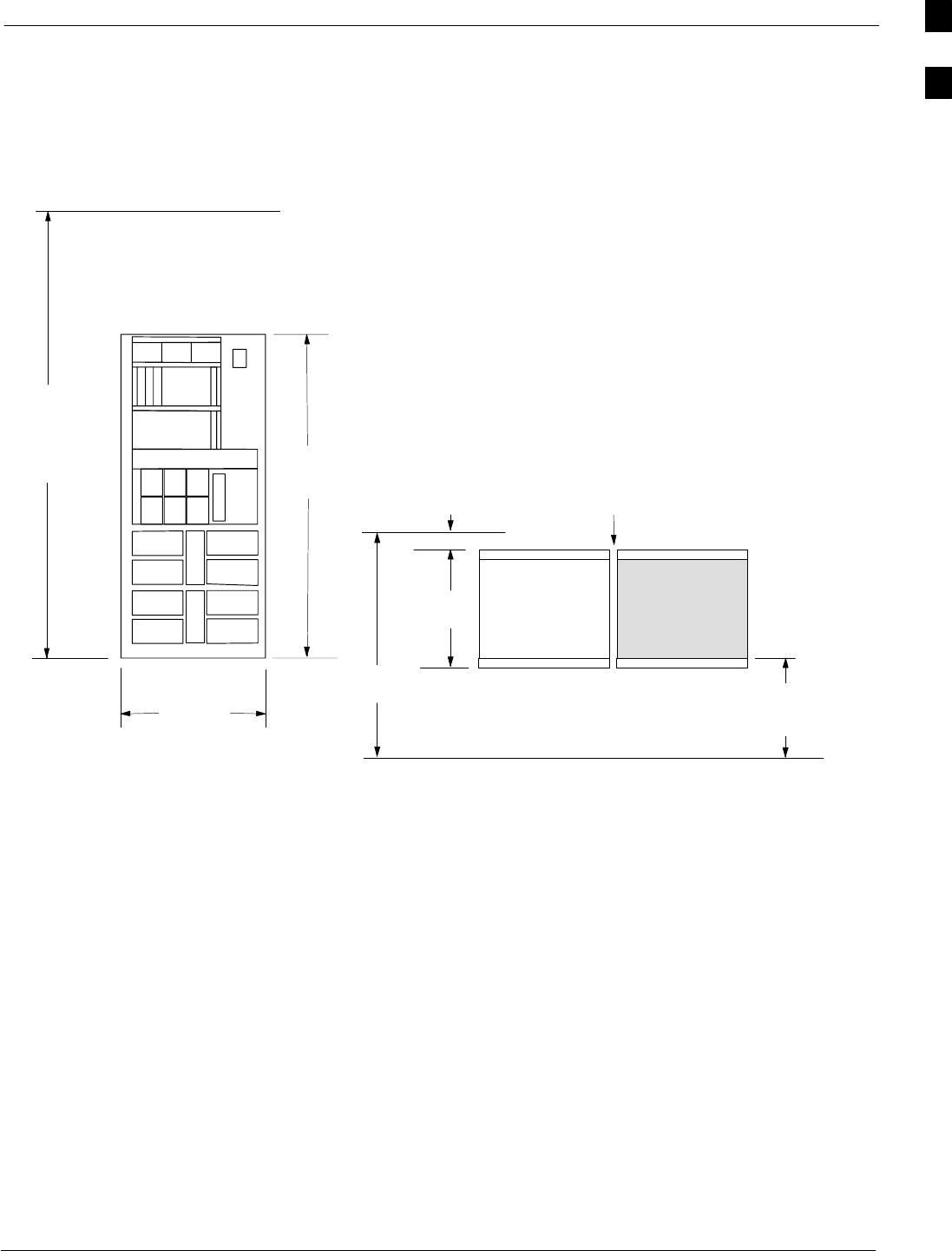
BTS Frame Site Layout
68P64115A19–4
Mar 2003 1X SC 4812T-MC BTS Hardware Installation - Software Release R2.16.1.x
CONTROLLED INTRODUCTION
1-7
BTS Frame Site Layout
Figure 1-1 provides an illustration of the dimensions and clearances for
the BTS.
Figure 1-1:Dimensions and Clearances for the BTS
FRONT VIEW
70.9 in.
(1800 mm)
for BTS
94.5 in.
(2400 mm)
(recommended
for lighting,
cable trays, etc.)
TOP VIEW
52.4 in.
(1330 mm)
5.9 in. (150 mm)
Rear Clearance
RECOMMENDED BTS CLEARANCES
0.12 in. (3 mm) spacing
between frames.
31.5 in.
(800 mm)
23.6 in. (600 mm)
minimum front clearance
for service access
FRONT
(Optional
2nd BTS)
24.2 in.
(615 mm)
ttti
ti–CDMA–WP–00043–02–ildoc–ftw
1
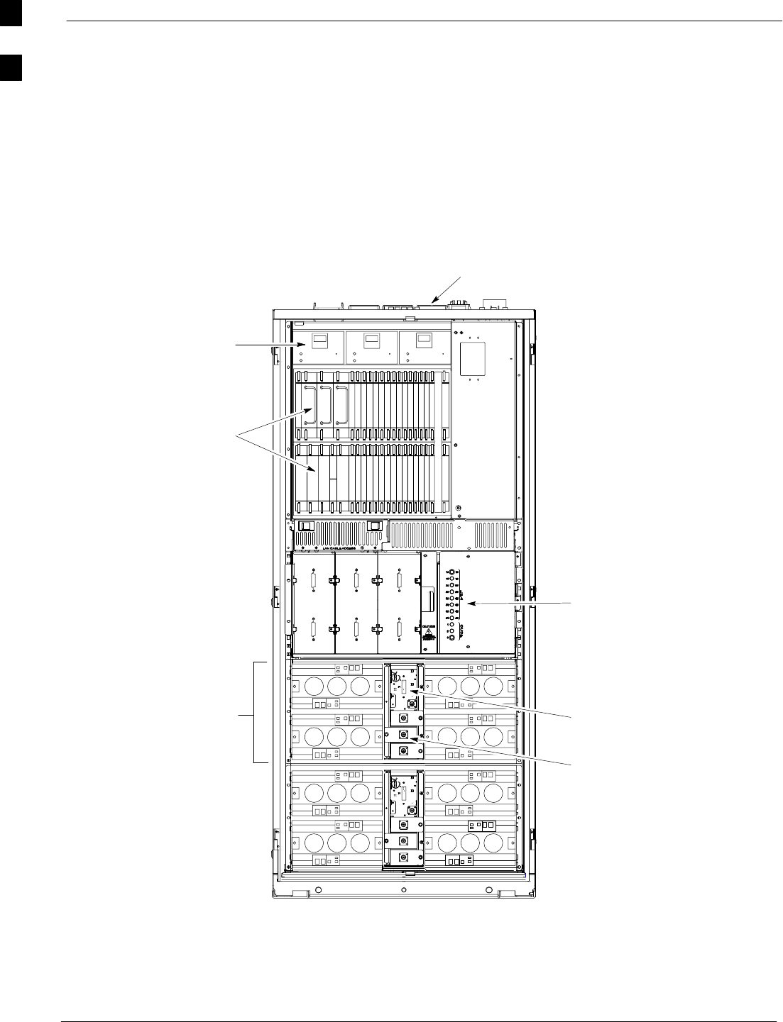
Base Transceiver Station (BTS) Frame Identification 68P64115A19–4
Mar 2003
1X SC 4812T-MC BTS Hardware Installation - Software Release R2.16.1.x
CONTROLLED INTRODUCTION
1-8
Base Transceiver Station (BTS) Frame Identification
BTS Frame
The Motorola SC 4812T–MC BTS (1800 mm) BTS frame contains RX
front-end and CLPAs housed in one frame. For increased channel
capacity, a second frame (called an “Expansion” frame) may be added to
the Starter Frame.
Figure 1-2: SC 4812T–MC BTS Frame
ti-CDMA-WP-00196-v01-ildoc-ftw
I/O Interconnect
C–CCP Cage
C–CCP Cage
and PA Breakers
Power
Fan Module
Enhanced
Trunking Module
TX Filter
Amplifier
Cage
Plate
1

Base Transceiver Station (BTS) Frame Identification
68P64115A19–4
Mar 2003 1X SC 4812T-MC BTS Hardware Installation - Software Release R2.16.1.x
CONTROLLED INTRODUCTION
1-9
I/O Plate
The I/O plate for the SC4812T–MC BTS Configuration (see Figure 2-1)
contains the following:
SAlarm connectors (2)
SSite I/O
SSpan I/O (2)
SRX antenna ports (1–12)
STX antenna ports (1–12)
SLocal Area Network (LAN) A and B Out
SLAN A and B In
SGround (GND) connection
SRF connector for expansion
SDC power inputs
SGlobal Positioning Satellite (GPS) connector
SLow Frequency Receiver/High Stability Oscillator (LFR/HSO)
SRemote GPS Distribution (RGD) card (required for expansion only)
SAir Exhaust Region
Site I/O
The Site I/O (see Figure 2-3) contains the following:
SAlarm Monitoring and Reporting connectors (AMR A & AMR B)
SRemote Global Positioning Satellite System (RGPS) connector
SMan Machine Interface (MMI) connector
Span I/O
The Span I/O (see Figure 2-3) contains the following:
STelco interface to network
SPOTS line interface to modem
Combined CDMA Channel Processor (C-CCP) Shelf
The C-CCP shelf (see Figure 1-2) contains the following:
SLow Frequency Receiver/High Stability Oscillator (LFR/HSO)
SClock Synchronization Manager (CSM) and CSM with GPS
SCDMA Clock Distribution (CCD) cards (2)
SPower Supply cards (2 minimum, 3 maximum)
SMulticoupler Preselector Cards (MPC) (2)
SAlarm Monitoring and Reporting (AMR) cards (2)
SMulti Channel CDMA (MCC8E/MCC24E or MCC–1X) cards
(up to 12)
SBroadband Transceiver (BBX2 or BBX–1X) cards (up to 13)
NOTE MC uses only BBX–1X or above. BBX2 or lower cards will not
satisfy the Multicarrier requirements.
1

Base Transceiver Station (BTS) Frame Identification 68P64115A19–4
Mar 2003
1X SC 4812T-MC BTS Hardware Installation - Software Release R2.16.1.x
CONTROLLED INTRODUCTION
1-10
SGroup Line Interface (GLI) cards (2)
SBBX Switch card
SCCP Fans (3)
SModem (optional)
Power Distribution Cage MC Configuration
The power distribution cage contains:
SBreaker Assembly
MC CLPA Cage
The MC CLPA cage contains:
SHigher Power Linear Power Amplifiers (CLPAs – 8 maximum per
cage; 16 maximum per frame)
SFan Modules (4 maximum per cage; 8 maximum per frame)
SPLC (2 maximum per cage; 4 maximum per frame)
SPLC Fillers Panel (2 maximum per cage; 4 maximum per frame)
– Only required in 1–Carrier, 3–Sector MC Operation
SMulticarrier Module (1 maximum per cage; 2 maximum per frame)
MC Module
The Multicarrier Module contains:
S Enhanced Trunking Module (1 maximum per module; 2 maximum
per frame)
S Transmit Filters (3 maximum per module; 6 maximum per frame)
In-Frame Components
The In-Frame components are:
SReceive Bandpass filters
External Components
The external components are:
SDirectional Couplers
SDuplexer Directional Couplers (DDCs)
SRadio Frequency Diagnostic Subsystem (RFDS)
1

Mar 2003 1X SC 4812T-MC BTS Hardware Installation - Software Release R2.16.1.x
CONTROLLED INTRODUCTION
2-1
Chapter 2
Inter-Frame Cabling
2

Inter-Frame Cabling 68P64115A19–4
Mar 2003
1X SC 4812T-MC BTS Hardware Installation - Software Release R2.16.1.x
CONTROLLED INTRODUCTION
2-2
Inter-Frame Cabling
Overview
This chapter provides the BTS inter-frame cabling procedures for the SC
4812T–MC BTS configuration.
NOTE Cabling is one of the most noticeable aspects of workmanship.
Straight runs and proper turns are critical for a positive
evaluation of the work. Power and signal cables should be run
with sharp corners, while grounds and antenna lines require
gentle corners.
Review the Material
Before installing cables, it is recommended that you become familiar
with the equipment and the cable connection locations. Start by
reviewing “Connection Locations” topic in this chapter and Table 2-1,
BTS Cable Descriptions and part numbers.
Configurations Supported
This chapter supports Inter-Frame cabling installation for a Standalone
Base Transceiver Station (BTS) in the following configurations:
S120 Degree Sector/Sector (3 Sector)
S60 Degree Sector/Sector (6 Sector)
Cabling Installation Order
To install BTS inter-frame cabling, perform the following procedures in
the order shown:
1. Alarm and Span Line
2. Modem/TELCO (optional)
3. GPS and optional LFR
4. Transmit path – perform one of the following based on site
specifications:
– 120 Degree Sector Transmit Path
– 60 Degree Sector Transmit Path
5. Receive path – Perform one of the following based on site
specifications:
– 120 Degree Sector Receive Path
– 60 Degree Sector Receive Path
6. Earth ground
7. DC power cables
Cable Labels
The “Overall Cabling Diagrams and Description” area provides
generalized cabling diagrams and cable descriptions. The labels used to
designate the cables in this area are used throughout this chapter.
2

Cable Connections
68P64115A19–4
Mar 2003 1X SC 4812T-MC BTS Hardware Installation - Software Release R2.16.1.x
CONTROLLED INTRODUCTION
2-3
Cable Connections
BTS Frame Description
The BTS is the interface between the span lines to/from the Centralized
Base Station Controller (CBSC) and the site antennas. This frame is
described in three sections:
SThe top interconnect plate where all connections are made.
SThe upper portion of the frame which houses circuit breakers, cooling
fans, and the C–CCP shelf.
SThe lower portion of the frame which houses the PA fans, PAs, and
TX filter.
Top I/O (Interconnect) Plate (Figure 2-1 and Figure 2-2)
All cabling to and from the BTS equipment frames is via the I/O
(interconnect) panel on the top of each frame. Connections made here
include:
SSpan lines
SRX antennas
STX antenna
SAlarm connections
SPower input
SLAN connections
SGPS input or Remote Global Positioning System (RGPS) on the Site
I/O Board
SRemote Global Positioning System Distribution (RGD)
SLORAN–C Low Frequency Receiver (LFR) input
SExpansion frame connection
SGround connections
2
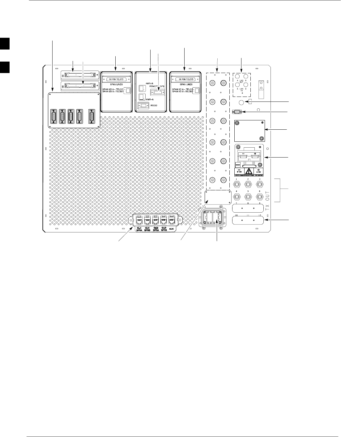
Cable Connections 68P64115A19–4
Mar 2003
1X SC 4812T-MC BTS Hardware Installation - Software Release R2.16.1.x
CONTROLLED INTRODUCTION
2-4
Figure 2-1: SC4812T–MC Starter Frame I/O Plate
FRONT
SPAN I/O
SITE I/O
ALARM
CONNECTORS
LAN
CONNECTIONS
RF GPS IN
3 TO 6 TRANSMIT
ANTENNA
CONNECTORS
DEPENDING ON
CONFIGURATION
HSO/LFR
FILLER PLATE
RECEIVE
ANTENNA
CONNECTORS
INPUT
CONNECTOR/
DC FILTER
ETHERNET ROUTER (IF USED;
OTHERWISE, FILLER PLATE) EXP IN FILLER
PLATE
3A
2A
1A
6A
5A
4A
3B
2B
1B
6B
5B
4B
REAR
2 TO 3
TRANSMIT
ANTENNA FILLER
PLATES
DEPENDING ON
CONFIGURATION
SPAN I/O A SITE I/O SPAN I/O B
ALARM B
SPAN I/O A
SPAN I/O B
ALARM A
SITE I/O
GND
DC FILTER 2
RX
RX
DC FILTER 1
SPAN I/O
REMOTE GPS DISTRIBUTION (RGD) MODULE –
USED ONLY IF EXPANSION FRAME(S) INSTALLED
RF EXPANSION PORT TO ANOTHER
BTS (USED ONLY IF EXPANSION FRAME
INSTALLED; OTHERWISE, FILLER PLATE
INSTALLED)
ti-CDMA-WP-00188-v01-ildoc-ftwREF
RGPS
2
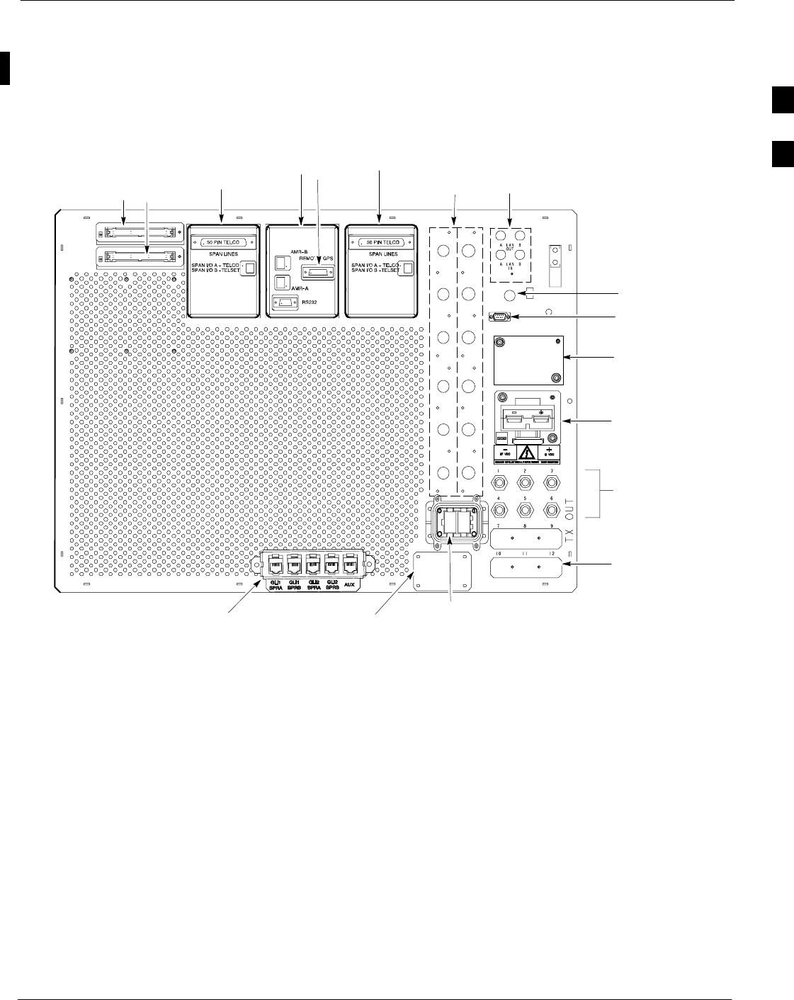
Cable Connections
68P64115A19–4
Mar 2003 1X SC 4812T-MC BTS Hardware Installation - Software Release R2.16.1.x
CONTROLLED INTRODUCTION
2-5
Expansion Frame I/O Plate
Figure 2-2 provides a detailed view of the connections associated with
the SC4812T–MC Expansion Frame I/O Plate.
Figure 2-2: SC4812T–MC Expansion Frame I/O Plate
FRONT
SPAN I/O
SITE I/O
ALARM
CONNECTORS
LAN
CONNECTIONS
RF GPS IN
3 TO 6 TRANSMIT
ANTENNA
CONNECTORS
DEPENDING ON
CONFIGURATION
HSO/LFR
FILLER PLATE
RECEIVE
ANTENNA
COVERS
INPUT
CONNECTOR/
DC FILTER
ETHERNET ROUTER (IF USED;
OTHERWISE, FILLER PLATE) EXP OUT
FILLER PLATE
3A
2A
1A
6A
5A
4A
3B
2B
1B
6B
5B
4B
REAR
2 TO 3
TRANSMIT
ANTENNA FILLER
PLATES
DEPENDING ON
CONFIGURATION
SPAN I/O A SITE I/O SPAN I/O B
ALARM B
SPAN I/O A
SPAN I/O B
ALARM A
SITE I/O
GND
DC FILTER 2
RX
RX
DC FILTER 1
SPAN I/O
RF EXPANSION PORT
FROM STARTER BTS
ti-CDMA-WP-00189-v01-ildoc-ftw–REF
RGPS
2
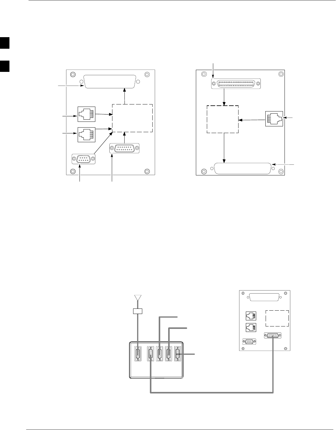
Cable Connections 68P64115A19–4
Mar 2003
1X SC 4812T-MC BTS Hardware Installation - Software Release R2.16.1.x
CONTROLLED INTRODUCTION
2-6
Site I/O and Span I/O Boards
Figure 2-3 provides a detailed view of the Site I/O and Span I/O boards.
Figure 2-3: Site I/O and Span I/O Boards
OVER VOLTAGE
PROTECTION
MMI
AMR A
AMR B
Site I/O
Span I/O
SURGE
PROTECTION
SPAN A TELCO
SPAN B TELSET
SPAN IN
REMOTE GPS IN
9–Pin D
8–Pin Jack
8–Pin Jack
50–Pin
D–sub
15–Pin D
50–Pin Telco
37–Pin
D–sub
6–Pin Jack
ti-CDMA-WP-00009-v01-ildoc-ftw
Remote GPS Distribution (RGD) Card
Figure 2-4 provides a detailed view of the Remote GPS Distribution
(RGD) card which is used with a Starter BTS to provide signal to the
Expansion frame.
Figure 2-4: RGD Board Cables Connection
NOTE:
RGD card is required on the Starter frame only.
It provides Remote GPS signal to the Expansion frame.
RGD
Expansion 1
Not Used
(Main out)
Remote GPS
Antenna
Not Used
Surge Protected
Punch block
Site I/O
ti-CDMA-WP-00010-v01-ildoc-ftwREF
2

Cabling Diagrams and Descriptions
68P64115A19–4
Mar 2003 1X SC 4812T-MC BTS Hardware Installation - Software Release R2.16.1.x
CONTROLLED INTRODUCTION
2-7
Cabling Diagrams and Descriptions
Cable Descriptions and Part Numbers
Table 2-1 lists the cable descriptions and part numbers. The letter listed
under the cable label column is used as a reference for ALL cabling
procedures and diagrams in this manual. This information also applies to
all system configurations.
Table 2-1: Cable Descriptions and Part Numbers
Cable Label Part Number Description
A CGDS1583461 Cable, 50-wire, shielded twisted 25 pair, 100 ohm, 24-AWG, 7.6 m
(25 ft), one male TELCO connector attached. One end of cable has
shielded twisted pairs, no connector.
CGDS1583462 Cable, 50-wire, shielded twisted 25 pair, 100 ohm, 24-AWG, 15.2 m
(50 ft), one male TELCO connector attached. One end of cable has
shielded twisted pairs, no connector.
B CGDS1583451 Cable, 60-wire, 100 ohm, 24-AWG, 7.6 m (25 ft), one 60-pin D
connector. One end of cable has shielded twisted pairs.
CGDS1583452 Cable, 60-wire, 100 ohm, 24-AWG, 15.2 m (50 ft), one 60-pin D
connector. One end of cable has shielded twisted pairs.
C CGDSMCXNJACK Cable, GPS antenna adapter, OSX connector and female N-type
connector. Mounts inside antenna assembly (assembly #
SGAN4000A)
E CGDS997264 Coaxial cable (RG-58), 50 ohm, shielded, 26 m (85.3 ft), 18 BNC
connectors included.
CGDS997265 Coaxial cable (RG-58), 50 ohm, shielded, 13 m (42.6 ft), 10 BNC
connectors included.
G CGDS2212602 15 ft. Jumper cable, N/M–N/M (only one end of the cable is
terminated with an N connector).
J CGDSGFEL04MS82 Cable, 4-wire, 26-AWG, 25 m (82 ft), two 4-pin RJ-11 connectors
attached to cable.
K N/A Cable, 50 ohm coaxial, two male N-type connectors. Maximum Loss:
< 4.5 dB at 1575 MHz for all cabling and connections between the
GPS antenna and the BTS frame.
Cable style and length is determined by the site configuration. Refer
to the site specific documentation for information about this cable.
The following are maximum suggested cable lengths for three
common cable types:
SRG-393U – with adapter cable and connectors; will accommodate
distances up to 12.5 m (41 ft).
SAndrew FT5-50T – Heliax with adapter cable and connectors; will
accommodate distances up to 39.6 m (130 ft).
SAndrew LDF7-50A – Heliax with adapter cable and connectors;
will accommodate distances up to 100.6 m (330 ft).
...continued on next page
2

Cabling Diagrams and Descriptions 68P64115A19–4
Mar 2003
1X SC 4812T-MC BTS Hardware Installation - Software Release R2.16.1.x
CONTROLLED INTRODUCTION
2-8
Table 2-1: Cable Descriptions and Part Numbers
Cable Label DescriptionPart Number
L CGDS315SA038 Cable, 5-wire, 100 ohm, 24-AWG, shielded twisted pair, 91.5 m
(300 ft). One 9-pin sub-miniature D-connector and one 5-pin circular
connector.
M N/A Power cable – See Power Cable section for detailed information on
cable termination lugs. Customer supplied cable.
N N/A Ground cable, 6-AWG, insulated copper wire, loop connectors.
Customer supplied cable.
2

Cabling Diagrams and Descriptions
68P64115A19–4
Mar 2003 1X SC 4812T-MC BTS Hardware Installation - Software Release R2.16.1.x
CONTROLLED INTRODUCTION
2-9
Overall Cabling Diagram (Single Frame)
Omni Systems
The following diagram shows the overall BTS cabling (power and
ground cables are not shown) for an Omni/Omni system. Table 2-1
contains the detailed cable descriptions.
3 and 6 Sector Systems
Figure 2-5 also represents the overall BTS cabling (power and ground
cables are not shown) for a 3 and 6 sector CDMA system. Refer to the
legend in the following diagram and Table 2-1 for detailed cable
descriptions.
Figure 2-5: Overall Signal Cabling Diagram for CDMA Systems
A/2 (SPAN LINES)
J/1 (MODEM/TELCO)
J/1 (TELSET)
NAME
NUMBER OF CABLES
CABLE LABEL
(OMNI) = OMNI/OMNI SYSTEMS
(SECTOR) = 60/120 DEGREE SECTOR/SECTOR SYSTEMS
B/2 (ALARMS)
TERMINATION
EQUIPMENT
LIGHTNING
ARRESTORS
G/6 (3 SECTORS)
G/12 (6 SECTORS)
RX ANTENNAS
LIGHTNING
ARRESTOR ANTENNA
K/1 (GPS)
(CDMA ONLY)
LIGHTNING
ARRESTOR
L/1 (LFR)
(CDMA ONLY)
Indicates equipment
existing prior to this
installation.
B/2 (ALARMS)
LEGEND
LIGHTNING
ARRESTOR
G/3 (3Sectors 1–4 CARRIER)
G/6 (6Sectors 1–2 CARRIER)
TX ANTENNAS
BTS
FRAME
PHONE
GPS
ANTENNA
LFR
ANTENNA
TX
ANTENNA
RX
REMOTE
GPS
LIGHTNING
ARRESTORS
ti-CDMA-WP-00045-v01-ildoc-ftw
2

Alarm / Span Cabling 68P64115A19–4
Mar 2003
1X SC 4812T-MC BTS Hardware Installation - Software Release R2.16.1.x
CONTROLLED INTRODUCTION
2-10
Alarm / Span Cabling
Objective
The objective of this procedure is to install the BTS alarm and span line
cabling.
Cable Labels
The cable designations are referenced to Table 2-1 in the “Overall
Cabling Diagrams and Description” area.
Equipment Needed
Table 2-2 lists the quantity and description of the required cables.
Table 2-2: Cables Needed for Alarm and Span Line Cabling
Cable Qty. Part Number Description
A1 or 2 CGDS1583461 Cable, 50-wire, shielded twisted 25 pair, 100 ohm, 24-AWG, 7.6 m
(25 ft), one male TELCO connector attached. One end of cable has
shielded twisted pairs, no connector.
CGDS1583462 Cable, 50-wire, shielded twisted 25 pair, 10 ohm, 24-AWG, 15.2 m
(50 ft), one male TELCO connector attached. One end of cable has
shielded twisted pairs, no connector.
B 2 CGDS1583451 Cable, 60-wire, 100 ohm, 24 AWG, 7.6 m (25 ft), one 60-pin
connector. One end of cable has shielded twisted pairs.
CGDS1583452 Cable, 60-wire, 100 ohm, 24 AWG, 15.2 m (50 ft), one 60-pin
connector. One end of cable has shielded twisted pairs.
2
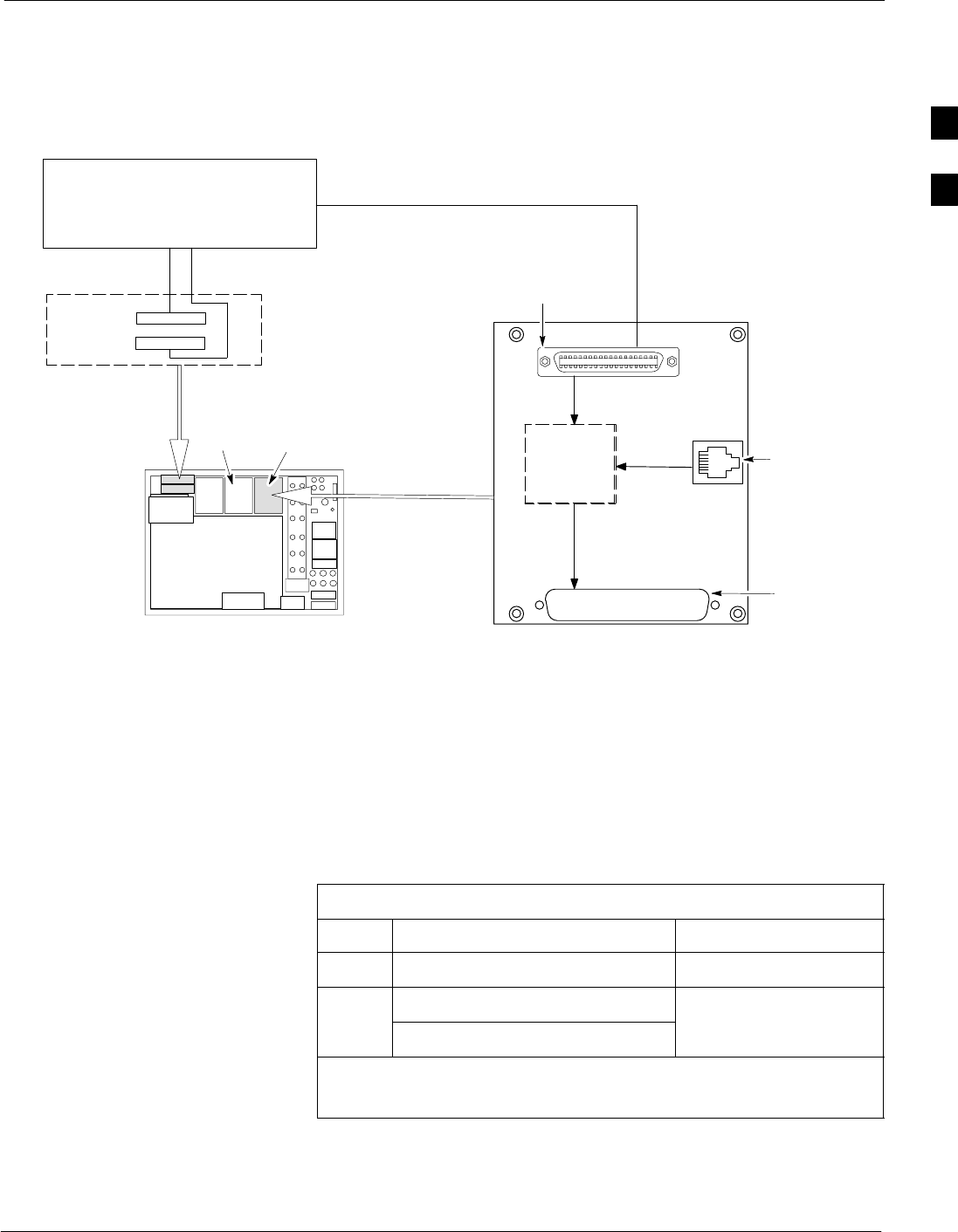
Alarm / Span Cabling
68P64115A19–4
Mar 2003 1X SC 4812T-MC BTS Hardware Installation - Software Release R2.16.1.x
CONTROLLED INTRODUCTION
2-11
Cabling Diagram
Figure 2-6 illustrates the recommended BTS span and alarm cabling.
Figure 2-6: Alarm and Span Line Cabling Details
TERMINATION
EQUIPMENT
BB
A
SC 4812T–MC
ALARM_B
ALARM_A
SPAN
I/O A SPAN
I/O B
Span I/O
SURGE
PROTECTION
SPAN A TELCO
SPAN B TELSET
SPAN IN
50–Pin Telco
37–Pin
D–sub
6–Pin Jack
ti-CDMA-WP-00046-v02 ildoc–ftw
Cable Run List
Table 2-3 provides the cable run list for alarm and span line cabling.
Table 2-3: Cable Run List for Alarm and Span Line Cabling
Cable From BTS Connector To
ASPAN LINE (on Span I/O board) Termination Equipment
BALARM A
Termination Equipment
ALARM B
T
erm
i
nat
i
on
E
qu
i
pment
* IMPORTANT
Site I/O and Span I/O boards are located on the top of the BTS frame.
2

Alarm / Span Cabling 68P64115A19–4
Mar 2003
1X SC 4812T-MC BTS Hardware Installation - Software Release R2.16.1.x
CONTROLLED INTRODUCTION
2-12
Install Span and Alarm Cables
Install the cables by using the cable run list provided in Table 2-3, by
referencing Figure 2-6, and by following the procedures in Table 2-4
through Table 2-6.
Span I/O Board (A) Installation
Perform the following procedure to connect cable A, to Span I/O board
A.
Table 2-4: Procedure to Install Span Line A Cable
Step Action
1Connect the TELCO connector of cable A to the SPAN LINE connector of Span I/O board A.
2Route the cable to the termination equipment.
3Cut the cable to length, and connect it to the termination equipment. Refer to Figure 2-7 and Table 2-8
for pin and signal information.
Span I/O Board (B) Installation
Perform the following procedure to connect cable A, to Span I/O board
B.
Table 2-5: Procedure to Install Span Line B Cable
Step Action
1Connect the TELCO connector of cable A to the SPAN LINE connector of Span I/O board B.
2Route the cable to the termination equipment.
3Cut the cable to length, and connect it to the termination equipment. Refer to Figure 2-7 and Table 2-8
for pin and signal information.
Alarm Cable Installation
Perform the following procedure to install the alarm cables.
Table 2-6: Procedure to Install Alarm Cables
Step Action
1Connect the 60-pin connector of one cable B to the ALARM A connector.
2Route the cable to the termination equipment.
3Cut the cable to length and connect it to the termination equipment. Refer to Figure 2-8, and Table 2-9
for pin and signal information. Alarm signal specifications are described on the following page.
4Repeat Steps 1 through 3, using the other cable B and the ALARM B connector.
2

Alarm / Span Cabling
68P64115A19–4
Mar 2003 1X SC 4812T-MC BTS Hardware Installation - Software Release R2.16.1.x
CONTROLLED INTRODUCTION
2-13
Alarm Signal Specifications
There are two ALARM connectors, A and B. A connector is always
functional; B is only functional when an AMR module is equipped in the
AMR 2 slot in the Combined CDMA Channel Processing Shelf
(C-CCP).
Function
ALARM connectors provide for Customer Defined Alarm Inputs and
Outputs. The customer can connect BTS site alarm input sensors and
output devices to the BTS, thus providing alarm reporting of active
sensors as well controlling output devices.
ALARM A connector provides 18 inputs and 8 outputs. ALARM B
connector provides 17 inputs and 8 outputs. If both AMR cards are
present, 35 inputs and 16 outputs are available.
Power Alarms Card (PAC)
The PAC combines alarms from five (5) power supply modules in the
BTS, generating one alarm output. The alarm signal is output through
the Alarm B connector, as follows:
SMajor alarm – pin 29
SMajor alarm return – pin 30
NOTE Alarm B pin connections above are for –48V frame application
only. These pins ar not used in the +27V application.
CAUTION These pins are NOT to be used as a customer defined input or
the PSM alarms will not function correctly.
Internal Connections
Both ALARM A and B connectors are cabled to the C-CCP shelf
backplane CUSTOMER I/O connector via a single 120-wire (twisted
pair) shielded cable. The inputs/outputs of ALARM A connector are
supported by the control interface module AMR 1. The input/outputs of
ALARM B connector are supported by the optional control interface
module AMR 2. The AMR detects signals from input sensors and
provides relay controlled switched contacts to output devices.
External Connections
Table 2-7 describes the characteristics and requirements for the inputs
(each of which consists of a wire/pin pair) and outputs (each of which
consists of 3-wires/pins–COM, NC, and NO).
2

Alarm / Span Cabling 68P64115A19–4
Mar 2003
1X SC 4812T-MC BTS Hardware Installation - Software Release R2.16.1.x
CONTROLLED INTRODUCTION
2-14
Table 2-7: External Alarm Connector Characteristics and Requirements
Inputs Outputs
To ensure proper operation, each pair to be used must be
connected to an external sensor that provides a dry-contact
closure. The customer sensor output contacts between an
optically isolated 9V DC signal and an isolated return.
S10k ohms or greater across the input pair is detected as an
open contact.
S1k ohms or less across the input pair is detected as a closed
contact.
Either of the above states can be defined by the customer in
system software as an alarm condition.
The customer output device control inputs
connect between the common (COM) and
either the normally closed (NC) or normally
open (NO) contacts of a relay.
SRelay contacts are load rated for a
maximum of 1 A @ 24 Vdc and 0.5 A @
48 Vdc.
The toggling of the relay contacts to the
opposite state is controlled by system
software.
2
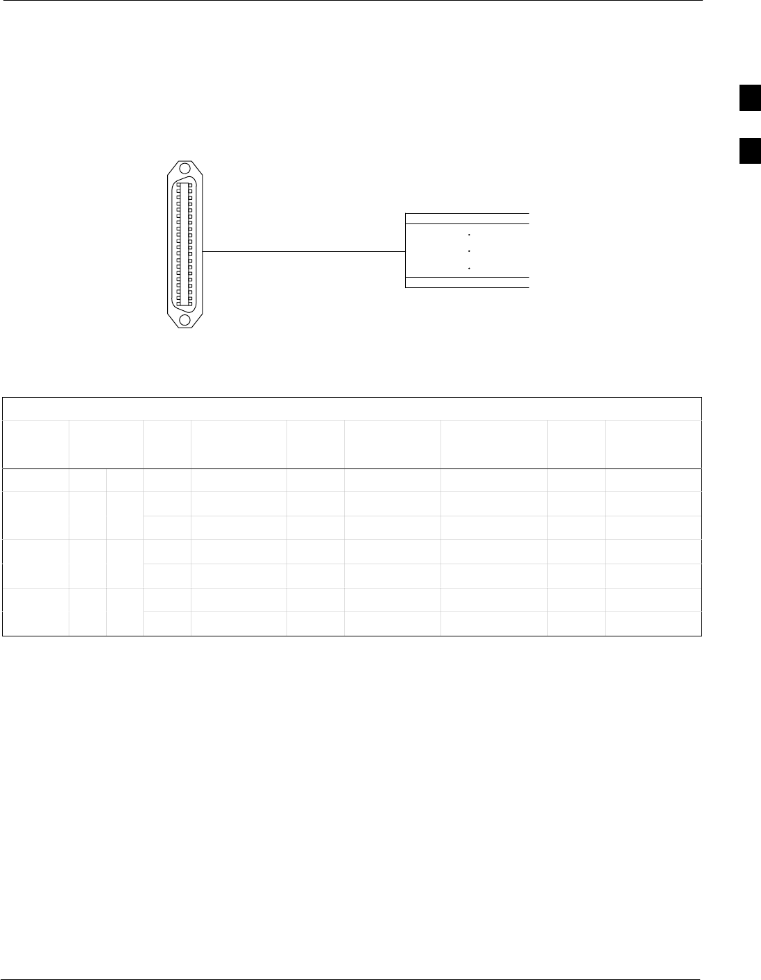
Alarm / Span Cabling
68P64115A19–4
Mar 2003 1X SC 4812T-MC BTS Hardware Installation - Software Release R2.16.1.x
CONTROLLED INTRODUCTION
2-15
Span Line Cable Pin Numbering
Figure 2-7 shows the pin numbering for Cable A – CGDS1583461,
CGDS1583462. Table 2-8 provides the Telco connector pin out
designators on the Span I/O PCB.
Figure 2-7: Cable A (Span Line) Pin Numbering
25
1
50 LOOSE WIRES, NO CONNECTOR
(MALE 50–PIN TELCO)
26
ti-CDMA-WP-00013-v01-ildoc-ftw
CABLES CGDS1583461 AND CGDS1583462
Table 2-8: Span I/O Connector
Span
I/O T1 Signal
Name Input
Pin
Wire Color Signal Name Input
Pin
Wire Color
A B
RX1 RX_TIP_1 1 BLU/WHT RX_RING_1 26 WHT/BLU
Span # 1 2 TX1 TX_TIP_1 2 ORG/WHT TX_RING_1 27 WHT/ORG
RX2 RX_TIP_2 3 GRN/WHT RX_RING_2 28 WHT/GRN
Span # 3 4 TX2 TX_TIP_2 4 BRN/WHT TX_RING_2 29 WHT/BRN
RX3 RX_TIP_3 5 SLT/WHT RX_RING_3 30 WHT/SLT
Span # 5 6 TX3 TX_TIP_3 6 BLU/RED TX_RING_3 31 RED/BLU
2
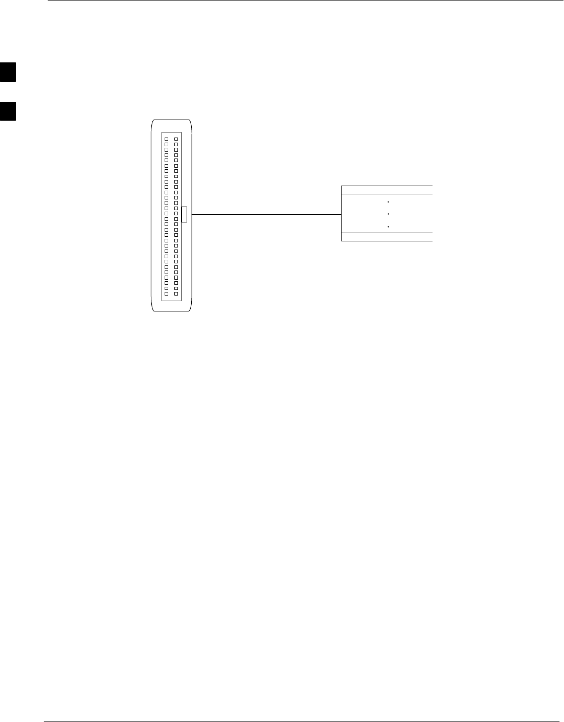
Alarm / Span Cabling 68P64115A19–4
Mar 2003
1X SC 4812T-MC BTS Hardware Installation - Software Release R2.16.1.x
CONTROLLED INTRODUCTION
2-16
Alarm Connectors Pin and Signal Information
Figure 2-8 shows the Alarm A and B pin numbering for Cable B -
CGDS1583451, CGDS1583452, respectively. Pin and signal information
are described in Table 2-9 for Alarm A and Table 2-10 for Alarm B.
Figure 2-8: Cable B (Alarm) Pin Numbering
59
1
60
2
5758
3
4
LOOSE WIRES, NO CONNECTOR
ti-CDMA-WP-00014-v01-ildoc-ftw
CABLES CGDS1583451 AND CGDS1583452
(FEMALE 60-PIN)
2

Alarm / Span Cabling
68P64115A19–4
Mar 2003 1X SC 4812T-MC BTS Hardware Installation - Software Release R2.16.1.x
CONTROLLED INTRODUCTION
2-17
Table 2-9: Pin and Signal Information for ALARM A Connectors
T
a
bl
e
2
-
9
:
Pi
n
an
d Si
gna
l I
n
f
orma
ti
on
f
or
ALARM A C
onnec
t
ors
Pin Wire Color Signal Name Pin Wire Color Signal Name
1 BLU/WHT A CDO1 NC 16 RED/GRN A CDO6 NC
2 WHT/BLU A CDO1 COM 17 BRN/RED A CDO6 COM
3 ORG/WHT A CDO1 NO 18 RED/BRN A CDO6 NO
4 WHT/ORG A CDO2 NC 19 SLT/RED A CDO7 NC
5 GRN/WHT A CDO2 COM 20 RED/SLT A CDO7 COM
6 WHT/GRN A CDO2 NO 21 BLU/BLK A CDO7 NO
7 BRN/WHT A CDO3 NC 22 BLK/BLU A CDO8 NC
8 WHT/BRN A CDO3 COM 23 ORG/BLK A CDO8 COM
9 SLT/WHT A CDO3 NO 24 BLK/ORG A CDO8 NO
10 WHT/SLT A CDO4 NC 25 GRN/BLK Cust Retn 1
11 BLU/RED A CDO4 COM 26 BLK/GRN A CDI 1
12 RED/BLU A CDO4 NO 27 BRN/BLK Cust Retn 2
13 ORG/RED A CDO5 NC 28 BLK/BRN A CDI 2
14 RED/ORG A CDO5 COM 29 SLT/BLK Cust Retn 3
15 GRN/RED A CDO5 NO 30 BLK/SLT A CDI 3
Pin Wire Color Signal Name Pin Wire Color Signal Name
31 BLU/YEL CUST RTRN 4 46 VIO/GRN A CDI 11
32 YEL/BLU A CDI 4 47 BRN/VIO CUST RTRM 12
33 ORG/YEL CUST RTRN 5 48 VIO/BRN A CDI 12
34 YEL/ORG A CDI 5 49 SLT/VIO CUST RTRM 13
35 GRN/YEL CUST RTRN 6 50 VIO/SLT A CDI 13
36 YEL/GRN A CDI 6 51 RED/WHT CUST RTRM 14
37 BRN/YEL CUST RTRN 7 52 WHT/RED A CDI 14
38 YEL/BRN A CDI 7 53 BLK/WHT CUST RTRM 15
39 SLT/YEL CUST RTRN 8 54 WHT/BLK A CDI 15
40 YEL/SLT A CDI 8 55 YEL/WHT CUST RTRM 16
41 BLU/VIO CUST RTRN 9 56 WHT/YEL A CDI 16
42 VIO/BLU A CDI 9 57 VIO/WHT CUST RTRM 17
43 ORG/VIO CUST RTRN 10 58 WHT/VIO A CDI 17
44 VIO/ORG A CDI 10 59 BLK/RED CUST RTRM 18
45 GRN/VIO CUST RTRN 11 60 RED/BLK A CDI 18
NC – normally closed, NO – normally open, Com – common, CDO – Customer Defined Output,
CDI – Customer Defined Input
All Cust Rtrm 1–18 are electronically tied together at the RFMF.
The A CDI numbering is from the LMF/OMCR/CBSC perspective. LMF/OMCR/CBSC starts the numbering at 1 (giving
1 – 18). Actual cable hardware starts the numbering at 0 (giving 0–17)
2

Alarm / Span Cabling 68P64115A19–4
Mar 2003
1X SC 4812T-MC BTS Hardware Installation - Software Release R2.16.1.x
CONTROLLED INTRODUCTION
2-18
Table 2-10: Pin and Signal Information for ALARM B Connectors
Pin Wire Color Signal Name Pin Wire Color Signal Name
1 BLU/WHT B CDO9 NC 16 RED/GRN B CDO14 NC
2 WHT/BLU B CDO9 COM 17 BRN/RED B CDO14 COM
3 ORG/WHT B CDO9 NO 18 RED/BRN B CDO14 NO
4 WHT/ORG B CDO10 NC 19 SLT/RED B CDO15 NC
5 GRN/WHT B CDO10 COM 20 RED/SLT B CDO15 COM
6 WHT/GRN B CDO10 NO 21 BLU/BLK B CDO15 NO
7 BRN/WHT B CDO11 NC 22 BLK/BLU B CDO16 NC
8 WHT/BRN B CDO11 COM 23 ORG/BLK B CDO16 COM
9 SLT/WHT B CDO11 NO 24 BLK/ORG B CDO16 NO
10 WHT/SLT B CDO12 NC 25 GRN/BLK B CDI 19
11 BLU/RED B CDO12 COM 26 BLK/GRN Cust Retn 19
12 RED/BLU B CDO12 NO 27 BRN/BLK B CDI 20
13 ORG/RED B CDO13 NC 28 BLK/BRN Cust Retn 20
14 RED/ORG B CDO13 COM 29 Power Supply Module Alarm*
15 GRN/RED B CDO13 NO 30 Power Supply Module Alarm Return*
Pin Wire Color Signal Name Pin Wire Color Signal Name
31 BLU/YEL B CDI 22 46 VIO/GRN CUST RTRM 29
32 YEL/BLU CUST RTRN 22 47 BRN/VIO B CDI 30
33 ORG/YEL B CDI 23 48 VIO/BRN CUST RTRM 30
34 YEL/ORG CUST RTRN 23 49 SLT/VIO B CDI 31
35 GRN/YEL B CDI 24 50 VIO/SLT CUST RTRM 31
36 YEL/GRN CUST RTRN 24 51 RED/WHT B CDI 32
37 BRN/YEL B CDI 25 52 WHT/RED CUST RTRM 32
38 YEL/BRN CUST RTRN 25 53 BLK/WHT B CDI 33
39 SLT/YEL B CDI 26 54 WHT/BLK CUST RTRM 33
40 YEL/SLT CUST RTRN 26 55 YEL/WHT B CDI 34
41 BLU/VIO B CDI 27 56 WHT/YEL CUST RTRM 34
42 VIO/BLU CUST RTRN 27 57 VIO/WHT B CDI 35
43 ORG/VIO B CDI 28 58 WHT/VIO CUST RTRM 35
44 VIO/ORG CUST RTRN 28 59 BLK/RED B CDI 36
45 GRN/VIO B CDI 29 60 RED/BLK CUST RTRM 36
NC – normally closed, NO – normally open, Com – common, CDO – Customer Defined Output,
CDI – Customer Defined Input
All Cust Rtrm 19–36 are electronically tied together at the RFMF.
The A CDI numbering is from the LMF/OMCR/CBSC perspective. LMF/OMCR/CBSC starts the numbering at 19 (giving
19 – 36). Actual cable hardware starts the numbering at 0 (giving 0–17)
*CAUTION
Reserved for PSM Alarm signal (–48V application ONLY). DO NOT use these pins for CDOs or CDIs.
2

Equipment Compliance
68P64115A19–4
Mar 2003 1X SC 4812T-MC BTS Hardware Installation - Software Release R2.16.1.x
CONTROLLED INTRODUCTION
2-19
Equipment Compliance
This equipment complies with Part 68 of the Federal communications
commission (FCC) Rules and regulations. On the top of the Frame is a
label, located inside the cabinet frame on the top, left side, that contains,
among other information, the FCC Registration Number and Ringing
Equivalence Number (REN) for this equipment. If requested, this
information must be provided to the telephone company.
The REN is useful to determine the quantity of the devices which may
connect to the telephone line. Excessive REN’s on the telephone line
may result in the devices not ringing in response to incoming call. In
most, but not all areas, the sum of the REN’s should not exceed five
(5.0). To be certain of the number of devices that may be connected to
the line as determined by the total REN’s, contact the telephone
company to determine the maximum REN for the calling area.
If the dial-in site access modem causes harm to the telephone network,
the telephone company will notify you in advance that temporary
discontinuance of service may be required. If advance notice is not
practical, the telephone company will notify you of the discontinuance as
soon as possible. Also, you will be advised of your right to file a
complaint with the FCC if you believe it is necessary.
The telephone company may make changes in its facilities, equipment,
operations, or procedures that could affect the operation of your dial-in
site access modem. If this happens, the telephone company will provide
advance notice so that you can modify your equipment as required to
maintain uninterrupted service.
If you experience trouble with the dial-in site access modem, contact
Motorola Service Center for repair and/or warranty information:
Motorola Cellular Service Center (MCSC)
1501 W. Shure Drive
Arlington Heights, Illinois 60004
Phone Number: (847) 632–5390
If the trouble is causing harm to the telephone network, the telephone
company may request you to disconnect the equipment from the network
until the problem is solved. You should not attempt to repair this
equipment yourself. This equipment contains no customer or
user-serviceable parts.
Changes or modifications not expressly approved by Motorola could
void your authority to operate this equipment.
2

BTS System Timing Options 68P64115A19–4
Mar 2003
1X SC 4812T-MC BTS Hardware Installation - Software Release R2.16.1.x
CONTROLLED INTRODUCTION
2-20
BTS System Timing Options
Timing Sources
The BTS is able to receive timing information from the following
sources:
SRF Global Positioning Satellite (RF GPS)
SRemote GPS (RGPS)
SLow Frequency Receiver (LFR)
SHigh Stability Oscillator (HSO)
Customers have the option of installing either an RF GPS or Remote
GPS. Site characteristics determine the cabling to be installed (GPS,
LFR or HSO, if any).
Timing sources can be used independently. However, in typical
applications, sites are outfitted in pairs so that if a failure occurs in the
main source, a backup system will provide timing to keep the cell site in
operation.
Typical installations include:
SRF GPS with LFR backup
SRemote GPS with LFR backup
SGPS with LFR or HSO backup
Each of these cabling installations are described in the following
sections.
2
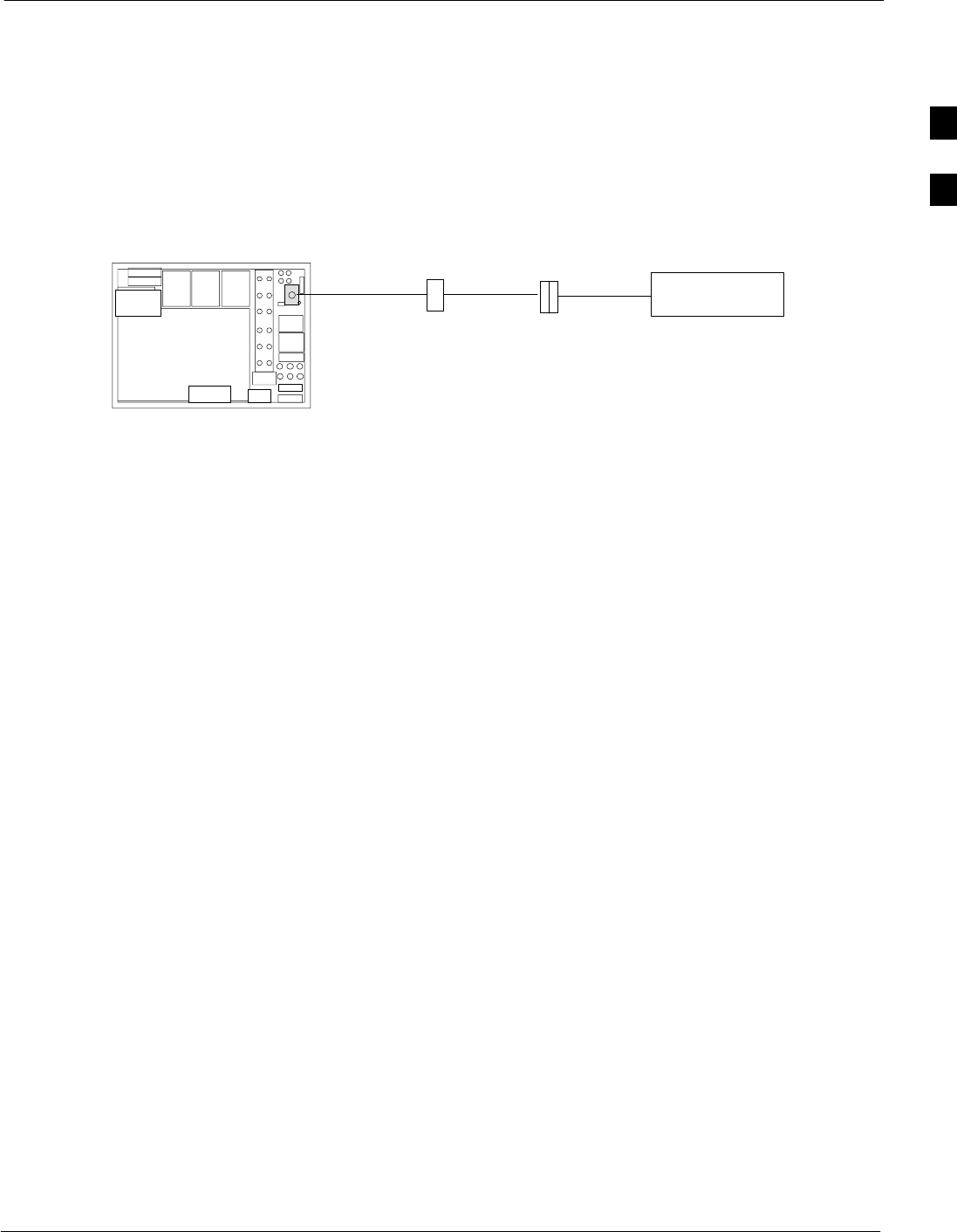
RF Global Positioning Satellite (RF GPS) Cabling
68P64115A19–4
Mar 2003 1X SC 4812T-MC BTS Hardware Installation - Software Release R2.16.1.x
CONTROLLED INTRODUCTION
2-21
RF Global Positioning Satellite (RF GPS) Cabling
RF GPS Cabling Diagram
Figure 2-9 shows a detailed diagram of RF GPS cabling in the Starter
frame. Refer to Table 2-1 for a description of the cables required for
installing the RF GPS.
Figure 2-9: RF GPS Cabling Detail
RF GPS
ANTENNA
KC
Cable C is mounted
inside the antenna
assembly.
Starter BTS
NOTE: Surge protection for the GPS
antenna must pass 5 Vdc.
Surge Protector
K
2
RF Global Positioning Satellite (RF GPS) Cabling 68P64115A19–4
Mar 2003
1X SC 4812T-MC BTS Hardware Installation - Software Release R2.16.1.x
CONTROLLED INTRODUCTION
2-22
Cable Run List
Table 2-11 lists the cable runs for the BTS GPS and LFR cables. If
lightning arrestors are used with the LFR antenna, refer to the site
specific documentation for cabling information.
Table 2-11: Cable Run List for GPS and LFR Cabling
Cable From Connector To
K GPS GPS Antenna
RF GPS Cabling Installation Procedure
Install each cable by referring to the cable run list in Table 2-1, the
cabling diagram in Figure 2-9, and the procedure in Table 2-12. If
lightning arrestors are used with the RF GPS antenna, refer to the site
specific documentation for cabling information.
NOTE Site specific characteristics determine the GPS/LFR cabling that
is installed.
Table 2-12: Procedure to Install the RF GPS Cabling
Step Action
1Follow the OEM information to disassemble the GPS antenna and gain access to the OSX connector.
2Connect the the OSX connector of cable C to the antenna.
3Follow the OEM information to assemble the GPS antenna with cable C attached.
4Connect one end of cable K to the N-type connector of cable C.
5Connect the other end of cable K to the GPS connector on the BTS.
2
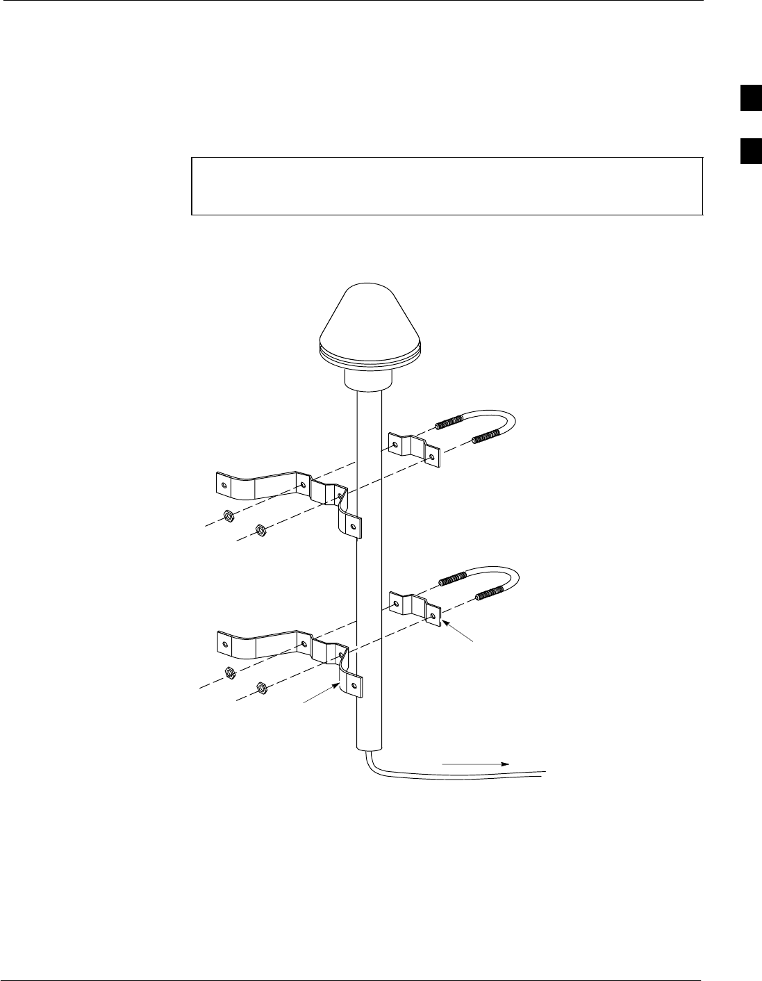
Remote Global Positioning Satellite (RGPS) Cabling
68P64115A19–4
Mar 2003 1X SC 4812T-MC BTS Hardware Installation - Software Release R2.16.1.x
CONTROLLED INTRODUCTION
2-23
Remote Global Positioning Satellite (RGPS) Cabling
RGPS Cabling Diagrams
Figure 2-10 depicts the detail for mounting the RGPS antenna and the
cable leading to the BTS. Figure 2-11 shows the detailed remote GPS
cabling diagram.
NOTE The Remote GPS cable is comprised of 6-twisted pairs of wires.
For proper Remote GPS operation, each black wire in this cable
is unique and MUST be paired with its proper mate.
Figure 2-10: Remote GPS Mounting Detail
CABLE TO BTS
WALL MOUNTING
BRACKETS (2)
CLAMP
BRACKETS (2)
ti-CDMA-WP-00016-v01-ildoc-ftw
2
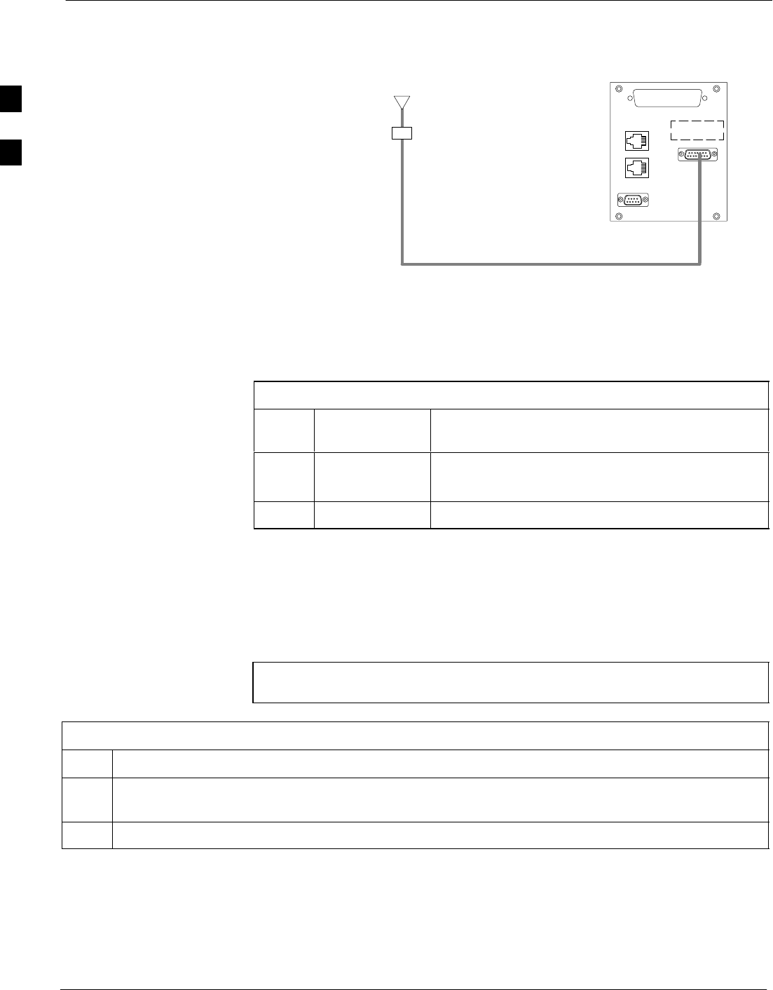
Remote Global Positioning Satellite (RGPS) Cabling 68P64115A19–4
Mar 2003
1X SC 4812T-MC BTS Hardware Installation - Software Release R2.16.1.x
CONTROLLED INTRODUCTION
2-24
Figure 2-11: Remote GPS Cabling Diagram
MMI
AMR A
Remote GPS
Antenna
Surge
Protected
Punchblock
(Customer
supplied)
A1
A2
Cabling Run List
Table 2-13 provides a listing of the cables need for installing the Remote
GPS option.
Table 2-13: Remote GPS Cable Descriptions and Part Numbers
Cable
Label Part Number Description
A1T472Ax RGD Antenna to Punchblock Cable; x=A–F for
different A1 cable length 50 feet to 2000 feet
A23086433H07 Punchblock to Site I/O board
Install RGPS Cable
Install each cable by referring to the cable run list in Table 2-13, the
cabling diagram in Figure 2-11, and the procedure in Table 2-14. If
lightning arrestors are used with the RGPS, refer to the site specific
documentation for cabling information.
NOTE Site specific characteristics determine the GPS/LFR cabling that
is installed.
Table 2-14: Installing the RGPS Cabling
Step Action
1Connect cables A1 and A2 into the punch block, as if they were part of the same cable, cut in the
middle maintaining color code and signal integrity..
2Connect the same corresponding color on both sides of the punchblock (see Figure 2-11).
2
Low Frequency Receiver / High Stability Oscillator (LFR/HSO) Cabling
68P64115A19–4
Mar 2003 1X SC 4812T-MC BTS Hardware Installation - Software Release R2.16.1.x
CONTROLLED INTRODUCTION
2-25
Low Frequency Receiver / High Stability Oscillator (LFR/HSO)
Cabling
Overview
This section provides the information to install the Low Frequency
Receiver/High Stability Oscillator (LFR/HSO) cabling for CDMA
systems.
Cable Labels
The cable designations are referenced in Table 2-1 on 2-7 in the “Overall
Cabling Diagrams and Description” area.
Cable Run List
Table 2-15 lists the cable runs for the BTS GPS and LFR cables. If
lightning arrestors are used with the LFR antenna, refer to the site
specific documentation for cabling information.
Table 2-15: Cable Run List for GPS and LFR Cabling
Cable From Connector To
L LFR LFR Antenna
Procedure
Install each cable by referring to the cable run list in Table 2-15, the
cabling diagram in Figure 2-9, and the procedure in Table 2-16. If
lightning arrestors are used with the LFR antenna, refer to the site
specific documentation for cabling information.
NOTE Site specific characteristics determine the GPS/LFR cabling that
is installed.
Table 2-16: Procedure to Install LFR Cabling
Step Action
1Attach the 9-pin subminiature connector of cable L to the LFR connector of the BTS.
2Attach the 5-pin circular connector of cable L to the LFR antenna.
2

Low Frequency Receiver / High Stability Oscillator (LFR/HSO) Cabling 68P64115A19–4
Mar 2003
1X SC 4812T-MC BTS Hardware Installation - Software Release R2.16.1.x
CONTROLLED INTRODUCTION
2-26
LFR Cable (Cable L) Pin/Signal Information
The pin/signal information for the LFR cable is presented in Table 2-17.
This information applies to the standard LFR cable.
Table 2-17: Pin /Signal Information for LFR Cable (Cable C)
Pin Number for Connector Type
9-Pin D Connector 5-Pin Circular
(for antenna/preamplifier) Wire Color Description
1 D Red Antenna +
(power and signal)
6 E Black
(paired with red) Antenna –
(power and signal)
5 A White Calibrator +
9 B Black
(paired with white) Calibrator –
3 C Bare Drain from shield
2
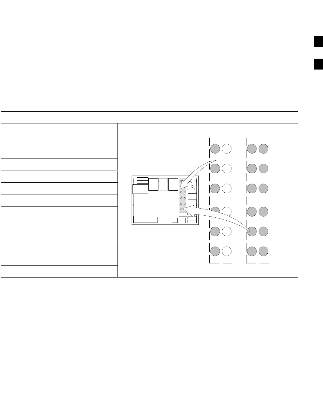
BTS Antenna Configuration
68P64115A19–4
Mar 2003 1X SC 4812T-MC BTS Hardware Installation - Software Release R2.16.1.x
CONTROLLED INTRODUCTION
2-27
BTS Antenna Configuration
Overview
This section provides detail on the antenna configurations supported by
the BTS, including:
S3 Sector
S6 Sector
RX Antenna Configurations
Table 2-18 provides the RX antenna configurations for the BTS.
Table 2-18: RX Antenna Configuration
Configuration 3 Sector 6 Sector RX Antenna Connections
1A S1 Main S1 Main
RX Antenna Connections
1B S1 Div S1 Div
1A 4A
1A 4A
2A S2 Main S2 Main
1A 4A
1A 4A
2B S2 Div S2 Div 2A 5A
2A 5A
3A S3 Main S3 Main
3B S3 Div S3 Div RX
3A 6A
RX
3A 6A
4A S4 Main
RXRX
4B S4 Div 1B 4B
1B 4B
I/O Plate
5A S5 Main 2B 5B
2B 5B
I/O Pl
a
t
e
5B S5 Div
2B 5B
2B 5B
6A S6 Main 3B 6B
3B 6B
6B S6 Div 3 Sector 6 Sector
2
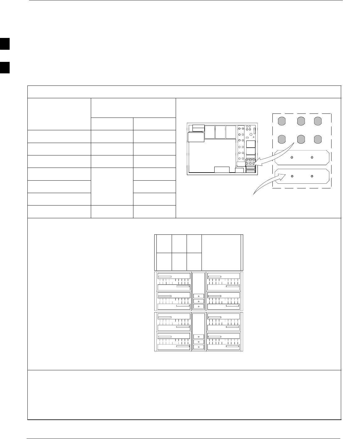
BTS Antenna Configuration 68P64115A19–4
Mar 2003
1X SC 4812T-MC BTS Hardware Installation - Software Release R2.16.1.x
CONTROLLED INTRODUCTION
2-28
TX Antenna Configurations
Table 2-19, show configurations for a fully populated SC 4812T–MC
frame with 4X4 ETM. For a SC 4812T–MC frame populated with a 3X3
ETM the lower right quadrant will not be populated.
Table 2-19, also displays the I/O plate for 3 to 6 Transmit Antenna
Connectors (depending on configuration) and 2 to 3 Transmit Antenna
Filler plates (depending on configuration).
Table 2-19: Multicarrier BTS TX Antenna Configuration
TX Filter
Sector/Carrier
I/O Plate
BTS TX Ports 3 Sector 6 Sector I
/O
Plate 123
TX
TX 1 S1/C1–C4 S1/C1–C2
456
TX
TX 2 S2/C1–C4 S2/C1–C2
4
56
TX 3 S3/C1–C4 S3/C1–C2 789
TX 4 S4/C1–C2
TX 5 S5/C1–C2
TX 6 S6/C1–C2 FILLER PLATE
Max No. Carriers 4 2
ti-C
D
1C
2C
3C
4C
1D
2D
3D
4D
3A
2A
1A 1B
2B
3B
4B
C1 (C1)
C2 (C2)
C3 (C1)
C4 (C2)
C1 (C1)
C2 (C2)
C3 (C1)
C4 (C2)
C1 (C1)
C2 (C2)
C3 (C1)
C4 (C2)
C1 (C1)
C2 (C2)
C3 (C1)
C4 (C2)
4A
S4
MCM
1
SC4812T–MC
Carrier
Numbering Carrier
Numbering
3 Sector and 6 Sector
3 Sector
(6 Sector)
3 Sector
(6 Sector)
S5
S6
S1
S2
S3
MCM
2
CLPACLPA
CLPA
CLPA
CLPA
CLPA
CLPA
CLPA
CLPA
CLPA
CLPA
CLPA
CLPA
CLPA
CLPA
CLPA
NOTES:
1. C1, C2, C3 and C4 denote carriers 1, 2, 3 and 4, respectively.
2. The maximum number of CLPAs for a given carrier is shown.
3. SC 4812T–MC frames with a 3 X 3 ETM, the lower right quadrant will not be populated.
4. SC 4812T–MC frame with a 3 Sector configuration only one MCM is used.
2
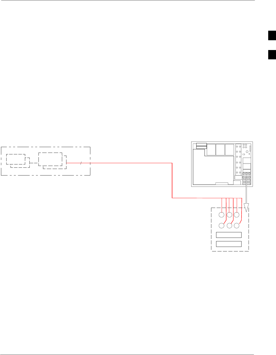
BTS 60 Degree Sector (6 Sector) Transmit Path Cabling
68P64115A19–4
Mar 2003 1X SC 4812T-MC BTS Hardware Installation - Software Release R2.16.1.x
CONTROLLED INTRODUCTION
2-29
BTS 60 Degree Sector (6 Sector) Transmit Path Cabling
Objective
The objective of this procedure is to install the BTS transmit path
cabling.
Cable Labels
The cable designations referenced in Table 2-20, provide the quantities
and descriptions of the cables required for the procedure.
Cabling Diagram
Figure 2-12 and Figure 2-13 shows direct connect cable configurations
(both inside and outside the BTS frame). Table 2-21 describes the
antenna cable connection ports.
Figure 2-12: 60 Degree Sector (6 Sector) Transmit Path Cabling Details (Outside Frame)
TX OUT
LIGHTNING
ARRESTOR
ANTENNA CARRIER 1 & 2
G (See Table 2-20) I/O PLATE
6
1..6
1..
6
ti-CDMA-WP-00048-v04-ildoc-ftw–REF
123
456
789
10 11 12
DIRECT CONNECT
2
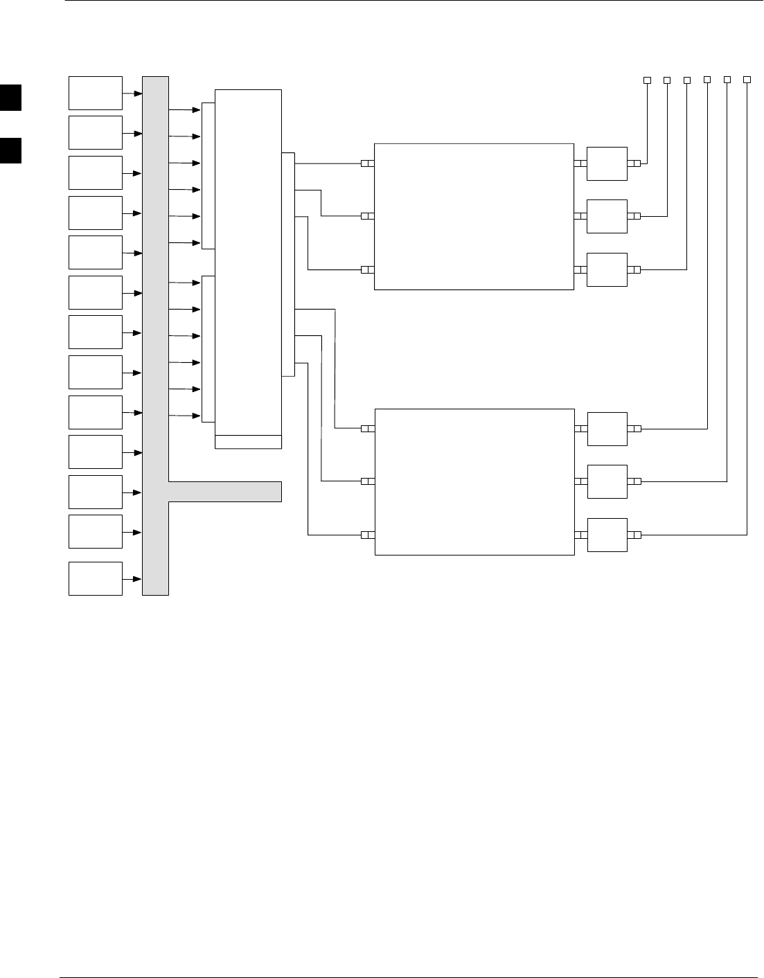
BTS 60 Degree Sector (6 Sector) Transmit Path Cabling 68P64115A19–4
Mar 2003
1X SC 4812T-MC BTS Hardware Installation - Software Release R2.16.1.x
CONTROLLED INTRODUCTION
2-30
Figure 2-13: 60 Degree Sector (6 Sector) Transmit Path Cabling Details (Inside frame)
BBX–1
S1 C1 TX1
6–Sector
MCPA CIO
BBX–2
S2 C1
BBX–3
S3 C1
BBX–4
S1 C3
BBX–5
S2 C3
BBX–6
S3 C3
BBX–7
S1 C2
BBX–8
S2 C2
BBX–9
S3 C2
BBX–10
S1 C4
BBX–11
S2 C4
BBX–12
S3 C4
BBX–R
TX2
TX3
TX4
TX5
TX6
TX7
TX8
TX9
TX10
TX11
TX12
J1
J5
TX4 TX5 TX6
N–F N–F N–F
BPF
BPF
MULTITONE
MODULE
BPF
SMB
SMB
SMB
C–CCP BACKPLANE
ti-CDMA-WP-00243-v01-ildoc-ftw
J14
MULTITONE
MODULE
SMB
SMB
SMB
TX1 TX2 TX3
N–F N–F N–F
PA1PA2PA3PA4PA5PA6 HARTING 6–PACK
BPF
BPF
BPF S1
C1 & C2
S2
C1 & C2
S3
C1 & C2
S4
C1 & C2
S5
C1 & C2
S6
C1 & C2
S1
C1 & C2
S2
C1 & C2
S3
C1 & C2
S4
C1 & C2
S5
C1 & C2
S6
C1 & C2
HARTING 6–PACK
J7
HARTING 6–PACKHARTING 6–PACK
2

BTS 60 Degree Sector (6 Sector) Transmit Path Cabling
68P64115A19–4
Mar 2003 1X SC 4812T-MC BTS Hardware Installation - Software Release R2.16.1.x
CONTROLLED INTRODUCTION
2-31
60 Degree Sector Configuration
Table 2-20 provides the Cable Run List for 60 degree sector transmit
paths.
Table 2-20: Cable Run List for 60 Degree Sector TX Configuration
Cable Cable Parts Connecting Lightning Arrestors To BTS TX Connectors
G Direct
Quantity 6
TX Ports for 6 Sector Configuration
Table 2-21: Cable Run List for 60 Degree Sector Receive Path Cabling
Cable Cable path connecting Lightning Arrestors to BTS TX connectors TX Ports Used
Quantity 6TX 1A–6A
Procedure Install each cable by using the cable run list in Table 2-20, the cabling
diagram in Figure 2-12, and the procedure in Table 2-22. Each cable is
installed the same way.
Table 2-22: Installing the 60 Degree Sector TX Path Cables
Step Action
1Attach the connector–equipped end of the cables to the BTS TX connectors.
2Route the cables to the lightning arrestors.
3Cut the cables to length and label them accordingly. Install connectors on the cables and attach the
cables to the Lightning Arrestors.
2
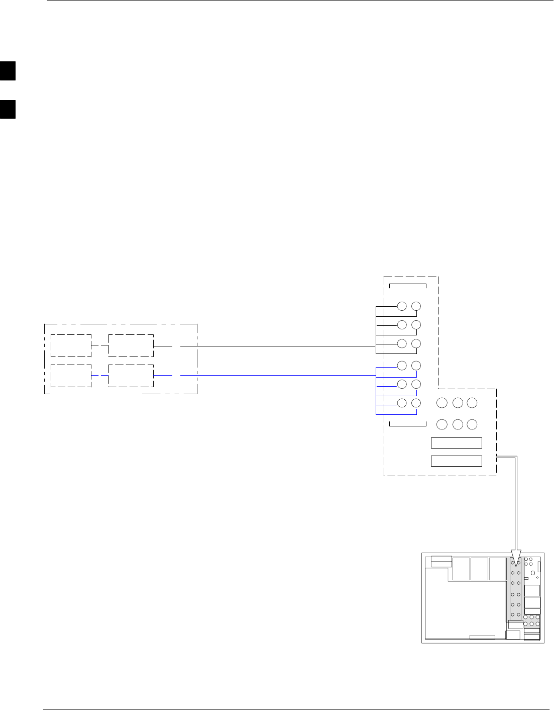
BTS 60 Degree Sector (6 Sector) Receive Path Cabling 68P64115A19–4
Mar 2003
1X SC 4812T-MC BTS Hardware Installation - Software Release R2.16.1.x
CONTROLLED INTRODUCTION
2-32
BTS 60 Degree Sector (6 Sector) Receive Path Cabling
Objective
The objective of this procedure is to install the BTS transmit path
cabling.
Cable Labels
The cable designations are referenced in Table 2-1 the “Overall Cabling
Diagrams and Description” area. Table 2-23, and Table 2-24 provide the
quantities and descriptions of the cables required for this procedure.
Cabling Diagram
Figure 2-14 shows RX (Main/Diversity) antenna configurations.
Table 2-24 describes the antenna cable connection ports.
Figure 2-14: 60 Degree Sector (6 Sector) Receive Path Cabling Details
DIRECT CONNECTION
LIGHTNING
ARRESTORS
LIGHTNING
ARRESTORS
1A, 2A, 3A, 4A, 5A, 6A
1B, 2B, 3B, 4B, 5B, 6B
1A, 2A, 3A
4A, 5A, 6A
MAIN
DIV
1B, 2B, 3B
4B, 5B, 6B
ti-CDMA-WP-00049-v04-ildoc-ftw–REF
3A
2A
6A
5A
4A
3B
2B
1B
6B
5B
4B
1A
123
456
789
10 11 12
RX
RX
I/O PLATE
G
GMAIN
DIVERSITY
2

BTS 60 Degree Sector (6 Sector) Receive Path Cabling
68P64115A19–4
Mar 2003 1X SC 4812T-MC BTS Hardware Installation - Software Release R2.16.1.x
CONTROLLED INTRODUCTION
2-33
Table 2-23: Cables Needed for 120 Degree Sector Receive Path
Cable Qty. Part Number Description
G 12 CGDS2212602 15 ft. Jumper Cable, N/M–N/M.
Table 2-24: Cable Run List for 60 Degree Sector Receive Path Cabling
Cable Cable path connecting Lightning Arrestors
to BTS RX connectors RX CONNECT RX Ports Used
Quantity
6 MAIN RX 1A–6A
Q
uant
i
ty 6 DIVERSITY RX 1B–6B
Procedure
Install each cable by using the cable run list in Table 2-23, the cabling
diagram in Figure 2-14, and the procedure in Table 2-25. Each cable is
installed the same way.
Table 2-25: Installing the 60 Degree Sector Receive Path Cables
Step Action
1Attach the connector–equipped end of the cables to the BTS RX connectors.
2Route the cables to the lightning arrestors.
3Cut the cables to length and label them accordingly. Install connectors on the cables.
2
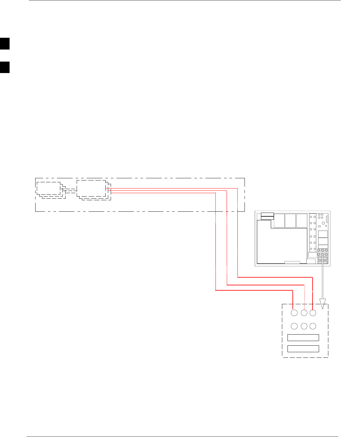
BTS 120 Degree Sector (3 Sector) Transmit Path Cabling 68P64115A19–4
Mar 2003
1X SC 4812T-MC BTS Hardware Installation - Software Release R2.16.1.x
CONTROLLED INTRODUCTION
2-34
BTS 120 Degree Sector (3 Sector) Transmit Path Cabling
Objective
The objective of this procedure is to install the 120 degree BTS transmit
path cabling.
Cable Labels
The cable designations are referenced to Table 2-1 in the “Cabling
Diagrams and Description” area. Table 2-26 and Table 2-27 provide the
quantities and descriptions of the cables required for this procedure.
Cabling Diagram
Figure 2-15 and Figure 2-16 shows both inside and outside cable
connections for 3 Sector direct connect configurations. Table 2-26 and
Table 2-27, describes the antenna cable connection ports.
Figure 2-15: 120 Degree Sector (3 Sector) Transmit Path Cabling Details (outside the frame)
LIGHTNING
ARRESTOR
ANTENNA
G
DIRECT CONNECTION
ti-CDMA-WP-00050-v04-ildoc-ftw
TX OUT
123
456
789
10 11 12
I/O PLATE
S1 C1–C4
S2 C1–C4
S3 C1–C4
2
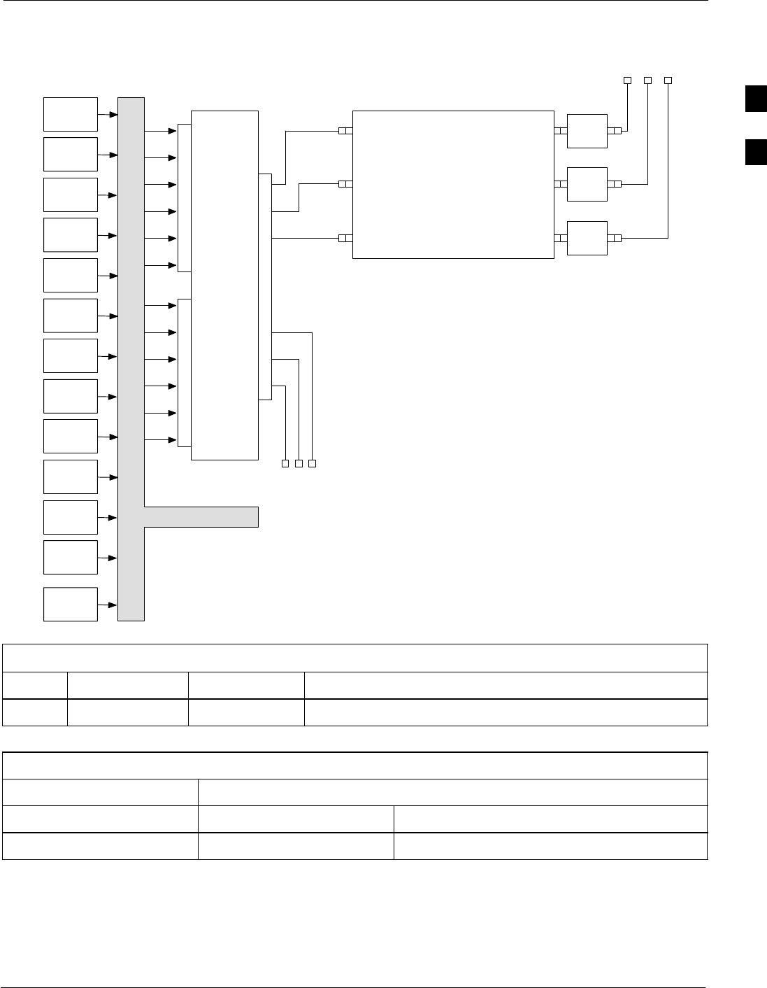
BTS 120 Degree Sector (3 Sector) Transmit Path Cabling
68P64115A19–4
Mar 2003 1X SC 4812T-MC BTS Hardware Installation - Software Release R2.16.1.x
CONTROLLED INTRODUCTION
2-35
Figure 2-16: 120 Degree Sector (3 Sector) Transmit Path Cabling Details (inside the frame)
BPF
BPF
BBX–1
S1 C1 TX1
3–Sector
MCPA CIO
BBX–2
S2 C1
BBX–3
S3 C1
BBX–4
S1 C3
BBX–5
S2 C3
BBX–6
S3 C3
BBX–7
S1 C2
BBX–8
S2 C2
BBX–9
S3 C2
BBX–10
S1 C4
BBX–11
S2 C4
BBX–12
S3 C4
BBX–R
TX2
TX3
TX4
TX5
TX6
TX7
TX8
TX9
TX10
TX11
TX12
J1
J5
J14 MULTITONE
MODULE
BPF S1
C1–C4
S2
C1–C4
S3
C1–C4
NOT USED
S1
C1–C4
S2
C1–C4
S3
C1–C4
SMB
SMB
SMB
TX1 TX2 TX3
N–F N–F N–F
C–CCP BACKPLANE
SMB
ti-CDMA-WP-00242-v01-ildoc-ftw
PA1PA2PA3PA4PA5PA6 HARTING 6–PACK
Table 2-26: Cables Needed for 120 Degree Sector Transmit Path
Cable Qty. Part Number Description
G(see Table 2-27) CGDS2212602 15 ft Jumper Cable, N/M–N/M.
Table 2-27: Cable Run List for 120 Degree Sector TX Configuration
Cable Cable Parts Connecting Lightning Arrestors To BTS TX Connectors
G Direct BTS TX Ports
Quantity (TX–only path) 3TX1, TX2, TX3
2

BTS 120 Degree Sector (3 Sector) Transmit Path Cabling 68P64115A19–4
Mar 2003
1X SC 4812T-MC BTS Hardware Installation - Software Release R2.16.1.x
CONTROLLED INTRODUCTION
2-36
Procedure Install each cable by using the cable run list in Table 2-27, the cabling
diagram in Figure 2-15, and the procedure in Table 2-28. Each cable is
installed the same way.
Table 2-28: Installing the 120 Degree Sector TX Path Cables
Step Action
1Attach the connector–equipped end of the cables to the BTS TX connectors.
2Route the cables to the lightning arrestors.
3Cut the cables to length and label them accordingly. Install connectors on the cables and attach the
cables to the Lightning Arrestors.
2

BTS 120 Degree Sector (3 Sector) Receive Path Cabling
68P64115A19–4
Mar 2003 1X SC 4812T-MC BTS Hardware Installation - Software Release R2.16.1.x
CONTROLLED INTRODUCTION
2-37
BTS 120 Degree Sector (3 Sector) Receive Path Cabling
Objective
The objective of this procedure is to install the BTS RX Port receive
path cabling. 120-degree sector receive path cabling is used for CDMA
systems.
Cable Labels
The cable designations are referenced to Table 2-1 in the “Cabling
Diagrams and Description” area. Table 2-29 and Table 2-30 provide the
quantities and descriptions of the cables required for this procedure.
Table 2-29: Cables Needed for 120 Degree Sector Receive Path
Cable Qty. Part Number Description
G(see Table 2-30) CGDS2212602 15 ft. Jumper Cable, N/M–N/M.
Cabling Diagram
Figure 2-17 shows RX antenna (Direct Connect) configuration.
Table 2-30 describes the antenna cable connection ports.
Table 2-30: Cable Run List for 120 Degree Sector Receive Path Cabling
Cable Cable path connecting Lightning Arrestors
to BTS RX connectors RX Antenna Ports
Quantity
6
RX 1A
RX 2A
RX 3A
Q
uant
i
ty
6
RX 1B
RX 2B
RX 3B
2
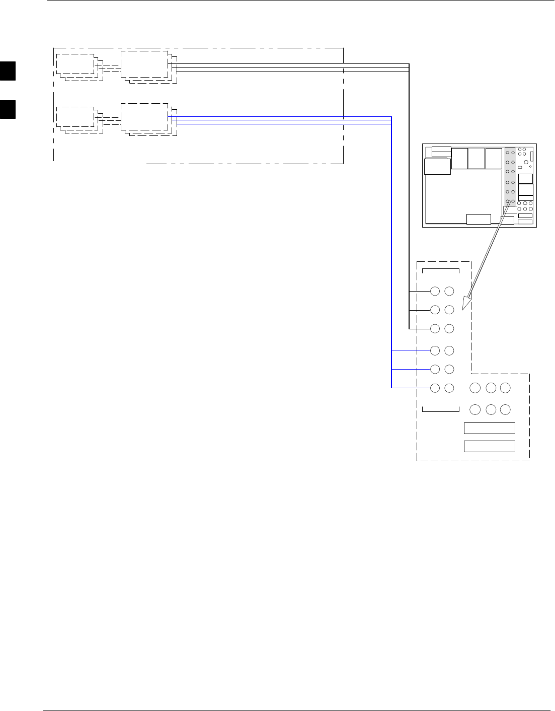
BTS 120 Degree Sector (3 Sector) Receive Path Cabling 68P64115A19–4
Mar 2003
1X SC 4812T-MC BTS Hardware Installation - Software Release R2.16.1.x
CONTROLLED INTRODUCTION
2-38
Figure 2-17: 120 Degree Sector (3 Sector) Receive Path Cabling Details
LIGHTNING
ARRESTOR
ANTENNA
LIGHTNING
ARRESTOR
ANTENNA
G
G
DIRECT CONNECTION
ti-CDMA-WP-00185-v01-ildoc-ftw
3A
2A
6A
5A
4A
3B
2B
1B
6B
5B
4B
TX OUT
1A
123
456
789
10 11 12
RX
RX
MAIN / A / 1A
MAIN / B / 2A
MAIN / G / 3A
DIV / A / 1B
DIV / B / 2B
DIV / G / 3B
MAIN
DIVERSITY
2

BTS 120 Degree Sector (3 Sector) Receive Path Cabling
68P64115A19–4
Mar 2003 1X SC 4812T-MC BTS Hardware Installation - Software Release R2.16.1.x
CONTROLLED INTRODUCTION
2-39
Cabling Procedure
Install each cable by referring to the cable run list in Table 2-30, the
cabling diagram in Figure 2-17, and the procedure in Table 2-31. Each
cable is installed the same way.
Table 2-31: Installing the 120 Degree Sector Receive Path Cables
Step Action
1Attach the connector-equipped end of the cables to the BTS RX connectors.
2Route the cables to the lightning arrestors.
3Cut the cables to length and label them accordingly. Install connectors on the cables, and attach the
cables to the lightning arrestors.
2
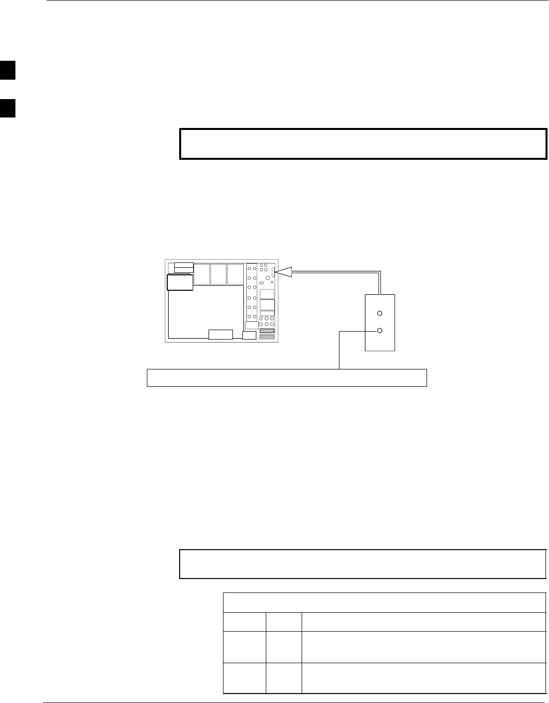
Earth Ground Cabling 68P64115A19–4
Mar 2003
1X SC 4812T-MC BTS Hardware Installation - Software Release R2.16.1.x
CONTROLLED INTRODUCTION
2-40
Earth Ground Cabling
Objective
The objective of this procedure is to install the BTS earth ground cables.
This manual describes only general procedures for grounding the site.
Refer to the Grounding Guidelines for Cellular Radio Installations,
Motorola part no. 68P81150E62, for detailed grounding information.
WARNING Each cabinet must be grounded separately and NOT daisy
chained together!
Earth Grounding Diagram
Figure 2-18 illustrates the earth ground cable.
Figure 2-18: Earth Ground Cabling Details
MASTER GROUND BAR
N
GND
ti-CDMA-WP-00052-v02–ildoc–ftw
BTS
Cable Labels
The cable designations are referenced in Table 2-1, in the “Cabling
Diagrams and Description” section of this manual.
Equipment Needed
Table 2-32 describes the cable and ring lugs required for earth
grounding.
NOTE Two-hole (Thomas & Betts part no. 54207; or equivalent) are
recommended.
Table 2-32: Items Required for Earth Grounding
Item Qty Description
Cable
(N) 1Ground cable, 6-AWG, insulated copper wire, loop
connectors. Customer supplied cable.
Ring
Lugs 1Ring lugs to attach to the BTS end of the cable.
Customer supplied item.
2

Earth Ground Cabling
68P64115A19–4
Mar 2003 1X SC 4812T-MC BTS Hardware Installation - Software Release R2.16.1.x
CONTROLLED INTRODUCTION
2-41
Install Earth Grounding Cables
Install the earth ground cables according to the procedures in Table 2-33
(see Figure 2-18).
WARNING SDo NOT wear a wrist strap when servicing the power
supplies or power distribution cabling! Serious personal
injury can result.
SBefore starting the procedure, ensure that the BTS power
cables are not connected to the main DC source.
Table 2-33: Procedure to Install Earth Grounding Cables
Step Action
1Route the ground cables (cable N) between the Master
Ground Bar (MGB) and the BTS frames.
NOTE
Ground cables must not have sharp bends.
2Strip insulation from the BTS end of each cable.
3Attach a ring lug to the BTS end of each cable.
4Connect a ground cable (cable N) to the ground stud of each
BTS frame.
5Connect the ground lugs to directional coupler bracket,
duplexer bracket, and RFDS (if used).
6Attach the ground cables to the MGB using the appropriate
connectors.
2

BTS Power Cabling 68P64115A19–4
Mar 2003
1X SC 4812T-MC BTS Hardware Installation - Software Release R2.16.1.x
CONTROLLED INTRODUCTION
2-42
BTS Power Cabling
Objective
The objective of this procedure is to define the BTS’s site power
distribution system requirements, and install the DC power input
cabling.
Important Guidelines
Several guidelines must be followed in the design of the site power
distribution system. Depending on site requirements and specific
guidelines, two different cabling choices are offered in this section,
Option A or Option B. Read this entire section before power cabling the
BTS.
Inrush Current
When the frame is powered on, there is the potential for an inrush
current which exceeds the steady state current draw of the frame. In
order to prevent this inrush current from affecting other equipment,
power feeds and circuit breakers should NOT be shared between the
BTS and any other equipment. This BTS is designed to comply with the
ETS 300-132-2 standard for DC inrush current.
Feeds and Breaker Sizes
Table 2-34 lists different site configurations, depending on the number of
carriers. Select a power distribution system configuration that is most
appropriate for your site. Figure 2-19 identifies the BTS Breaker Panel.
Table 2-34: DC Filter Power Feed Configurations
Number of
Carriers
Number of
Feeds Required
(+ and – pair) Breaker Size
(per Feed) Utilize
Cable Option
1–2 1 125A A
3–4 1 250A A
3–4 2 125A B
2
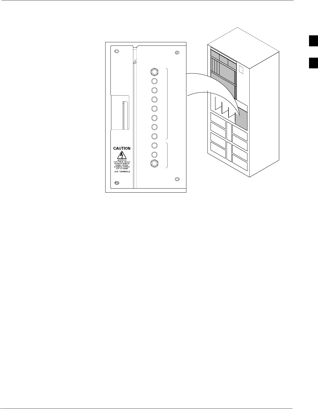
BTS Power Cabling
68P64115A19–4
Mar 2003 1X SC 4812T-MC BTS Hardware Installation - Software Release R2.16.1.x
CONTROLLED INTRODUCTION
2-43
Figure 2-19: Breaker Panel Identification
ti-CDMA-WP-00227-v01-ildoc-ftw–REF
L
P
A
C
C
C
P
2A
4A
2B
4B
2C
4C
2D
4D
1A
3A
1B
3B
1C
3C
1D
3D
50
1
2
3
50 50 50 50 50 50 50 50 50 50
Source Impedance
The frame power interface supports AWG 2/0, AWG 3/0, and AWG 4/0
cable sizes.
In order to limit the voltage drop due to cable resistance, the length of
the cable runs from power source to BTS must be less than the
maximum distance for each cable size shown in the Table 2-35. These
values apply for both single feed and two feed configurations.
2
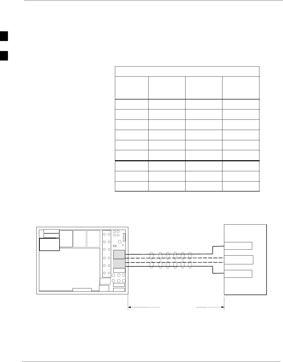
BTS Power Cabling 68P64115A19–4
Mar 2003
1X SC 4812T-MC BTS Hardware Installation - Software Release R2.16.1.x
CONTROLLED INTRODUCTION
2-44
In the + 27 V configuration the power supply input “+” and “–”
terminals are isolated from the BTS chassis ground. In order to control
the inductance at the BTS power input due to the feed cables, the
positive and negative cables (feed and return) must be bound together at
intervals of 1 meter or less (see Figure 2-20).
Meeting these limits will ensure a voltage drop of less than 2% due to
cable resistance, and will control the source impedance to ensure
stability of the power supply.
Table 2-35: Maximum Cable Length
Number of
Carriers Number of
Feeds Cable Type
Maximum
Length in
meters
1–2 1 AWG 2/0 22
1–2 1 AWG 3/0 28*
1–2 1 AWG 4/0 28*
3–4 1 AWG 2/0 12.2
3–4 1 AWG 3/0 15.4
3–4 1 AWG 4/0 19.4
3–4 2 AWG 2/0 22
3–4 2 AWG 3/0 28
3–4 2 AWG 4/0 28*
* Limited by inductance rather than voltage drop.
Figure 2-20: Length and Tie-Down Requirements for BTS Power Cables
ti-CDMA-WP-00077-v02–ildoc–ftw REF.
1
2
POWER SOURCE
BREAKER 1
TIE ALL CABLES
AT 1 METER INTERVALS
See Table 2-35
for cable length
BREAKER 2
GROUND
BTS
2
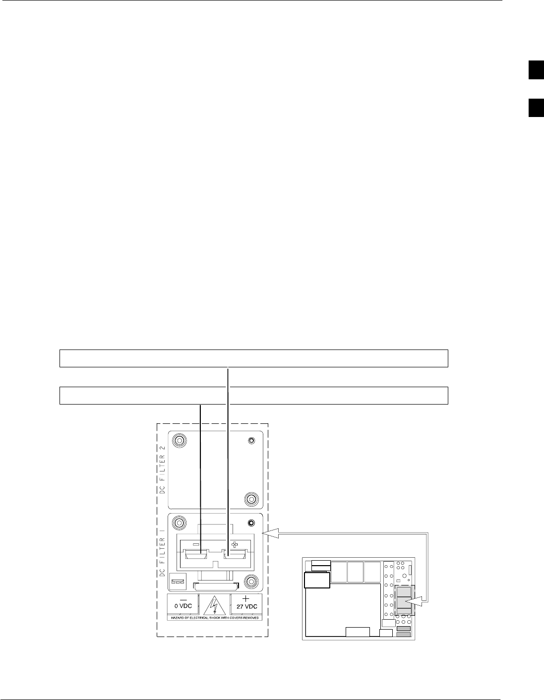
BTS Power Cabling
68P64115A19–4
Mar 2003 1X SC 4812T-MC BTS Hardware Installation - Software Release R2.16.1.x
CONTROLLED INTRODUCTION
2-45
Current Sharing
For installations with one power feed (2 carrier system cabling) use
Option A (see Figure 2-21).
For installations with two feeds (e.g., 3 carrier or 4 carrier systems using
cabling Option B, (see Figure 2-22), the total current will be shared
between the two feeds. If the current becomes greatly unbalanced
between the two feeds, the circuit breaker carrying the greater current
may be tripped. In this case, all current will flow in the remaining feed,
causing the breaker to be tripped, and the BTS to go out-of-service. In
order to minimize the current imbalance between the feeds, it is
necessary to:
Sensure the cable lengths and sizes of the cables are the same,
Sthe breakers on the two feeds are the same (same manufacturer, same
part number, etc.), and
Scontacts and connectors are identical.
For short cable runs with two feeds, it is recommended that 2/0 cable be
used rather than 3/0 or 4/0.
Option A. Power Distribution Cabling for +27 V BTS Configuration with One
Power Feed
Figure 2-21: BTS Power Cabling for the +27 V BTS Configuration using One Power Feed
+27 VOLTS
GROUND (0 VOLTS)
M/1
M/1
SC4812T–MC
ti-CDMA-WP-00190-v01-ildoc-ftw–REF
2
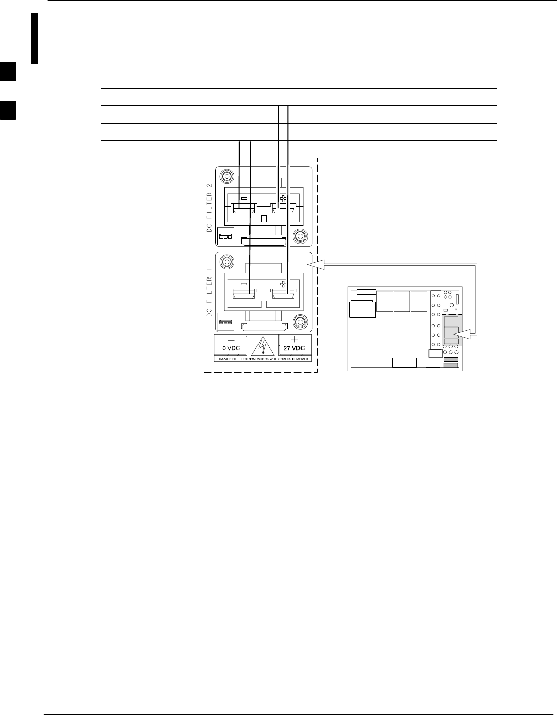
BTS Power Cabling 68P64115A19–4
Mar 2003
1X SC 4812T-MC BTS Hardware Installation - Software Release R2.16.1.x
CONTROLLED INTRODUCTION
2-46
Option B. Power Distribution Cabling for +27 V BTS Configuration with Two
Power Feeds
Figure 2-22: BTS Power Cabling for the + 27 V BTS Configuration using TwoPower Feeds
+ 27 VOLT
GROUND (0 VOLT)
M/2
ti-CDMA-WP-00193-v01-ildoc-ftw–REF
SC4812T–MC
M/2
2
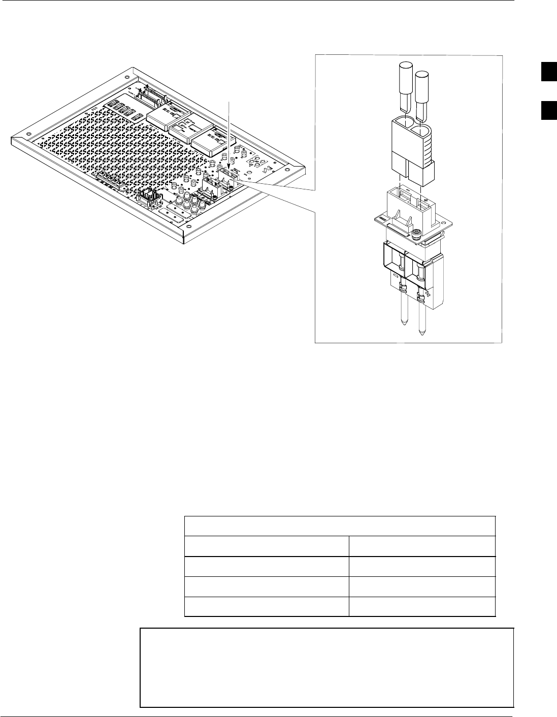
BTS Power Cabling
68P64115A19–4
Mar 2003 1X SC 4812T-MC BTS Hardware Installation - Software Release R2.16.1.x
CONTROLLED INTRODUCTION
2-47
Figure 2-23: DC Power Connector/Filter
ti-CDMA-WP-00194-v01-ildoc-ftw
Input
Connector/
DC Filter
2nd DC FILTER
OPTIONAL
(–) (+)
DC
Connector
Housing
DC
CONTACT
(+) DC CABLE
DC CABLE (–)
DC
CONTACT
Tools and Equipment Required
The following tools are required to install the power cable on the BTS:
Cable M – The cable diameter and lug style depend on the length of
cable required. Appropriate codes and standards must be followed to
determine the correct wire size and type (see Table 2-35). A variety of
lug sizes are available from Motorola for the various cable sizes and
types that may be selected (see Table 2-36).
Table 2-36: Lug Part Numbers
Lug Part Numbers Cable Type
CGDS6320G1 AWG 2/0
CGDS6320G5 AWG 3/0
CGDS6320G2 AWG 4/0
NOTE The cable diameter and lug style depend on the length of cable
required. Appropriate codes and standards MUST be followed to
determine the correct wire size and type. A variety of lug sizes
are available from Motorola for the various cable sizes and types
that may be selected. Lug size is dependent on the gauge and
type of cable selected for the frame power feed.
2
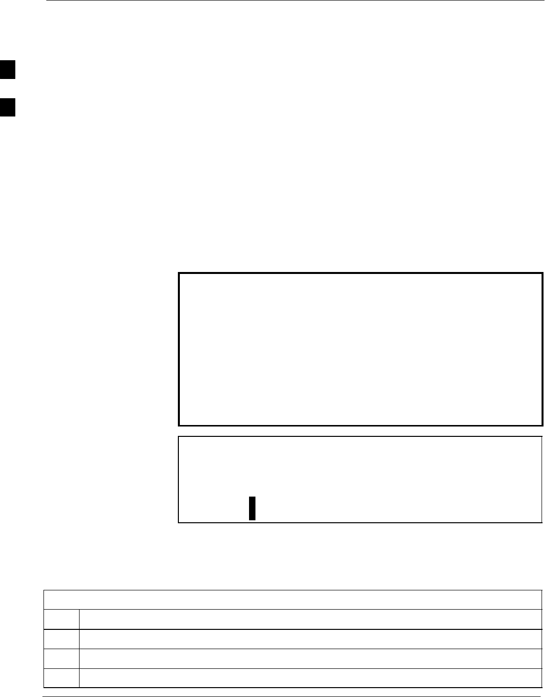
BTS Power Cabling 68P64115A19–4
Mar 2003
1X SC 4812T-MC BTS Hardware Installation - Software Release R2.16.1.x
CONTROLLED INTRODUCTION
2-48
Recommended Crimper Tool – The following three crimper tools
are recommended to assemble the customer-side connector for the DC
cables. Choose one of the following crimper tools, according to site
requirements and preferences.
SAMP 600850 – maximum cable size of #4/0 (mechanical hand tool)
SSMH p/n SY283 – maximum cable size of #4/0 (mechanical hand
tool)
SAnderson Power Products (APP) p/n 1368 – can accommodate cable
sizes up to 300 MCM (hydralic hand crimp tool).
Pre-connection Checklist
At this point in the installation ensure that the cabinet is NOT already
connected to the main dc power source.
Installing Power Cables
Read the Power Cable Installation WARNINGS and CAUTIONS before
going to Table 2-37 (+27 V Power Cable Installation) also review
Figure 2-23.
WARNING SFailure to observe these warnings could cause electrical
shock to personnel and/or damage to equipment!
SDo NOT wear a wrist strap when servicing the power
supplies or power distribution cabling! Serious personal
injury can result.
SThe external converter supplying the cabinet must have
double or reinforced insulation between its primary and
secondary circuits, and must conform to Safety Standard
EN60 950.
SEnsure the source for the DC voltage is in the OFF position
prior to attempting to connect the dc voltage.
CAUTION SEnsure all frame power supply circuit breakers are OFF.
SPerform any adjustments recommended by the manufacturer
on the main power supply equipment before connecting dc
power cables to the main dc power source.
SInput to the base station must remain between +34 V and
+21 V dc for +27 V dc operation.
BTS Power Cabling for + 27 V Configuration
The cable connections for powering a +27 V BTS are presented in
Table 2-37.
Table 2-37: Procedure to Install BTS +27 V Power Cables
Step Action
1Ensure the DC power cables are NOT connected to the main DC power source.
2Remove the components from the dc connector package shipped with the BTS.
3Strip 35 mm of insulation from the negative (–) and positive (+) power cables.
2

BTS Power Cabling
68P64115A19–4
Mar 2003 1X SC 4812T-MC BTS Hardware Installation - Software Release R2.16.1.x
CONTROLLED INTRODUCTION
2-49
Table 2-37: Procedure to Install BTS +27 V Power Cables
Step Action
4Place a dc contact on the negative (–) and positive (+) dc cables.
5Using the appropriate crimping tool, crimp the dc contact to the dc cables.
6Observe the negative (–) and positive (+) cables and insert the dc contacts into the dc connector
housing(s) until an audible click is heard.
7Verify the positive (+) cable is installed in the positive position and the negative (–) cable is installed
in the negative (–) position on the connector housing(s).
8Ensure the cables are firmly fastened to the dc connector housing(s).
9Connect the DC connector housing to the mating input connector/DC filter on the BTS (see
Figure 2-23).
10 Connect the DC connector housing to the mating input connector/DC filter on the BTS for the second
dc filter feed, if required (see Figure 2-23).
11 Are there additional frames that require cable installation?
– If YES, repeat the above procedure for the additional frame(s).
– If NO, this procedure is complete.
2

Mar 2003 1X SC 4812T-MC BTS Hardware Installation - Software Release R2.16.1.x
CONTROLLED INTRODUCTION
3-1
Chapter 3
Expansion Frame Cabling and
Installation
3

Expansion Frame (+27 V BTS Configuration) 68P64115A19–4
Mar 2003
1X SC 4812T-MC BTS Hardware Installation - Software Release R2.16.1.x
CONTROLLED INTRODUCTION
3-2
Expansion Frame (+27 V BTS Configuration)
This chapter provides the procedures for installing an Expansion frame
to either a SC4812T or SC 4812T–MC Starter frame.
Installation Procedures
This chapter includes installation and setup procedures for the following:
SRF Cabling (TX & RX)
SRF GPS
SRemote GPS Distribution (RGD)
SHSOX
SLocal Area Network (LAN)
SC-CCP Cage Dip Switch Settings
Inter-frame Cables
Sites utilizing Expansion frames require certain procedures to be
completed (depending on site requirements) before proper operation can
be obtained. The BTS cable description and part numbers for certain
different procedures are listed in Table 3-1. The letters, referenced under
the Cable Label column in Table 3-1, are used as a reference for all
cabling procedures and diagrams in this manual. This information
applies to all system configurations.
Table 3-1: Expansion Cable/Hardware Descriptions and Part Numbers
Cable
Label Part
Number Description
A1T472Ax RGD Antenna punch block cable; where x=A–F for different A1 cable lengths
(50 to 2000 ft).
A23086433H07 Punch block to RGD Site I/O board cable
B 3086433H02 RGD Expansion cable
C 3086433H01 RGD to Site I/O cable
D 3086458H01 HSOX cable
E 3086412H01 RF Expansion cable
F 1586370H01 Harting; 12 pack
M N.A. Power cable – See Power Cable section, for detailed information on cable
termination lugs. Customer supplied cable.
Before You Begin
Ensure each Starter and/or Expansion frame has been properly powered
off before performing any installation procedures.
3
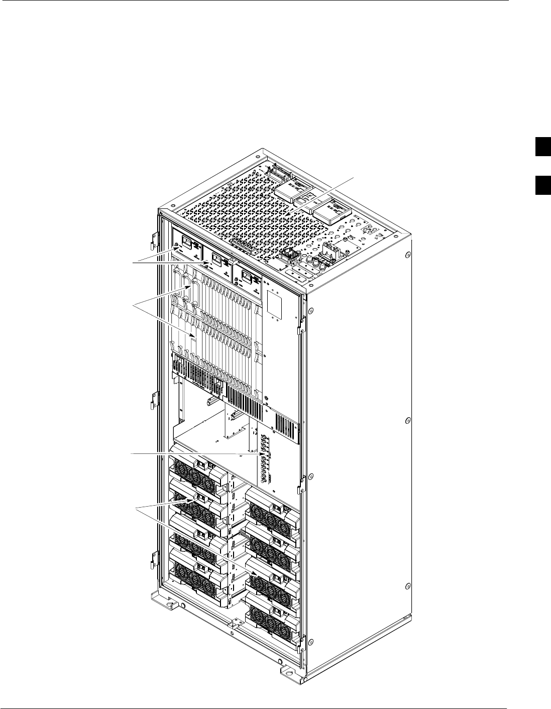
Expansion Frame (+27 V BTS Configuration)
68P64115A19–4
Mar 2003 1X SC 4812T-MC BTS Hardware Installation - Software Release R2.16.1.x
CONTROLLED INTRODUCTION
3-3
Expansion Frame and Expansion I/O Plate
Figure 3-1 shows the SC 4812T–MC BTS that can be used as an
expansion frame and Figure 3-2 that shows a detailed version of the
Expansion I/O plate for the +27 V configuration.
Figure 3-1:BTS MC Expansion Frame (+27 V Configuration)
For clarity, doors are not shown.
I/O Interconnect
C–CCP Cage
Fan Module
ti-CDMA-WP-00205-v01-ildoc-ftw
C–CCP Cage
Power
and PA Breakers
Amplifier
Cage
Plate
3
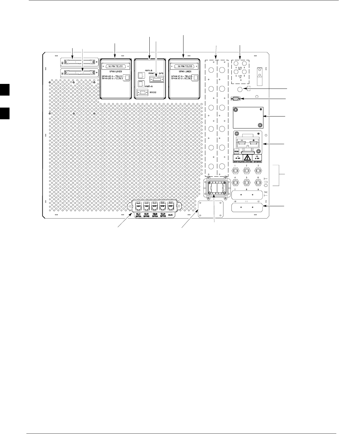
Expansion Frame (+27 V BTS Configuration) 68P64115A19–4
Mar 2003
1X SC 4812T-MC BTS Hardware Installation - Software Release R2.16.1.x
CONTROLLED INTRODUCTION
3-4
Figure 3-2: Expansion Frame I/O Plate (+27 V Configuration)
FRONT
SPAN I/O
SITE I/O
ALARM
CONNECTORS
LAN
CONNECTIONS
RF GPS IN
3 TO 6 TRANSMIT
ANTENNA
CONNECTORS
DEPENDING ON
CONFIGURATION
HSO/LFR
FILLER PLATE
RECEIVE
ANTENNA
COVERS
INPUT
CONNECTOR/
DC FILTER
ETHERNET ROUTER (IF USED;
OTHERWISE, FILLER PLATE) EXP OUT
FILLER PLATE
3A
2A
1A
6A
5A
4A
3B
2B
1B
6B
5B
4B
REAR
2 TO 3
TRANSMIT
ANTENNA FILLER
PLATES
DEPENDING ON
CONFIGURATION
SPAN I/O A SITE I/O SPAN I/O B
ALARM B
SPAN I/O A
SPAN I/O B
ALARM A
SITE I/O
GND
DC FILTER 2
RX
RX
DC FILTER 1
SPAN I/O
RF EXPANSION PORT
FROM STARTER BTS
ti-CDMA-WP-00189-v01-ildoc-ftw–REF
RGPS
3
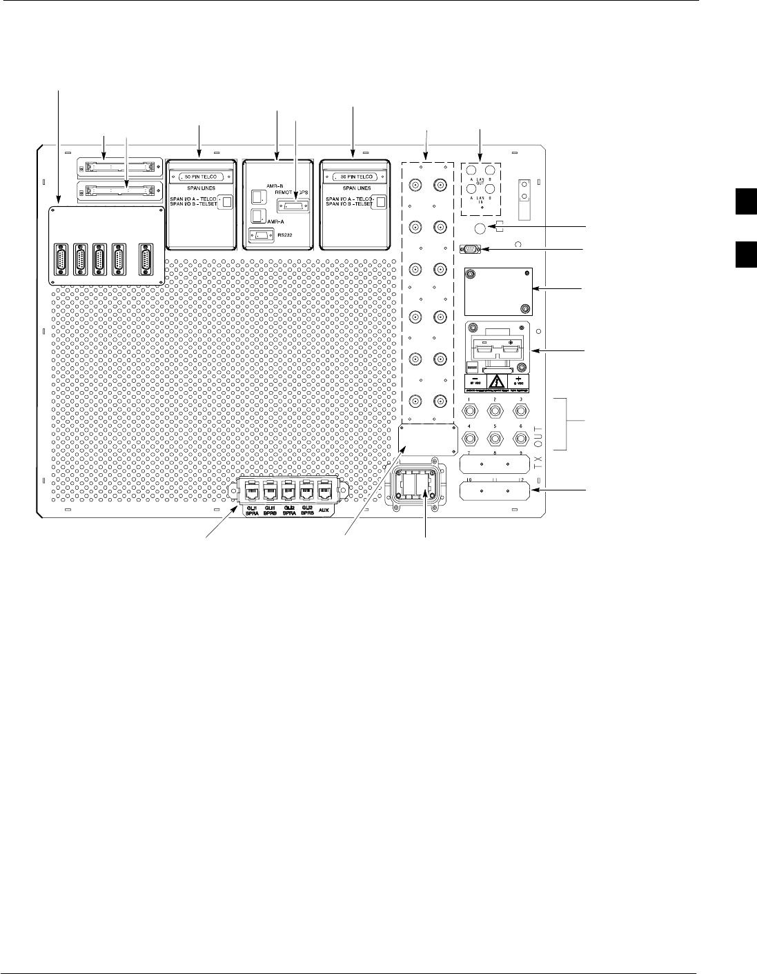
Expansion Frame (+27 V BTS Configuration)
68P64115A19–4
Mar 2003 1X SC 4812T-MC BTS Hardware Installation - Software Release R2.16.1.x
CONTROLLED INTRODUCTION
3-5
Figure 3-3: Starter Frame I/O Plate
FRONT
SPAN I/O
SITE I/O
ALARM
CONNECTORS
LAN
CONNECTIONS
RF GPS IN
3 TO 6 TRANSMIT
ANTENNA
CONNECTORS
DEPENDING ON
CONFIGURATION
HSO/LFR
FILLER PLATE
RECEIVE
ANTENNA
CONNECTORS
INPUT
CONNECTOR/
DC FILTER
ETHERNET ROUTER (IF USED;
OTHERWISE, FILLER PLATE) EXP IN FILLER
PLATE
3A
2A
1A
6A
5A
4A
3B
2B
1B
6B
5B
4B
REAR
2 TO 3
TRANSMIT
ANTENNA FILLER
PLATES
DEPENDING ON
CONFIGURATION
SPAN I/O A SITE I/O SPAN I/O B
ALARM B
SPAN I/O A
SPAN I/O B
ALARM A
SITE I/O
GND
DC FILTER 2
RX
RX
DC FILTER 1
SPAN I/O
REMOTE GPS DISTRIBUTION (RGD) MODULE –
USED ONLY IF EXPANSION FRAME(S) INSTALLED
RF EXPANSION PORT TO ANOTHER
BTS (USED ONLY IF EXPANSION FRAME
INSTALLED; OTHERWISE, FILLER PLATE
INSTALLED)
ti-CDMA-WP-00188-v01-ildoc-ftwREF
RGPS
3
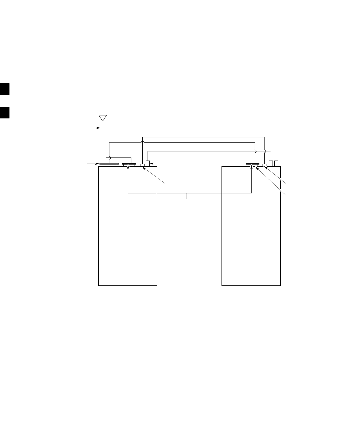
Expansion Frame (+27 V BTS Configuration) 68P64115A19–4
Mar 2003
1X SC 4812T-MC BTS Hardware Installation - Software Release R2.16.1.x
CONTROLLED INTRODUCTION
3-6
Cable Labels
The cable designations are referenced to Table 2-13 in “Cable
Description and Part Numbers”.
Expansion Frame Cabling Diagram
Figure 3-4 illustrates the BTS Expansion Frame cabling details with the RF
GPS or Remote GPS option.
Figure 3-4: Expansion Frame Cabling Details
LFR/HSO
(9 Pin D)
Site I/O
Harting 12 PK
RF Expansion Cable
RGD PCB
Remote GPS
Antenna
Starter
Frame Expansion
Frame
LFR/HSO
(9 Pin D)
D
B
E
C
A2
A1
Lighting Protected
Punch block
ti-CDMA-WP-00088-v01-ildoc-ftw
Remote GPS
REF
3
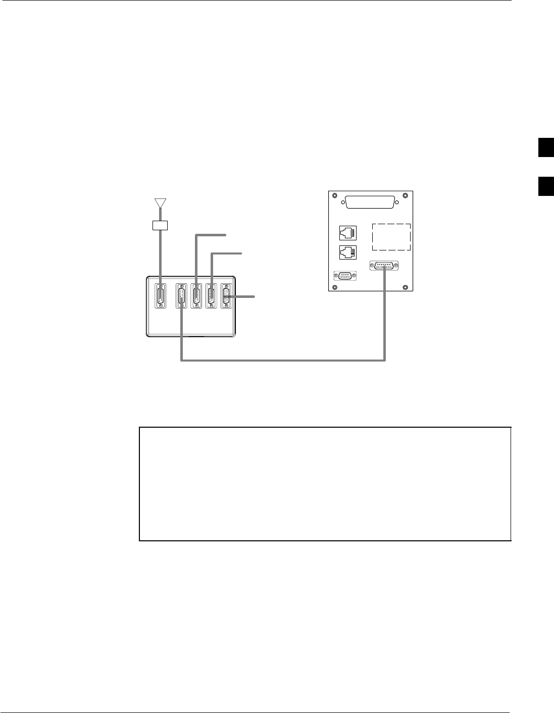
Expansion Frame Inter-Frame Cabling
68P64115A19–4
Mar 2003 1X SC 4812T-MC BTS Hardware Installation - Software Release R2.16.1.x
CONTROLLED INTRODUCTION
3-7
Expansion Frame Inter-Frame Cabling
This section describes the connections between an expansion frame with
a starter frame.
Remote GPS Distribution (RGD) Board Diagram
Figure 3-5 shows the RGD board cable connections. Both RGD and Site
I/O boards are on the strater BTS. Table 3-1 provides a description of all
cables associated with the installation of RGD.
Figure 3-5: RGD Board Cable Connections
NOTE:
RGD card is required on the Starter frame only.
It provides Remote GPS signal to the Expansion frame.
RGD
To Expansion Frame
Not used
(Main out)
Remote GPS Antenna
Not used
Surge Protected
Punch block
Site I/O
ti-CDMA-WP-00087-v01-ildoc-ftw–REF
A1
A2
B
C
NOTE SCables A1 and A2 must be punched into the punch block as
if they were part of the same cable, cut in the middle. The
same colors must be punched on both sides of the punch
block.
SFrame MUST be equipped with CSM2 for Remote GPS
operations.
SRemote GPS is NOT supported in all Motorola 4-digit
frames.
3
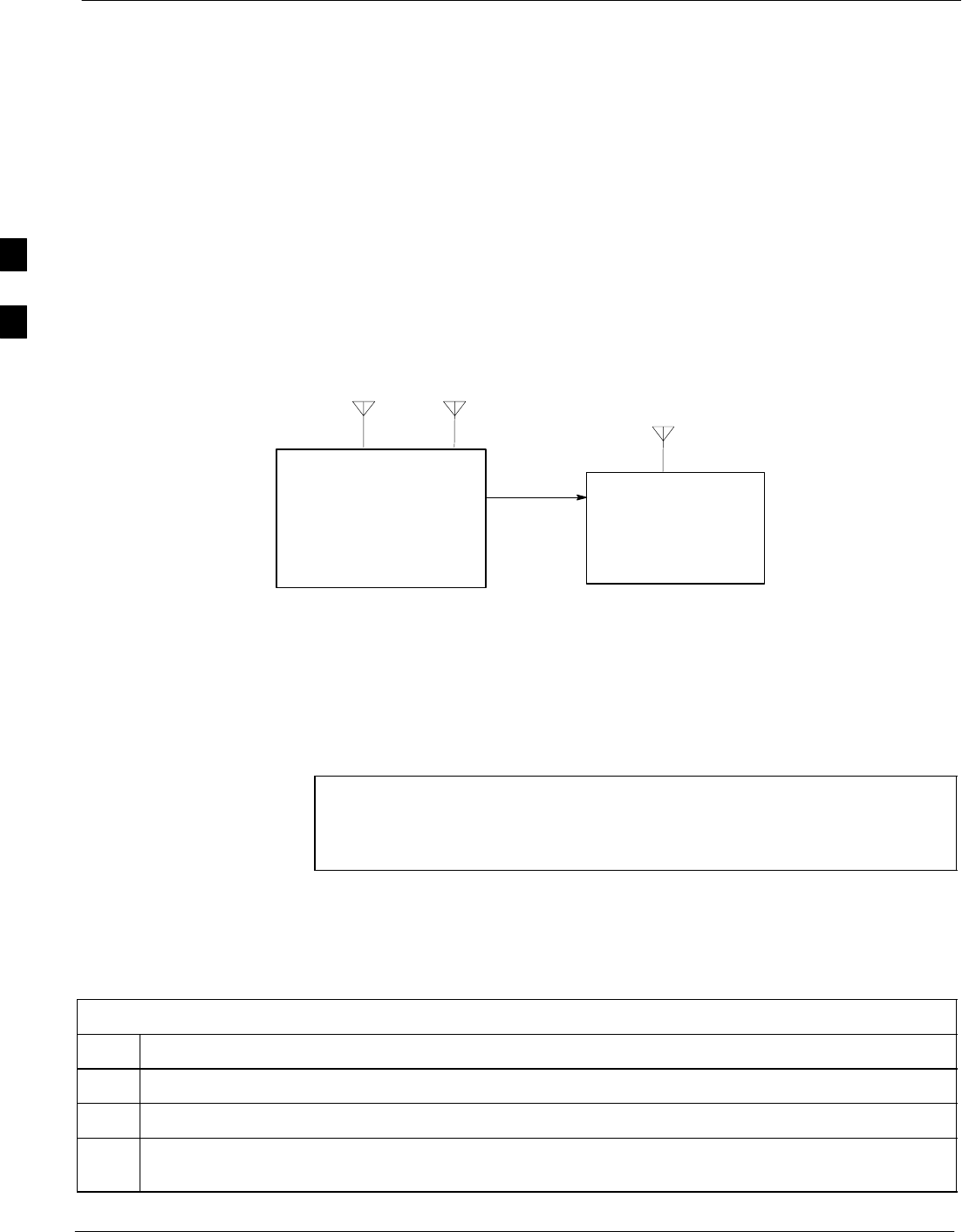
Expansion of the +27 V Frame 68P64115A19–4
Mar 2003
1X SC 4812T-MC BTS Hardware Installation - Software Release R2.16.1.x
CONTROLLED INTRODUCTION
3-8
Expansion of the +27 V Frame
Site configurations can include a +27 V SC 4812T–MC BTS Starter
Frame using either a +27 V SC 4812T–MC BTS frame or a +27 V SC
4812T BTS as an Expansion frame.
Another site configuration can include a +27 V SC 4812T BTS Starter
Frame using a +27 V SC 4812T–MC BTS frame as an Expansion frame.
Antenna Sharing
Separate TX antennas are used in each frame. One Expansion frame can
share RX antennas with the Starter Frame. RX antenna sharing is shown
in Figure 3-6.
Figure 3-6: RX Antenna Sharing with an Expansion Frame
RX
EXP.
OUT
RX
EXP.
IN
RX
TX
TX
Starter Frame Expansion Frame
ti-CDMA-WP-00056-v01-ildoc-ftw–REFREF
Tools Required
ST10 and T30 Torx bits and driver
SFlat head screwdriver or 5/16” Hex socket
STorque driver
NOTE Use the following procedures to add an Expansion frame to a
Starter frame. The instructions are identical when connecting a
SC 4812T–MC BTS “Expansion” frame to either a SC 4812T or
SC4812T–MC BTS “Starter” frame.
Expansion Procedure
Table 3-2 provides the procedures necessary to install a SC 4812T–MC
BTS Expansion Frame to a Starter frame.
Table 3-2: Installing an Expansion BTS
Step Action
1Confirm the BTS is powered down.
2Locate the Expansion I/O Filler Plate on the Starter Frame I/O plate (see Figure 3-3).
3Using the Torx T10 bit, remove four M3 screws attaching the Expansion I/O Filler Plate to the I/O
plate. (The filler plate can be discarded.)
. . . continued on next page
3

Expansion of the +27 V Frame
68P64115A19–4
Mar 2003 1X SC 4812T-MC BTS Hardware Installation - Software Release R2.16.1.x
CONTROLLED INTRODUCTION
3-9
Table 3-2: Installing an Expansion BTS
Step Action
4Install the Expansion I/O Housing on the Starter I/O in the same area as the filler plate.
5Secure the housing to the I/O plate by using four M3x10 screws, T10 Torx bit and torque to
10–12 in-lb. The label FRONT on the Expansion I/O housing should face EXP I/O text on the
I/O plate.
6Using the T30 bit, remove the eight M6 screws attaching the front cosmetic panel to the cabinet.
7Locate the two Expansion OUT cables tie-wrapped behind the front cosmetic panel.
8Remove Harting terminators, if present, on the Expansion out cables.
9Carefully cut the tie-wrap, taking care as not to cut cables, and insert the cables into the Expansion
I/O housing from below the I/O plate. Note the cables are keyed, and can only be installed one way in
the Expansion I/O housing. Confirm the cables are fully snapped into place in the Expansion I/O
housing.
10 Attach the front cosmetic panel to the cabinet using the eight M6 screws torqued to 45 in-lb.
11 Install one end of the RF expansion cable (see Figure 3-4) to the Starter frame by plugging the end of
the cable labeled SC 4812T into the Expansion I/O housing labeled EXP I/O, located on the Starter
frame I/O plate (see Figure 3-3). The cable is keyed and can only be installed one way.
12 Secure the connection by fastening the four retention screws of the cable into the Expansion I/O
housing. The screws should be fastened to 20 in-lb torque using a flat head screwdriver or a 5/16”
socket and ratchet.
13 Following the same procedure, install the other end of the RF expansion cable, labeled SC 4812T
EXP to the expansion housing labeled EXP I/O on the +27 V SC 4812T (1800 mm) Expansion
frame I/O plate (see Figure 3-2).
3

RF GPS Expansion Installation
Mar 2003
1X SC 4812T-MC BTS Hardware Installation - Software Release R2.16.1.x
CONTROLLED INTRODUCTION
3-10
RF GPS Expansion Installation
GPS Expansion
The Global Positioning System (GPS) is used by Motorola as the
primary means to synchronize all base stations in a CDMA cellular
system. The GPS signal is the input to the CSM, which develops the
timing references for the Base Transceiver system (BTS). Every BTS at
a site requires a GPS input.
On some versions of the SC 4812T product, GPS timing is provided by
a built-in dedicated RF GPS receiver module installed on the CSM. On
BTSs equipped with redundancy, two (2) CSMs are installed.
On some versions of the SC 4812T product, GPS timing is provided by
an optional Remote GPS receiver (RGPS). The RGD card accepts timing
information in digital format from the RGPS head and distributes it
within the BTS, and to other Expansion cabinets by a small digital cable.
The procedure for RGPS is covered in a separate section.
Customer Equipment Considerations and System Constrains
In order to share RF GPS signals, customer equipment external to the
BTS must be carefully designed to ensure that overall performance is not
degraded. Both the gain and the noise of the complete system affect the
performance and the A/D converter in the GPS receiver. A typical
diagram of a system to feed multiple BTSs from one GPS antenna is
shown in Figure 3-7.
RF RGPS Expansion Installation Considerations
Following are recommendations for the RF GPS distributing amplifier
method:
SThe maximum GPS system NF is 4 dB, per OnCore Technical
Application Note (CSM GPS Vendor).
SGPS distributed amplifier is acceptable, but only with Motorola
recommended parts.
SRecommended amplifier model number is HP58516A (4–way).
SMust have surge protection before the distribution amplifier
(PolyPhaser number is IS–MR50LNZ–6–MA).
SMaximum cable loss between GPS antenna and BTS is 4.5 dB.
SMaximum cable length difference between the 4:1 splitter to any
cabinet is 8 meters.
3
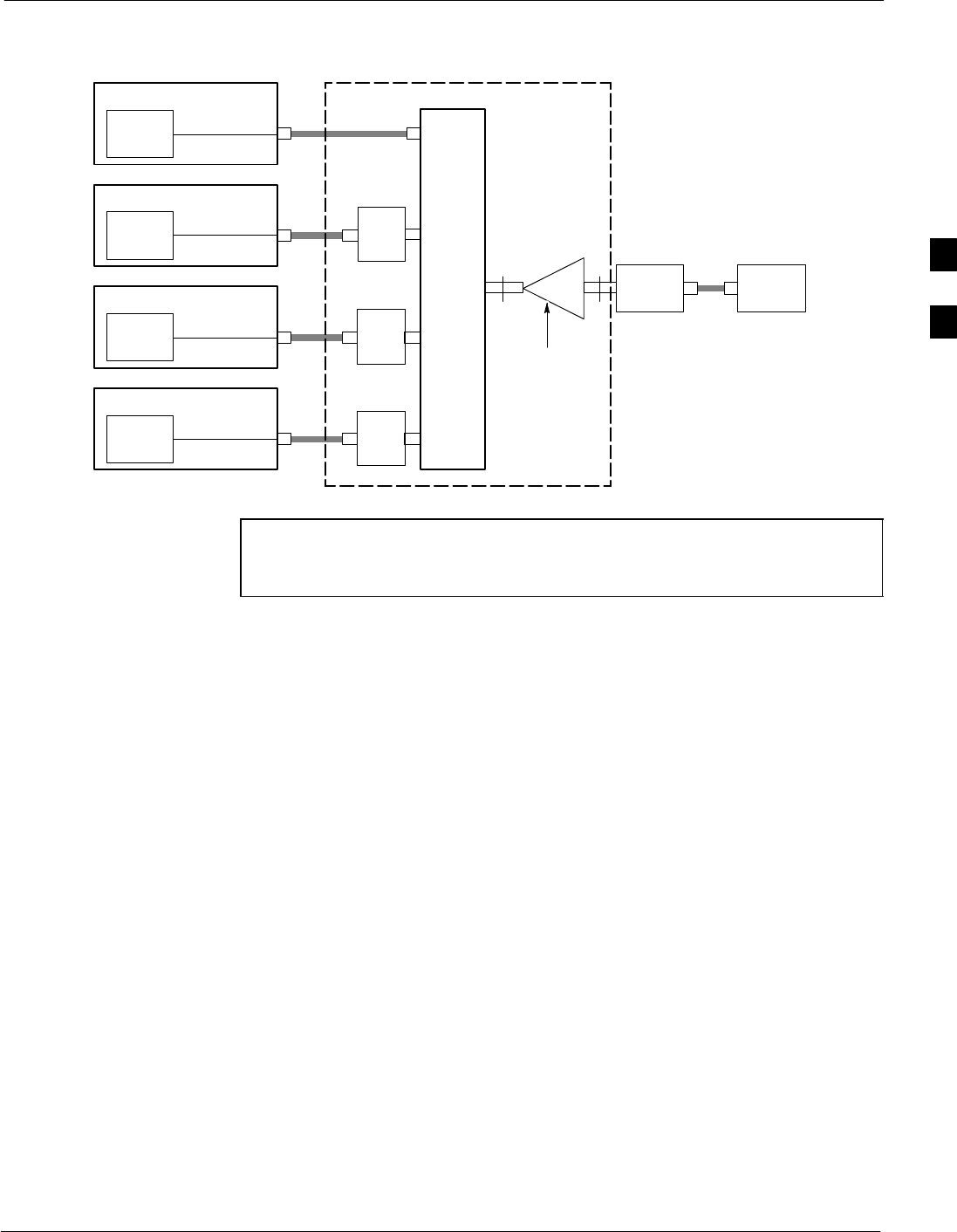
RF GPS Expansion Installation
68P64115A19–4
Mar 2003 1X SC 4812T-MC BTS Hardware Installation - Software Release R2.16.1.x
CONTROLLED INTRODUCTION
3-11
Figure 3-7: System to Feed Multiple BTS’s from One RF GPS Antenna
GPS
Receiver
BTS
GPS
Receiver
BTS
GPS
Receiver
BTS
GPS
Receiver
BTS
Antenna /
LNA
DC
Block
DC
Block
DC
Block
4-Way
Splitter Preamp Lightning
Arrestor
w/ DC Pass
Through
Note: Motorola P/N is CGDSHP58516A
(HP P/N is HP58516A). Can be used to
replace all parts in box.
ti-CDMA-WP-00028-v01-ildoc-ftw
NOTE – Maximum cable loss is 4.5 dB with or without 4:1 splitter.
– HP58516A replaces all three components (DC Block,
Splitter, and Pre-amplifier.
3

Remote GPS Distribution Expansion 68P64115A19–4
Mar 2003
1X SC 4812T-MC BTS Hardware Installation - Software Release R2.16.1.x
CONTROLLED INTRODUCTION
3-12
Remote GPS Distribution Expansion
Configuration
RGD and Remote GPS Expansion
Tools Required
ST10 Torx bit
SFlat head screwdriver
STorque driver
Remote GPS (RGD) Expansion Procedure
The Remote GPS Expansion procedure is listed in Table 3-3 and
Figure 3-8 shows the RGD board cable connections.
Table 3-3: Installing Remote GPS (RGD) Expansion
Step Action
1Install the RGD board on the I/O plate of the MC Starter frame of the cell site. The RGD board
mounting area on the frame I/O plate is shown in Figure 2-1 and Figure 2-2. Align the RGD board to
the I/O plate using six M3 screws, fastening the screws to 8–10 in-lb (0.9 – 1.1 N-m) using the T10
Torx bit and torque driver.
2Install the RGD cover over the board. Align the connector ports on the cover with the connectors on
the RGD board. The cover will snap into place.
3Install the Remote GPS IN cable. Plug the 15-pin D-sub end of the cable into the RGD board
connector labeled REMOTE GPS IN. This cable may have to be unplugged from the Starter frame
remote GPS connector on the Site I/O board (see Figure 3-3).
4Unfasten the cable connector retention screws using the flat head screwdriver to remove the cable.
5Secure the cable to the RGD board connector by fastening the cable connector retention screws using
the flat head screwdriver.
6Install the RGD to Site I/O cable (15 pin D-sub to 15-pin D-sub short ribbon cable). Plug either end of
the cable into the RGD board connector labeled MAIN OUT.
7Fasten the cable connector retention screws to 4–6 in-lbs (0.4 – 0.7 N-m) using the screwdriver.
8Fasten the other end of the cable to connector labeled REMOTE GPS on the Site I/O board (see
Figure 3-3).
9Fasten cable connector retention screws to 4–6 in-lbs (0.4 – 0.7 N-m) using the screwdriver.
10 Install the RGD expansion cable (15 pin D-sub to 15 pin D-sub long ribbon cable). Plug either end of
the cable into the RGD board connector labeled EXP 1 (see Figure 2-1).
11 Fasten cable connector retention screws to 4–6 in-lbs (0.4 – 0.7 N–m) using the screwdriver.
12 Plug the opposite end of the cable into the SC 4812T–MC Expansion Frame Remote GPS connector
on the Site I/O board (see Figure 2-2).
3

High Stability Oscillator Expansion (HSOX)
68P64115A19–4
Mar 2003 1X SC 4812T-MC BTS Hardware Installation - Software Release R2.16.1.x
CONTROLLED INTRODUCTION
3-13
High Stability Oscillator Expansion (HSOX)
Configuration
High Stability Oscillator Expansion (HSOX)
Tools Required
SFlat head screwdriver
HSO Expansion Procedure
Install the HSOX cable and card per instructions in Table 3-4.
Table 3-4: Installing the HSOX Cable and Card
Step Action
1Disconnect the LFR antenna cable from the HSO/LFR connector on the Starter Frame I/O plate, if
necessary.
2Install the HSO expansion cable (9-pin D-sub “Y” ribbon cable). Plug connector “B” of the HSO
expansion cable (see Figure 3-8) into the Starter Frame HSO/LFR input/output port on the I/O plate
(see Figure 2-1).
3Fasten the cable connector retention screws to 4–6 in-lb (0.4 – 0.7 N-m) using the flat head
screwdriver.
4If an LFR antenna is used, connect the LFR antenna cable to connector “C” (see Figure 3-8) of the
HSO expansion cable.
5Plug connector “A” of the HSO expansion cable (see Figure 3-8) into the Expansion Frame HSO/LFR
input/output port on the I/O plate (see Figure 2-2).
6Fasten the cable connector retention screws to 4–6 in-lbs (0.4 – 0.7 N-m) using the flat head
screwdriver.
7Attach a static wrist strap to your wrist and to the ESD plug on the BTS.
8Install the HSO expansion card into the appropriate HSO/LFR slot. Latch the top and bottom latches
at the same time to properly seat the card.
Figure 3-8: HSOX Cable (3086458H01) for Expansion Frame
LFR
CONNECTOR
RETENTION
SCREW
CONN A
CONN B
CONN C
LFR /
HSO
STARTER FRAME
I/O PLATE
LFR /
HSO
EXPANSION
FRAME
TO LFR
ANTENNA
ti-CDMA-WP-00029-v01-ildoc-ftw
3

Local Area Network (LAN) Expansion Installation
Mar 2003
1X SC 4812T-MC BTS Hardware Installation - Software Release R2.16.1.x
CONTROLLED INTRODUCTION
3-14
Local Area Network (LAN) Expansion Installation
Configuration
The LAN is only connected between frames in a BTS if the system is
running software revision 2.9 or later, and the site is configured as a
logical BTS.
NOTE C-CCP dip switch changes are required to reflect frame ID (refer
to Figure 3-10).
Tools Required
S5.5 mm Hex socket
Torque Specifications
Terminator grounding stud nut: 10–12 in-lbs (1.1 – 1.3 N-m).
LAN Expansion Installation Procedure
Table 3-5 provides the procedure to install LAN Expansion.
Table 3-5: Installing LAN Expansion
Step Action
1Remove the LAN OUT A and LAN OUT B terminators (BNC) located on the Starter frame I/O plate.
2Remove the LAN IN A and LAN IN B terminators (BNC) located on the Expansion frame I/O plate
through a conductive tether and lug attached to a grounding stud (see Figure 3-9).
3To remove the lug of the tether from the grounding stud, remove the nut and washer from the
grounding stud using a 5.5 mm hex socket and ratchet. Slide the lug off the stud.
4Reinstall the nut and washer on the grounding stud, tightening the nut to 8–10 in-lbs using the 5.5 mm
hex socket and torque ratchet.
5Install the frame-to-frame LAN cables by plugging one end of a BNC cable into the LAN OUT B
connector on the Starter Frame I/O plate. Plug the opposite ends of the cables into the appropriate
LAN IN (A and B) connector on the Expansion Frame I/O plate.
3
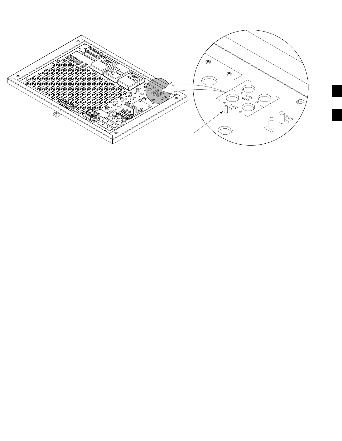
Local Area Network (LAN) Expansion Installation
68P64115A19–4
Mar 2003 1X SC 4812T-MC BTS Hardware Installation - Software Release R2.16.1.x
CONTROLLED INTRODUCTION
3-15
Figure 3-9: LAN Grounding Stud
ti-CDMA-WP-00215-v01-ildoc-ftw
I/O PLATE
LAN
CONNECTIONS
LAN GROUND
STUD
3
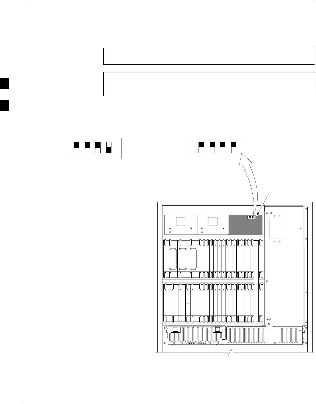
Setting Frame C-CCP Shelf Configuration Switch 68P64115A19–4
Mar 2003
1X SC 4812T-MC BTS Hardware Installation - Software Release R2.16.1.x
CONTROLLED INTRODUCTION
3-16
Setting Frame C-CCP Shelf Configuration Switch
When the frame is a Starter BTS, the backplane switch settings behind
the fan module nearest the breaker panel must be set to the ON position
(see Figure 3-10).
NOTE The switch setting must be verified and set before power is
applied to the BTS equipment!
NOTE Dip switch settings are only changed in the Expansion frame if
the system is running software release 2.9 or later, AND the site
is configured as a logical BTS.
Figure 3-10: Backplane DIP Switch Settings
19 mm Filter Panel
Power Supply
AMR / MACH
HSO
CSM
CSM
39 mm Filter Panel
AMR / MACH
GLI–1GLI–2
MCC–6
BBX–1
BBX–2
BBX–3
BBX–4
BBX–5
BBX–6
BBX–R
Switch
MPCMPC
MCIO
BBX–7
BBX–8
BBX–9
BBX–10
BBX–11
BBX–12
MCC–5
MCC–4
MCC–3
MCC–2
MCC–1
MCC–12
MCC–11
MCC–10
MCC–9
MCC–8
MCC–7
Power Supply
Power Supply
CCD CCD
ON
OFF
SC 4812T–MC C–CCP SHELF
FAN MODULE
REMOVED
STARTER
FRAME
SETTING
ON
OFF
EXPANSION
FRAME
SETTING
BOTTOM / TOP
RIGHT / LEFT
MODEM_FRAME_ID_1
MODEM_FRAME_ID_0
BOTTOM / TOP
RIGHT / LEFT
MODEM_FRAME_ID_1
MODEM_FRAME_ID_0
ti-CDMA-WP-00211-v01-ildoc-ftw
SPEED
CONTROLLED
FAN
MODULE
REAR
FRONT PWR/ALM
SPEED
CONTROLLED
FAN
MODULE
REAR
FRONT PWR/ALM
3

Mar 2003 1X SC 4812T-MC BTS Hardware Installation - Software Release R2.16.1.x
CONTROLLED INTRODUCTION
4-1
Chapter 4
Optional Equipment
4
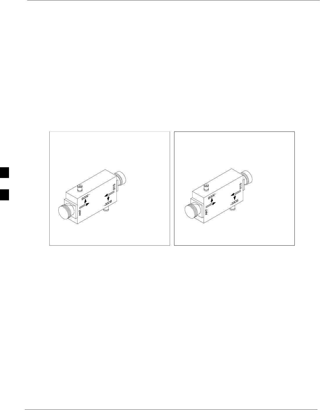
Optional BTS Equipment Identification 68P64115A19–4
Mar 2003
1X SC 4812T-MC BTS Hardware Installation - Software Release R2.16.1.x
CONTROLLED INTRODUCTION
4-2
Optional BTS Equipment Identification
Overview
This section of the manual provides identification of the optional
BTS equipment and helpful information when installing the equipment.
Directional Couplers
Directional couplers are used when an external RFDS is used.
Directional couplers are not used at sites where duplexed antennas are
desired. Figure 4-1 depicts the directional couplers and their identifying
connections.
Figure 4-1: Directional Couplers
FORWARD PORT
(SMA TYPE) TO RFDS
REFLECTED PORT
(SMA TYPE) TO RFDS
INPUT PORT FROM BTS
FRAME (N TYPE)
OUTPUT PORT TO TX
ANTENNA FEEDS
(N TYPE OR 7/16)
TX ANTENNA DIRECTIONAL
COUPLER CONNECTION DETAIL
(frame mount orientation)
INPUT PORT FROM
ANTENNA (N TYPE OR
7/16)
REFLECTED PORT
(SMA TYPE) TO RFDS
FORWARD PORT
(SMA TYPE) TO RFDS OUTPUT PORT TO BTS
FRAME (N TYPE)
RX ANTENNA DIRECTIONAL
COUPLER CONNECTION DETAIL
(frame mount orientation)
ti-CDMA-WP-00126-v01-ildoc-ftw
4
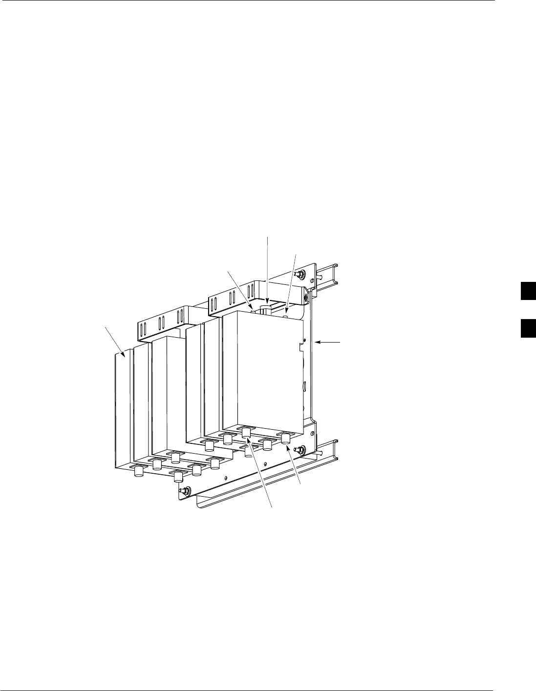
Optional BTS Equipment Identification
68P64115A19–4
Mar 2003 1X SC 4812T-MC BTS Hardware Installation - Software Release R2.16.1.x
CONTROLLED INTRODUCTION
4-3
Duplex Directional Couplers (DDC) and Mounting Bracket
Duplex directional couplers (DDCs) are used when it is desired to
duplex transmit and receive antennas. This device incorporates
directional coupler function so separate directional couplers are not
required.
The Universal Bracket is designed for mounting on a 19-inch rack, to the
wall, or on a cable ladder. This bracket is 19 x 15 inches and can
accommodate up to six sets of DDCs (or directional couplers). After the
DDCs are mounted on the Universal Bracket, the whole assembly will
extend 6-1/2 inches from the mounting surface.
Figure 4-2 shows the Duplex Directional Couplers (mounted in the
universal mounting bracket) and identifies the connections.
Figure 4-2: DDC (Duplexers – Directional Couplers)
ANT COUPLED
PORT – REFLECTED
BTS COUPLED
PORT – FORWARD
ANTENNA
RX TO BTS
(RFM)
TX FROM
BTS (RFM)
UNIVERSAL
BRACKET
DDCs
ti-CDMA-WP-00063-v01-ildoc-ftw–REF
4

Optional BTS Equipment Identification 68P64115A19–4
Mar 2003
1X SC 4812T-MC BTS Hardware Installation - Software Release R2.16.1.x
CONTROLLED INTRODUCTION
4-4
RFDS The CDMA RFDS equipment operates in the CDMA radio frequency
spectrum. Refer to Table 4-1 for the CDMA frequency spectrums.
Table 4-1: CDMA Frequency Spectrum in MHz
Direction 800 MHz Band
Receive 824 – 849
Transmit 869 – 894
RF Interfaces RFDS interfacing is through directional couplers. The CDMA RFDS
equipment connects to coupled ports of directional couplers, cabled into
the Base Transceiver Station (BTS) site RX and TX antenna paths. The
coupled port connections provide the RF signal interface between the RF
diagnostic function and the following:
SSite RX antennas and the site receiver equipment
SSite TX antennas and the site transmitter equipment
RFDS Function
The CDMA RFDS equipment, operating under software control, is used
to test and verify operation of:
SSite RX and TX antenna path equipment including the antenna, filter,
antenna path equipment in the BTS, any RF cabling, etc.
SBTS broadband transceivers (BBXs)
STX Power amplifiers
SCall paths, including:
– uplink over the RX antenna path through the BTS
– downlink over the TX antenna path through the BTS
CDMA RFDS tests can be operated automatically at scheduled times to
run a battery of tests, or manually, performing one test at a time.
Complete testing covers each antenna path and its associated
transceivers.
CDMA RFDS testing is controlled from either the Local Maintenance
Facility (LMF) computer, or the control entity Operations &
Maintenance Center-Radio (OMC-R) for CDMA which evokes the test
and displays the results.
The CDMA RFDS equipment essentially monitors a TX antenna path
for TX RF signals and generates RX RF signals into an RX antenna
path.
For testing accuracy and repeatability, all RF monitoring and signal
generation is via conductive paths and not radiated through the air.
Therefore, if the site is equipped with an RF Diagnostic Sub-system,
each RX and TX antenna path is configured with a directional coupler
which is the RF signal interface between the RFDS and the antenna path.
The RFDS (see Figure 4-3) is rack mounted next to the 1X SC 4812T
BTS. For detailed information on installation and operation please order
the RFDS Users Guide (Motorola part no. 68P64113A37).
4
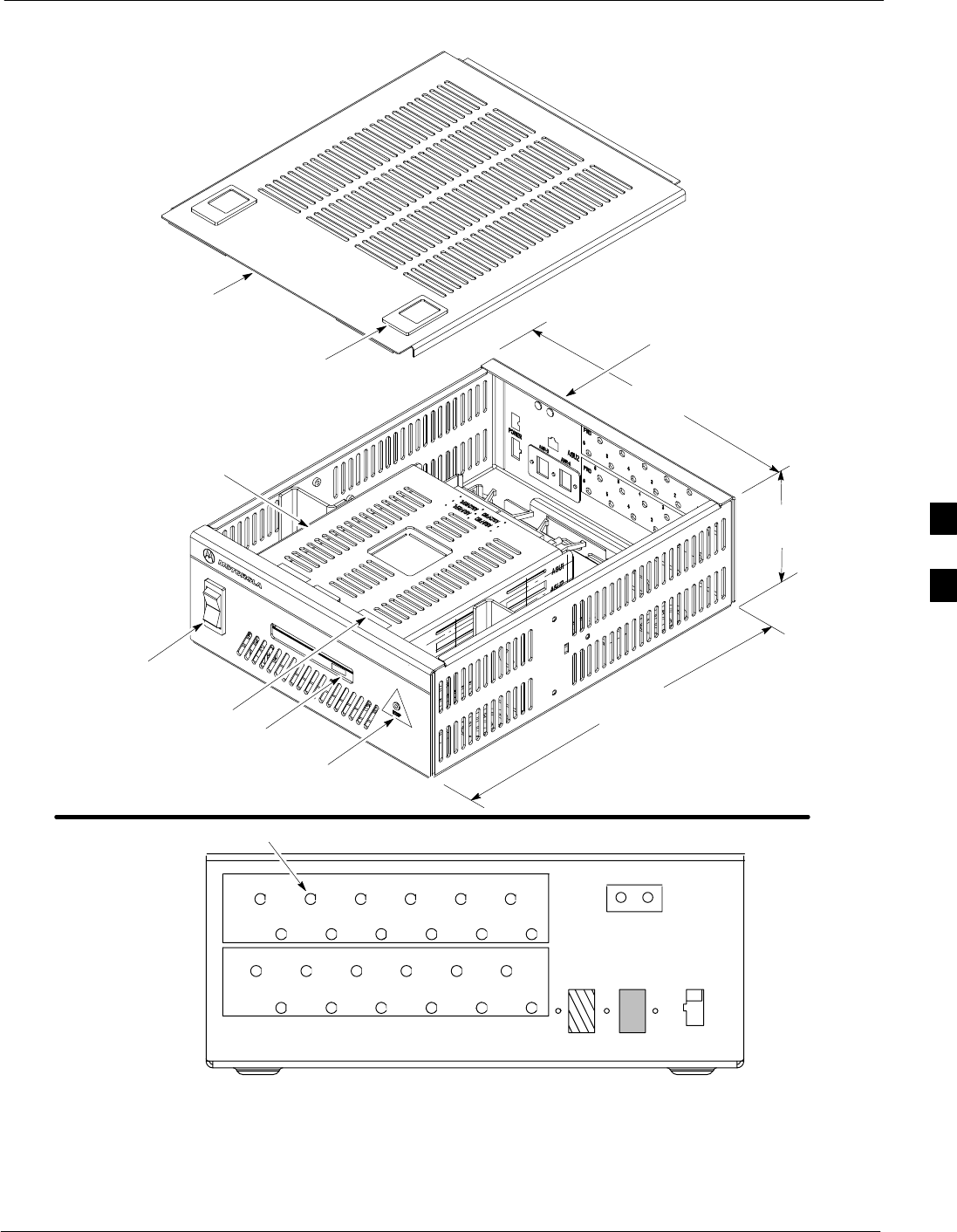
Optional BTS Equipment Identification
68P64115A19–4
Mar 2003 1X SC 4812T-MC BTS Hardware Installation - Software Release R2.16.1.x
CONTROLLED INTRODUCTION
4-5
Figure 4-3: RFDS (Rack Mount Unit)
TOP COVER
FRONT VIEW
(SHOWN WITH COVER OFF)
REAR VIEW
POWER SWITCH
ESD PLUG
SMA CONNECTORS
TOP COVER LATCH (2)
REFL
(ANT)
FWD
(BTS)
REFL
(ANT)
FWD
(BTS)
123456
123456
123456
123456
GND
AMR–A AMR–B POWER
27
VOLTS
DC
–
+
ASU1
ASU2
REAR VIEW
(SEE BELOW)
MMI PORT
FIELD REPLACEABLE
UNIT (FRU)
ESN LABEL
423.1 MM
(16.7 IN)
127.0 MM
(5.0 IN)
322.0 MM
(12.7 IN)
FW00529
4
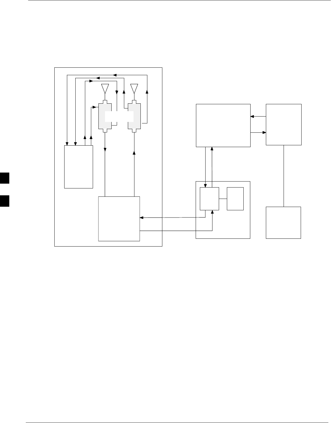
Optional BTS Equipment Identification 68P64115A19–4
Mar 2003
1X SC 4812T-MC BTS Hardware Installation - Software Release R2.16.1.x
CONTROLLED INTRODUCTION
4-6
RFDS Cabling to the BTS
This section of the manual will cover the basic cabling connection for
the SC 4812T–MC BTS frame. Figure 4-4 showns the connects from the
TX and RX BTS antennas to the CDMA RFDS unit.
Figure 4-4: RFDS (Block Diagram)
OMC–R
TTE
(SAGE)
CBSC
MDM AND LPAs
BTS
XC MM
CDMA
RFDS
MSC
DIRECTIONAL
COUPLERS
RX TX
FW00528
4

BTS Antenna Configuration
68P64115A19–4
Mar 2003 1X SC 4812T-MC BTS Hardware Installation - Software Release R2.16.1.x
CONTROLLED INTRODUCTION
4-7
BTS Antenna Configuration
Overview
This section provides detail on the antenna configurations supported by
the BTS, including:
S3 Sector
S6 Sector
4
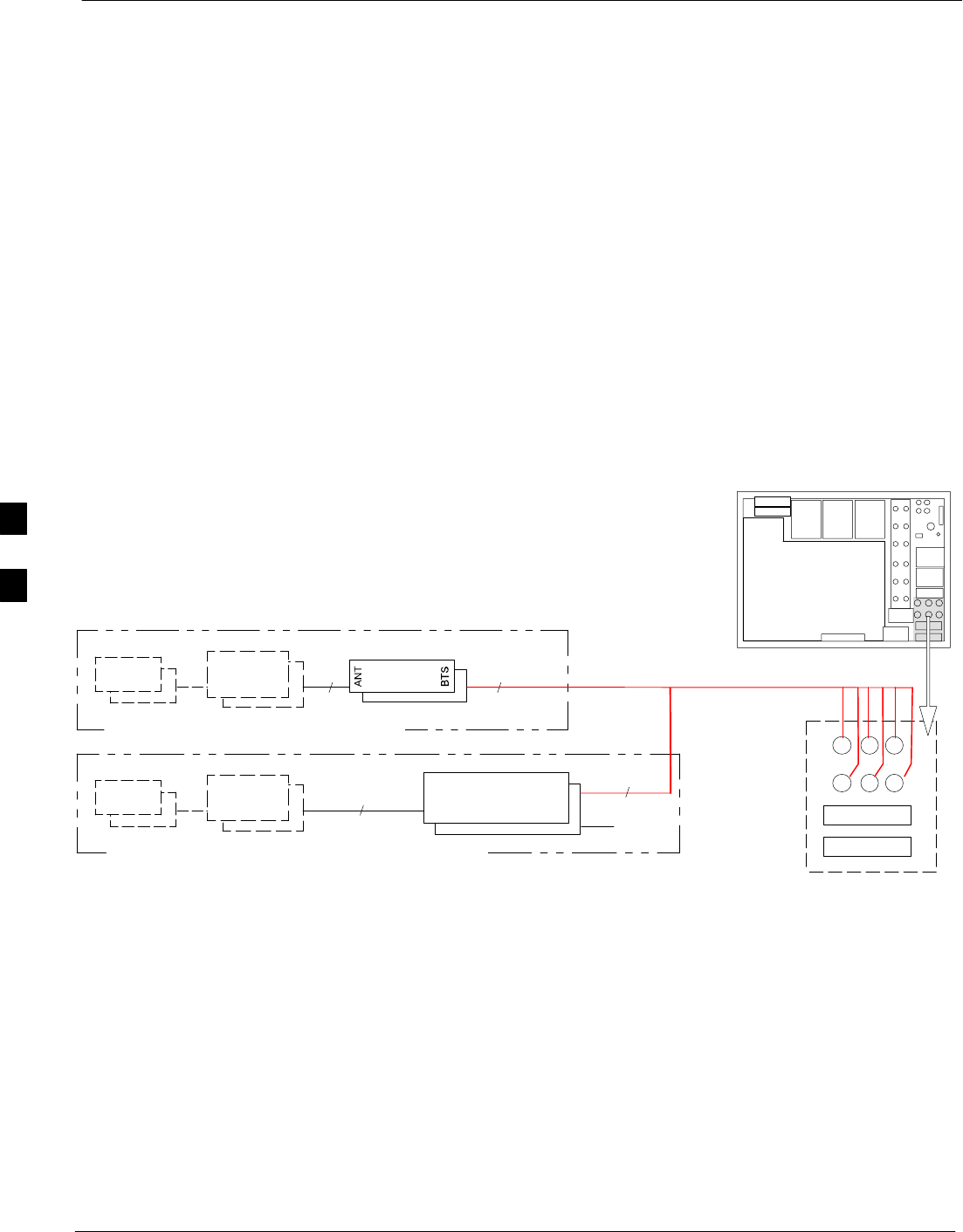
BTS 60 Degree Sector (6 Sector) Transmit Path Cabling 68P64115A19–4
Mar 2003
1X SC 4812T-MC BTS Hardware Installation - Software Release R2.16.1.x
CONTROLLED INTRODUCTION
4-8
BTS 60 Degree Sector (6 Sector) Transmit Path Cabling
Objective
The objective of this procedure is to install the BTS transmit path
cabling.
Cable Labels
The cable designations referenced in Table 4-2, provide the quantities
and descriptions of the cables required for the procedure.
Cabling Diagram
Figure 4-5 shows two types of configurations. Select the diagram that
depicts your site’s configuration. Table 4-5 describes the antenna cable
connection ports.
Figure 4-5: 60 Degree Sector (6 Sector) Transmit Path Cabling Details
TX OUT
LIGHTNING
ARRESTOR
ANTENNA
WITH OPTIONAL DIRECTIONAL COUPLER
DIRECTIONAL
COUPLER CARRIER 1 & 2
I/O PLATE
6
1..6
1..6
1..
6G
LIGHTNING
ARRESTOR
ANTENNA
6
1..6
1..6
1..
WITH OPTIONAL DUPLEXER DIRECTIONAL COUPLER
6
G
6
6
RX
NOTE: Unused TX ports on the DDC must be terminated.
DDC
ti-CDMA-WP-00048-v04-ildoc-ftw
123
456
789
10 11 12
4

BTS 60 Degree Sector (6 Sector) Transmit Path Cabling
68P64115A19–4
Mar 2003 1X SC 4812T-MC BTS Hardware Installation - Software Release R2.16.1.x
CONTROLLED INTRODUCTION
4-9
60 Degree Sector Configuration
Table 4-2 provides the Cable Run List for 60 degree sector transmit
paths.
Table 4-2: Cable Run List for 60 Degree Sector TX Configuration
Cable Cable Parts Connecting Lightning Arrestors To BTS TX Connectors
Gvia Directional Coupler via DDC BTS TX Ports
Quantity 12 18 TX1 to TX6
Procedure Install each cable by using the cable run list in Table 4-2, the cabling
diagram in Figure 4-5, and the procedure in Table 4-3. Each cable is
installed the same way.
Table 4-3: Installing the 60 Degree Sector TX Path Cables
Step Action
1Attach the connector–equipped end of the cables to the BTS TX connectors.
2Route the cables to the DCs or DDCs.
3Cut the cables to length and label them accordingly. Install connectors on the cables and attach the
cables to the DDCs TX connector or Directional Couplers BTS connectors.
4Attach the connector-equipped end of additional cables to the DDCs or Directional Couplers ANT
connectors.
5Route the cables to the lightning arrestors.
4
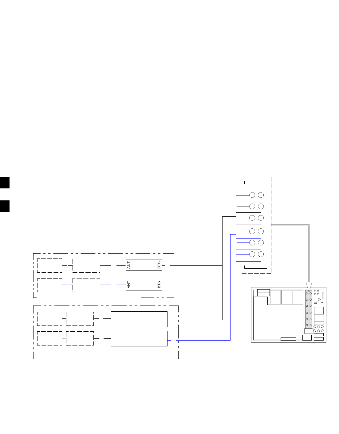
BTS 60 Degree Sector (6 Sector) Receive Path Cabling 68P64115A19–4
Mar 2003
1X SC 4812T-MC BTS Hardware Installation - Software Release R2.16.1.x
CONTROLLED INTRODUCTION
4-10
BTS 60 Degree Sector (6 Sector) Receive Path Cabling
Objective
The objective of this procedure is to install the BTS transmit path
cabling.
Cable Labels
The cable designations are referenced in Table 2-1 the “Overall Cabling
Diagrams and Description” area. Table 4-4, and Table 4-5 provide the
quantities and descriptions of the cables required for this procedure.
Cabling Diagram
Figure 4-6 shows two types of configurations. Select the diagram that
depicts your site’s configuration. Table 4-5 describes the antenna cable
connection ports.
Figure 4-6: 60 Degree Sector (6 Sector) Receive Path Cabling Details
LIGHTNING
ARRESTORS
WITH OPTIONAL DIRECTIONAL COUPLER
WITH OPTIONAL DUPLEXER DIRECTIONAL COUPLER
DIRECTIONAL
COUPLER
LIGHTNING
ARRESTORS
LIGHTNING
ARRESTORS
DIRECTIONAL
COUPLER
LIGHTNING
ARRESTORS
G
G
G
G
G
G
1A, 2A, 3A
4A, 5A, 6A
MAIN
DIV
1B, 2B, 3B
4B, 5B, 6B
1A, 2A, 3A
4A, 5A, 6A
MAIN
DIV
1B, 2B, 3B
4B, 5B, 6B
DDC
DDC
ti-CDMA-WP-00049-v04-ildoc-ftw
3A
2A
6A
5A
4A
3B
2B
1B
6B
5B
4B
1A
RX
RX
I/O PLATE
G
G
1B, 2B, 3B, 4B, 5B, 6B
1A, 2A, 3A, 4A, 5A, 6A
1A, 2A, 3A, 4A, 5A, 6A
1B, 2B, 3B, 4B, 5B, 6B
TX
TX
4

BTS 60 Degree Sector (6 Sector) Receive Path Cabling
68P64115A19–4
Mar 2003 1X SC 4812T-MC BTS Hardware Installation - Software Release R2.16.1.x
CONTROLLED INTRODUCTION
4-11
Table 4-4: Cables Needed for 120 Degree Sector Receive Path
Cable Qty. Part Number Description
G(see Table 4-11) CGDS2212602 15 ft. Jumper Cable, N/M–N/M.
Table 4-5: Cable Run List for 60 Degree Sector Receive Path Cabling
Cable Cable path connecting Lightning Arrestors to BTS RX connectors RX Ports Used
Gvia Directional Coupler via DDC RX 1A–6A
Quantity 24 36
RX 1A 6A
RX 1B–6B
Procedure
Install each cable by using the cable run list in Table 4-11, the cabling
diagram in Figure 4-8, and the procedure in Table 4-12. Each cable is
installed the same way.
Table 4-6: Installing the 60 Degree Sector Receive Path Cables
Step Action
1Attach the connector–equipped end of the cables to the BTS RX connectors.
2Route the cables to the DDCs.
3Cut the cables to length and label them accordingly. Install connectors on the cables, and attach the
cables to the DDCs RX connector or Directional Couplers BTS connectors.
4Attach the connector-equipped end of additional cables to the DDCs or Directional Couplers ANT
connectors.
5Route the cables to the lightning arrestors.
6Cut the cables to length and label them accordingly. Install connectors on the cables.
4
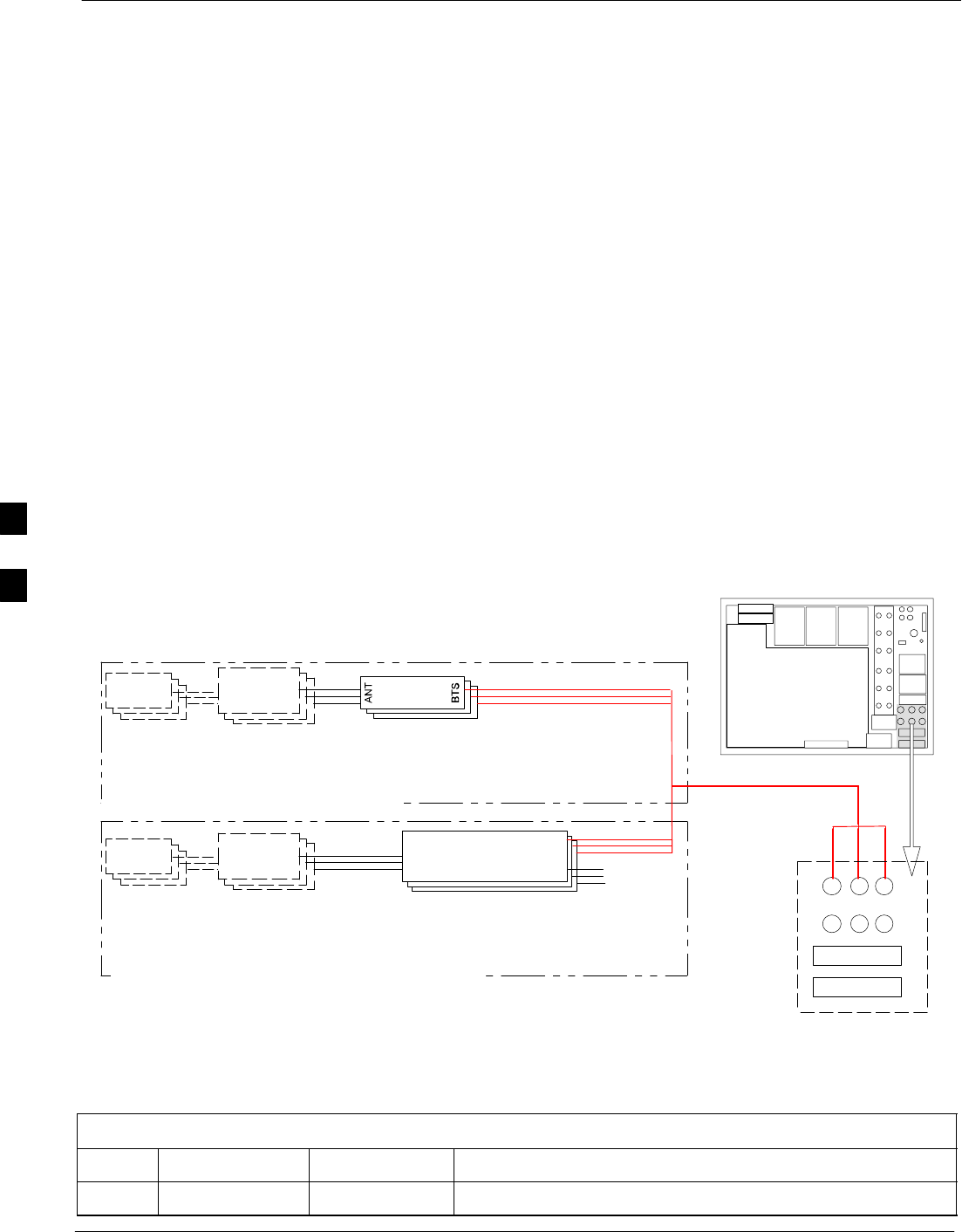
BTS 120 Degree Sector (3 Sector) Transmit Path Cabling 68P64115A19–4
Mar 2003
1X SC 4812T-MC BTS Hardware Installation - Software Release R2.16.1.x
CONTROLLED INTRODUCTION
4-12
BTS 120 Degree Sector (3 Sector) Transmit Path Cabling
Objective
The objective of this procedure is to install the 120 degree BTS transmit
path cabling.
Cable Labels
The cable designations are referenced to Table 2-1 in the “Cabling
Diagrams and Description” area. Table 4-7 and Table 4-8 provide the
quantities and descriptions of the cables required for this procedure.
Cabling Diagram
Figure 4-7 shows two types of configurations; select the diagram that
depicts your site’s configuration. Table 4-7 and Table 4-8, on page 4-13,
describes the antenna cable connection ports.
Figure 4-7: 120 Degree Sector (3 Sector) Transmit Path Cabling Details
LIGHTNING
ARRESTOR
ANTENNA
NOTE: Unused TX ports on the DDC must be terminated with 50
ohm loads (Part #58–82106P01) which are included with
the duplexer mounting hardware kit (STLN4001A).
WITH OPTIONAL DIRECTIONAL COUPLER
WITH OPTIONAL DUPLEXER DIRECTIONAL COUPLER
DIRECTIONAL
COUPLER
G
G
G
LIGHTNING
ARRESTOR
ANTENNA
G
G
G
DDCDDC
ti-CDMA-WP-00050-v04-ildoc-ftw
TX OUT
123
456
789
10 11 12
RX
I/O PLATE
CARRIER 1–4
Table 4-7: Cables Needed for 120 Degree Sector Transmit Path
Cable Qty. Part Number Description
G(see Table 4-8) CGDS2212602 15 ft Jumper Cable, N/M–N/M.
4

BTS 120 Degree Sector (3 Sector) Transmit Path Cabling
68P64115A19–4
Mar 2003 1X SC 4812T-MC BTS Hardware Installation - Software Release R2.16.1.x
CONTROLLED INTRODUCTION
4-13
Table 4-8: Cable Run List for 120 Degree Sector Configuration
Cable Cable Parts Connecting Lightning Arrestors To BTS TX Connectors
Gvia Directional Coupler via DDC BTS TX Ports
Quantity
6 9 TX1, TX2, TX3 (1)
Q
uant
i
ty 12 12 TX1, TX2, TX3
Procedure Install each cable by using the cable run list in Table 4-8, the cabling
diagram in Figure 4-7, and the procedure in Table 4-9. Each cable is
installed the same way.
Table 4-9: Installing the 120 Degree Sector TX Path Cables
Step Action
1Attach the connector–equipped end of the cables to the BTS TX connectors.
2Route the cables to the DCs or DDCs.
3Cut the cables to length and label them accordingly. Install connectors on the cables and attach the
cables to the DDCs TX connector or Directional Couplers BTS connectors.
4Attach the connector–equipped end of additional cables to the DDCs ANT connectors.
5Route the cables to the lightning arrestors.
6Cut the cables to length and label them accordingly. Install connectors on the cables and attach the
cables to the Lightning Arrestors.
4

BTS 120 Degree Sector (3 Sector) Receive Path Cabling 68P64115A19–4
Mar 2003
1X SC 4812T-MC BTS Hardware Installation - Software Release R2.16.1.x
CONTROLLED INTRODUCTION
4-14
BTS 120 Degree Sector (3 Sector) Receive Path Cabling
Objective
The objective of this procedure is to install the BTS receive path cabling.
120-degree sector receive path cabling is used for CDMA and analog
systems.
Cable Labels
The cable designations are referenced to Table 2-1 in the “Cabling
Diagrams and Description” area. Table 4-10 and Table 4-11 provide the
quantities and descriptions of the cables required for this procedure.
Table 4-10: Cables Needed for 120 Degree Sector Receive Path
Cable Qty. Part Number Description
G(see Table 4-11) CGDS2212602 15 ft. Jumper Cable, N/M–N/M.
Cabling Diagram
Figure 4-8 shows two types of configurations; select the diagram that
depicts your site’s configuration. Table 4-11 describes the antenna cable
connection ports.
Table 4-11: Cable Run List for 120 Degree Sector Receive Path Cabling
Cable Cable path connecting Lightning Arrestors
to BTS RX connectors RX Antenna Ports
Gvia Directional Coupler via DDC RX 1A
RX 2A
RX 3A
Quantity 12 12
RX 3A
RX 1B
RX 2B
RX 3B
4
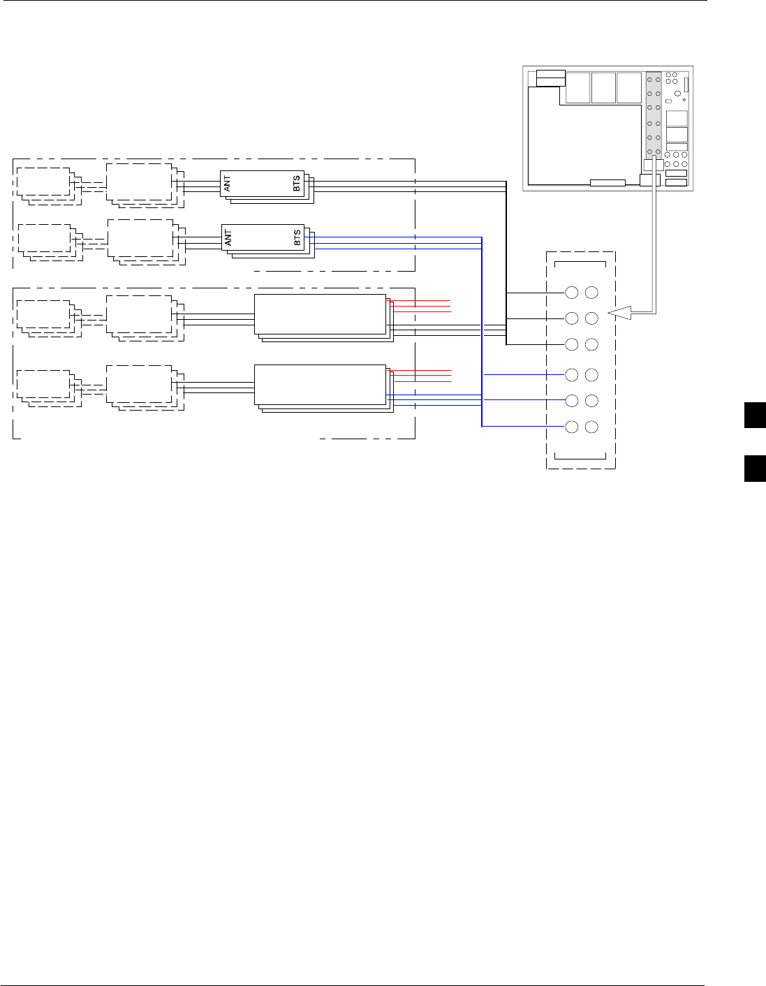
BTS 120 Degree Sector (3 Sector) Receive Path Cabling
68P64115A19–4
Mar 2003 1X SC 4812T-MC BTS Hardware Installation - Software Release R2.16.1.x
CONTROLLED INTRODUCTION
4-15
Figure 4-8: 120 Degree Sector (3 Sector) Receive Path Cabling Details
LIGHTNING
ARRESTOR
ANTENNA
WITH OPTIONAL DIRECTIONAL COUPLER
WITH OPTIONAL DUPLEXER DIRECTIONAL COUPLER
DIRECTIONAL
COUPLER
DIRECTIONAL
COUPLER
G
LIGHTNING
ARRESTOR
ANTENNA
G
G
LIGHTNING
ARRESTOR
ANTENNA
G
LIGHTNING
ARRESTOR
ANTENNA
G
G
G
G
DDCDDC
DDC
ti-CDMA-WP-00206-v01-ildoc-ftw–REF
3A
2A
6A
5A
4A
3B
2B
1B
6B
5B
4B
1A
RX
RX
TX
TX
I/O PLATE
Note: For single frame terminate all unused TX ports on DDCs
4

BTS 120 Degree Sector (3 Sector) Receive Path Cabling 68P64115A19–4
Mar 2003
1X SC 4812T-MC BTS Hardware Installation - Software Release R2.16.1.x
CONTROLLED INTRODUCTION
4-16
Cabling Procedure
Install each cable by referring to the cable run list in Table 4-11, the
cabling diagram in Figure 4-8, and the procedure in Table 4-12. Each
cable is installed the same way.
Table 4-12: Installing the 120 Degree Sector Receive Path Cables
Step Action
1Attach the connector-equipped end of the cables to the BTS RX connectors.
2Use the following step to connect the DDCs to the antenna system.
– Cut the cables to length and label them accordingly. Install connectors on the cables and attach
the cables to the DDCs RX connector or BTS connectors.
– Attach the connector-equipped end of additional cables to the DDCs’ ANT connectors.
3Route the cables to the lightning arrestors.
4

3 Sector Non–Duplexed Cabling
68P64115A19–4
Mar 2003 1X SC 4812T-MC BTS Hardware Installation - Software Release R2.16.1.x
CONTROLLED INTRODUCTION
4-17
3 Sector Non–Duplexed Cabling
Objective
The objective of this procedure is to cable an external CDMA RFDS into
a 3-Sector Non-Duplexed BTS. This configuration covers the SC
4812T–MC BTS.
Cabling Diagram
Figure 4-9 shows the cabling from an RFDS to a 3-Sector Non-Duplexed
BTS configuration without regard to BTS type or band. Table 4-13 lists
the ports for the Directional Couplers and RFDS, and instructions for
installing the RF cables are shown in Table 4-14.
4
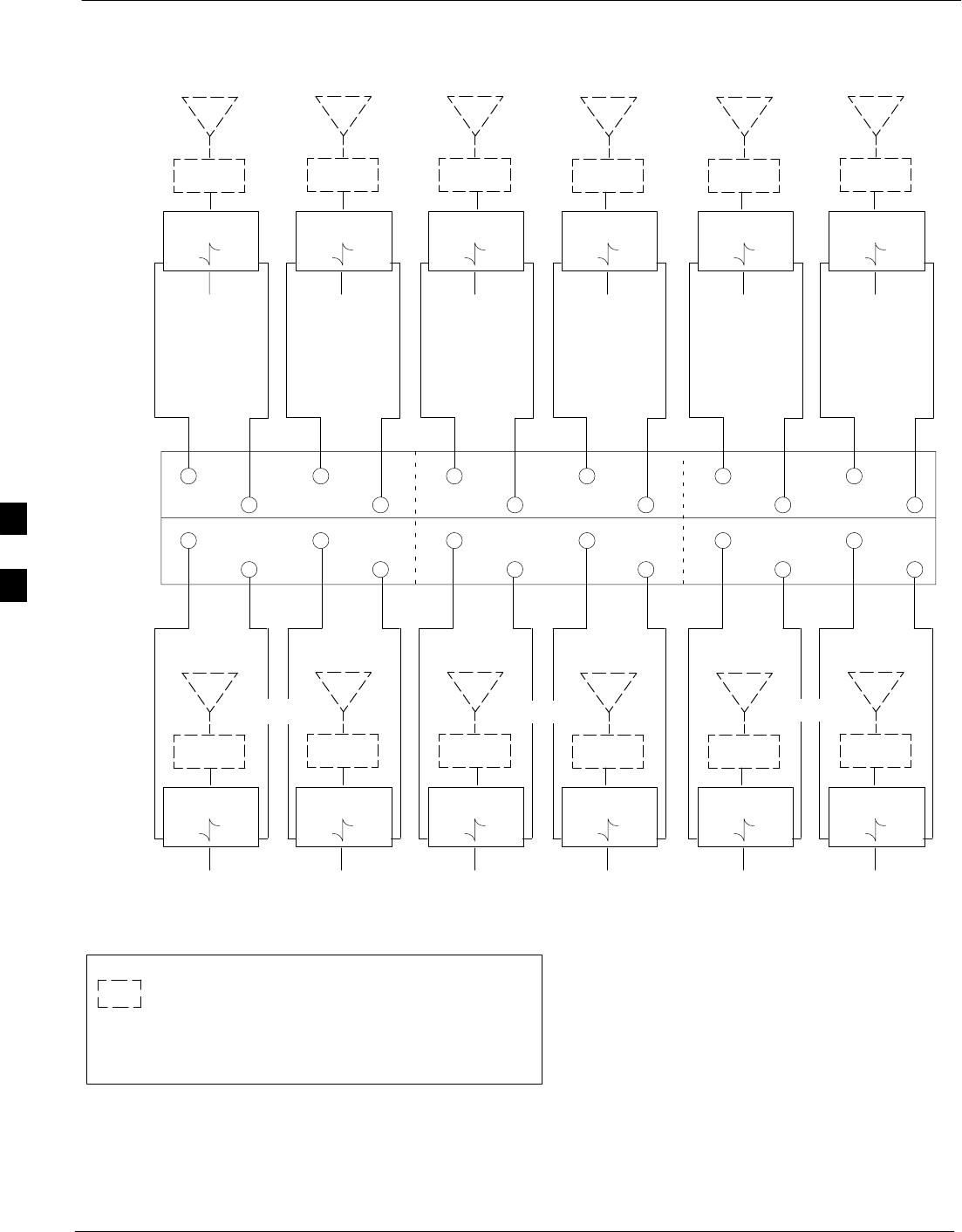
3 Sector Non–Duplexed Cabling 68P64115A19–4
Mar 2003
1X SC 4812T-MC BTS Hardware Installation - Software Release R2.16.1.x
CONTROLLED INTRODUCTION
4-18
ASU2
ASU1
DIRECTIONAL
COUPLER
FWD REV
LIGHTNING
ARRESTOR
ANT
123456
1234 5 6
RX Primary
DIRECTIONAL
COUPLER
FWD REV
LIGHTNING
ARRESTOR
ANT
DIRECTIONAL
COUPLER
FWD REV
LIGHTNING
ARRESTOR
ANT
DIRECTIONAL
COUPLER
FWD REV
LIGHTNING
ARRESTOR
ANT
DIRECTIONAL
COUPLER
FWD REV
LIGHTNING
ARRESTOR
ANT
DIRECTIONAL
COUPLER
FWD REV
LIGHTNING
ARRESTOR
ANT
FWD
REFL
TO BTS
Sector 1
RX Primary
Figure 4-9: 3-Sector Non–Duplexed Cabling Configurations
FWD
REFL
TO BTS
Sector 1
RX Diversity
TO BTS
Sector 2
RX Primary
TO BTS
Sector 2
RX Diversity
TO BTS
Sector 3
RX Primary
TO BTS
Sector 3
RX Diversity
123456
1234 5 6
RX Diversity RX Primary RX Diversity RX Primary RX Diversity
DIRECTIONAL
COUPLER
FWD REV
LIGHTNING
ARRESTOR
ANT
TX1
DIRECTIONAL
COUPLER
FWD REV
LIGHTNING
ARRESTOR
ANT
DIRECTIONAL
COUPLER
FWD REV
LIGHTNING
ARRESTOR
ANT
DIRECTIONAL
COUPLER
FWD REV
LIGHTNING
ARRESTOR
ANT
DIRECTIONAL
COUPLER
FWD REV
LIGHTNING
ARRESTOR
ANT
DIRECTIONAL
COUPLER
FWD REV
LIGHTNING
ARRESTOR
ANT
TO BTS
Sector 1
TX1
TO BTS
Sector 1
TX2*
TO BTS
Sector 2
TX1
TO BTS
Sector 2
TX2*
TO BTS
Sector 2
TX1
TO BTS
Sector 3
TX2*
TX2* TX1 TX2* TX1 TX2*
SECTOR 1 SECTOR 2 SECTOR 3
SECTOR 1 SECTOR 2 SECTOR 3
* TX2 – FOR SINGLE FRAME UNUSED TX PORTS ON THE
DUPLEXER MUST BE TERMINATED WITH A 50 OHM LOAD.
FOR EXPANSION CONNECT CABLES HERE
LEGEND:
= EXISTING EQUIPMENT
4

3 Sector Non–Duplexed Cabling
68P64115A19–4
Mar 2003 1X SC 4812T-MC BTS Hardware Installation - Software Release R2.16.1.x
CONTROLLED INTRODUCTION
4-19
Table 4-13: 3-Sector Non-Duplexed Directional Coupler to RFDS Cabling Table
Directional Coupler Port (RX) Cobra RFDS Port Stand-Alone RFDS Port
Sector 1 RX Pri FWD ASU1–1 FWD ASU1–1
Sector 1 RX Pri REF ASU1–1 REF ASU1–8
Sector 1 RX Div FWD ASU1–2 FWD ASU1–2
Sector 1 RX Div REF ASU1–2 REV ASU1–9
Sector 2 RX Pri FWD ASU1–3 FWD ASU1–3
Sector 2 RX Pri REF ASU1–3 REV ASU1–10
Sector 2 RX Div FWD ASU1–4 FWD ASU1–4
Sector 2 RX Div REF ASU1–4 REV ASU1–11
Sector 3 RX Pri FWD ASU1–5 FWD ASU1–5
Sector 3 RX Pri REF ASU1–5 REF ASU1–12
Sector 3 RX Div FWD ASU1–6 FWD ASU1–6
Sector 3 RX Div REF ASU1–6 REF ASU1–13
Directional Coupler Port (TX) Cobra RFDS Port Stand-Alone RFDS Port
Sector 1 TX1 FWD ASU2–1 FWD ASU2–1
Sector 1 TX1 REF ASU2–1 REF ASU2–8
Sector 1 TX2 FWD ASU2–2 FWD ASU2–2
Sector 1 TX2 REF ASU2–2 REF ASU2–9
Sector 2 TX1 FWD ASU2–3 FWD ASU2–3
Sector 2 TX1 REF ASU2–3 REF ASU2–10
Sector 2 TX2 FWD ASU2–4 FWD ASU2–4
Sector 2 TX2 REF ASU2–4 REF ASU2–11
Sector 3 TX1 FWD ASU2–5 FWD ASU2–5
Sector 3 TX1 REF ASU2–5 REF ASU2–12
Sector 3 TX2 FWD ASU2–6 FWD ASU2–6
Sector 3 TX2 REF ASU2–6 REF ASU2–13
Table 4-14: Installing RF Cables in a 3-Sector Non-Duplexed System
Step Action
1Attach the SMA-type connector cables to the Directional Couplers.
2Route the cables to the RFDS.
3Attach the cables to the RFDS according to Figure 4-9, and Table 4-13.
4Torque all SMA-type RF connectors to 8 in-lb.
4
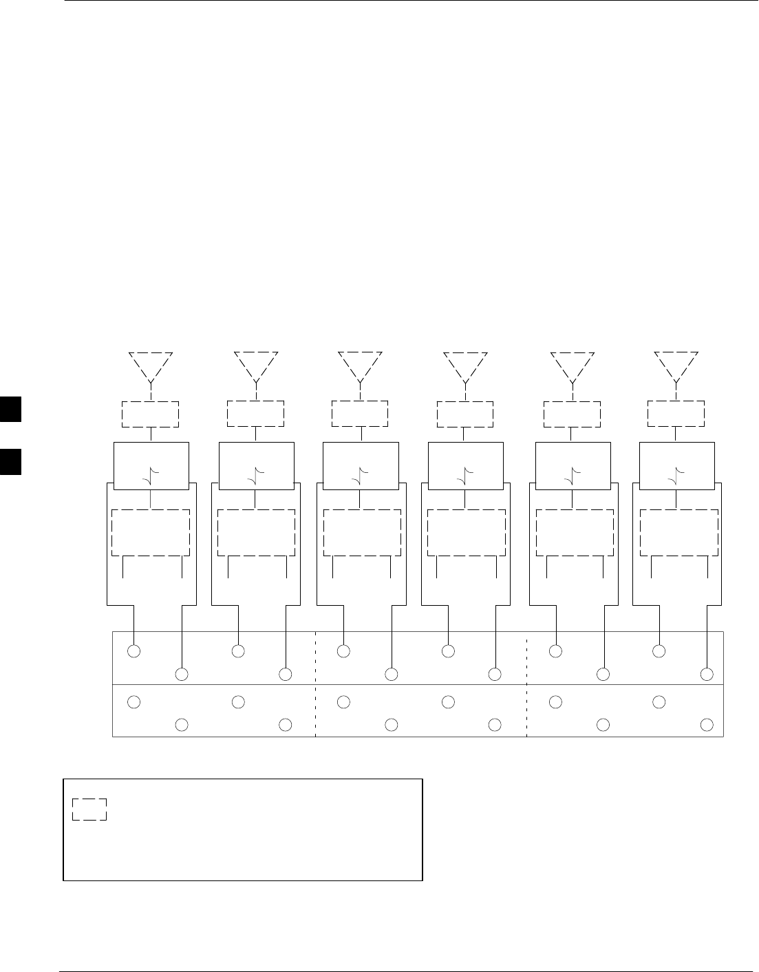
3 Sector Duplexed 68P64115A19–4
Mar 2003
1X SC 4812T-MC BTS Hardware Installation - Software Release R2.16.1.x
CONTROLLED INTRODUCTION
4-20
3 Sector Duplexed
Objective
The objective of this procedure is to install an external CDMA RFDS
into a 3-Sector Duplexed site. This configuration covers all indoor BTS
types.
Cabling Diagram
Figure 4-10 shows the cabling from an RFDS to a 3-Sector Duplexed
BTS configuration without regard to BTS type or band. Table 4-15 lists
the ports for the Directional Couplers and RFDS, and instructions for
installing the RF cables are shown in Table 4-16.
ASU2
ASU1
DIRECTIONAL
COUPLER
FWD REV
LIGHTNING
ARRESTOR
ANT
123456
1234 5 6
RX Pri / TX1
DIRECTIONAL
COUPLER
FWD REV
LIGHTNING
ARRESTOR
ANT
DIRECTIONAL
COUPLER
FWD REV
LIGHTNING
ARRESTOR
ANT
DIRECTIONAL
COUPLER
FWD REV
LIGHTNING
ARRESTOR
ANT
DIRECTIONAL
COUPLER
FWD REV
LIGHTNING
ARRESTOR
ANT
DIRECTIONAL
COUPLER
FWD REV
LIGHTNING
ARRESTOR
ANT
FWD
REFL
TO BTS
Sector 1
TX1 RX Pri
Figure 4-10: 3–Sector Duplexed Cabling Configurations
FWD
REFL
TO BTS
Sector 1
TX2 * RX Div
TO BTS
Sector 2
TX1 RX Pri
TO BTS
Sector 2
TX2* RX Div
TO BTS
Sector 3
TX1 RX Pri
TO BTS
Sector 3
TX2* RX Div
123456
1234 5 6
RX Div / TX2* RX Pri / TX1 RX Div / TX2* RX Pri / TX1 RX Div / TX2*
SECTOR 1 SECTOR 2 SECTOR 3
* TX2 – FOR SINGLE FRAME UNUSED TX PORTS ON THE
DUPLEXER MUST BE TERMINATED WITH A 50 OHM LOAD.
FOR EXPANSION CONNECT CABLES HERE
LEGEND:
= EXISTING EQUIPMENT
DUPLEXER
ANT
TX RX
DUPLEXER
ANT
TX RX
DUPLEXER
ANT
TX RX
DUPLEXER
ANT
TX RX
DUPLEXER
ANT
TX RX
DUPLEXER
ANT
TX RX
4

3 Sector Duplexed
68P64115A19–4
Mar 2003 1X SC 4812T-MC BTS Hardware Installation - Software Release R2.16.1.x
CONTROLLED INTRODUCTION
4-21
Table 4-15: 3-Sector Duplexed Directional Coupler to RFDS Cabling Table
Directional Coupler Port Cobra RFDS Port Stand-Alone RFDS Port
Sector 1 RX Pri/TX1 Fwd ASU1–1 FWD ASU1–1
Sector 1 RX Pri/TX1 Ref ASU1–1 REF ASU1–8
Sector 1 RX Div/TX2 Fwd ASU1–2 FWD ASU1–2
Sector 1 RX Div/TX2 Ref ASU1–2 REV ASU1–9
Sector 2 RX Pri/TX1 Fwd ASU1–3 FWD ASU1–3
Sector 2 RX Pri/TX1 Ref ASU1–3 REV ASU1–10
Sector 2 RX Div/TX2 Fwd ASU1–4 FWD ASU1–4
Sector 2 RX Div/TX2 Ref ASU1–4 REV ASU1–11
Sector 3 RX Pri/TX1 Fwd ASU1–5 FWD ASU1–5
Sector 3 RX Pri/TX1 Ref ASU1–5 REF ASU1–12
Sector 3 RX Div/TX2 Fwd ASU1–6 FWD ASU1–6
Sector 3 RX Div/TX2 Ref ASU1–6 REF ASU1–13
Table 4-16: Installing RF Cables in a 3-Sector Duplexed System
Step Action
1Attach the SMA-type connector cables to the Directional Couplers.
2Route the cables to the RFDS.
3Attach the cables to the RFDS according to Figure 4-10, and Table 4-15.
4Torque all SMA-type RF connectors to 8 in-lb.
4

6 Sector Duplexed 68P64115A19–4
Mar 2003
1X SC 4812T-MC BTS Hardware Installation - Software Release R2.16.1.x
CONTROLLED INTRODUCTION
4-22
6 Sector Duplexed
Objective
The objective of this procedure is to cable an external CDMA RFDS into
a 6-Sector Duplexed BTS system. This configuration covers the
SC 4812T BTS.
Cabling Diagram
Figure 4-11 shows the cabling from an RFDS to a 6–Sector Duplexed
BTS configuration without regard to BTS type or band. Table 4-17 lists
the ports for the Directional Couplers and RFDS, and instructions for
installing the RF cables are shown in Table 4-18.
4
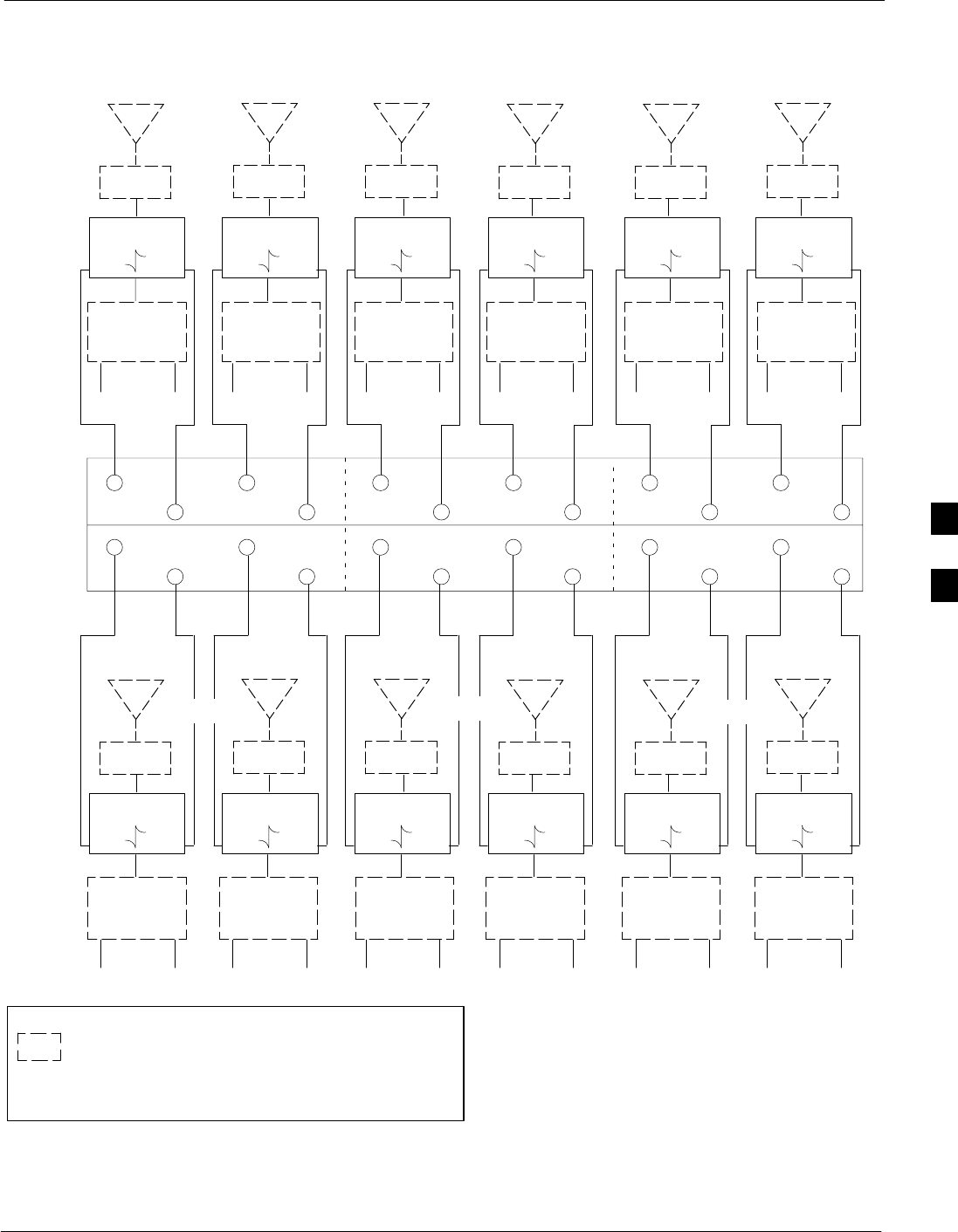
6 Sector Duplexed
68P64115A19–4
Mar 2003 1X SC 4812T-MC BTS Hardware Installation - Software Release R2.16.1.x
CONTROLLED INTRODUCTION
4-23
ASU2
ASU1
DIRECTIONAL
COUPLER
FWD REV
LIGHTNING
ARRESTOR
ANT
123456
1234 5 6
RX Pri / TX1
DIRECTIONAL
COUPLER
FWD REV
LIGHTNING
ARRESTOR
ANT
DIRECTIONAL
COUPLER
FWD REV
LIGHTNING
ARRESTOR
ANT
DIRECTIONAL
COUPLER
FWD REV
LIGHTNING
ARRESTOR
ANT
DIRECTIONAL
COUPLER
FWD REV
LIGHTNING
ARRESTOR
ANT
DIRECTIONAL
COUPLER
FWD REV
LIGHTNING
ARRESTOR
ANT
FWD
REFL
TO BTS
Sector 1
TX1 RX Pri
Figure 4-11: 6-Sector Duplexed Cabling Configurations
FWD
REFL
TO BTS
Sector 1
TX* RX Div
TO BTS
Sector 2
TX1 RX Pri
TO BTS
Sector 2
TX* RX Div
TO BTS
Sector 3
TX1 RX Pri
TO BTS
Sector 3
TX* RX Div
123456
1234 5 6
RX Div / RX Pri / TX2 RX Div / RX Pri / TX3 RX Div /
DIRECTIONAL
COUPLER
FWD REV
LIGHTNING
ARRESTOR
ANT
RX Pri / TX4
DIRECTIONAL
COUPLER
FWD REV
LIGHTNING
ARRESTOR
ANT
DIRECTIONAL
COUPLER
FWD REV
LIGHTNING
ARRESTOR
ANT
DIRECTIONAL
COUPLER
FWD REV
LIGHTNING
ARRESTOR
ANT
DIRECTIONAL
COUPLER
FWD REV
LIGHTNING
ARRESTOR
ANT
DIRECTIONAL
COUPLER
FWD REV
LIGHTNING
ARRESTOR
ANT
TO BTS
Sector 4
TX1 RX Pri
TO BTS
Sector 4
TX* RX Div
TO BTS
Sector 5
TX1 RX Pri
TO BTS
Sector 5
TX* RX Div
TO BTS
Sector 6
TX1 RX Pri
TO BTS
Sector 6
TX* RX Div
RX Div / RX Pri / TX5 RX Div / RX Pri / TX6 RX Div / TX2*
DUPLEXER
ANT
TX RX
DUPLEXER
ANT
TX RX
DUPLEXER
ANT
TX RX
DUPLEXER
ANT
TX RX
DUPLEXER
ANT
TX RX
DUPLEXER
ANT
TX RX
DUPLEXER
ANT
TX RX
DUPLEXER
ANT
TX RX
DUPLEXER
ANT
TX RX
DUPLEXER
ANT
TX RX
DUPLEXER
ANT
TX RX
DUPLEXER
ANT
TX RX
SECTOR 1 SECTOR 2 SECTOR 3
SECTOR 4 SECTOR 5 SECTOR 6
TX* – FOR SINGLE FRAME UNUSED TX PORTS ON THE
DUPLEXER MUST BE TERMINATED WITH A 50 OHM LOAD.
FOR EXPANSION CONNECT CABLES HERE
LEGEND:
= EXISTING EQUIPMENT
4

6 Sector Duplexed 68P64115A19–4
Mar 2003
1X SC 4812T-MC BTS Hardware Installation - Software Release R2.16.1.x
CONTROLLED INTRODUCTION
4-24
Table 4-17: 6-Sector Duplexed Directional Coupler to RFDS Cabling Table
Directional Coupler Port Cobra RFDS Port Stand-Alone RFDS Port
Sector 1 RX Pri/TX1 Fwd ASU1–1 FWD ASU1–1
Sector 1 RX Pri/TX1 Ref ASU1–1 REF ASU1–8
Sector 1 RX Div/TX2 Fwd ASU1–2 FWD ASU1–2
Sector 1 RX Div/TX2 Ref ASU1–2 REV ASU1–9
Sector 2 RX Pri/TX1 Fwd ASU1–3 FWD ASU1–3
Sector 2 RX Pri/TX1 Ref ASU1–3 REV ASU1–10
Sector 2 RX Div/TX2 Fwd ASU1–4 FWD ASU1–4
Sector 2 RX Div/TX2 Ref ASU1–4 REV ASU1–11
Sector 3 RX Pri/TX1 Fwd ASU1–5 FWD ASU1–5
Sector 3 RX Pri/TX1 Ref ASU1–5 REF ASU1–12
Sector 3 RX Div/TX2 Fwd ASU1–6 FWD ASU1–6
Sector 3 RX Div/TX2 Ref ASU1–6 REF ASU1–13
Sector 4 RX Pri/TX1 Fwd ASU2–1 FWD ASU2–1
Sector 4 RX Pri/TX1 Ref ASU2–1 REF ASU2–8
Sector 4 RX Div/TX2 Fwd ASU2–2 FWD ASU2–2
Sector 4 RX Div/TX2 Ref ASU2–2 REF ASU2–9
Sector 5 RX Pri/TX1 Fwd ASU2–3 FWD ASU2–3
Sector 5 RX Pri/TX1 Ref ASU2–3 REF ASU2–10
Sector 5 RX Div/TX2 Fwd ASU2–4 FWD ASU2–4
Sector 5 RX Div/TX2 Ref ASU2–4 REF ASU2–11
Sector 6 RX Pri/TX1 Fwd ASU2–5 FWD ASU2–5
Sector 6 RX Pri/TX1 Ref ASU2–5 REF ASU2–12
Sector 6 RX Div/TX2 Fwd ASU2–6 FWD ASU2–6
Sector 6 RX Div/TX2 Ref ASU2–6 REF ASU2–13
Table 4-18: Installing RF Cables in a 6-Sector Duplexed System
Step Action
1Attach the SMA-type connector cables to the Directional Couplers.
2Route the cables to the RFDS.
3Attach the cables to the RFDS according to Figure 4-11, and Table 4-17.
4Torque all SMA-type RF connectors to 8 in-lb.
4

Mar 2003 1X SC 4812T-MC BTS Hardware Installation - Software Release R2.16.1.x
CONTROLLED INTRODUCTION
5-1
Chapter 5
What’s Next and Site Cleanup
5

What’s Next 68P64115A19–4
Mar 2003
1X SC 4812T-MC BTS Hardware Installation - Software Release R2.16.1.x
CONTROLLED INTRODUCTION
5-2
What’s Next
Introduction
Before beginning the Optimization procedure, there are two things left to
do.
SClean up the site.
SFill out the installation completion checklist.
Clean Up the Site
Clean up the site by following the information given in the “Site
Cleanup” area in this chapter.
Fill Out Checklist
After the site is cleaned up, fill out the installation completion checklist.
This checklist is located in the “Installation Completion Checklist” area
of this chapter.
Optimize the System
Optimize the system by following the procedures given in the
appropriate optimization manual for your site.
The hardware installation manual does not include card placement and
turning on power. These procedures are covered in the appropriate
optimization manual.
5

Site Cleanup
68P64115A19–4
Mar 2003 1X SC 4812T-MC BTS Hardware Installation - Software Release R2.16.1.x
CONTROLLED INTRODUCTION
5-3
Site Cleanup
Remove Protective Covering
Remove any cardboard from the walls used to protect the walls.
Remove any antistatic plastic or cloth sheeting used to cover the
equipment.
Lighting Fixtures
Remove any masking tape from the fluorescent light fixtures.
Tools
Place all hand and power tools in the installation tool kit or other
appropriate place. Note any tools needing replacement, cleaning, or
adjustment.
Materials
Place any leftover materials in a location specified by the site manager.
Remove Debris
Remove any packing material.
Ensure that all scrap materials have been removed from any tables or
stands.
Clean/sweep the floor. Ensure all chalk line marks have been removed.
Environment
Check that all covers, frame doors, and fan housings are in place.
Confirm all power connections are tight.
Organize any items (manuals, materials, etc.) left on site and place them
in a safe location specified by the site manager.
5

Installation Completion Checklist 68P64115A19–4
Mar 2003
1X SC 4812T-MC BTS Hardware Installation - Software Release R2.16.1.x
CONTROLLED INTRODUCTION
5-4
Installation Completion Checklist
Directions
Fill out the installation completion checklist and make any necessary
copies. You may copy this check sheet as needed.
Installation Completion Checklist
Date Hardware Installation Completed:
Site:
Master BTS Frame Serial Number:
Expansion BTS Frame Serial Number(s):
Checklist Completed By:
Checklist Reviewed By:
Table 5-1: Installation Completion Checklist
Status No. Item Notes
1Frames are bolted down.
2DC power cabling completed.
3Each frame has its own earth ground.
4RX RF cables installed.
5TX RF cables installed.
6LAN cables installed.
7Span line cables installed.
8Alarm cables installed.
9Modem cables installed.
10 GPS antenna installed.
11 LFR antenna installed (if required).
12 GPS antenna cabling installed.
13 LFR antenna cabling installed (if required).
14 RF connectors are tight.
15 Power connections are tight.
16 RF cables are labeled the same at both ends.
17 Data cables labeled at both ends.
18 Remote GPS (if required).
19 Remote GPS cables (if required).
20 Ethernet LAN cables and terminators
installed.
. . . continued on next page
5

Installation Completion Checklist
68P64115A19–4
Mar 2003 1X SC 4812T-MC BTS Hardware Installation - Software Release R2.16.1.x
CONTROLLED INTRODUCTION
5-5
Table 5-1: Installation Completion Checklist
Status NotesItemNo.
21 All cables dressed and tied.
22 Cross-connect completed (if applicable).
23 Installation and site specific manuals at site.
24 Cable racks properly grounded.
25 Static wrist straps are present.
26 Site cleaned, swept, and trash removed.
27 Any deficiencies reported to the appropriate
people.
28 Correct polarity has been maintained from the
DC power source to the frame.
29 Power has not been applied to any frame.
5

Installation Completion Checklist 68P64115A19–4
Mar 2003
1X SC 4812T-MC BTS Hardware Installation - Software Release R2.16.1.x
CONTROLLED INTRODUCTION
5-6
Notes
5

Mar 2003 1X SC 4812T-MC BTS Hardware Installation - Software Release R2.16.1.x
CONTROLLED INTRODUCTION
A-1
Appendix A
Carrier Add Instructions
A

Carrier Add Instructions 68P64115A19–4
Mar 2003
1X SC 4812T-MC BTS Hardware Installation - Software Release R2.16.1.x
CONTROLLED INTRODUCTION
A-2
Carrier Add Instructions
Overview
This section of the manual has been added to provide details instructions
for installing one or more additional carriers to a SC 4812T–MC BTS
frame.
NOTE Before you begin the add carrier install, check the Carrier Add
T–Option number listed below (check with a Motorola Account
Team representative for any changes to the kit number).
Tool & Torque Requirements
Tools
ST15 TORX bit
STorque Driver
Torque Requirements
S1.1–1.3 N–m (10–12 in.–lb)
T– Options
SFor T–MC frames with 3x3 ETM:
– T423AZ Standard Power 3 CLPA Set, (3 x STLF1098)
– T602AA PA Fan Tray Set for 3 Quadrants, (3 x STLN4500)
SFor T–MC frames with 4x4 ETM:
– T423BA High Power 4 CLPA CLPA Set, (4 x STLF1098)
– T602AB PA Fan Tray Set for 4 Quadrants, (4 x STLN4500)
Carrier Add Matrix (3 Sector)
NOTE After completing the installation steps for carrier add, calibrate,
optimize, and ATP the new carrier. Enable the new carrier at a
low power level.
CAUTION If the ATP is not possible during peak air time, download a
default BLO (40 dB) and enable BBX carrier.
NOTE All PAs for the carrier under test must be INS during testing. For
carriers not under test, key one BBX per carrier to a minimum
power level.
A

Carrier Add Instructions
68P64115A19–4
Mar 2003 1X SC 4812T-MC BTS Hardware Installation - Software Release R2.16.1.x
CONTROLLED INTRODUCTION
A-3
Table A-1 identifies the number of components needed when adding a
carrier. This matrix is for 3 Sector only.
Table A-1: 3 Sector Carrier Add Matrix
Add Fan Add BBX Add PA Add 3X3 PA Add 4X4 MCC Add PLC Filler Removal CCCP PS
Carrier 2 None 3 3 4 As Needed 3 or 4 None
Carrier 33 or 4 3 3 4 As Needed None Add 1
Carrier 4 None 3 3 4 As Needed None None
Table A-2: 3 Sector Carrier FRU Matrix
Add BBX Add PA Add 3X3 PA Add 4X4 MCC
Carrier 2 BBX 7, BBX 8, BBX 9 CLPA 2A, 2B, 2C CLPA 2A, 2B, 2C, 2D As Needed
Carrier 3 BBX 4, BBX 5, BBX6 CLPA 3A, 3B, 3C CLPA 3A, 3B, 3C, 3D** As Needed
Carrier 4 BBX 10, BBX 11, BBX 12 CLPA 4A, 4B, 4C CLPA 4A, 4B, 4C, 4D As Needed
** Add C–CCP Power Supply #3 for a 3rd Carrier.
Adding a Carrier (3 Sector)
Follow the step–by–step procedure (Table A-3) to add a carrier to the SC
4812T–MC BTS frame.
Table A-3: Adding a Carrier
Step Action
1Remove the PA Fan Trays from the top slots of both PA Cages (see FRU Guide for removal
instructions– SC 4812T–MC FRU Guide 68P64115A20).
2Remove the PLC Filler Panels from the PA Cages using T15 Torx driver.
NOTE
PLC Filler Plate is located in the second CLPA slot in all quadrants (see Figure A-1 and Figure A-2).
3Follow the instructions in the FRU Guide for installing CLPA modules and PA Fan Trays in the
Carrier 2 locations indicated in Figure 22–2.
NOTE
PA Fan Trays are installed over CLPAs. PA Fan trays are not required in locations without CLPAs.
4Add a 3rd C–CCP Power Suppy Card to the frame. Refer toinstall instructions (see FRU Guide – SC
4812T–MC 68P64115A20
5Install BBXs and MCCs (see Table A-1) for required number corresponding to carrier of newly
installed CLPAs.
6All PAs for the carrier under test must be INS during testing. For carriers not under test, key one BBX
per carrier to a minimum power level.
A
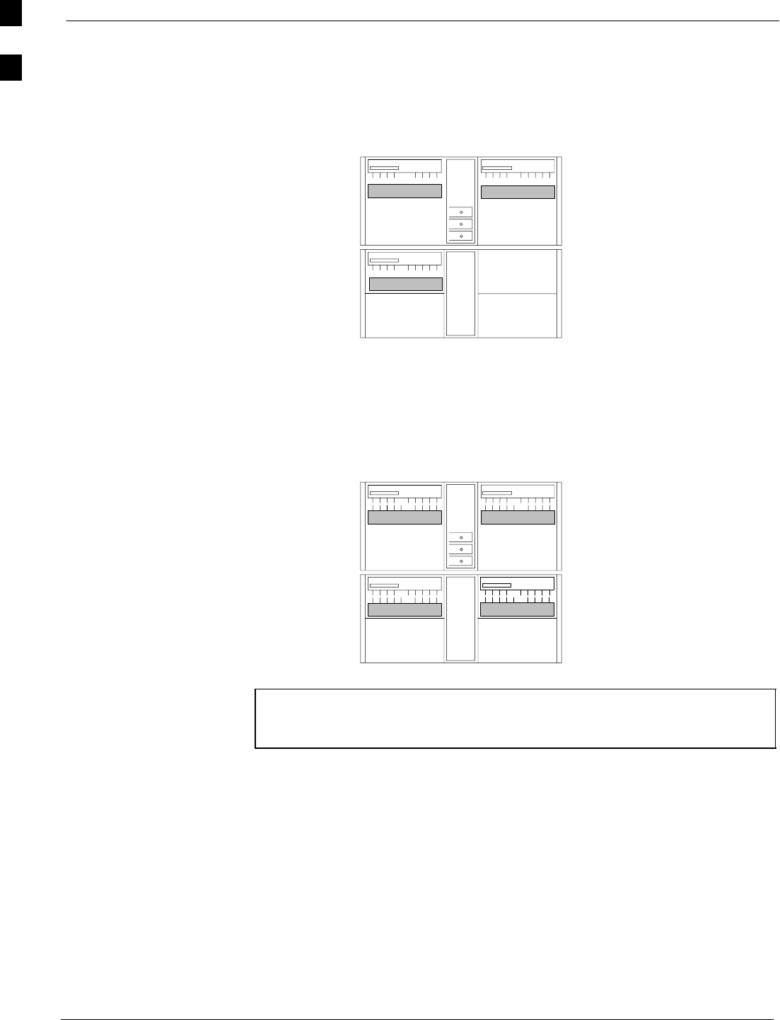
Carrier Add Instructions 68P64115A19–4
Mar 2003
1X SC 4812T-MC BTS Hardware Installation - Software Release R2.16.1.x
CONTROLLED INTRODUCTION
A-4
Figure A-1: PLC Filler Plate Location (3X3 Enhanced Trunking Module)
1C
1A 1B
C1
C2
C1
C2
C1
C2
MCM
1
SC4812T–MC
Carrier
Numbering
Carrier
Numbering
3 Sector 3X3 ETM
3 Sector
3 Sector
S1
S2
S3
CLPACLPA
CLPA
Figure A-2: PLC Filler Plate Location (4X4 Enhanced Trunking Module)
1C
1A 1B
C1 C1
C1
MCM
1
SC4812T–MC
Carrier
Numbering
Carrier
Numbering
3 Sector 4X4 ETM
3 Sector
3 Sector
S1
S2
S3
CLPACLPA
CLPA 1C
CLPA
NOTE Figure A-1 and Figure A-2 show single carrier with CLPA
locations plus PLC Filler Plates (shown in gray) to be removed
when another carrier is added.
A
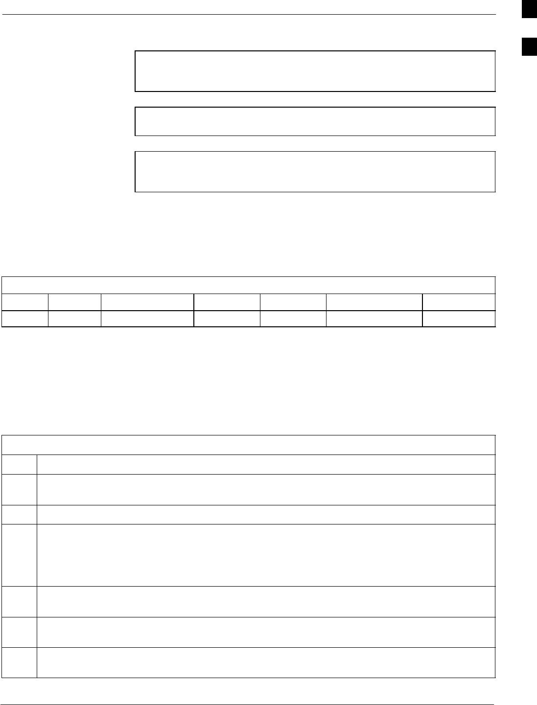
Carrier Add Instructions
68P64115A19–4
Mar 2003 1X SC 4812T-MC BTS Hardware Installation - Software Release R2.16.1.x
CONTROLLED INTRODUCTION
A-5
Carrier Add (6 Sector)
NOTE After completing the installation steps for carrier add, calibrate,
optimize, and ATP the new carrier. Enable the new carrier at a
low power level
CAUTION If the ATP is not possible during peak air time, download a
default BLO (40 dB) and enable BBX carrier
NOTE All PAs for the carrier under test must be INS during testing. For
carriers not under test, key one BBX per carrier to a minimum
power level.
Carrier Add Matrix (6 Sector)
Table A-4 identifies the number of components needed when adding a
carrier. This matrix is for 6 Sector only.
Table A-4: Six Sector Carrier Add Matrix
Add Fan Add BBX Add PA Add MCC Add PLC Filler Removal CCCP PS Add
Carrier 2 None BBX 7 thru BBX 12 6 or 8 As Needed 6 or 8 1**
** Add C–CCP Power Supply #3 Card for a 2nd Carrier.
Installing a Second Carrier
Follow the step–by–step procedure (Table A-5) to add a second carrier to
a 6 sector SC 4812T–MC BTS frame.
Table A-5: Installing a Second Carrier
Step Action
1Remove the PA Fan Trays from PA Cages (see FRU Guide for removal instructions– SC 4812T–MC
FRU Guide 68P64115A20).
2Remove the PLC Filler panels from the PA Cage using a T15 Torx driver
3Follow the instructions in the FRU Guide for installing CLPA modules and PA Fan Trays in the
Carrier 2 locations indicated in Figure 22–2.
NOTE
PA Fan Trays are installed over CLPAs. PA Fan trays are not required in locations without CLPAs.
4Add a 3rd C–CCP Power Suppy Card to the frame. Refer toinstall instructions (see FRU Guide – SC
4812T–MC 68P64115A20
5Install BBXs and MCCs (see Table A-4, Figure A-3 and Figure A-4) for required number
corresponding to carrier of newly installed CLPAs.
6All PAs for the carrier under test must be INS during testing. For carriers not under test, key one BBX
per carrier to a minimum power level.
A
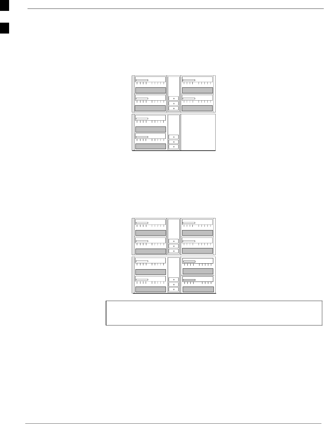
Carrier Add Instructions 68P64115A19–4
Mar 2003
1X SC 4812T-MC BTS Hardware Installation - Software Release R2.16.1.x
CONTROLLED INTRODUCTION
A-6
Figure A-3: PLC Filler Plate Locations 6 Sector (3X3 Enhanced Trunking Module)
1C
3C
3A
1A 1B
3B
C1
C1
C1
C1
S4
MCM
1
SC4812T–MC
Carrier
Numbering Carrier
Numbering
6 Sector 3X 3 ETM
6 Sector
S5
S6
S1
S2
S3
MCM
2
CLPACLPA
CLPACLPA
CLPA
CLPA
6 Sector
C1
C1
Figure A-4: PLC Filler Plate Locations (4X4 Enhanced Trunking Module)
1C
3C
3A
1A 1B
3B
C1
C1
C1
C1
S4
MCM
1
SC4812T–MC
Carrier
Numbering Carrier
Numbering
6 Sector 4 X 4 ETM
6 Sector
S5
S6
S1
S2
S3
MCM
2
CLPACLPA
CLPACLPA
CLPA
CLPA
6 Sector
C1
C1
1D
3D
CLPA
CLPA
C1
C1
NOTE Figure A-3 and Figure A-4 show single carrier with CLPA
locations plus PLC Filler Plates (shown in gray) to be removed
when another carrier is added.
A

CONTROLLED INTRODUCTION
Mar 2003 1X SC 4812T-MC BTS Hardware Installation - Software Release R2.16.1.x Index-1
Index

Index 68P64115A19–4
1X SC 4812T-MC BTS Hardware Installation - Software Release R2.16.1.x
CONTROLLED INTRODUCTION
Mar 2003
Index-2
Numbers
120 Degree Sector Receive Path Cabling, 2-31, 2-37,
4-10, 4-15
120 Degree Sector Transmit Path Cabling, 2-28, 2-29,
2-33, 2-34, 4-8, 4-12
3–Sector Duplexed Cabling, 4-20
3–Sector Duplexed Cabling Configurations, 4-20
3–Sector Duplexed Directional Coupler to RFDS
Cabling Table, 4-21
3–Sector Non–Duplexed Cabling, 4-17
3–Sector Non–Duplexed Directional Coupler to
RFDS Cabling Table, 4-19
3-Sector Non-Duplexed Cabling Configuration, 4-18
6–Sector Duplexed Cabling, 4-22
6–Sector Duplexer–to–BTS Cabling Table, 4-24
60 degree sector configuration, 2-30, 4-9
60 Degree Sector Receive Path Cabling, 2-31, 4-10
6-Sector Dup, 4-23
A
acronyms, 1-3
Alarm / Span Cabling, 2-10
Alarm cable installation, 2-12
Alarm Connectors Pin and Signal Information, 2-15
Alarm signal specifications, 2-13
AMR, 1-3
Antenna Sharing, 3-8
ATP, 1-3
B
BBX, 1-3
BLO, 1-3
BTS, 1-3
BTS 120 Degree Sector (3 Sector) Receive Path
Cabling, 2-36, 4-14
BTS 120 Degree Sector (3 Sector) Transmit Path
Cabling, 2-33, 4-12
BTS 60 Degree Sector (6 Sector) Transmit Path
Cabling, 2-28, 4-8
BTS earth ground cables, 2-39
BTS Frame Site Layout, 1-7
BTS MC Expansion Frame (+27 V Configuration),
3-3
BTS Power Cabling, 2-41, 2-48
BTS Power Cabling for + 27 V Power Cables, 2-48
C
C–CCP, 1-3
Cable descriptions and part numbers, 2-7
Cable labels, 2-10
Cable Run List, 2-21
Cable run list, 2-11
Cabling diagram, 2-11
Cabling installation order, 2-2
Carrier Add Instructions, A-2
CBSC, 1-3
CCD, 1-3
CDMA, 1-3
CDMA RFDS Function, 4-4, 4-6
CE, 1-3
checklist, 5-2
Clean up the site, 5-2
CLI, 1-3
CLPA, 1-3
CM, 1-3
CMR, 1-3
Configurations Supported, 2-2
CSM, 1-3
Customer Equipment Considerations and System
Constrains, 3-10
D
DBM, 1-3
DBPF, 1-3
DDC, 1-3
Dimensions and Clearances for the BTS, 1-7
Directional Couplers and Bracket , 4-2
DSP, 1-3
Duplex Directional Couplers (DDC) and Mounting
Bracket, 4-3
E
Earth Ground Cabling, 2-39

Index
68P64115A19–4
CONTROLLED INTRODUCTION
Mar 2003 1X SC 4812T-MC BTS Hardware Installation - Software Release R2.16.1.x Index-3
EMPC, 1-3
Environment, 5-3
Equipment Compliance, 2-18
ETM, 1-3
Expansion Cable/Hardware Descriptions, 3-2
Expansion Frame (+27 V BTS Configuration), 3-2
Expansion Frame cabling diagram, 3-6
Expansion Frame I/O Plate, 2-5
Expansion Frame Inter–Frame Cabling, 3-7
Expansion I/O plate, 3-3
External Components, 1-10
F
Foreword, xiii
Frame Identification, 1-8
FRU, 1-3
FSI, 1-3
G
General Safety, xv
GLI, 1-3
Global Positioning System (GPS), 3-10
GPS, 1-3
H
HSO, 1-3
HSO expansion procedure, 3-13
I
I&Q, 1-3
I/O Plate, 1-9
In–Frame Components, 1-10
Install earth grounding cables, 2-40
Installation Completion Checklist, 5-4
Installation completion checklist, 5-4
Installing Power Cables, 2-47
Installing RF Cables, 4-19, 4-21, 4-24
Inter–frame cables, 3-2
L
LAPD, 1-3
LFR, 1-3
LFR cable cable L pin/signal information, 2-25
Lighting fixtures, 5-3
LMF, 1-3
Local Area Network (LAN) Expansion Installation,
3-14
LORAN, 1-3
Low Frequency Receiver / High Stability Oscillator
(LFR/HSO) Cabling, 2-24
LPA, 1-3
M
Manual Overview, Abbreviations and Acronyms, 1-2
Manual Structure, 1-2
Materials, 5-3
MC, 1-3
MC CLPA Cage, 1-10
MCC, 1-3
MCIO, 1-3
MCM, 1-4
MGLI, 1-4
MM, 1-4
MMI, 1-4
MPC, 1-4
MSC, 1-4
O
OMCR, 1-4
Omni/Omni systems, 2-9
Optimize the system, 5-2
Optional BTS Equipment Identification, 4-2
Overall Cabling Diagram (Single Frame), 2-9
P
PAC, 1-4
PCS, 1-4
Pin/Signal Information for ARM A Cable, 2-16, 2-17
PLC, 1-4
PN, 1-4

Index 68P64115A19–4
1X SC 4812T-MC BTS Hardware Installation - Software Release R2.16.1.x
CONTROLLED INTRODUCTION
Mar 2003
Index-4
Power Alarms Card (PAC), 2-13
Power distribution cabling diagram for systems with
one power feed, 2-44
Power distribution cabling diagram for systems with
two power feeds, 2-45
Power Distribution Cage MC Configuration, 1-10
Power Distribution shelf PDS, 1-9
Pre–connection checklist, 2-47
PSM, 1-4
PSTN, 1-4
PWM, 1-4
Q
QPSK, 1-4
R
Remote GPS (RGD) expansion procedure, 3-12
Remote GPS Distribution (RGD) Board, 3-7
Remote GPS Distribution (RGD) Card, 2-6
Remove debris, 5-3
Required Documentation, 1-5
Revision History, xvii
RF GPS Cabling Diagram, 2-20
RF GPS Cabling Installation Procedure, 2-21
RF Interfaces, 4-4
RF RGPS Expansion Installation Considerations,
3-10
RFDS, 1-4
RFDS , 4-4
RGD, 1-4
RGD Board Cable connections, 3-7
RGPS Cabling Diagrams, 2-22
RSSI, 1-4
RX Antenna Configuration, 2-26
S
SC4812T–MC Expansion Frame I/O Plate, 2-4
SCAP, 1-4
Setting Frame C–CCP Shelf Configuration Switch,
3-16
Site Document , 1-5
Site I/O, 1-9
Site I/O and Span I/O Boards, 2-6
Span I/O, 1-9
Span I/O board (A) installation, 2-12
Span I/O board (B) installation, 2-12
Span line cable pin numbering, 2-14
Specifications, 1-6
System to Feed Multiple BTSs from One GPS
Antenna, 3-11
T
TCH, 1-4
Timing Sources, 2-19
Tools, 5-3
Tools and equipment required, 2-46
Top Interconnect Plate, 2-3
TSI, 1-4
TX antenna; –48 V configuration, 2-27
W
What’s Next, 5-2